EP2604898B1 - Device for mounting and removing valve packing and method thereof - Google Patents
Device for mounting and removing valve packing and method thereof Download PDFInfo
- Publication number
- EP2604898B1 EP2604898B1 EP10855946.9A EP10855946A EP2604898B1 EP 2604898 B1 EP2604898 B1 EP 2604898B1 EP 10855946 A EP10855946 A EP 10855946A EP 2604898 B1 EP2604898 B1 EP 2604898B1
- Authority
- EP
- European Patent Office
- Prior art keywords
- packing
- mounting
- valve
- gland bushing
- flange
- Prior art date
- Legal status (The legal status is an assumption and is not a legal conclusion. Google has not performed a legal analysis and makes no representation as to the accuracy of the status listed.)
- Active
Links
Images

Classifications
-
- B—PERFORMING OPERATIONS; TRANSPORTING
- B25—HAND TOOLS; PORTABLE POWER-DRIVEN TOOLS; MANIPULATORS
- B25B—TOOLS OR BENCH DEVICES NOT OTHERWISE PROVIDED FOR, FOR FASTENING, CONNECTING, DISENGAGING, OR HOLDING
- B25B27/00—Hand tools, specially adapted for fitting together or separating parts or objects whether or not involving some deformation, not otherwise provided for
- B25B27/0028—Tools for removing or installing seals
-
- F—MECHANICAL ENGINEERING; LIGHTING; HEATING; WEAPONS; BLASTING
- F16—ENGINEERING ELEMENTS AND UNITS; GENERAL MEASURES FOR PRODUCING AND MAINTAINING EFFECTIVE FUNCTIONING OF MACHINES OR INSTALLATIONS; THERMAL INSULATION IN GENERAL
- F16K—VALVES; TAPS; COCKS; ACTUATING-FLOATS; DEVICES FOR VENTING OR AERATING
- F16K43/00—Auxiliary closure means in valves, which in case of repair, e.g. rewashering, of the valve, can take over the function of the normal closure means; Devices for temporary replacement of parts of valves for the same purpose
-
- F—MECHANICAL ENGINEERING; LIGHTING; HEATING; WEAPONS; BLASTING
- F16—ENGINEERING ELEMENTS AND UNITS; GENERAL MEASURES FOR PRODUCING AND MAINTAINING EFFECTIVE FUNCTIONING OF MACHINES OR INSTALLATIONS; THERMAL INSULATION IN GENERAL
- F16J—PISTONS; CYLINDERS; SEALINGS
- F16J15/00—Sealings
- F16J15/16—Sealings between relatively-moving surfaces
- F16J15/18—Sealings between relatively-moving surfaces with stuffing-boxes for elastic or plastic packings
- F16J15/184—Tightening mechanisms
-
- F—MECHANICAL ENGINEERING; LIGHTING; HEATING; WEAPONS; BLASTING
- F16—ENGINEERING ELEMENTS AND UNITS; GENERAL MEASURES FOR PRODUCING AND MAINTAINING EFFECTIVE FUNCTIONING OF MACHINES OR INSTALLATIONS; THERMAL INSULATION IN GENERAL
- F16J—PISTONS; CYLINDERS; SEALINGS
- F16J15/00—Sealings
- F16J15/16—Sealings between relatively-moving surfaces
- F16J15/18—Sealings between relatively-moving surfaces with stuffing-boxes for elastic or plastic packings
- F16J15/189—Means for facilitating the removal of the packing
-
- F—MECHANICAL ENGINEERING; LIGHTING; HEATING; WEAPONS; BLASTING
- F16—ENGINEERING ELEMENTS AND UNITS; GENERAL MEASURES FOR PRODUCING AND MAINTAINING EFFECTIVE FUNCTIONING OF MACHINES OR INSTALLATIONS; THERMAL INSULATION IN GENERAL
- F16K—VALVES; TAPS; COCKS; ACTUATING-FLOATS; DEVICES FOR VENTING OR AERATING
- F16K41/00—Spindle sealings
- F16K41/02—Spindle sealings with stuffing-box ; Sealing rings
-
- Y—GENERAL TAGGING OF NEW TECHNOLOGICAL DEVELOPMENTS; GENERAL TAGGING OF CROSS-SECTIONAL TECHNOLOGIES SPANNING OVER SEVERAL SECTIONS OF THE IPC; TECHNICAL SUBJECTS COVERED BY FORMER USPC CROSS-REFERENCE ART COLLECTIONS [XRACs] AND DIGESTS
- Y10—TECHNICAL SUBJECTS COVERED BY FORMER USPC
- Y10T—TECHNICAL SUBJECTS COVERED BY FORMER US CLASSIFICATION
- Y10T137/00—Fluid handling
- Y10T137/0318—Processes
- Y10T137/0402—Cleaning, repairing, or assembling
- Y10T137/0441—Repairing, securing, replacing, or servicing pipe joint, valve, or tank
- Y10T137/0486—Specific valve or valve element mounting or repairing
-
- Y—GENERAL TAGGING OF NEW TECHNOLOGICAL DEVELOPMENTS; GENERAL TAGGING OF CROSS-SECTIONAL TECHNOLOGIES SPANNING OVER SEVERAL SECTIONS OF THE IPC; TECHNICAL SUBJECTS COVERED BY FORMER USPC CROSS-REFERENCE ART COLLECTIONS [XRACs] AND DIGESTS
- Y10—TECHNICAL SUBJECTS COVERED BY FORMER USPC
- Y10T—TECHNICAL SUBJECTS COVERED BY FORMER US CLASSIFICATION
- Y10T137/00—Fluid handling
- Y10T137/598—With repair, tapping, assembly, or disassembly means
- Y10T137/6065—Assembling or disassembling reciprocating valve
- Y10T137/6069—Having particularly packed or sealed mechanical movement actuator
Definitions
- the present invention relates to a valve comprising a device and method for mounting and removing a valve packing, and more particularly, to a device and method for mounting and removing a valve packing by which a packing can be mounted and removed without disassembling a driving section and a valve disc.
- a lower portion of the stem is submerged in a fluid such as a high pressure vapor, water, oil, or the like, an upper portion of the stem is connected to a handle configured to move the stem, or the like, and a packing is provided to prevent leakage of the fluid from the lower portion of the stem through an outer circumferential surface of the stem.
- the packing which is a consumable part configured to seal the valve, loses its sealing performance due to repeated vertical movement of the stem.
- a decrease in sealing performance means that, in particular, radioactive contamination may occur from a nuclear power plant, and accordingly, a device for effectively exchanging a packing having a decreased sealing performance in a state of preventing such contamination is needed.
- the stem, the packing flange and the gland bushing are moved upward, and a high pressure of water or air is injected using a special tool for packing removal (a hydro pic) to raise the packing, removing the packing.
- a special tool for packing removal a hydro pic
- the lantern ring can also be removed in the same manner as the packing.
- a flow path inlet should be rewelded or a cover should be tightly fastened to prevent the leakage. Due to the leakage risk, in the case of some valves used in the nuclear power plant or the chemical plant, after a valve disc is moved upwardly to be closely attached to a valve body to prevent leakage without using the special tool for packing removal, the stud bolt and the stud nut are removed, the stem, the packing flange and the gland bushing are moved upwardly to obtain a working space, and then the packing and the lantern ring are extracted using a packing removal tool (not shown).
- a valve comprising a device for mounting and removing a packing installed at the valve stem to prevent leakage of a fluid from said valve including a plurality of rods, a ring-shaped support connected to the rods, threads formed at outer circumferential surfaces of upper portions of the rods; and nuts fastened onto the threads, wherein a plurality of packings or a single packing are/is passed and stacked by the rods, a gland bushing is passed by the rods to be disposed on the packing(s), the support supports the packing(s), and the nuts are fastened to the threads to closely attach the packing(s) to the gland bushing.
- US 5,709,514 A refers to a method of mounting a valve packing installed to prevent leakage of a fluid, wherein a guide ring, a beveled washer, a stud nut and a stud bolt are assembled on a gland bushing.
- valve comprising a packing mounting and removing device according to claim 1 and providing methods according to claims 5 and 6, respectively.
- the device and method of the present invention since a special device for removing a packing is not needed and the packing can be mounted and removed without disassembling a driving section and a valve disc section, time and cost consumed to mount and remove the packing can be notably reduced.
- FIG. 1 is a cross-sectional view showing an exemplary embodiment of a valve at which a packing mounting and removing device according to the present invention is installed.
- the packing mounting and removing device of the present invention includes a packing mounting and removing rod 350 configured to easily mount and remove a packing ring, a rod support 340 configured to support the packing mounting and removing rod and function as a packing follower, a rod fixing nut 360 mounting and removing a packing, a hermetical seal 361 formed of a rubber material and disposed under a nut, a thread 370 disposed on the rod and configured to fasten a fixing nut, a packing flange 300 having an accommodating groove 310 configured to accommodate an upper portion of the packing mounting and removing rod, a gland bushing 320 having a through-hole configured to obtain a space through which the packing mounting and removing rod 350 passes and fix the rod, and a packing 380 and a lantern ring 390 having through-holes configured to enable passage of the packing mounting and
- FIGS. 2 , 3 and 4 show a structure of the packing mounting and removing device of the present invention including the packing mounting and removing rod 350, the rod support 340, the rod fixing nut 360, and the thread 370 on the rod, characterized in that two or more packing mounting and removing rods 350 may be provided and the thread 370 capable of fastening the fixing nut 360 to an upper portion of the rod 350 may be provided.
- the packing mounting and removing device may have various shapes such as a circular shape as shown in FIG. 2 or a polygonal shape as shown in FIG. 3 , and the rod support 340 and the rod 350 may be an integrated type or a separated type. As shown in FIG.
- the rod support 340 may have an integrated structure or a structure divided into two or more.
- the packing can be freely mounted and removed without removing a driving section connected to an upper end of a stem 10.
- the packing flange 300 includes the accommodating groove 310 formed at a lower end of a flange to accommodate the packing mounting and removing rod 350, and the gland bushing 320 has a structure with a through-hole formed from a lower end to an upper end thereof to accommodate the packing mounting and removing rod 350.
- a method of mounting the packing 380 using the packing mounting and removing device shown in FIGS. 2 , 3 and 4 without disassembling the driving section includes removing a stud bolt 17, a stud nut 13, a guide bushing 14, a beveled washer 15 and a guide ring 16, moving the packing flange 300 and the gland bushing 320 upwardly, mounting the packing mounting and removing device including the packing mounting and removing rod 350, the rod support 340, a rod fixing bolt 360 and the thread 370 on the rod, mounting the entire packing 380 from the lowermost packing ring to the uppermost packing ring by passing the packing mounting and removing rod 350 therethrough, mounting the gland bushing 320 by passing the removing rod 350 therethrough, inserting the hermetical seal 361 formed of a rubber material between the packing mounting and removing rod 350 and the rod fixing nut 360, fastening the rod fixing nut 360, positioning the packing flange 300 on the gland bushing 320, and assembling the guide ring 16, the beveled washer 15, the stud nut 17 and the
- the method of removing the valve packing 380 may include a lifting unit 500 disposed between the gland bushing 320 and a bonnet 12 to raise the gland bushing 320.
Landscapes
- Engineering & Computer Science (AREA)
- General Engineering & Computer Science (AREA)
- Mechanical Engineering (AREA)
- Details Of Valves (AREA)
- Sealing Devices (AREA)
Description
- The present invention relates to a valve comprising a device and method for mounting and removing a valve packing, and more particularly, to a device and method for mounting and removing a valve packing by which a packing can be mounted and removed without disassembling a driving section and a valve disc.
- In general, in a valve configured to perform a disc opening/closing function through vertical movement of a stem, a lower portion of the stem is submerged in a fluid such as a high pressure vapor, water, oil, or the like, an upper portion of the stem is connected to a handle configured to move the stem, or the like, and a packing is provided to prevent leakage of the fluid from the lower portion of the stem through an outer circumferential surface of the stem. The packing, which is a consumable part configured to seal the valve, loses its sealing performance due to repeated vertical movement of the stem. A decrease in sealing performance means that, in particular, radioactive contamination may occur from a nuclear power plant, and accordingly, a device for effectively exchanging a packing having a decreased sealing performance in a state of preventing such contamination is needed.
- Two methods of removing a packing from a valve of the related art are known. A first method of exchanging the packing in a state in which all of a stud bolt, a stud nut, a guide bushing, a beveled washer, a guide ring, a packing flange and a gland bushing are removed, and a second method of exchanging the packing in a state in which the stud bolt and the stud nut are removed and a stem is moved upward to closely attach a disc to a bonnet are provided. Since a fluid in a pipe should not be leaked during exchange of the packing in a nuclear power plant, an oil refining plant, or a chemical plant, the second method is used. In this method, after removing the stud bolt and the stud nut, the stem, the packing flange and the gland bushing are moved upward, and a high pressure of water or air is injected using a special tool for packing removal (a hydro pic) to raise the packing, removing the packing. Selectively, in a valve including a lantern ring and a leakage collecting flow path to collect leakage, the lantern ring can also be removed in the same manner as the packing.
- When the packing is removed by the second method, in order to prevent leakage through a special tool mounting flow path, a flow path inlet should be rewelded or a cover should be tightly fastened to prevent the leakage. Due to the leakage risk, in the case of some valves used in the nuclear power plant or the chemical plant, after a valve disc is moved upwardly to be closely attached to a valve body to prevent leakage without using the special tool for packing removal, the stud bolt and the stud nut are removed, the stem, the packing flange and the gland bushing are moved upwardly to obtain a working space, and then the packing and the lantern ring are extracted using a packing removal tool (not shown). In this case, since the working space that can be obtained by moving the packing flange and the gland bushing upwardly is very narrow and limited, the work becomes difficult, and tangling is generated within the packing to cause limitation in removal of the packing such as damage to the packing. In addition, since the packing removal tool formed of a metal material scratches the stem during removal of the packing, slight leakage may be generated through the scratches even when a new packing is mounted.
- Documents
JP S57-167565 A DE 167 084 disclose a valve comprising a device for mounting and removing a packing installed at the valve stem to prevent leakage of a fluid from said valve including a plurality of rods, a ring-shaped support connected to the rods, threads formed at outer circumferential surfaces of upper portions of the rods; and nuts fastened onto the threads, wherein a plurality of packings or a single packing are/is passed and stacked by the rods, a gland bushing is passed by the rods to be disposed on the packing(s), the support supports the packing(s), and the nuts are fastened to the threads to closely attach the packing(s) to the gland bushing. -
US 5,709,514 A refers to a method of mounting a valve packing installed to prevent leakage of a fluid, wherein a guide ring, a beveled washer, a stud nut and a stud bolt are assembled on a gland bushing. - In order to solve the foregoing and/or other problems, it is an aspect of the present invention to provide a device and method for removing and mounting a packing more simply without generation of contamination upon wear of the packing.
- The foregoing and/or other aspects of the present invention may be achieved by providing a valve comprising a packing mounting and removing device according to claim 1 and providing methods according to claims 5 and 6, respectively.
- According to the device and method of the present invention, since a special device for removing a packing is not needed and the packing can be mounted and removed without disassembling a driving section and a valve disc section, time and cost consumed to mount and remove the packing can be notably reduced.
-
-
FIG. 1 is a cross-sectional view of a valve at which a packing mounting and removing device according to the present invention is installed; -
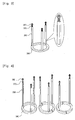
FIG. 2 is a perspective view of the packing mounting and removing device according to the present invention; -
FIG. 3 and 4 show perspective views of various embodiments of the packing mounting and removing device according to the present invention; and -
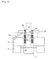
FIG. 5 is a cross-sectional view of the valve at which the packing mounting and removing device according to the present invention is to be removed. - Reference will now be made in detail to the embodiments of the present invention, examples of which are illustrated in the accompanying drawings.
-
FIG. 1 is a cross-sectional view showing an exemplary embodiment of a valve at which a packing mounting and removing device according to the present invention is installed. As shown inFIG. 1 , the packing mounting and removing device of the present invention includes a packing mounting and removingrod 350 configured to easily mount and remove a packing ring, arod support 340 configured to support the packing mounting and removing rod and function as a packing follower, arod fixing nut 360 mounting and removing a packing, ahermetical seal 361 formed of a rubber material and disposed under a nut, athread 370 disposed on the rod and configured to fasten a fixing nut, apacking flange 300 having anaccommodating groove 310 configured to accommodate an upper portion of the packing mounting and removing rod, a gland bushing 320 having a through-hole configured to obtain a space through which the packing mounting and removingrod 350 passes and fix the rod, and apacking 380 and alantern ring 390 having through-holes configured to enable passage of the packing mounting and removing rod. Selectively, therod 350 may have a circular or polygonal cross-sectional shape. -
FIGS. 2 ,3 and 4 show a structure of the packing mounting and removing device of the present invention including the packing mounting and removingrod 350, therod support 340, therod fixing nut 360, and thethread 370 on the rod, characterized in that two or more packing mounting and removingrods 350 may be provided and thethread 370 capable of fastening thefixing nut 360 to an upper portion of therod 350 may be provided. Preferably, the packing mounting and removing device may have various shapes such as a circular shape as shown inFIG. 2 or a polygonal shape as shown inFIG. 3 , and therod support 340 and therod 350 may be an integrated type or a separated type. As shown inFIG. 4 , therod support 340 may have an integrated structure or a structure divided into two or more. Preferably, as thesupport 340 is divided into two or more, the packing can be freely mounted and removed without removing a driving section connected to an upper end of astem 10. - As shown in
FIG. 1 , thepacking flange 300 includes theaccommodating groove 310 formed at a lower end of a flange to accommodate the packing mounting and removingrod 350, and the gland bushing 320 has a structure with a through-hole formed from a lower end to an upper end thereof to accommodate the packing mounting and removingrod 350. - A method of mounting the
packing 380 using the packing mounting and removing device shown inFIGS. 2 ,3 and 4 without disassembling the driving section includes removing astud bolt 17, astud nut 13, a guide bushing 14, abeveled washer 15 and aguide ring 16, moving thepacking flange 300 and the gland bushing 320 upwardly, mounting the packing mounting and removing device including the packing mounting and removingrod 350, the rod support 340, arod fixing bolt 360 and thethread 370 on the rod, mounting theentire packing 380 from the lowermost packing ring to the uppermost packing ring by passing the packing mounting and removingrod 350 therethrough, mounting the gland bushing 320 by passing the removingrod 350 therethrough, inserting thehermetical seal 361 formed of a rubber material between the packing mounting and removingrod 350 and therod fixing nut 360, fastening therod fixing nut 360, positioning thepacking flange 300 on the gland bushing 320, and assembling theguide ring 16, thebeveled washer 15, thestud nut 17 and thestud bolt 13. - The method of removing the
valve packing 380 may include alifting unit 500 disposed between the gland bushing 320 and abonnet 12 to raise the gland bushing 320.
Claims (7)
- A valve comprising a stem (10) with a valve disc (11) being guided in a bonnet (12), a packing flange (300) and a device for mounting and removing a packing installed at said stem to prevent leakage of a fluid from said valve, the packing mounting and removing device comprising:a plurality of rods (350) having long shapes;a ring-shaped support (340) connected to the rods (350);threads (370) formed at outer circumferential surfaces of upper portions of the rods (350); andnuts (360) fastened onto the threads (370),wherein a plurality of packings (380) are passed and stacked by the rods (350), a gland bushing (320) is passed by the rods (350) to be disposed on the packings (380), the support (340) supports the packings (380), and the nuts (360) are fastened to the threads (370) to closely attach the packings (380) to the gland bushing (320), wherein said packing flange (300) is positioned on said gland bushing (320) and, whereinsaid gland bushing (320) is fixed both to said packing flange (300) and to said bonnet (12) of the valve by means of stud bolts (17) passing through the said packing flange (300) and said gland bushing (320), and by means of stud nuts (13), guide rings (16) and beveled washers (15) on the side of said packing flange (300) facing away from both said gland bushing (320) and said bonnet (12).
- The valve according to claim 1, in which said packing flange (300) comprises an accommodating groove (310) configured to accommodate the nuts (360) on the gland bushing (320).
- The valve according to claim 1, wherein the support (340) of the device for mounting and removing the packing is divided into a plurality of parts.
- The valve packing mounting and removing device according to claim 1, in which the rods (350) of the device for mounting and removing the packing have circular or polygonal cross-sectional shapes.
- A method of mounting a valve packing installed to prevent leakage of a fluid, the method comprising:fitting a packing (380) onto a rod (350);fitting a gland bushing (320) onto the rod (350);fastening a rod fixing nut (360);disposing a packing flange (300) on the gland bushing (320); andassembling a guide ring (16) and a beveled washer (15) onto said packing flange (300) by means of a stud nut (13) to be fixed on a stud bolt (17), the stud bolt (17) thereby passing through the said packing flange (300) and said gland bushing (320).
- A method of removing a valve packing installed to prevent leakage of a fluid, the method comprising:removing a stud bolt (17), a stud nut (13), a beveled washer (15) and a guide ring (16), the stud bolt (17) passing through a packing flange (300) and a gland bushing (320);moving said packing flange (300) upwardly;moving a packing mounting and removing device coupled to a packing (380) and said gland bushing (320) upwardly;removing a nut (360); anddemounting a packing fitted onto a rod (350).
- The method of removing the valve packing according to claim 6, wherein a lifting unit (500) is disposed between the gland bushing (320) and a bonnet (12) to raise the gland bushing (320).
Applications Claiming Priority (2)
| Application Number | Priority Date | Filing Date | Title |
|---|---|---|---|
| KR1020100076272A KR101171571B1 (en) | 2010-08-09 | 2010-08-09 | Device and method for installation and removal of valve packing |
| PCT/KR2010/005908 WO2012020879A1 (en) | 2010-08-09 | 2010-09-01 | Device for mounting and removing valve packing and method thereof |
Publications (3)
| Publication Number | Publication Date |
|---|---|
| EP2604898A1 EP2604898A1 (en) | 2013-06-19 |
| EP2604898A4 EP2604898A4 (en) | 2014-02-05 |
| EP2604898B1 true EP2604898B1 (en) | 2016-11-09 |
Family
ID=45567822
Family Applications (1)
| Application Number | Title | Priority Date | Filing Date |
|---|---|---|---|
| EP10855946.9A Active EP2604898B1 (en) | 2010-08-09 | 2010-09-01 | Device for mounting and removing valve packing and method thereof |
Country Status (6)
| Country | Link |
|---|---|
| US (1) | US8863768B2 (en) |
| EP (1) | EP2604898B1 (en) |
| JP (1) | JP5678186B2 (en) |
| KR (1) | KR101171571B1 (en) |
| CN (1) | CN103069201B (en) |
| WO (1) | WO2012020879A1 (en) |
Families Citing this family (21)
| Publication number | Priority date | Publication date | Assignee | Title |
|---|---|---|---|---|
| DE102008030174A1 (en) * | 2008-06-27 | 2009-12-31 | PROMESS Gesellschaft für Montage- und Prüfsysteme mbH | Sealing ring and device and method for mounting a sealing ring |
| KR101388262B1 (en) * | 2012-10-29 | 2014-04-25 | 현대제철 주식회사 | Supporting appratus for packing replacement of oxygen compressor |
| US9863552B2 (en) | 2014-06-24 | 2018-01-09 | Jdv Control Valves Co., Ltd. | Fluid valve and a single shaft-sealing module thereof |
| CN104308800A (en) * | 2014-10-21 | 2015-01-28 | 苏州道森钻采设备股份有限公司 | Rod pressing tooling for assembling valves |
| KR200481626Y1 (en) * | 2015-01-02 | 2016-10-21 | 한전케이피에스 주식회사 | Apparatus for removing gasket |
| US9969069B2 (en) | 2015-04-27 | 2018-05-15 | United Technologies Corporation | Methods and tools for pressing a ring seal into a component |
| RU2689869C1 (en) * | 2015-11-10 | 2019-05-29 | Л'Эр Ликид, Сосьете Аноним Пур Л'Этюд Э Л'Эксплуатасьон Де Проседе Жорж Клод | Valve adaptation for valve with upper connector in cryogenic equipment |
| KR102363000B1 (en) * | 2015-11-10 | 2022-02-16 | 레르 리키드 쏘시에떼 아노님 뿌르 레드 에렉스뿔라따시옹 데 프로세데 조르즈 클로드 | Adaptation of press-fit valves for top-inserted valves in cryogenic service |
| CN109210270B (en) * | 2017-07-01 | 2020-04-21 | 上海威纳工程技术有限公司 | Pressure precise control type packing installation method |
| CN109175944A (en) * | 2018-10-12 | 2019-01-11 | 江苏核电有限公司 | A kind of self-sealing check-valves self-sealing packing mounting device and its operating method |
| KR102144584B1 (en) * | 2019-10-16 | 2020-08-13 | 주식회사 신한정공 | Replacement method of seal ring at hydraulic turbine |
| US11143314B1 (en) * | 2020-03-25 | 2021-10-12 | Fisher Controls International Llc | Methods and apparatus to load a valve packing |
| CN114952713B (en) * | 2021-02-26 | 2024-06-25 | 中国石油天然气股份有限公司 | Sealing packing disassembly and assembly device and oil transfer crankshaft pump |
| CN113884255B (en) * | 2021-09-29 | 2024-10-25 | 宁波东鼎阀门有限公司 | Valve packing installation and detecting system |
| JP7651176B2 (en) * | 2021-10-21 | 2025-03-26 | 株式会社Wadeco | Gland packing replacement device and replacement method |
| US12359747B2 (en) * | 2022-08-26 | 2025-07-15 | Fisher Controls International Llc | Valve packing apparatus and related methods |
| US12215801B2 (en) | 2022-08-26 | 2025-02-04 | Fisher Controls International Llc | Valve packing apparatus and related methods |
| KR102770865B1 (en) * | 2023-05-18 | 2025-02-24 | 한화토탈에너지스 주식회사 | Tool for removing gland packing |
| CN116810708B (en) * | 2023-06-01 | 2026-02-17 | 中核检修有限公司 | Extraction device and installation and use method thereof |
| KR102704914B1 (en) * | 2024-04-18 | 2024-09-11 | (주)지브이케이 | Globe Valve |
| KR102884677B1 (en) | 2025-04-15 | 2025-11-13 | (주)정도기계 | Replacement type stem packing module for butterfly valve |
Family Cites Families (31)
| Publication number | Priority date | Publication date | Assignee | Title |
|---|---|---|---|---|
| DE167084C (en) * | ||||
| JPS5534005U (en) * | 1978-08-24 | 1980-03-05 | ||
| US4262690A (en) * | 1979-08-30 | 1981-04-21 | Acf Industries, Incorporated | High pressure stem packing for gate valves |
| JPS57167565A (en) * | 1981-04-10 | 1982-10-15 | Hitachi Ltd | Shaft sealing apparatus |
| JPS59122475U (en) * | 1983-02-07 | 1984-08-17 | 日本バルカ−工業株式会社 | Shaft sealing device |
| US4468039A (en) * | 1983-12-05 | 1984-08-28 | Acf Industries, Incorporated | Packing ring cartridge with adjusting screws |
| US4795171A (en) * | 1986-09-02 | 1989-01-03 | Federico Quevedo Del Rio | Self-pressurized shaft or closure seal |
| CA1309301C (en) * | 1989-05-19 | 1992-10-27 | William Mintenko | Quick removal apparatus and method for lantern rings and packing in pumpassemblies |
| US5131666A (en) * | 1990-10-12 | 1992-07-21 | Fisher Controls International, Inc. | Zero clearance anti-extrusion rings for containment of ptfe packing |
| JP2531692Y2 (en) * | 1991-01-31 | 1997-04-09 | 平田バルブ工業株式会社 | Shaft seal packing tightening device |
| JPH0530674U (en) * | 1991-10-01 | 1993-04-23 | 三菱重工業株式会社 | Sealing device |
| DE4243561C2 (en) * | 1992-12-22 | 1995-08-10 | Richter Chemie Technik Gmbh | Gland packing |
| US5476117A (en) * | 1994-11-16 | 1995-12-19 | Pakula; Barry S. | Retrofit second packing chamber for quarter-turn valves |
| US5709514A (en) * | 1996-05-30 | 1998-01-20 | Acadia Elastomers, Inc. | Liveload assembly |
| JPH1026258A (en) * | 1996-07-09 | 1998-01-27 | Kubota Corp | Shaft sealing device |
| JP3414991B2 (en) * | 1997-08-06 | 2003-06-09 | 株式会社山武 | Disassembly jig for valve actuator |
| US6325387B2 (en) * | 1998-06-16 | 2001-12-04 | The Young Industries, Inc. | Packing gland assembly |
| US6116573A (en) | 1998-12-22 | 2000-09-12 | Cornette Technology, Llc | Packing system for valves |
| JP3191103B2 (en) * | 1999-04-26 | 2001-07-23 | 東京瓦斯株式会社 | Valve replacement methods and tools |
| KR100314767B1 (en) | 1999-05-07 | 2001-11-17 | 김형국 | A method of seperate for lantern ring and gland packing |
| JP4412765B2 (en) * | 1999-06-29 | 2010-02-10 | 東芝プラントシステム株式会社 | Coupling lock nut mounting / removal jig |
| US6811140B1 (en) * | 1999-12-21 | 2004-11-02 | Sanjeev Maini | Shut-off valve assembly |
| CN2435192Y (en) * | 2000-07-06 | 2001-06-20 | 金雹峰 | Pressure leak-stopping combined tool |
| JP3604657B2 (en) * | 2001-09-26 | 2004-12-22 | 東京瓦斯株式会社 | Live line valve disassembly / repair jig and its disassembly / repair method |
| ES2239875B2 (en) | 2003-05-23 | 2007-02-16 | Petroquimica Española, S.A. (Petresa) | PASS VALVE FOR FLUORHIDRICO FACILITIES. |
| JP4364042B2 (en) * | 2004-04-02 | 2009-11-11 | 東京瓦斯株式会社 | Valve repair jig and repair method thereof |
| JP4908298B2 (en) * | 2007-04-11 | 2012-04-04 | アサヒビール株式会社 | Valve assembly jig |
| JP4969413B2 (en) * | 2007-11-01 | 2012-07-04 | 東京電力株式会社 | Valve reinforcement apparatus and method |
| JP5192285B2 (en) * | 2008-05-20 | 2013-05-08 | 株式会社オーケーエム | Butterfly valve device |
| US8616555B2 (en) * | 2008-10-13 | 2013-12-31 | Schlumberger Technology Corporation | Packing assembly for reciprocating pumps |
| DE102008056876B4 (en) * | 2008-11-12 | 2019-04-18 | Man Energy Solutions Se | Device and method for removing a valve seat ring |
-
2010
- 2010-08-09 KR KR1020100076272A patent/KR101171571B1/en active Active
- 2010-09-01 CN CN201080068583.1A patent/CN103069201B/en active Active
- 2010-09-01 JP JP2013524020A patent/JP5678186B2/en active Active
- 2010-09-01 WO PCT/KR2010/005908 patent/WO2012020879A1/en not_active Ceased
- 2010-09-01 EP EP10855946.9A patent/EP2604898B1/en active Active
- 2010-09-01 US US13/813,668 patent/US8863768B2/en active Active
Also Published As
| Publication number | Publication date |
|---|---|
| WO2012020879A1 (en) | 2012-02-16 |
| JP5678186B2 (en) | 2015-02-25 |
| KR101171571B1 (en) | 2012-08-06 |
| CN103069201B (en) | 2014-09-03 |
| KR20120014304A (en) | 2012-02-17 |
| US20130153049A1 (en) | 2013-06-20 |
| CN103069201A (en) | 2013-04-24 |
| EP2604898A1 (en) | 2013-06-19 |
| US8863768B2 (en) | 2014-10-21 |
| JP2013536379A (en) | 2013-09-19 |
| EP2604898A4 (en) | 2014-02-05 |
Similar Documents
| Publication | Publication Date | Title |
|---|---|---|
| EP2604898A1 (en) | Device for mounting and removing valve packing and method thereof | |
| US8720465B2 (en) | Device for work implementation without stopping flow, and method for work implementation without stopping flow | |
| CN102971560B (en) | The floating ball valve with bellows and C-seal seals | |
| JP6250860B1 (en) | Angle type check valve | |
| JP2016070464A (en) | Valve device | |
| JP5203090B2 (en) | Detaching device and method for pipe connecting member | |
| JP5964574B2 (en) | Work tool introduction method and fixture used at that time | |
| JP5988687B2 (en) | Valve device | |
| KR101695938B1 (en) | Globe valve which can be easily taken maintenance | |
| JP6456664B2 (en) | Valve body removal device | |
| KR101559681B1 (en) | Stem valve assembly | |
| JP7543479B2 (en) | Pipe connection component removal device | |
| JP7808960B2 (en) | Sealing elements and submerged pump systems | |
| JP2017101703A (en) | Closure device, and method for removing pipe connecting member using the closure device | |
| JP2013107071A (en) | Strainer | |
| CN109237093B (en) | Water pipe valve | |
| KR100342060B1 (en) | T Type Glove Valve For Improving The Sealing Ability | |
| KR102770865B1 (en) | Tool for removing gland packing | |
| JP5289188B2 (en) | Shaft seal spacer removal jig | |
| JP5675209B2 (en) | Air valve | |
| JP2018066480A (en) | Valve body removal device and valve body removal method | |
| CN204702539U (en) | Grease trap manhole well lid | |
| CN223578933U (en) | Pneumatic-hydraulic ball valve | |
| CN221300134U (en) | Butterfly valve with sealing structure | |
| JP5882513B2 (en) | Work tool installation method |
Legal Events
| Date | Code | Title | Description |
|---|---|---|---|
| PUAI | Public reference made under article 153(3) epc to a published international application that has entered the european phase |
Free format text: ORIGINAL CODE: 0009012 |
|
| 17P | Request for examination filed |
Effective date: 20130227 |
|
| AK | Designated contracting states |
Kind code of ref document: A1 Designated state(s): AL AT BE BG CH CY CZ DE DK EE ES FI FR GB GR HR HU IE IS IT LI LT LU LV MC MK MT NL NO PL PT RO SE SI SK SM TR |
|
| RIN1 | Information on inventor provided before grant (corrected) |
Inventor name: KANG, SHIN CHEUL |
|
| DAX | Request for extension of the european patent (deleted) | ||
| A4 | Supplementary search report drawn up and despatched |
Effective date: 20140109 |
|
| RIC1 | Information provided on ipc code assigned before grant |
Ipc: B25B 27/00 20060101ALI20140102BHEP Ipc: F16K 43/00 20060101AFI20140102BHEP Ipc: F16K 41/02 20060101ALI20140102BHEP Ipc: F16J 15/18 20060101ALI20140102BHEP |
|
| GRAP | Despatch of communication of intention to grant a patent |
Free format text: ORIGINAL CODE: EPIDOSNIGR1 |
|
| INTG | Intention to grant announced |
Effective date: 20160322 |
|
| GRAS | Grant fee paid |
Free format text: ORIGINAL CODE: EPIDOSNIGR3 |
|
| GRAA | (expected) grant |
Free format text: ORIGINAL CODE: 0009210 |
|
| AK | Designated contracting states |
Kind code of ref document: B1 Designated state(s): AL AT BE BG CH CY CZ DE DK EE ES FI FR GB GR HR HU IE IS IT LI LT LU LV MC MK MT NL NO PL PT RO SE SI SK SM TR |
|
| REG | Reference to a national code |
Ref country code: GB Ref legal event code: FG4D |
|
| REG | Reference to a national code |
Ref country code: AT Ref legal event code: REF Ref document number: 844266 Country of ref document: AT Kind code of ref document: T Effective date: 20161115 Ref country code: CH Ref legal event code: EP |
|
| REG | Reference to a national code |
Ref country code: IE Ref legal event code: FG4D |
|
| REG | Reference to a national code |
Ref country code: DE Ref legal event code: R096 Ref document number: 602010037934 Country of ref document: DE |
|
| PG25 | Lapsed in a contracting state [announced via postgrant information from national office to epo] |
Ref country code: LV Free format text: LAPSE BECAUSE OF FAILURE TO SUBMIT A TRANSLATION OF THE DESCRIPTION OR TO PAY THE FEE WITHIN THE PRESCRIBED TIME-LIMIT Effective date: 20161109 |
|
| REG | Reference to a national code |
Ref country code: LT Ref legal event code: MG4D |
|
| REG | Reference to a national code |
Ref country code: NL Ref legal event code: MP Effective date: 20161109 |
|
| REG | Reference to a national code |
Ref country code: AT Ref legal event code: MK05 Ref document number: 844266 Country of ref document: AT Kind code of ref document: T Effective date: 20161109 |
|
| PG25 | Lapsed in a contracting state [announced via postgrant information from national office to epo] |
Ref country code: LT Free format text: LAPSE BECAUSE OF FAILURE TO SUBMIT A TRANSLATION OF THE DESCRIPTION OR TO PAY THE FEE WITHIN THE PRESCRIBED TIME-LIMIT Effective date: 20161109 Ref country code: GR Free format text: LAPSE BECAUSE OF FAILURE TO SUBMIT A TRANSLATION OF THE DESCRIPTION OR TO PAY THE FEE WITHIN THE PRESCRIBED TIME-LIMIT Effective date: 20170210 Ref country code: SE Free format text: LAPSE BECAUSE OF FAILURE TO SUBMIT A TRANSLATION OF THE DESCRIPTION OR TO PAY THE FEE WITHIN THE PRESCRIBED TIME-LIMIT Effective date: 20161109 Ref country code: NO Free format text: LAPSE BECAUSE OF FAILURE TO SUBMIT A TRANSLATION OF THE DESCRIPTION OR TO PAY THE FEE WITHIN THE PRESCRIBED TIME-LIMIT Effective date: 20170209 Ref country code: NL Free format text: LAPSE BECAUSE OF FAILURE TO SUBMIT A TRANSLATION OF THE DESCRIPTION OR TO PAY THE FEE WITHIN THE PRESCRIBED TIME-LIMIT Effective date: 20161109 |
|
| PG25 | Lapsed in a contracting state [announced via postgrant information from national office to epo] |
Ref country code: FI Free format text: LAPSE BECAUSE OF FAILURE TO SUBMIT A TRANSLATION OF THE DESCRIPTION OR TO PAY THE FEE WITHIN THE PRESCRIBED TIME-LIMIT Effective date: 20161109 Ref country code: ES Free format text: LAPSE BECAUSE OF FAILURE TO SUBMIT A TRANSLATION OF THE DESCRIPTION OR TO PAY THE FEE WITHIN THE PRESCRIBED TIME-LIMIT Effective date: 20161109 Ref country code: IS Free format text: LAPSE BECAUSE OF FAILURE TO SUBMIT A TRANSLATION OF THE DESCRIPTION OR TO PAY THE FEE WITHIN THE PRESCRIBED TIME-LIMIT Effective date: 20170309 Ref country code: PT Free format text: LAPSE BECAUSE OF FAILURE TO SUBMIT A TRANSLATION OF THE DESCRIPTION OR TO PAY THE FEE WITHIN THE PRESCRIBED TIME-LIMIT Effective date: 20170309 Ref country code: PL Free format text: LAPSE BECAUSE OF FAILURE TO SUBMIT A TRANSLATION OF THE DESCRIPTION OR TO PAY THE FEE WITHIN THE PRESCRIBED TIME-LIMIT Effective date: 20161109 Ref country code: HR Free format text: LAPSE BECAUSE OF FAILURE TO SUBMIT A TRANSLATION OF THE DESCRIPTION OR TO PAY THE FEE WITHIN THE PRESCRIBED TIME-LIMIT Effective date: 20161109 Ref country code: AT Free format text: LAPSE BECAUSE OF FAILURE TO SUBMIT A TRANSLATION OF THE DESCRIPTION OR TO PAY THE FEE WITHIN THE PRESCRIBED TIME-LIMIT Effective date: 20161109 |
|
| PG25 | Lapsed in a contracting state [announced via postgrant information from national office to epo] |
Ref country code: SK Free format text: LAPSE BECAUSE OF FAILURE TO SUBMIT A TRANSLATION OF THE DESCRIPTION OR TO PAY THE FEE WITHIN THE PRESCRIBED TIME-LIMIT Effective date: 20161109 Ref country code: CZ Free format text: LAPSE BECAUSE OF FAILURE TO SUBMIT A TRANSLATION OF THE DESCRIPTION OR TO PAY THE FEE WITHIN THE PRESCRIBED TIME-LIMIT Effective date: 20161109 Ref country code: EE Free format text: LAPSE BECAUSE OF FAILURE TO SUBMIT A TRANSLATION OF THE DESCRIPTION OR TO PAY THE FEE WITHIN THE PRESCRIBED TIME-LIMIT Effective date: 20161109 Ref country code: DK Free format text: LAPSE BECAUSE OF FAILURE TO SUBMIT A TRANSLATION OF THE DESCRIPTION OR TO PAY THE FEE WITHIN THE PRESCRIBED TIME-LIMIT Effective date: 20161109 Ref country code: RO Free format text: LAPSE BECAUSE OF FAILURE TO SUBMIT A TRANSLATION OF THE DESCRIPTION OR TO PAY THE FEE WITHIN THE PRESCRIBED TIME-LIMIT Effective date: 20161109 |
|
| REG | Reference to a national code |
Ref country code: DE Ref legal event code: R097 Ref document number: 602010037934 Country of ref document: DE |
|
| REG | Reference to a national code |
Ref country code: FR Ref legal event code: PLFP Year of fee payment: 8 |
|
| PG25 | Lapsed in a contracting state [announced via postgrant information from national office to epo] |
Ref country code: SM Free format text: LAPSE BECAUSE OF FAILURE TO SUBMIT A TRANSLATION OF THE DESCRIPTION OR TO PAY THE FEE WITHIN THE PRESCRIBED TIME-LIMIT Effective date: 20161109 Ref country code: IT Free format text: LAPSE BECAUSE OF FAILURE TO SUBMIT A TRANSLATION OF THE DESCRIPTION OR TO PAY THE FEE WITHIN THE PRESCRIBED TIME-LIMIT Effective date: 20161109 Ref country code: BE Free format text: LAPSE BECAUSE OF FAILURE TO SUBMIT A TRANSLATION OF THE DESCRIPTION OR TO PAY THE FEE WITHIN THE PRESCRIBED TIME-LIMIT Effective date: 20161109 Ref country code: BG Free format text: LAPSE BECAUSE OF FAILURE TO SUBMIT A TRANSLATION OF THE DESCRIPTION OR TO PAY THE FEE WITHIN THE PRESCRIBED TIME-LIMIT Effective date: 20170209 |
|
| PLBE | No opposition filed within time limit |
Free format text: ORIGINAL CODE: 0009261 |
|
| STAA | Information on the status of an ep patent application or granted ep patent |
Free format text: STATUS: NO OPPOSITION FILED WITHIN TIME LIMIT |
|
| 26N | No opposition filed |
Effective date: 20170810 |
|
| PG25 | Lapsed in a contracting state [announced via postgrant information from national office to epo] |
Ref country code: SI Free format text: LAPSE BECAUSE OF FAILURE TO SUBMIT A TRANSLATION OF THE DESCRIPTION OR TO PAY THE FEE WITHIN THE PRESCRIBED TIME-LIMIT Effective date: 20161109 |
|
| REG | Reference to a national code |
Ref country code: CH Ref legal event code: PL |
|
| PG25 | Lapsed in a contracting state [announced via postgrant information from national office to epo] |
Ref country code: MC Free format text: LAPSE BECAUSE OF FAILURE TO SUBMIT A TRANSLATION OF THE DESCRIPTION OR TO PAY THE FEE WITHIN THE PRESCRIBED TIME-LIMIT Effective date: 20161109 |
|
| REG | Reference to a national code |
Ref country code: IE Ref legal event code: MM4A |
|
| PG25 | Lapsed in a contracting state [announced via postgrant information from national office to epo] |
Ref country code: LU Free format text: LAPSE BECAUSE OF NON-PAYMENT OF DUE FEES Effective date: 20170901 |
|
| PG25 | Lapsed in a contracting state [announced via postgrant information from national office to epo] |
Ref country code: CH Free format text: LAPSE BECAUSE OF NON-PAYMENT OF DUE FEES Effective date: 20170930 Ref country code: LI Free format text: LAPSE BECAUSE OF NON-PAYMENT OF DUE FEES Effective date: 20170930 Ref country code: IE Free format text: LAPSE BECAUSE OF NON-PAYMENT OF DUE FEES Effective date: 20170901 |
|
| REG | Reference to a national code |
Ref country code: FR Ref legal event code: PLFP Year of fee payment: 9 |
|
| PG25 | Lapsed in a contracting state [announced via postgrant information from national office to epo] |
Ref country code: MT Free format text: LAPSE BECAUSE OF NON-PAYMENT OF DUE FEES Effective date: 20170901 |
|
| PG25 | Lapsed in a contracting state [announced via postgrant information from national office to epo] |
Ref country code: HU Free format text: LAPSE BECAUSE OF FAILURE TO SUBMIT A TRANSLATION OF THE DESCRIPTION OR TO PAY THE FEE WITHIN THE PRESCRIBED TIME-LIMIT; INVALID AB INITIO Effective date: 20100901 |
|
| PG25 | Lapsed in a contracting state [announced via postgrant information from national office to epo] |
Ref country code: CY Free format text: LAPSE BECAUSE OF NON-PAYMENT OF DUE FEES Effective date: 20161109 |
|
| PG25 | Lapsed in a contracting state [announced via postgrant information from national office to epo] |
Ref country code: MK Free format text: LAPSE BECAUSE OF FAILURE TO SUBMIT A TRANSLATION OF THE DESCRIPTION OR TO PAY THE FEE WITHIN THE PRESCRIBED TIME-LIMIT Effective date: 20161109 |
|
| PG25 | Lapsed in a contracting state [announced via postgrant information from national office to epo] |
Ref country code: TR Free format text: LAPSE BECAUSE OF FAILURE TO SUBMIT A TRANSLATION OF THE DESCRIPTION OR TO PAY THE FEE WITHIN THE PRESCRIBED TIME-LIMIT Effective date: 20161109 |
|
| PG25 | Lapsed in a contracting state [announced via postgrant information from national office to epo] |
Ref country code: AL Free format text: LAPSE BECAUSE OF FAILURE TO SUBMIT A TRANSLATION OF THE DESCRIPTION OR TO PAY THE FEE WITHIN THE PRESCRIBED TIME-LIMIT Effective date: 20161109 |
|
| PGFP | Annual fee paid to national office [announced via postgrant information from national office to epo] |
Ref country code: DE Payment date: 20250828 Year of fee payment: 16 |
|
| PGFP | Annual fee paid to national office [announced via postgrant information from national office to epo] |
Ref country code: GB Payment date: 20250813 Year of fee payment: 16 |
|
| PGFP | Annual fee paid to national office [announced via postgrant information from national office to epo] |
Ref country code: FR Payment date: 20250813 Year of fee payment: 16 |