EP2604800A2 - Nozzle vane for a gas turbine engine - Google Patents
Nozzle vane for a gas turbine engine Download PDFInfo
- Publication number
- EP2604800A2 EP2604800A2 EP12196112.2A EP12196112A EP2604800A2 EP 2604800 A2 EP2604800 A2 EP 2604800A2 EP 12196112 A EP12196112 A EP 12196112A EP 2604800 A2 EP2604800 A2 EP 2604800A2
- Authority
- EP
- European Patent Office
- Prior art keywords
- nozzle vane
- insert
- cooling
- openings
- sleeves
- Prior art date
- Legal status (The legal status is an assumption and is not a legal conclusion. Google has not performed a legal analysis and makes no representation as to the accuracy of the status listed.)
- Granted
Links
Images


Classifications
-
- F—MECHANICAL ENGINEERING; LIGHTING; HEATING; WEAPONS; BLASTING
- F01—MACHINES OR ENGINES IN GENERAL; ENGINE PLANTS IN GENERAL; STEAM ENGINES
- F01D—NON-POSITIVE DISPLACEMENT MACHINES OR ENGINES, e.g. STEAM TURBINES
- F01D9/00—Stators
- F01D9/02—Nozzles; Nozzle boxes; Stator blades; Guide conduits, e.g. individual nozzles
- F01D9/04—Nozzles; Nozzle boxes; Stator blades; Guide conduits, e.g. individual nozzles forming ring or sector
- F01D9/041—Nozzles; Nozzle boxes; Stator blades; Guide conduits, e.g. individual nozzles forming ring or sector using blades
-
- F—MECHANICAL ENGINEERING; LIGHTING; HEATING; WEAPONS; BLASTING
- F01—MACHINES OR ENGINES IN GENERAL; ENGINE PLANTS IN GENERAL; STEAM ENGINES
- F01D—NON-POSITIVE DISPLACEMENT MACHINES OR ENGINES, e.g. STEAM TURBINES
- F01D5/00—Blades; Blade-carrying members; Heating, heat-insulating, cooling or antivibration means on the blades or the members
- F01D5/12—Blades
- F01D5/14—Form or construction
- F01D5/18—Hollow blades, i.e. blades with cooling or heating channels or cavities; Heating, heat-insulating or cooling means on blades
- F01D5/187—Convection cooling
- F01D5/188—Convection cooling with an insert in the blade cavity to guide the cooling fluid, e.g. forming a separation wall
- F01D5/189—Convection cooling with an insert in the blade cavity to guide the cooling fluid, e.g. forming a separation wall the insert having a tubular cross-section, e.g. airfoil shape
-
- F—MECHANICAL ENGINEERING; LIGHTING; HEATING; WEAPONS; BLASTING
- F01—MACHINES OR ENGINES IN GENERAL; ENGINE PLANTS IN GENERAL; STEAM ENGINES
- F01D—NON-POSITIVE DISPLACEMENT MACHINES OR ENGINES, e.g. STEAM TURBINES
- F01D9/00—Stators
- F01D9/06—Fluid supply conduits to nozzles or the like
- F01D9/065—Fluid supply or removal conduits traversing the working fluid flow, e.g. for lubrication-, cooling-, or sealing fluids
-
- F—MECHANICAL ENGINEERING; LIGHTING; HEATING; WEAPONS; BLASTING
- F05—INDEXING SCHEMES RELATING TO ENGINES OR PUMPS IN VARIOUS SUBCLASSES OF CLASSES F01-F04
- F05D—INDEXING SCHEME FOR ASPECTS RELATING TO NON-POSITIVE-DISPLACEMENT MACHINES OR ENGINES, GAS-TURBINES OR JET-PROPULSION PLANTS
- F05D2250/00—Geometry
- F05D2250/10—Two-dimensional
- F05D2250/13—Two-dimensional trapezoidal
- F05D2250/131—Two-dimensional trapezoidal polygonal
-
- F—MECHANICAL ENGINEERING; LIGHTING; HEATING; WEAPONS; BLASTING
- F05—INDEXING SCHEMES RELATING TO ENGINES OR PUMPS IN VARIOUS SUBCLASSES OF CLASSES F01-F04
- F05D—INDEXING SCHEME FOR ASPECTS RELATING TO NON-POSITIVE-DISPLACEMENT MACHINES OR ENGINES, GAS-TURBINES OR JET-PROPULSION PLANTS
- F05D2260/00—Function
- F05D2260/20—Heat transfer, e.g. cooling
- F05D2260/201—Heat transfer, e.g. cooling by impingement of a fluid
-
- Y—GENERAL TAGGING OF NEW TECHNOLOGICAL DEVELOPMENTS; GENERAL TAGGING OF CROSS-SECTIONAL TECHNOLOGIES SPANNING OVER SEVERAL SECTIONS OF THE IPC; TECHNICAL SUBJECTS COVERED BY FORMER USPC CROSS-REFERENCE ART COLLECTIONS [XRACs] AND DIGESTS
- Y02—TECHNOLOGIES OR APPLICATIONS FOR MITIGATION OR ADAPTATION AGAINST CLIMATE CHANGE
- Y02T—CLIMATE CHANGE MITIGATION TECHNOLOGIES RELATED TO TRANSPORTATION
- Y02T50/00—Aeronautics or air transport
- Y02T50/60—Efficient propulsion technologies, e.g. for aircraft
Definitions
- the present invention relates to gas turbine engines such as those used for electrical power generation and aircraft engines and, more particularly, to a system for cooling nozzles and associated vanes using a nozzle cavity and vane design with improved convection and impingement cooling capabilities.
- the invention can also be used for other engine components, such as shrouds, buckets, combustors, as well as with different airfoils and the inner and outer nozzle sidewalls.
- closed circuit cooling systems include a plurality of nozzle vane segments extending between inner and outer side walls of the nozzle.
- the vanes include cavities in fluid communication with compartments in the outer and inner side walls to accommodate the flow of cooling media within a closed circuit for cooling the outer and inner walls.
- the cooling media feeds into a plenum in the outer wall for distribution to the different chambers and flow passages defined by impingement openings allowing for the flow of coolant onto the outer wall surface of the vane.
- the spent impingement cooling media then flows into the leading edge and aft cavities extending radially through the vane.
- steam has been used as a cooling medium for certain types of nozzle vanes.
- steam cooling designs for turbine vanes and other engine components exhibit certain thermodynamic inefficiencies.
- the steam must be maintained inside a closed circuit in order to avoid mixing with the hot gas stream.
- some components in the hot gas path cannot be cooled as efficiently with steam inside a closed circuit because, for example, the relatively thin structure of the trailing edges of the nozzle vanes precludes effective steam cooling of certain portions of the vanes.
- Another known approach for cooling gas turbine engine blades and nozzles involves the use of a partial feed of high pressure cooling air, normally provided by an internal source such as an intermediate or final stage of a gas turbine compressor.
- an internal source such as an intermediate or final stage of a gas turbine compressor.
- a series of internal flow passages in and around the nozzle provide the desired supplemental cooling of the vanes using air film cooling and external piping supplies the compressed air to the nozzles which is eventually discharged into the hot gas stream of the gas turbine.
- the present invention provides an improved nozzle vane for a gas turbine using distinctly different impingement openings and resulting air flow.
- the invention can also be used in connection with other gas turbine engine components that may benefit from impingement cooling, including shrouds, buckets, and combustors, as well as other types of airfoils and even the inner and outer nozzle sidewalls.
- the invention resides in a nozzle vane, comprising (1) a vane wall having inner and outer surfaces, with the wall surfaces spaced from one another to define a fluid passageway for a cooling medium (typically compressed ambient air); (2) a plurality of discreet cavities formed by interior wall members in the vane disposed between the inner and outer wall surfaces and within the fluid passageway for the cooling medium; (3) a plurality of insert cooling sleeves disposed in the discreet cavities defined by the inner and outer wall surfaces and the interior wall members; and (4) a plurality of non-round openings in each of the impingement cooling sleeves, with the openings being sufficient in size and number to accommodate the flow of a high pressure cooling media.
- a cooling medium typically compressed ambient air
- each of a plurality of impingement openings are formed as small circumferential fluid passages having a radial array of projections emanating from the center of each opening.
- the projections form, by way of example, a radial array of substantially uniform fluid pathways, e.g., star-like in form, that emanate from the center of the opening.
- the projections may take various forms, including projections that are equidistant or, alternatively, of different sizes and varying distances of separation one from another.
- the non-round openings in the impingement cooling sleeves described herein provide much more efficient mixing and heat transfer potential as compared to round openings. That is, it has now been found that the non-round impingement openings increase the cooling fluid velocity and minimize cross flow effects, thereby increasing heat transfer between the cooling fluid and vane surface.
- the new geometric patterns also generate a vortex field in and around the impingement openings which provide for more efficient mixing and improved air velocity distribution at each opening.
- This characteristic of the discreet fluid pathways emanating from the center of each opening e.g., openings having a star-like configuration significantly improve the heat transfer capabilities of existing nozzle designs due to improved mixing and higher velocity characteristics of the openings.
- the use of the new impingement openings are economically viable since they can be formed without requiring any significant design or operational changes to other parts of the gas turbine engine.
- the invention thus enhances the impingement heat transfer potential for various types of nozzles, vanes, shrouds, buckets, combustors and airfoils with only minimal additional manufacturing cost and complexity.
- the increase in heat transfer also improves the anticipated life of key engine components, particularly those exposed to the high gas path temperatures in the gas turbine.
- the use of a plurality of circumferential fluid passages with a radial array of projections emanating from the center ultimately translates to lower metal temperatures and a longer life for key hot gas path components.
- this heat transfer enhancement reduces engine coolant requirements and eventually improves overall performance and thermodynamic efficiency of the engine.
- multi-faceted impingement openings can be implemented in various components such as nozzles, buckets, shrouds, combustors, and casings.
- the specific geometric dimensions of the star-like openings may also vary slightly, depending on the particular end use application, target component and cooling flow requirements.
- the invention thus contemplates using various shapes of non-round impingement openings, including for example "chevron" type holes or other symmetric configurations.
- the design can improve the heat transfer capability of those components.
- the impingement openings according to the invention improve heat transfer and increase the effective use of cooling air and/or steam to reduce nozzle and other engine component temperatures.
- the multiple geometric edges that define an opening have a size and configuration that result in a higher impingement jet velocity and increased heat transfer as compared to round openings with a comparable cross sectional area.
- the use of such multi-faceted impingement holes allows for greater throughput and a net reduction in metal temperatures.
- the star-like configuration has the capability to develop a vortex flow field that provides for a more efficient mixing of the cooling air before it impacts the vane. The more efficient mixing allows for a higher velocity distribution of the cooling air, and hence higher heat transfer between the fluid and the surface.
- FIGS. 1-3 The general form of an exemplary insert sleeve is illustrated in FIGS. 1-3 .
- FIG. 1 shows a sleeve for the leading edge cavity
- FIGS. 2 and 3 illustrate an exemplary sleeve specifically for cavity 17 in FIG. 1 .
- nozzle vane 10 includes a plurality of integral cavities 11, 12, 13, 14, 15, 16 and 17, each of which has an insert sleeve, with insert sleeves 18, 19, 20, 21, 22 and 23 being in the general form of hollow generally rectangular sleeves having the multi-faceted fluid passages described below.
- the sleeves are shaped to closely correspond to the shape of the particular cavity in which the sleeve is housed with two sides of the sleeves having a plurality of impingement cooling openings along portions of the sleeve adjacent to the walls of the cavity.
- the forward edge of insert sleeve 31 has a curved configuration with the side walls generally corresponding in shape to the side walls of multi-faceted cavity 30.
- the side walls of the insert sleeve include a plurality of impingement openings along a portion of the entire length. As shown, the impingement openings have a multi-faceted, i.e., serrated, configuration (also shown as enlarge impingement opening 40).
- the back side 32 of insert sleeve 31 does not include any impingement openings.
- the side walls of the insert sleeves 19 and 18 have impingement openings only along a portion of the length, whereas the forward and aft walls of insert sleeves 19 and 18 are formed from a solid non-perforated material.
- the multi-faceted configuration depicted in FIG. 1 is only one example of the type of opening contemplated by the invention.
- Other geometric configurations with uniform and non-uniform serrations could be used, such as multi-pointed stars, chevron type holes, "spiked" openings and the like.
- the sleeves in cavities 30, 17, 16, 15, 14, 13 and 12 are spaced from the walls of the cavities to enable the cooling media, e.g., compressed air, flowing into and through the impingement openings to impact against the interior wall surfaces of the cavities, thereby cooling the wall surfaces in the manner described above.
- the cooling media e.g., compressed air
- cross-flow degradation tends to increase and normally would cause lower heat transfer.
- the new impingement cooling openings exhibit a lower pressure drop over the length of the vane while providing more efficient cooling.
- the insert sleeves include impingement cooling openings disposed on an upstream part of the sleeve.
- the other, downstream part is substantially imperforate and does not contain holes but instead acts as a blocking mechanism by reducing the coolant flow area in the area between the insert sleeve and the cavity interior wall. See sleeve gap 50.
- the design using the new impingement openings thus allows for improved mixing, increased impingement air jet velocities as the air moves from the opening to the target surface, and ultimately better heat transfer coefficients along the entire length of the vane.
- the new openings also reduce unintended post impingement coolant cross-flow.
- Insert sleeve 23 illustrated in FIGS. 1 and 2 comprises an elongated sleeve having an open lower end with a marginal flange for connecting to the opening of a corresponding cavity, e.g., cavity 17 in FIG. 1 .
- the side walls 50, 51 of sleeve 23 include a plurality of serrated impingement cooling openings 52, 53, respectively, as shown in detail at 40 in enlarged FIG. 3 .
- Impingement cooling holes 52, 53 are defined along first upstream sleeve portions 55 and 56 of the sleeve for flowing cooling medium into the spaces between the sleeve and the interior vane wall surfaces to be cooled.
- the serrations on the openings also generate a vortex field that results in improved mixing within the impingement outside interface and thus higher impingement jet velocities impacting the cavity wall which, in turn, produces higher heat transfer coefficients, lower metal surface temperatures and more effective use of available cooling air.
- Downstream sleeve portions 57, 58 of the sleeve do not have impingement holes. Instead, the downstream portions reduce the coolant flow area in the cavity 17 by defining fluid flow channels that benefit from post impingement cooling flow via the spaces defined adjacent the first impingement openings in the sleeve.
- the extent of the portions of the sleeve on which the impingement holes 52 and 53 have been provided depends upon whether the insert sleeve side wall faces the pressure side or suction side of the airfoil. While the extent of the impingement holes on each side can be varied as deemed necessary or desirable, the extent of the impingement is preferably greater on the pressure side of the sleeve than on the suction side.
- insert sleeve 60 is provided in vane cavity 19.
- the peripheral outline of insert sleeve 60 again follows the contour of the cavity and has star-shaped impingement openings 61, 62 on the side walls 63, 64.
- the coolant e.g., compressed air, flows into the insert sleeve 60 from a plenum and then outwardly through openings 61, 62 for impingement cooling of the outer walls of the vane on opposite sides of cavity 19.
- the extent of the insert sleeve 60 with impingement holes 61, 62 depends upon whether the insert sleeve side wall faces the pressure side or suction side of the airfoil. While the extent of the impingement holes on each side can be varied as deemed necessary or desirable to achieve the objectives of the invention, the extent of the holes generally is greater on the pressure side of the insert sleeve than on the suction side.
- the impingement cooling serrated openings are again located in upstream sleeve portions 65, 66 of the insert sleeve whereas the other, downstream sleeve portions 67, 68 of the insert sleeve do not have holes. Instead, the downstream portions reduce the coolant flow area in the cavity 19. As with the insert sleeve in the leading edge cavity and the return cavities, the upstream portion using the new impingement openings allows for improved mixing, increased impingement air jet velocities and ultimately better heat transfer for those portions of the vane.
Abstract
Description
- The present invention relates to gas turbine engines such as those used for electrical power generation and aircraft engines and, more particularly, to a system for cooling nozzles and associated vanes using a nozzle cavity and vane design with improved convection and impingement cooling capabilities. The invention can also be used for other engine components, such as shrouds, buckets, combustors, as well as with different airfoils and the inner and outer nozzle sidewalls.
- Over the years, various cooling mechanisms have been employed to protect hot gas path components of gas turbine engines during extended operation, particularly stage one nozzles which often encounter the highest temperature exhaust gases. Most closed circuit cooling systems include a plurality of nozzle vane segments extending between inner and outer side walls of the nozzle. Typically, the vanes include cavities in fluid communication with compartments in the outer and inner side walls to accommodate the flow of cooling media within a closed circuit for cooling the outer and inner walls. The cooling media feeds into a plenum in the outer wall for distribution to the different chambers and flow passages defined by impingement openings allowing for the flow of coolant onto the outer wall surface of the vane. The spent impingement cooling media then flows into the leading edge and aft cavities extending radially through the vane.
- In the past, steam has been used as a cooling medium for certain types of nozzle vanes. Even though steam has a higher heat capacity than air at nominal operating temperatures, steam cooling designs for turbine vanes and other engine components exhibit certain thermodynamic inefficiencies. For example, the steam must be maintained inside a closed circuit in order to avoid mixing with the hot gas stream. As a result, some components in the hot gas path cannot be cooled as efficiently with steam inside a closed circuit because, for example, the relatively thin structure of the trailing edges of the nozzle vanes precludes effective steam cooling of certain portions of the vanes.
- Another known approach for cooling gas turbine engine blades and nozzles involves the use of a partial feed of high pressure cooling air, normally provided by an internal source such as an intermediate or final stage of a gas turbine compressor. Typically, a series of internal flow passages in and around the nozzle provide the desired supplemental cooling of the vanes using air film cooling and external piping supplies the compressed air to the nozzles which is eventually discharged into the hot gas stream of the gas turbine.
- Most current gas turbines also rely on some form of impingement heat transfer to cool the nozzle vanes by placing a bank of round holes against the vane surface and introducing a relatively high velocity jet of fluid (steam or air) directly against the solid surface. The higher the velocity of the cooling fluid, the longer the molecules tend to remain in contact with the surface and exchange heat. For that reason, impingement cooling fluid jets normally introduce air perpendicular to the metal surface to maximize the incident velocity against the surface. In some recent designs, impingement air cooling has been used in combination with steam to lower the operating temperature of specific portions of the nozzle vanes that would not otherwise be effectively cooled by steam alone. However, virtually all impingement cooling systems for gas turbines using air alone rely on a prescribed number and arrangement of round holes in the vanes to accommodate the fluid flow.
- Although relatively high levels of heat transfer can be achieved in a first stage nozzle using impingement cooling with round openings, once the impingement contact occurs, the fluid molecules tend to move parallel to the solid vane surface and the fluid velocity becomes significantly reduced with fewer molecules contacting the solid surface, ultimately resulting in reduced heat transfer. The cooling fluid velocity also becomes much lower due to fluid entering from neighboring round impingement holes which can collide, mix and eventually reduce the coolant throughput. Similarly, localized pressure sinks tend to redirect fluid flow, reducing the fluid velocity even further. This heat transfer degradation in nozzle vanes (called "cross flow effect") decreases the level of heat transfer due to the phenomena invariably associated with round impingement openings.
- Thus, it has been found that the use of compressed air and/or steam using round impingement holes for cooling purposes comes at a price of somewhat reduced thermodynamic efficiency due to the resulting air flow characteristics. The amount of heat transfer between coolant and the vane surface is directly proportional to the coolant velocity as it impinges and then turns parallel to the surface being cooled. Thus, a discrete set of varying heat transfer coefficients exist over the hot surface to be cooled. The highest heat transfer is achieved directly opposite the impinging hole but becomes lower as the coolant velocity decreases away from the hole. The cooling effect is also reduced by the cross flow interactions from adjacent round holes because the coolant from neighboring holes mixes with coolant from the round impingement hole, lowering its velocity and reducing the heat transfer potential.
- A significant need therefore still exists to identify methods of maximizing the heat transfer potential of compressed air or steam used for vane cooling and thereby maintain component temperatures within strict operational requirements. A need also exists to increase the coolant velocity while making the flow more uniform over the largest area of the vane surface being cooled, thereby providing superior overall heat transfer efficiency.
- As noted above, the current state of the art addressing impingement cooling issues relies almost exclusively on round impingement holes to produce a desired cooling effect. See, e.g.,
U.S. No. 6,468,031 (describing a nozzle using round impingement holes to increase the heat transfer on the internal face of the airfoil). Similarly,EP1247940A1 describes the use of round impingement holes having variable diameters to prevent clogging without reducing heat transfer between the coolant and nozzle surfaces. - The present invention provides an improved nozzle vane for a gas turbine using distinctly different impingement openings and resulting air flow. As noted above, the invention can also be used in connection with other gas turbine engine components that may benefit from impingement cooling, including shrouds, buckets, and combustors, as well as other types of airfoils and even the inner and outer nozzle sidewalls.
- In a first aspect, the invention resides in a nozzle vane, comprising (1) a vane wall having inner and outer surfaces, with the wall surfaces spaced from one another to define a fluid passageway for a cooling medium (typically compressed ambient air); (2) a plurality of discreet cavities formed by interior wall members in the vane disposed between the inner and outer wall surfaces and within the fluid passageway for the cooling medium; (3) a plurality of insert cooling sleeves disposed in the discreet cavities defined by the inner and outer wall surfaces and the interior wall members; and (4) a plurality of non-round openings in each of the impingement cooling sleeves, with the openings being sufficient in size and number to accommodate the flow of a high pressure cooling media.
- In the embodiments described herein, each of a plurality of impingement openings are formed as small circumferential fluid passages having a radial array of projections emanating from the center of each opening. Taken together, the projections form, by way of example, a radial array of substantially uniform fluid pathways, e.g., star-like in form, that emanate from the center of the opening. The projections may take various forms, including projections that are equidistant or, alternatively, of different sizes and varying distances of separation one from another.
- As discussed below, the non-round openings in the impingement cooling sleeves described herein provide much more efficient mixing and heat transfer potential as compared to round openings. That is, it has now been found that the non-round impingement openings increase the cooling fluid velocity and minimize cross flow effects, thereby increasing heat transfer between the cooling fluid and vane surface. The new geometric patterns also generate a vortex field in and around the impingement openings which provide for more efficient mixing and improved air velocity distribution at each opening. This characteristic of the discreet fluid pathways emanating from the center of each opening (e.g., openings having a star-like configuration) significantly improve the heat transfer capabilities of existing nozzle designs due to improved mixing and higher velocity characteristics of the openings.
- In addition, the use of the new impingement openings are economically viable since they can be formed without requiring any significant design or operational changes to other parts of the gas turbine engine. The invention thus enhances the impingement heat transfer potential for various types of nozzles, vanes, shrouds, buckets, combustors and airfoils with only minimal additional manufacturing cost and complexity. The increase in heat transfer also improves the anticipated life of key engine components, particularly those exposed to the high gas path temperatures in the gas turbine. In particular, the use of a plurality of circumferential fluid passages with a radial array of projections emanating from the center ultimately translates to lower metal temperatures and a longer life for key hot gas path components. Depending on the specific application, this heat transfer enhancement reduces engine coolant requirements and eventually improves overall performance and thermodynamic efficiency of the engine.
- The use of multi-faceted impingement openings according to the invention can be implemented in various components such as nozzles, buckets, shrouds, combustors, and casings. The specific geometric dimensions of the star-like openings may also vary slightly, depending on the particular end use application, target component and cooling flow requirements. The invention thus contemplates using various shapes of non-round impingement openings, including for example "chevron" type holes or other symmetric configurations. When applied to early stage nozzles, first stage buckets, combustor liners and/or casing temperature control devices, the design can improve the heat transfer capability of those components.
- These, as well as other objects and advantages of this invention, will be more completely understood and appreciated by the following more detailed description of the presently preferred exemplary embodiments taken in conjunction with the accompanying drawings.
- Embodiments of the present invention will now be described, by way of example only, with reference to the accompanying drawings in which:
-
FIG. 1 is a schematic, broken perspective view of a nozzle vane having a cooling insert sleeve disposed in a vane cavity with impingement openings embodying the present invention; -
FIG. 2 is a further perspective view of an exemplary insert sleeve having the new impingement openings; -
FIG. 3 is an enlarged view of certain selected impingement openings depicted in the embodiment ofFIG. 1 ; and -
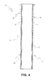
FIG. 4 is a schematic vertical cross-section of another insert sleeve embodying the invention. - As noted above, the impingement openings according to the invention improve heat transfer and increase the effective use of cooling air and/or steam to reduce nozzle and other engine component temperatures. The multiple geometric edges that define an opening have a size and configuration that result in a higher impingement jet velocity and increased heat transfer as compared to round openings with a comparable cross sectional area. The use of such multi-faceted impingement holes allows for greater throughput and a net reduction in metal temperatures. It has also been found that the star-like configuration has the capability to develop a vortex flow field that provides for a more efficient mixing of the cooling air before it impacts the vane. The more efficient mixing allows for a higher velocity distribution of the cooling air, and hence higher heat transfer between the fluid and the surface.
- The general form of an exemplary insert sleeve is illustrated in
FIGS. 1-3 .FIG. 1 shows a sleeve for the leading edge cavity, whereasFIGS. 2 and 3 illustrate an exemplary sleeve specifically forcavity 17 inFIG. 1 . In the embodiment ofFIG. 1 ,nozzle vane 10 includes a plurality ofintegral cavities insert sleeves - In the
leading edge cavity 30 ofFIG. 1 , the forward edge ofinsert sleeve 31 has a curved configuration with the side walls generally corresponding in shape to the side walls ofmulti-faceted cavity 30. The side walls of the insert sleeve include a plurality of impingement openings along a portion of the entire length. As shown, the impingement openings have a multi-faceted, i.e., serrated, configuration (also shown as enlarge impingement opening 40). Theback side 32 ofinsert sleeve 31 does not include any impingement openings. Similarly, in theaft cavities insert sleeves insert sleeves FIG. 1 is only one example of the type of opening contemplated by the invention. Other geometric configurations with uniform and non-uniform serrations could be used, such as multi-pointed stars, chevron type holes, "spiked" openings and the like. - The sleeves in
cavities - As
FIG. 1 also illustrates, the insert sleeves include impingement cooling openings disposed on an upstream part of the sleeve. The other, downstream part is substantially imperforate and does not contain holes but instead acts as a blocking mechanism by reducing the coolant flow area in the area between the insert sleeve and the cavity interior wall. Seesleeve gap 50. The design using the new impingement openings thus allows for improved mixing, increased impingement air jet velocities as the air moves from the opening to the target surface, and ultimately better heat transfer coefficients along the entire length of the vane. The new openings also reduce unintended post impingement coolant cross-flow. -
Insert sleeve 23 illustrated inFIGS. 1 and2 comprises an elongated sleeve having an open lower end with a marginal flange for connecting to the opening of a corresponding cavity, e.g.,cavity 17 inFIG. 1 . Theside walls sleeve 23 include a plurality of serratedimpingement cooling openings FIG. 3 . Impingement cooling holes 52, 53 are defined along firstupstream sleeve portions Downstream sleeve portions cavity 17 by defining fluid flow channels that benefit from post impingement cooling flow via the spaces defined adjacent the first impingement openings in the sleeve. - As illustrated in
FIG. 2 , the extent of the portions of the sleeve on which the impingement holes 52 and 53 have been provided depends upon whether the insert sleeve side wall faces the pressure side or suction side of the airfoil. While the extent of the impingement holes on each side can be varied as deemed necessary or desirable, the extent of the impingement is preferably greater on the pressure side of the sleeve than on the suction side. - Referring to
FIG. 4 , insertsleeve 60 is provided invane cavity 19. The peripheral outline ofinsert sleeve 60 again follows the contour of the cavity and has star-shapedimpingement openings side walls insert sleeve 60 from a plenum and then outwardly throughopenings cavity 19. - The extent of the
insert sleeve 60 with impingement holes 61, 62 depends upon whether the insert sleeve side wall faces the pressure side or suction side of the airfoil. While the extent of the impingement holes on each side can be varied as deemed necessary or desirable to achieve the objectives of the invention, the extent of the holes generally is greater on the pressure side of the insert sleeve than on the suction side. - In
FIG. 4 , the impingement cooling serrated openings are again located inupstream sleeve portions downstream sleeve portions cavity 19. As with the insert sleeve in the leading edge cavity and the return cavities, the upstream portion using the new impingement openings allows for improved mixing, increased impingement air jet velocities and ultimately better heat transfer for those portions of the vane. - While the invention has been described in connection with what is presently considered to be the most practical and preferred embodiment, it is to be understood that the invention is not to be limited to the disclosed embodiment, but on the contrary, is intended to cover various modifications and equivalent arrangements included within the spirit and scope of the appended claims.
Claims (12)
- A nozzle vane (10) for a gas turbine engine, comprising:a vane wall having inner and outer wall surfaces, said wall surfaces being uniformly spaced from one another to define a fluid passageway for a cooling medium;a plurality of cavities (11-17,30) formed by interior wall members disposed between said inner and outer wall surfaces and within said fluid passageway;a plurality of insert cooling sleeves (18-23,31,60) disposed in said discreet cavities defined by said inner and outer wall surfaces and said interior wall members; anda plurality of non-round impingement openings (40,52,53) in each of said insert cooling sleeves, (18-23,31,60) said openings (40,52,53) being sufficient in size and number to accommodate the flow of said cooling medium into the interior of said fluid passageway.
- A nozzle vane according to claim 1, wherein said non-round openings (40) in said insert cooling sleeves (60) comprise generally star-like fluid passages (61,62) having a radial array of projections emanating from the center of each opening (40).
- A nozzle vane according to claim 1, wherein said non-round openings (40) in said insert cooling sleeves (18-23,31) define an array of generally uniform, equidistant fluid pathways emanating from the center of each opening (40).
- A nozzle vane according to any of claims 1 to 3, wherein said non-round openings (40) in said insert cooling sleeves (18-23,31,60) are disposed substantially along the length of each insert sleeve (18-23,31,60).
- A nozzle vane according to any of claims 1 to 4, wherein said non-round openings (40) in said insert cooling sleeves (18-23,31,60) comprise a chevron configuration.
- A nozzle vane according to any of claims 1 to 5, wherein said flow of said cooling medium impinges on said interior wall surfaces of said nozzle.
- A nozzle vane according to any preceding claim, wherein said non-round openings (40) in said insert cooling sleeves (18-23,31,60) are formed in first and second walls of each one of a plurality of insert cooling sleeves (18-23,31,60).
- A nozzle vane according to any preceding claim, wherein said discreet cavities (11-17,30) formed by said insert cooling sleeves (18-23,31,60) have the same general configuration as said interior wall members.
- A nozzle vane according to any preceding claim, wherein said discreet cavities (11-17,30) and said insert sleeves (18-23,31,60) define a specific fluid flow gap for said cooling medium.
- A nozzle vane according to any preceding claim, wherein said discreet cavities (11-17,30) extend lengthwise and parallel to one another in said nozzle vane (10).
- A nozzle vane according to any preceding claim, wherein said cooling medium includes one of compressed air, steam or a mixture of steam and compressed air.
- A nozzle vane according to any preceding claim, wherein the forward edge of said insert sleeve (18-23,31,60) is curved in shape and the side walls (50,51,63,64) of said sleeve generally correspond in shape to the side walls of said cavities (11-17,30).
Applications Claiming Priority (1)
| Application Number | Priority Date | Filing Date | Title |
|---|---|---|---|
| US13/326,372 US9151173B2 (en) | 2011-12-15 | 2011-12-15 | Use of multi-faceted impingement openings for increasing heat transfer characteristics on gas turbine components |
Publications (3)
| Publication Number | Publication Date |
|---|---|
| EP2604800A2 true EP2604800A2 (en) | 2013-06-19 |
| EP2604800A3 EP2604800A3 (en) | 2015-07-22 |
| EP2604800B1 EP2604800B1 (en) | 2018-02-21 |
Family
ID=47297013
Family Applications (1)
| Application Number | Title | Priority Date | Filing Date |
|---|---|---|---|
| EP12196112.2A Not-in-force EP2604800B1 (en) | 2011-12-15 | 2012-12-07 | Nozzle vane for a gas turbine engine |
Country Status (5)
| Country | Link |
|---|---|
| US (1) | US9151173B2 (en) |
| EP (1) | EP2604800B1 (en) |
| JP (1) | JP2013124663A (en) |
| CN (1) | CN103161513B (en) |
| RU (1) | RU2012153930A (en) |
Cited By (1)
| Publication number | Priority date | Publication date | Assignee | Title |
|---|---|---|---|---|
| EP3236010A1 (en) * | 2016-04-21 | 2017-10-25 | Siemens Aktiengesellschaft | Stator vane having a junction tubing |
Families Citing this family (25)
| Publication number | Priority date | Publication date | Assignee | Title |
|---|---|---|---|---|
| US10100666B2 (en) * | 2013-03-29 | 2018-10-16 | General Electric Company | Hot gas path component for turbine system |
| US9849510B2 (en) | 2015-04-16 | 2017-12-26 | General Electric Company | Article and method of forming an article |
| US9976441B2 (en) | 2015-05-29 | 2018-05-22 | General Electric Company | Article, component, and method of forming an article |
| US9995151B2 (en) | 2015-08-17 | 2018-06-12 | General Electric Company | Article and manifold for thermal adjustment of a turbine component |
| US10253986B2 (en) * | 2015-09-08 | 2019-04-09 | General Electric Company | Article and method of forming an article |
| US10087776B2 (en) | 2015-09-08 | 2018-10-02 | General Electric Company | Article and method of forming an article |
| US10739087B2 (en) | 2015-09-08 | 2020-08-11 | General Electric Company | Article, component, and method of forming an article |
| US10815789B2 (en) | 2016-02-13 | 2020-10-27 | General Electric Company | Impingement holes for a turbine engine component |
| US10309228B2 (en) * | 2016-06-09 | 2019-06-04 | General Electric Company | Impingement insert for a gas turbine engine |
| US10450868B2 (en) * | 2016-07-22 | 2019-10-22 | General Electric Company | Turbine rotor blade with coupon having corrugated surface(s) |
| US10443399B2 (en) * | 2016-07-22 | 2019-10-15 | General Electric Company | Turbine vane with coupon having corrugated surface(s) |
| US10436037B2 (en) | 2016-07-22 | 2019-10-08 | General Electric Company | Blade with parallel corrugated surfaces on inner and outer surfaces |
| US10465520B2 (en) | 2016-07-22 | 2019-11-05 | General Electric Company | Blade with corrugated outer surface(s) |
| US10465525B2 (en) | 2016-07-22 | 2019-11-05 | General Electric Company | Blade with internal rib having corrugated surface(s) |
| US10655477B2 (en) | 2016-07-26 | 2020-05-19 | General Electric Company | Turbine components and method for forming turbine components |
| US10577942B2 (en) * | 2016-11-17 | 2020-03-03 | General Electric Company | Double impingement slot cap assembly |
| EP3351341A1 (en) * | 2017-01-23 | 2018-07-25 | Siemens Aktiengesellschaft | Method for producing a cavity in a blade platform |
| US20190277501A1 (en) * | 2018-03-07 | 2019-09-12 | United Technologies Corporation | Slot arrangements for an impingement floatwall film cooling of a turbine engine |
| US11192207B2 (en) | 2018-10-26 | 2021-12-07 | General Electric Company | Additive manufactured object with passage having varying cross-sectional shape |
| US10711620B1 (en) * | 2019-01-14 | 2020-07-14 | General Electric Company | Insert system for an airfoil and method of installing same |
| US11358221B2 (en) * | 2019-09-30 | 2022-06-14 | The Boeing Company | Build part and method of additively manufacturing the build part |
| US11629642B2 (en) | 2019-12-20 | 2023-04-18 | General Electric Company | System and methods for igniting and operating a gas turbine engine with alternative fuels |
| US11959641B2 (en) * | 2020-01-31 | 2024-04-16 | Rtx Corporation | Combustor shell with shaped impingement holes |
| CN112268012B (en) * | 2020-10-10 | 2022-02-11 | 浙江理工大学 | Volute-free centrifugal ventilator impeller with tail wing jet device and working method thereof |
| CN113944516B (en) * | 2021-09-28 | 2024-04-02 | 中国科学院工程热物理研究所 | Composite cooling structure for tip of gas turbine |
Citations (2)
| Publication number | Priority date | Publication date | Assignee | Title |
|---|---|---|---|---|
| EP1247940A1 (en) | 1999-06-15 | 2002-10-09 | Mitsubishi Heavy Industries, Ltd. | Gas turbine stationary blade |
| US6468031B1 (en) | 2000-05-16 | 2002-10-22 | General Electric Company | Nozzle cavity impingement/area reduction insert |
Family Cites Families (37)
| Publication number | Priority date | Publication date | Assignee | Title |
|---|---|---|---|---|
| US1545560A (en) | 1924-08-06 | 1925-07-14 | Heath Spencer | Airplane propeller |
| US1939357A (en) | 1929-02-13 | 1933-12-12 | Bendix Aviat Corp | Hollow blade for turbines |
| US3148954A (en) | 1960-06-13 | 1964-09-15 | Haas Irene | Turbine blade construction |
| GB1565361A (en) | 1976-01-29 | 1980-04-16 | Rolls Royce | Blade or vane for a gas turbine engien |
| GB2119028B (en) | 1982-04-27 | 1985-02-27 | Rolls Royce | Aerofoil for a gas turbine engine |
| US4645415A (en) | 1983-12-23 | 1987-02-24 | United Technologies Corporation | Air cooler for providing buffer air to a bearing compartment |
| FR2581708B1 (en) | 1985-05-09 | 1989-04-28 | Snecma | COVER FOR TURBOREACTOR BLADE BLADE ATTACK EDGE |
| US4669957A (en) | 1985-12-23 | 1987-06-02 | United Technologies Corporation | Film coolant passage with swirl diffuser |
| FR2599425B1 (en) | 1986-05-28 | 1988-08-05 | Alsthom | PROTECTIVE PLATE FOR TITANIUM BLADE AND METHOD OF BRAZING SUCH A PLATE. |
| US5667359A (en) | 1988-08-24 | 1997-09-16 | United Technologies Corp. | Clearance control for the turbine of a gas turbine engine |
| US5210946A (en) | 1992-06-26 | 1993-05-18 | Hudson Products Corporation | Leading edge protection for fan blade |
| JP3651490B2 (en) | 1993-12-28 | 2005-05-25 | 株式会社東芝 | Turbine cooling blade |
| US5634766A (en) | 1994-08-23 | 1997-06-03 | General Electric Co. | Turbine stator vane segments having combined air and steam cooling circuits |
| GB2293631B (en) | 1994-09-30 | 1998-09-09 | Gen Electric | Composite fan blade trailing edge reinforcement |
| US5685693A (en) | 1995-03-31 | 1997-11-11 | General Electric Co. | Removable inner turbine shell with bucket tip clearance control |
| US5779437A (en) | 1996-10-31 | 1998-07-14 | Pratt & Whitney Canada Inc. | Cooling passages for airfoil leading edge |
| JPH1144498A (en) * | 1997-05-30 | 1999-02-16 | Showa Alum Corp | Flat porous tube for heat exchanger and heat exchanger using the tube |
| US6238182B1 (en) | 1999-02-19 | 2001-05-29 | Meyer Tool, Inc. | Joint for a turbine component |
| US6183192B1 (en) | 1999-03-22 | 2001-02-06 | General Electric Company | Durable turbine nozzle |
| JP3322857B2 (en) | 1999-11-30 | 2002-09-09 | モルデック株式会社 | Insert molding method for receptacle connector |
| US6428273B1 (en) * | 2001-01-05 | 2002-08-06 | General Electric Company | Truncated rib turbine nozzle |
| JP4508432B2 (en) | 2001-01-09 | 2010-07-21 | 三菱重工業株式会社 | Gas turbine cooling structure |
| EP1275818B1 (en) * | 2001-07-13 | 2006-08-16 | ALSTOM Technology Ltd | Gas turbine component with cooling holes |
| US6742991B2 (en) | 2002-07-11 | 2004-06-01 | Mitsubishi Heavy Industries, Ltd. | Turbine blade and gas turbine |
| JP4191578B2 (en) | 2003-11-21 | 2008-12-03 | 三菱重工業株式会社 | Turbine cooling blade of gas turbine engine |
| US7008178B2 (en) * | 2003-12-17 | 2006-03-07 | General Electric Company | Inboard cooled nozzle doublet |
| US20050265840A1 (en) | 2004-05-27 | 2005-12-01 | Levine Jeffrey R | Cooled rotor blade with leading edge impingement cooling |
| US7374401B2 (en) * | 2005-03-01 | 2008-05-20 | General Electric Company | Bell-shaped fan cooling holes for turbine airfoil |
| EP2115272A1 (en) * | 2007-01-04 | 2009-11-11 | Ansaldo Energia S.P.A. | Spacer for gas turbine blade insert |
| DE102007018061A1 (en) * | 2007-04-17 | 2008-10-23 | Rolls-Royce Deutschland Ltd & Co Kg | Gas turbine combustion chamber wall |
| JP2009162119A (en) * | 2008-01-08 | 2009-07-23 | Ihi Corp | Turbine blade cooling structure |
| US20100037620A1 (en) | 2008-08-15 | 2010-02-18 | General Electric Company, Schenectady | Impingement and effusion cooled combustor component |
| US8142137B2 (en) * | 2008-11-26 | 2012-03-27 | Alstom Technology Ltd | Cooled gas turbine vane assembly |
| CH701031A1 (en) * | 2009-05-15 | 2010-11-15 | Alstom Technology Ltd | The method for refurbishing a turbine blade. |
| US20110097191A1 (en) * | 2009-10-28 | 2011-04-28 | General Electric Company | Method and structure for cooling airfoil surfaces using asymmetric chevron film holes |
| US8529193B2 (en) * | 2009-11-25 | 2013-09-10 | Honeywell International Inc. | Gas turbine engine components with improved film cooling |
| FR2955145B1 (en) * | 2010-01-14 | 2012-02-03 | Snecma | HIGH PRESSURE TURBINE DISPENSER OF A TURBOREACTOR |
-
2011
- 2011-12-15 US US13/326,372 patent/US9151173B2/en not_active Expired - Fee Related
-
2012
- 2012-12-07 EP EP12196112.2A patent/EP2604800B1/en not_active Not-in-force
- 2012-12-10 JP JP2012268914A patent/JP2013124663A/en active Pending
- 2012-12-14 RU RU2012153930/06A patent/RU2012153930A/en not_active Application Discontinuation
- 2012-12-14 CN CN201210545238.3A patent/CN103161513B/en not_active Expired - Fee Related
Patent Citations (2)
| Publication number | Priority date | Publication date | Assignee | Title |
|---|---|---|---|---|
| EP1247940A1 (en) | 1999-06-15 | 2002-10-09 | Mitsubishi Heavy Industries, Ltd. | Gas turbine stationary blade |
| US6468031B1 (en) | 2000-05-16 | 2002-10-22 | General Electric Company | Nozzle cavity impingement/area reduction insert |
Cited By (2)
| Publication number | Priority date | Publication date | Assignee | Title |
|---|---|---|---|---|
| EP3236010A1 (en) * | 2016-04-21 | 2017-10-25 | Siemens Aktiengesellschaft | Stator vane having a junction tubing |
| WO2017182423A1 (en) * | 2016-04-21 | 2017-10-26 | Siemens Aktiengesellschaft | Guide vane comprising a connecting tube and method for producing a guide vane |
Also Published As
| Publication number | Publication date |
|---|---|
| CN103161513B (en) | 2017-03-01 |
| RU2012153930A (en) | 2014-06-20 |
| EP2604800A3 (en) | 2015-07-22 |
| US9151173B2 (en) | 2015-10-06 |
| US20130156549A1 (en) | 2013-06-20 |
| CN103161513A (en) | 2013-06-19 |
| JP2013124663A (en) | 2013-06-24 |
| EP2604800B1 (en) | 2018-02-21 |
Similar Documents
| Publication | Publication Date | Title |
|---|---|---|
| EP2604800B1 (en) | Nozzle vane for a gas turbine engine | |
| US7121787B2 (en) | Turbine nozzle trailing edge cooling configuration | |
| US7497655B1 (en) | Turbine airfoil with near-wall impingement and vortex cooling | |
| CA2562584C (en) | Turbine nozzle triplet with differential vane cooling | |
| EP1327747B1 (en) | Crossover cooled airfoil trailing edge | |
| EP1106781B1 (en) | Coolable vane or blade for a turbomachine | |
| JP5356007B2 (en) | Duplex turbine nozzle | |
| JP5723101B2 (en) | Gas turbine engine temperature management method and apparatus | |
| US6200087B1 (en) | Pressure compensated turbine nozzle | |
| JP2005180439A (en) | Frequency regulation type pin bank of turbine blade | |
| US6183198B1 (en) | Airfoil isolated leading edge cooling | |
| US6468031B1 (en) | Nozzle cavity impingement/area reduction insert | |
| US6929446B2 (en) | Counterbalanced flow turbine nozzle | |
| US8613597B1 (en) | Turbine blade with trailing edge cooling | |
| JP2007514888A (en) | Cooling turbine vane platform | |
| GB2460936A (en) | Turbine airfoil cooling | |
| JP2009002340A (en) | Differently cooling type turbine nozzle | |
| JP2011522158A (en) | Turbine airfoil with metering cooling cavity | |
| US20130084191A1 (en) | Turbine blade with impingement cavity cooling including pin fins | |
| US11199099B2 (en) | Gas turbine engines with improved airfoil dust removal | |
| US20090081029A1 (en) | Gas Turbine Component with Reduced Cooling Air Requirement | |
| JP2011208624A (en) | Cooling structure for high-temperature member | |
| US20210246810A1 (en) | Turbine nozzle segment and a turbinne nozzle comprising such a turbine nozzle segment |
Legal Events
| Date | Code | Title | Description |
|---|---|---|---|
| PUAI | Public reference made under article 153(3) epc to a published international application that has entered the european phase |
Free format text: ORIGINAL CODE: 0009012 |
|
| AK | Designated contracting states |
Kind code of ref document: A2 Designated state(s): AL AT BE BG CH CY CZ DE DK EE ES FI FR GB GR HR HU IE IS IT LI LT LU LV MC MK MT NL NO PL PT RO RS SE SI SK SM TR |
|
| AX | Request for extension of the european patent |
Extension state: BA ME |
|
| PUAL | Search report despatched |
Free format text: ORIGINAL CODE: 0009013 |
|
| AK | Designated contracting states |
Kind code of ref document: A3 Designated state(s): AL AT BE BG CH CY CZ DE DK EE ES FI FR GB GR HR HU IE IS IT LI LT LU LV MC MK MT NL NO PL PT RO RS SE SI SK SM TR |
|
| AX | Request for extension of the european patent |
Extension state: BA ME |
|
| RIC1 | Information provided on ipc code assigned before grant |
Ipc: F01D 9/02 20060101AFI20150616BHEP Ipc: F01D 5/18 20060101ALI20150616BHEP Ipc: F01D 9/04 20060101ALI20150616BHEP Ipc: F01D 9/06 20060101ALI20150616BHEP |
|
| 17P | Request for examination filed |
Effective date: 20160122 |
|
| RBV | Designated contracting states (corrected) |
Designated state(s): AL AT BE BG CH CY CZ DE DK EE ES FI FR GB GR HR HU IE IS IT LI LT LU LV MC MK MT NL NO PL PT RO RS SE SI SK SM TR |
|
| GRAP | Despatch of communication of intention to grant a patent |
Free format text: ORIGINAL CODE: EPIDOSNIGR1 |
|
| INTG | Intention to grant announced |
Effective date: 20170808 |
|
| GRAS | Grant fee paid |
Free format text: ORIGINAL CODE: EPIDOSNIGR3 |
|
| GRAA | (expected) grant |
Free format text: ORIGINAL CODE: 0009210 |
|
| AK | Designated contracting states |
Kind code of ref document: B1 Designated state(s): AL AT BE BG CH CY CZ DE DK EE ES FI FR GB GR HR HU IE IS IT LI LT LU LV MC MK MT NL NO PL PT RO RS SE SI SK SM TR |
|
| REG | Reference to a national code |
Ref country code: GB Ref legal event code: FG4D |
|
| REG | Reference to a national code |
Ref country code: CH Ref legal event code: EP |
|
| REG | Reference to a national code |
Ref country code: AT Ref legal event code: REF Ref document number: 971945 Country of ref document: AT Kind code of ref document: T Effective date: 20180315 |
|
| REG | Reference to a national code |
Ref country code: IE Ref legal event code: FG4D |
|
| REG | Reference to a national code |
Ref country code: DE Ref legal event code: R096 Ref document number: 602012042986 Country of ref document: DE |
|
| REG | Reference to a national code |
Ref country code: NL Ref legal event code: MP Effective date: 20180221 |
|
| REG | Reference to a national code |
Ref country code: LT Ref legal event code: MG4D |
|
| REG | Reference to a national code |
Ref country code: AT Ref legal event code: MK05 Ref document number: 971945 Country of ref document: AT Kind code of ref document: T Effective date: 20180221 |
|
| PG25 | Lapsed in a contracting state [announced via postgrant information from national office to epo] |
Ref country code: FI Free format text: LAPSE BECAUSE OF FAILURE TO SUBMIT A TRANSLATION OF THE DESCRIPTION OR TO PAY THE FEE WITHIN THE PRESCRIBED TIME-LIMIT Effective date: 20180221 Ref country code: HR Free format text: LAPSE BECAUSE OF FAILURE TO SUBMIT A TRANSLATION OF THE DESCRIPTION OR TO PAY THE FEE WITHIN THE PRESCRIBED TIME-LIMIT Effective date: 20180221 Ref country code: CY Free format text: LAPSE BECAUSE OF FAILURE TO SUBMIT A TRANSLATION OF THE DESCRIPTION OR TO PAY THE FEE WITHIN THE PRESCRIBED TIME-LIMIT Effective date: 20180221 Ref country code: LT Free format text: LAPSE BECAUSE OF FAILURE TO SUBMIT A TRANSLATION OF THE DESCRIPTION OR TO PAY THE FEE WITHIN THE PRESCRIBED TIME-LIMIT Effective date: 20180221 Ref country code: NL Free format text: LAPSE BECAUSE OF FAILURE TO SUBMIT A TRANSLATION OF THE DESCRIPTION OR TO PAY THE FEE WITHIN THE PRESCRIBED TIME-LIMIT Effective date: 20180221 Ref country code: NO Free format text: LAPSE BECAUSE OF FAILURE TO SUBMIT A TRANSLATION OF THE DESCRIPTION OR TO PAY THE FEE WITHIN THE PRESCRIBED TIME-LIMIT Effective date: 20180521 Ref country code: ES Free format text: LAPSE BECAUSE OF FAILURE TO SUBMIT A TRANSLATION OF THE DESCRIPTION OR TO PAY THE FEE WITHIN THE PRESCRIBED TIME-LIMIT Effective date: 20180221 |
|
| PG25 | Lapsed in a contracting state [announced via postgrant information from national office to epo] |
Ref country code: BG Free format text: LAPSE BECAUSE OF FAILURE TO SUBMIT A TRANSLATION OF THE DESCRIPTION OR TO PAY THE FEE WITHIN THE PRESCRIBED TIME-LIMIT Effective date: 20180521 Ref country code: AT Free format text: LAPSE BECAUSE OF FAILURE TO SUBMIT A TRANSLATION OF THE DESCRIPTION OR TO PAY THE FEE WITHIN THE PRESCRIBED TIME-LIMIT Effective date: 20180221 Ref country code: RS Free format text: LAPSE BECAUSE OF FAILURE TO SUBMIT A TRANSLATION OF THE DESCRIPTION OR TO PAY THE FEE WITHIN THE PRESCRIBED TIME-LIMIT Effective date: 20180221 Ref country code: LV Free format text: LAPSE BECAUSE OF FAILURE TO SUBMIT A TRANSLATION OF THE DESCRIPTION OR TO PAY THE FEE WITHIN THE PRESCRIBED TIME-LIMIT Effective date: 20180221 Ref country code: SE Free format text: LAPSE BECAUSE OF FAILURE TO SUBMIT A TRANSLATION OF THE DESCRIPTION OR TO PAY THE FEE WITHIN THE PRESCRIBED TIME-LIMIT Effective date: 20180221 Ref country code: GR Free format text: LAPSE BECAUSE OF FAILURE TO SUBMIT A TRANSLATION OF THE DESCRIPTION OR TO PAY THE FEE WITHIN THE PRESCRIBED TIME-LIMIT Effective date: 20180522 |
|
| PG25 | Lapsed in a contracting state [announced via postgrant information from national office to epo] |
Ref country code: EE Free format text: LAPSE BECAUSE OF FAILURE TO SUBMIT A TRANSLATION OF THE DESCRIPTION OR TO PAY THE FEE WITHIN THE PRESCRIBED TIME-LIMIT Effective date: 20180221 Ref country code: PL Free format text: LAPSE BECAUSE OF FAILURE TO SUBMIT A TRANSLATION OF THE DESCRIPTION OR TO PAY THE FEE WITHIN THE PRESCRIBED TIME-LIMIT Effective date: 20180221 Ref country code: RO Free format text: LAPSE BECAUSE OF FAILURE TO SUBMIT A TRANSLATION OF THE DESCRIPTION OR TO PAY THE FEE WITHIN THE PRESCRIBED TIME-LIMIT Effective date: 20180221 Ref country code: AL Free format text: LAPSE BECAUSE OF FAILURE TO SUBMIT A TRANSLATION OF THE DESCRIPTION OR TO PAY THE FEE WITHIN THE PRESCRIBED TIME-LIMIT Effective date: 20180221 |
|
| REG | Reference to a national code |
Ref country code: DE Ref legal event code: R097 Ref document number: 602012042986 Country of ref document: DE |
|
| PG25 | Lapsed in a contracting state [announced via postgrant information from national office to epo] |
Ref country code: DK Free format text: LAPSE BECAUSE OF FAILURE TO SUBMIT A TRANSLATION OF THE DESCRIPTION OR TO PAY THE FEE WITHIN THE PRESCRIBED TIME-LIMIT Effective date: 20180221 Ref country code: SK Free format text: LAPSE BECAUSE OF FAILURE TO SUBMIT A TRANSLATION OF THE DESCRIPTION OR TO PAY THE FEE WITHIN THE PRESCRIBED TIME-LIMIT Effective date: 20180221 Ref country code: SM Free format text: LAPSE BECAUSE OF FAILURE TO SUBMIT A TRANSLATION OF THE DESCRIPTION OR TO PAY THE FEE WITHIN THE PRESCRIBED TIME-LIMIT Effective date: 20180221 Ref country code: CZ Free format text: LAPSE BECAUSE OF FAILURE TO SUBMIT A TRANSLATION OF THE DESCRIPTION OR TO PAY THE FEE WITHIN THE PRESCRIBED TIME-LIMIT Effective date: 20180221 |
|
| PLBE | No opposition filed within time limit |
Free format text: ORIGINAL CODE: 0009261 |
|
| STAA | Information on the status of an ep patent application or granted ep patent |
Free format text: STATUS: NO OPPOSITION FILED WITHIN TIME LIMIT |
|
| 26N | No opposition filed |
Effective date: 20181122 |
|
| PG25 | Lapsed in a contracting state [announced via postgrant information from national office to epo] |
Ref country code: SI Free format text: LAPSE BECAUSE OF FAILURE TO SUBMIT A TRANSLATION OF THE DESCRIPTION OR TO PAY THE FEE WITHIN THE PRESCRIBED TIME-LIMIT Effective date: 20180221 |
|
| REG | Reference to a national code |
Ref country code: DE Ref legal event code: R119 Ref document number: 602012042986 Country of ref document: DE |
|
| REG | Reference to a national code |
Ref country code: CH Ref legal event code: PL |
|
| GBPC | Gb: european patent ceased through non-payment of renewal fee |
Effective date: 20181207 |
|
| PG25 | Lapsed in a contracting state [announced via postgrant information from national office to epo] |
Ref country code: LU Free format text: LAPSE BECAUSE OF NON-PAYMENT OF DUE FEES Effective date: 20181207 Ref country code: MC Free format text: LAPSE BECAUSE OF FAILURE TO SUBMIT A TRANSLATION OF THE DESCRIPTION OR TO PAY THE FEE WITHIN THE PRESCRIBED TIME-LIMIT Effective date: 20180221 |
|
| REG | Reference to a national code |
Ref country code: IE Ref legal event code: MM4A |
|
| REG | Reference to a national code |
Ref country code: BE Ref legal event code: MM Effective date: 20181231 |
|
| PG25 | Lapsed in a contracting state [announced via postgrant information from national office to epo] |
Ref country code: DE Free format text: LAPSE BECAUSE OF NON-PAYMENT OF DUE FEES Effective date: 20190702 Ref country code: IT Free format text: LAPSE BECAUSE OF NON-PAYMENT OF DUE FEES Effective date: 20181207 Ref country code: FR Free format text: LAPSE BECAUSE OF NON-PAYMENT OF DUE FEES Effective date: 20181231 Ref country code: IE Free format text: LAPSE BECAUSE OF NON-PAYMENT OF DUE FEES Effective date: 20181207 |
|
| PG25 | Lapsed in a contracting state [announced via postgrant information from national office to epo] |
Ref country code: BE Free format text: LAPSE BECAUSE OF NON-PAYMENT OF DUE FEES Effective date: 20181231 |
|
| PG25 | Lapsed in a contracting state [announced via postgrant information from national office to epo] |
Ref country code: LI Free format text: LAPSE BECAUSE OF NON-PAYMENT OF DUE FEES Effective date: 20181231 Ref country code: CH Free format text: LAPSE BECAUSE OF NON-PAYMENT OF DUE FEES Effective date: 20181231 Ref country code: GB Free format text: LAPSE BECAUSE OF NON-PAYMENT OF DUE FEES Effective date: 20181207 |
|
| PG25 | Lapsed in a contracting state [announced via postgrant information from national office to epo] |
Ref country code: MT Free format text: LAPSE BECAUSE OF NON-PAYMENT OF DUE FEES Effective date: 20181207 |
|
| PG25 | Lapsed in a contracting state [announced via postgrant information from national office to epo] |
Ref country code: TR Free format text: LAPSE BECAUSE OF FAILURE TO SUBMIT A TRANSLATION OF THE DESCRIPTION OR TO PAY THE FEE WITHIN THE PRESCRIBED TIME-LIMIT Effective date: 20180221 |
|
| PG25 | Lapsed in a contracting state [announced via postgrant information from national office to epo] |
Ref country code: PT Free format text: LAPSE BECAUSE OF FAILURE TO SUBMIT A TRANSLATION OF THE DESCRIPTION OR TO PAY THE FEE WITHIN THE PRESCRIBED TIME-LIMIT Effective date: 20180221 |
|
| PG25 | Lapsed in a contracting state [announced via postgrant information from national office to epo] |
Ref country code: HU Free format text: LAPSE BECAUSE OF FAILURE TO SUBMIT A TRANSLATION OF THE DESCRIPTION OR TO PAY THE FEE WITHIN THE PRESCRIBED TIME-LIMIT; INVALID AB INITIO Effective date: 20121207 Ref country code: MK Free format text: LAPSE BECAUSE OF NON-PAYMENT OF DUE FEES Effective date: 20180221 |
|
| PG25 | Lapsed in a contracting state [announced via postgrant information from national office to epo] |
Ref country code: IS Free format text: LAPSE BECAUSE OF FAILURE TO SUBMIT A TRANSLATION OF THE DESCRIPTION OR TO PAY THE FEE WITHIN THE PRESCRIBED TIME-LIMIT Effective date: 20180621 |