EP2604734A1 - Lighting apparatus for laundry machines - Google Patents
Lighting apparatus for laundry machines Download PDFInfo
- Publication number
- EP2604734A1 EP2604734A1 EP11193995.5A EP11193995A EP2604734A1 EP 2604734 A1 EP2604734 A1 EP 2604734A1 EP 11193995 A EP11193995 A EP 11193995A EP 2604734 A1 EP2604734 A1 EP 2604734A1
- Authority
- EP
- European Patent Office
- Prior art keywords
- light
- drum
- emitting element
- laundry machine
- stationary
- Prior art date
- Legal status (The legal status is an assumption and is not a legal conclusion. Google has not performed a legal analysis and makes no representation as to the accuracy of the status listed.)
- Withdrawn
Links
Images



Classifications
-
- D—TEXTILES; PAPER
- D06—TREATMENT OF TEXTILES OR THE LIKE; LAUNDERING; FLEXIBLE MATERIALS NOT OTHERWISE PROVIDED FOR
- D06F—LAUNDERING, DRYING, IRONING, PRESSING OR FOLDING TEXTILE ARTICLES
- D06F37/00—Details specific to washing machines covered by groups D06F21/00 - D06F25/00
- D06F37/02—Rotary receptacles, e.g. drums
- D06F37/04—Rotary receptacles, e.g. drums adapted for rotation or oscillation about a horizontal or inclined axis
- D06F37/10—Doors; Securing means therefor
-
- D—TEXTILES; PAPER
- D06—TREATMENT OF TEXTILES OR THE LIKE; LAUNDERING; FLEXIBLE MATERIALS NOT OTHERWISE PROVIDED FOR
- D06F—LAUNDERING, DRYING, IRONING, PRESSING OR FOLDING TEXTILE ARTICLES
- D06F39/00—Details of washing machines not specific to a single type of machines covered by groups D06F9/00 - D06F27/00
- D06F39/12—Casings; Tubs
- D06F39/14—Doors or covers; Securing means therefor
Definitions
- the present invention generally relates to electric appliances.
- the present invention is referred to laundry machines, such as top-loading washing machines, washing/drying machines and drying machines, both for domestic and professional use. More particularly, the present invention relates to drum lighting for such laundry machines.
- Each household and professional laundry machine - such as washing machine, washing/drying machines and drying machines - typically comprises, among other components, an inner compartment (including a tub generally housing a rotatable drum) accessible by a user ( e.g ., through a proper access door and/or lid) for loading/unloading the laundry.
- an inner compartment including a tub generally housing a rotatable drum
- a user e.g ., through a proper access door and/or lid
- a lighting apparatus which substantially comprises one or more light sources - incandescent light lamps, fluorescent light lamps, discharge light lamps or solid-state lighting devices (e.g., high power LEDs) - acting as corresponding light sources for illuminating the drum, and a supply electric assembly - including electronic circuitry, such as rectifiers and controllers, and electrical wires - for generally supplying an operative electric power (from a power source of the machine) to each light source for the energization thereof.
- a lighting apparatus substantially comprises one or more light sources - incandescent light lamps, fluorescent light lamps, discharge light lamps or solid-state lighting devices (e.g., high power LEDs) - acting as corresponding light sources for illuminating the drum, and a supply electric assembly - including electronic circuitry, such as rectifiers and controllers, and electrical wires - for generally supplying an operative electric power (from a power source of the machine) to each light source for the energization thereof.
- the lighting apparatus may be arranged inside the drum (e.g., in drum walls and/or in lifters inside the drum).
- the Applicant has recognized that the approach providing the light source within the drum is intrinsically difficult to implement - substantially due to the fact that the light source, which is arranged on a portion of the machine ( i.e. , the drum) adapted to rotate with respect to the casing of the machine, has to be electrically connected with the supply electric assembly, which is instead stationary with respect to the casing.
- the supply electric assembly which is instead stationary with respect to the casing.
- laundry items stored inside the drum cover the light source, thus impeding a functional enlightenment of the drum.
- the light source is provided in a frame or hopper provided in correspondence of the loading/unloading opening of the casing and encompassing the tub loading/unloading opening.
- This solution implies several drawbacks, too. For example, properly installing the light source within the frame/hopper is a difficult and time-consuming task. Furthermore, the frame/hopper robustness may be lowered by the insertion of the light source. Moreover, it is difficult to effectively direct the light radiation emitted by the light source towards the inside of the drum.
- the Applicant has handled the problem of devising a satisfactory solution able to provide a satisfactory enlightenment of the inside of the drum, thus facilitating inspection thereof and laundry loading/unloading tasks, at the same time, overcoming the above-discussed drawbacks.
- Such solution is achieved by providing a light-emitting element in a door for opening/closing the drum, which when the door is opened, emits a light radiation substantially able to thoroughly enlighten the inside of the drum.
- the laundry machine comprises an outer casing rotatably housing a drum for accommodating the items to be treated.
- the drum has a drum opening for accessing the inside of the drum for loading/unloading the items, and a door including at least one door flap that is moveable from a closed position, which closes the drum opening, to an open position, which allows access to the inside of the drum.
- the laundry machine comprises a lighting system for enlightening the inside of the drum.
- said lighting system comprises a light-emitting element, mounted to the at least one door flap.
- the light-emitting element may comprise at least one lighting device, generating a light radiation.
- the lighting system may further comprise a stationary element, stationary with respect to the outer casing, adapted to be coupled with the light-emitting element when at least one door flap is in the open position, said stationary element may supply electric power to said light-emitting element.
- the stationary element may be adapted to electrically couple with the light-emitting element without a physical contact.
- the stationary element may be adapted to electrically couple with the light-emitting element by means of a physical contact.
- the lightning system may comprise a stand-alone power supply unit provided in the at least one flap and coupled with the light-emitting element, said stand-alone power supply unit supplying electric power to said light-emitting element.
- the light-emitting element may comprise at least one light-guiding member adapted to transfer light radiation into the inside of the drum
- the lightning system may further comprise a stationary element, stationary with respect to the outer casing, having at least one lightning device adapted to be coupled with the at least one light-guiding member when at least one door flap is in the open position, said at least one lightning device supplying the light radiation to said at least one light-guiding member.
- the light-emitting element may be adjustable in orientation in order to allow a user to manually orienting the light radiation emitted by the light-emitting element.
- the lighting system may further comprise an optical element coupled to the light-emitting element for optimizing the orientation of the light radiation emitted by said light-emitting element.
- the lighting system may further comprise a protective cover for preventing damages to the light-emitting element.
- Another aspect of the present invention provides a method for enlightening the inside of a drum comprised in a laundry machine for treating laundry items.
- the laundry machine has an outer casing rotatably housing a drum for accommodating the items to be treated, the drum having a drum opening for accessing the inside of the drum for loading/unloading the items, and a door having at least one door flap moveable from a closed position, closing the drum opening, to an open position, allowing access to the inside of the drum.
- the method comprises the step of enlightening the inside of the drum.
- said step of enlightening comprises enlightening the inside of the drum by means of a light-emitting element, mounted to the at least one door flap.
- the method may further comprises the step of supplying electric power to the light-emitting element by means of a stationary element stationary with respect to the outer casing.
- the step of supplying electric power to the light-emitting element may further comprise supplying electric power to said light-emitting element only when the at least one door flap is in the open position.
- the method may further comprise the step of supplying light radiation to the light-emitting element by means of a stationary element stationary with respect to the outer casing.
- the step of supplying light radiation to the light-emitting element may further comprise supplying light radiation to said light-emitting element only when the at least one door flap is in the open position.
- FIG.1 and FIG.2 together wherein cross-sectional views of a laundry machine 100, in which an embodiment of the present invention can be applied, are schematically shown.
- the laundry machine 100 is a machine for treating laundry (such has a laundry washing machine, a laundry washing/drying machine, a laundry drying machine etc. ) of the top-loading type.
- the laundry machine 100 comprises a substantially parallelepiped-shaped casing 105 that, preferably, although not necessarily, encloses a substantially cylindrical-shaped tub 110, wherein the laundry is washed, along with any other component of the laundry machine 100 necessary for the operation (e.g., hydraulic, electronic and electromechanical apparatuses well known in the art and, therefore, not shown in the figures nor herein described for sake of conciseness).
- any other component of the laundry machine 100 necessary for the operation e.g., hydraulic, electronic and electromechanical apparatuses well known in the art and, therefore, not shown in the figures nor herein described for sake of conciseness.
- the tub 110 is preferably fixed to a frame (which substantially supports the casing 105 and any other component comprised in the laundry machine, and not shown in the figures), preferably by supporting elastic coils (not illustrated), and shock (and vibration) absorber elements, such as two shock absorbers 112 (which absorb jolts of the tub during operation).
- a frame which substantially supports the casing 105 and any other component comprised in the laundry machine, and not shown in the figures
- shock (and vibration) absorber elements such as two shock absorbers 112 (which absorb jolts of the tub during operation).
- the tub 110 houses a substantially cylindrical-shaped rotating drum 115, which, in operation, rotates about an axis A in order to tumble the laundry to be washed.
- baffles or lifters 120 are mounted on a drum wall 122 (parallel to a drum rotation axis A) in the inside of the drum 115 for enhancing the tumbling action performed in operation by the same.
- an opening 124 is advantageously provided on the top of the washing machine 100.
- the opening 124 is closable by a lid 125, which is preferably, although not necessarily, hingeably connected to the casing 105 by means of a hinge 130.
- the lid 125 is able to pivot from a closed position (shown in FIG.1 ) - wherein the lid 125 closes the opening 124, impeding the access to the tub 110- to an open position (shown in FIG.2 ) - wherein the lid 125 is pivoted to an angle, preferably, equal to, or greater than, 90° with respect to the closed position, allowing the access to the tub 110.
- a drum opening is provided in the drum wall 122 and a door 135 is provided for closing the same during operation.
- the door 135 comprises a first flap 140a and a second flap 140b.
- the first flap 140a is hinged to the drum 115 by a first flap hinge 145a
- the second flap 140b is hinged to the drum 115 by a second flap hinge 145b.
- door 135 may comprise a single flap; the following description refers to a door comprising two flaps, but it can as well be applied to a door comprising a single flap (for example when, in the following, reference is made to the "first flap 140a", it can be read also as "single flap” in case the door 135 comprises only a single flap).
- the laundry machine 100 In order to have the door 135 in an open position (shown in FIG.2 ), the laundry machine 100, at the end of the operation, preferably aligns the door 135 with the opening 124 - alternatively or in addition, the user may align the door 135 with the opening 124 manually -; then the interlocking elements 150 have to be unlocked; lastly, the user has to pivot both the first and second flaps 140a and 140b until they abuts - or reach a predetermined minimum distance from - lateral sidewalls 155 of the opening 124.
- the inside of the drum 115 is accessible (through the drum opening) by the user for loading/unloading the laundry stored therein.
- a user interface 160 for the selection of laundry treatment parameters (e.g., a temperature of a treatment fluid, a maximum rotation speed of the drum 115, etc. ), is provided on the top of the casing 105.
- laundry treatment parameters e.g., a temperature of a treatment fluid, a maximum rotation speed of the drum 115, etc.
- a lighting system is provided for enlightening the inside of the drum (preferably, when the drum door is in the open position).
- the lighting system comprises a light-emitting element provided on at least one flap of the door of the drum, for lighting the inside of the drum, when the door of the drum is in the open position.
- the light-emitting element is stationary with respect to the door of the drum, thus the former rotates - with respect to the casing - together with the latter during the operation of the laundry machine 100.
- a light-emitting element 165 - depicted with a dashed line in the figures - is provided on the first flap 140a of the door 135 and preferably, although not limitatively, is protected by a protective cover 170 (as will described in greater detail in the following).
- the light-emitting element 165 may be activated ( i.e ., to emit a light radiation) when the door 135 is in the open position, with the first flap 140a that abuts, or comes close to ( i.e., at a minimum distance), a portion of the sidewall 155.
- the light-emitting element 165 may comprise any suitable lighting device, such as an incandescent light lamp, a fluorescent light lamp, a discharge light lamp or a solid-state lighting device (e.g., a LED - Light-Emitting Diode). It should be noted that the light-emitting element 165 might comprise more than just one of the lighting devices listed above (e.g., the light-emitting element 165 may comprise a plurality of LEDs in a strip or a ring arrangement) in order to obtain a desired illumination intensity ( i.e ., able to grant a satisfactory enlightenment of the drum 115).
- a desired illumination intensity i.e ., able to grant a satisfactory enlightenment of the drum 115.
- light-emitting element has not to be interpreted only as a lamp or a similar "light-generating” device, but it refer to any device adapted to emit light, for example the edge of an optical fiber, or of a lightguide (for example the free edge of a cylinder made of transparent plastics or glass).
- the lightning system may comprise a stationary element fixed to the frame of the laundry machine. Therefore, such stationary element results, preferably, stationary with respect to the casing of the laundry machine.
- the stationary element is adapted to supply an electric power to the light-emitting element (as will be described in greater detail in the following).
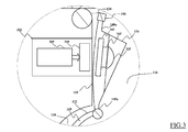
- FIG.3 there is schematically shown a cross-sectional view of an enlarged portion of the laundry machine 100 of FIG.2 according to an embodiment of the present invention.
- a stationary element 302 is adapted to supply electric power to the light-emitting element 165, with the latter that may, advantageously, be coupled with the former (as will be discussed below) when the drum door 135 is in the open position.
- the stationary element is positioned (fixed to the frame of the laundry machine 100) substantially behind the portion of the sidewall 115 to which the first flap 140a abuts, or comes close.
- the stationary element 302 and the light-emitting element 165 may be coupled to one another by means of a contact-less (or wireless) coupling.
- the stationary element 302 may advantageously comprise a power supply unit 305.
- the power supply unit 305 receives electric power from a power source, such as the mains (not shown in the figures), a power circuit (not shown in the figures) of the laundry machine 100 or a battery arrangement (which may be provided within the stationary element 302, not shown) and, in its turns, provides suitable (AC) voltages and currents to a transmission circuit 310.
- the transmission circuit 310 is adapted to transfer electric power by means of an electromagnetic wave (for example, by comprising a radio-frequency transmitter or a wire winding) to the light-emitting element 165.
- the power supply unit 305 and the transmission circuit 310 may be advantageously integrated in a single electronic component.
- the lighting system may comprise a receiver circuit 315 (which comprises a radio-frequency receiver or a corresponding coupled wire winding) provided in the first door flap 140a and electrically connected to the light-emitting element 165.
- the lighting system also comprises an optical element, such as a lens 325 coupled to the light-emitting element 165 in order to optimize the orientation of the light radiation emitted by the same.
- the protective cover 170 may advantageously be provided in the lighting system for preventing damages to the light-emitting element 165 and to the lens 325 ( i. e., elements of the lighting system exposed inside the drum).
- the transmission circuit 310 transfers electric power (by means of the electromagnetic wave) to the receiver circuit 315, which is adapted to properly provide such received electric power (i.e ., as suitable voltages and currents) to the light-emitting element 165 connected to the same.
- the receiver circuit 315 and the light-emitting element 165 are mounted in an hermetically-sealed portion of the first door flap 140a, in order to protect them from liquid and/or moisture present in the tub 110 during the laundry machine 100 operation.
- the lens 325 is, preferably, coupled with the light-emitting element 165 in order to optimize the orientation of the light radiation emitted by the same inside the drum 115. In this way, the inside of the drum 115 is thoroughly well lit, thus allowing easier loading/unloading operations.
- the lens 325 is made, preferably, of a durable and temperature-resistant transparent material, such as borosilicate glass (e.g., Pyrex ®) or polymethyl methacrylate ( e.g., Plexiglas ®).
- the lens 325 may be omitted and the light-emitting portion of the light-emitting element 165 may be, at least partly, directly exposed towards the inside of the drum 115.
- the protective cover 170 is adapted to prevent damages to the lens 325, the light-emitting element 165 and the receiver circuit 315, especially during the operation of the laundry machine 100.
- the protective cover 170 may also provide preliminary orientation to the light radiation emitted by the light-emitting element 165; for example, the protective cover 170 may be formed in such a way to shield the user from being directly hit by the light radiation emitted by the light-emitting element 165, thus preventing glare and dazzling effects.
- the protective cover 170 may be made of any suitable material for the use in the drum 115 (such as metal or plastic) and may be formed integral with the first flap 140a.
- an internal portion of the protective cover 170 could be treated in order to reflect the light emitted by the light-emitting element 165, thus achieving a better concentration of the light radiation toward the inside of the drum 115.
- the internal portion of the protective cover 170 could be polished (if made of metal) or covered with a light reflecting coating (e.g., enamel painting).
- the light-emitting element 165 (and/or the lens 325) may advantageously be made adjustable in orientation in such a way to allow the user to manually adjust an orientation of the light radiation emitted by the same according to her/his needs.
- the light-emitting element 165 may advantageously be telescopic or comprise telescopic portions, in order to be extendable towards the inside of the drum 115 to a predetermined extension; alternatively or in addition, the light-emitting element 165 could be made rotatable about a predetermined rotation axis.
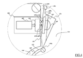
- FIG.4 there is schematically shown a cross-sectional view of an enlarged portion of the laundry machine 100 of FIG.2 with a lightning system according to another embodiment of the present invention.
- the embodiment depicted in the figure differs from the one described in FIG.3 substantially in the fact that electric power is transferred from a stationary element 402 to the light-emitting source 165 through a physical contact (i.e., a wired electrical connection).
- a physical contact i.e., a wired electrical connection
- the stationary element 402 comprises an electric power source 405, which provides voltages and currents to a transmission circuit 410 (clearly the electric power source 405 and the transmission circuit 410 may be advantageously integrated in a single electronic component).
- the power supply unit 405 receives electric power from a power source, such as the mains (not shown in the figures), a power circuit (not shown in the figures) of the laundry machine 100 or a battery arrangement (which may be provided within the stationary element 402, not shown).
- the transmission circuit 410 advantageously comprises first contact elements 415a (e.g., pins, needles, etc.; two shown in the figure) that are advantageously adapted to engage corresponding second contact elements 415b (e.g., pads for the pins, slots for the needles, etc.; two shown in the figure).
- first contact elements 415a preferably, protrude from the sidewall 155 in the opening 124
- second contact elements 415b are, preferably, provided on a backside ( i.e ., the side facing the sidewall 155) of the first flap 140a of the door 135.
- the coupling between the transmission circuit 410 and a receiver circuit 420 (provided in the first flap 140a of the drum 115), is then provided through the physical contact formed by the reciprocal engagement of the first and second contact elements 415a and 415b that occurs when the door 135 is in the open position (with the first flap 140a abutting, or close to, the side wall 155).
- the receiver circuit 420 receives the electric power from the transmission circuit 410 and provides the same to the light-emitting element 165 thanks to the contact elements 415a and 415b, achieving similar benefits as with the embodiment described with reference to FIG.3 .
- FIG.5 there is schematically shown an enlarged portion of the laundry machine 100 of FIG.1 with a lighting system according to another embodiment of the present invention.
- a stand-alone power supply unit 505 may be directly provided in the first flap 140a.
- the stand-alone power supply unit 505 may comprise a battery arrangement 505a and a voltage/current regulator 505b coupled one another.
- the voltage/current regulator 505b is also coupled with the light-emitting element 165 and is adapted to properly provide working current and voltage to the same.
- the stand-alone power supply unit 505 is thus stationary with the door 135 of the drum 115 ( i.e., it rotates together with the drum 115 in operation).
- the stand-alone power supply unit 505 is mounted in a hermetically sealed portion of the first door flap 140a together with the light-emitting element 165.
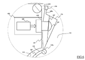
- FIG.6 there is schematically shown an enlarged portion of the laundry machine 100 of FIG.1 with a lighting system according to another embodiment of the present invention.
- the lighting system differs from the above-described lighting systems in what follows.
- a stationary element 602 is provided (in a similar way as above-described, mounted to the frame of the laundry machine 100) with an electric power supply unit 605 coupled to at least one lightning device 610.
- the lightning device 610 may comprise any suitable lighting device, such as an incandescent light lamp, a fluorescent light lamp, a discharge light lamp or a solid-state lighting device ( e.g., a high power LED), or a plurality thereof.
- the light-emitting element 165 advantageously comprises a light-guiding member, such as a prism, a mirror, or a mirrors set, or an optical fiber(s) assembly, adapted to receive light generated by the lighting device 610 and to guide the light towards a different portion of the light-emitting element 165, for example to a free end of the light-emitting element 165 optically connected to a lens 325.
- the light-emitting element 165 is advantageously exposed (without hindering the rotation of the drum 115 in operation) on a backside ( i.e. , the side facing the sidewall 155) of the first flap 140a of the door 135.
- the light-emitting element 165 engages a light-emitting portion of the lightning device 510 exposed on the sidewall 155.
- the light radiation emitted by the lightning device 610 is channeled by the light-emitting element 165 into the drum 115, thus enlightening the inside of the drum 115.
- the lighting device 610 may be arranged in such a way to be able to generate light and to direct it towards the drum 122 also before the opening of the door 135, so as to enlighten the drum 122 (and the door 135) also before its opening, which may be useful in order to help the user to manually rotate the drum 122 for aligning the door 135 with the tub opening 124.
- the light-emitting element may advantageously comprise a plurality of waveguides, each for providing a different orientation of the light radiation towards the inside of the drum (in order to achieve a more complete illumination thereof) and/or for contacting a corresponding plurality of lighting devices in the stationary element.
- light-emitting element may advantageously comprise at least one waveguide split into two portion.
- a first portion may advantageously be connected to the lightning device (in the stationary element) and protruding from the sidewall of the tub opening.
- a second portion may advantageously be exposed on the backside of the first flap of the door.
- the first portion engages the second portion when the drum door is opened, thus channeling the light radiation from the lightning device into the drum as previously described.
- a further embodiment of the present invention may be provided with a light apparatus provided in the second flap of the drum door (preferably, with a corresponding stationary element arranged in a portion of the sidewall where the second flap abuts, or come close to, in the open position), instead of the first flap.
- another embodiment of the present invention may advantageously comprise two lighting apparatuses, one being arranged on the first flap of the drum door, the other being arranged on the second flap of the drum door (each with a respective stationary element near the sidewall). In this way, the inside of the drum may be lit up with a more intense light.
- a drum door with a single flap may be provided.
- a light-emitting element is provided in the single flap of the drum door, preferably protected by a protective cover.
- the coupling between a stationary element and the light-emitting element in the single flap may be obtained either with (in a similar manner as described in relation to FIG.4 , or to FIG.6 ) or without (in a similar manner as described in relation to FIG.3 ) a physical contact between the two.
- a stand-alone power supply unit may be provided in the single flap (in a similar manner as described in relation to FIG.5 ) supplying electric power to the light-emitting element.
- the stationary element may advantageously comprise brush contacts that protrude from a lateral wall of the tub, which are configured for contacting an electrical track provided on the lateral wall of the drum for powering the light-emitting element on the flap of the drum door, when the drum is in the open position.
- the stationary element may advantageously provide electric power to the lightning apparatus by means of a wire, connected to the light-emitting element passing through a rotor shaft provided in the laundry machine connected to the drum and adapted to impart a rotation to the latter in operation (therefore, without the risk of wire tangling during operation).
- the stationary element may advantageously be placed proximal to the rotor shaft.
Landscapes
- Engineering & Computer Science (AREA)
- Textile Engineering (AREA)
- Main Body Construction Of Washing Machines And Laundry Dryers (AREA)
Abstract
Description
- The present invention generally relates to electric appliances. In particular, the present invention is referred to laundry machines, such as top-loading washing machines, washing/drying machines and drying machines, both for domestic and professional use. More particularly, the present invention relates to drum lighting for such laundry machines.
- Each household and professional laundry machine - such as washing machine, washing/drying machines and drying machines - typically comprises, among other components, an inner compartment (including a tub generally housing a rotatable drum) accessible by a user (e.g., through a proper access door and/or lid) for loading/unloading the laundry.
- As known, in laundry machines of the top-loading type, wherein the drum is accessible from the upper side of the laundry machine, the inside of the drum is scarcely enlightened by external environment especially when the user accesses the drum during the loading/unloading of the laundry. Therefore, laundry loading/unloading operations become difficult and uncomfortable for the user.
- In order to solve this drawback, some laundry machines are provided with a lighting apparatus, which substantially comprises one or more light sources - incandescent light lamps, fluorescent light lamps, discharge light lamps or solid-state lighting devices (e.g., high power LEDs) - acting as corresponding light sources for illuminating the drum, and a supply electric assembly - including electronic circuitry, such as rectifiers and controllers, and electrical wires - for generally supplying an operative electric power (from a power source of the machine) to each light source for the energization thereof.
- According to a first known solution, the lighting apparatus may be arranged inside the drum (e.g., in drum walls and/or in lifters inside the drum). Nevertheless, the Applicant has recognized that the approach providing the light source within the drum is intrinsically difficult to implement - substantially due to the fact that the light source, which is arranged on a portion of the machine (i.e., the drum) adapted to rotate with respect to the casing of the machine, has to be electrically connected with the supply electric assembly, which is instead stationary with respect to the casing. Moreover, it may occur that laundry items stored inside the drum cover the light source, thus impeding a functional enlightenment of the drum.
- According to a second known solution, the light source is provided in a frame or hopper provided in correspondence of the loading/unloading opening of the casing and encompassing the tub loading/unloading opening. The Applicant has found that this solution implies several drawbacks, too. For example, properly installing the light source within the frame/hopper is a difficult and time-consuming task. Furthermore, the frame/hopper robustness may be lowered by the insertion of the light source. Moreover, it is difficult to effectively direct the light radiation emitted by the light source towards the inside of the drum.
- The drawbacks of the known solutions are exacerbated by the fact that, in order to meet users requirements, the drum of most of modern machines has increased size for ensuring the required high laundry-capacity, which has repercussions on energy consumption, reliability and complexity aspects of the lighting apparatus.
- The Applicant has handled the problem of devising a satisfactory solution able to provide a satisfactory enlightenment of the inside of the drum, thus facilitating inspection thereof and laundry loading/unloading tasks, at the same time, overcoming the above-discussed drawbacks. Such solution is achieved by providing a light-emitting element in a door for opening/closing the drum, which when the door is opened, emits a light radiation substantially able to thoroughly enlighten the inside of the drum.
- One aspect of the present invention proposes a laundry machine for treating laundry items. The laundry machine comprises an outer casing rotatably housing a drum for accommodating the items to be treated. The drum has a drum opening for accessing the inside of the drum for loading/unloading the items, and a door including at least one door flap that is moveable from a closed position, which closes the drum opening, to an open position, which allows access to the inside of the drum. Furthermore, the laundry machine comprises a lighting system for enlightening the inside of the drum. In the solution according to the present invention, said lighting system comprises a light-emitting element, mounted to the at least one door flap.
- Preferred features of the present invention are set in the dependent claims.
- In an embodiment of the invention, the light-emitting element may comprise at least one lighting device, generating a light radiation.
- In an embodiment of the invention, the lighting system may further comprise a stationary element, stationary with respect to the outer casing, adapted to be coupled with the light-emitting element when at least one door flap is in the open position, said stationary element may supply electric power to said light-emitting element.
- In an embodiment of the invention, the stationary element may be adapted to electrically couple with the light-emitting element without a physical contact.
- In an embodiment of the invention, the stationary element may be adapted to electrically couple with the light-emitting element by means of a physical contact.
- In an embodiment of the invention, the lightning system may comprise a stand-alone power supply unit provided in the at least one flap and coupled with the light-emitting element, said stand-alone power supply unit supplying electric power to said light-emitting element.
- In an embodiment of the invention, the light-emitting element may comprise at least one light-guiding member adapted to transfer light radiation into the inside of the drum, and the lightning system may further comprise a stationary element, stationary with respect to the outer casing, having at least one lightning device adapted to be coupled with the at least one light-guiding member when at least one door flap is in the open position, said at least one lightning device supplying the light radiation to said at least one light-guiding member.
- In an embodiment of the invention, the light-emitting element may be adjustable in orientation in order to allow a user to manually orienting the light radiation emitted by the light-emitting element.
- In an embodiment of the invention, the lighting system may further comprise an optical element coupled to the light-emitting element for optimizing the orientation of the light radiation emitted by said light-emitting element.
- In an embodiment of the invention, the lighting system may further comprise a protective cover for preventing damages to the light-emitting element.
- Another aspect of the present invention provides a method for enlightening the inside of a drum comprised in a laundry machine for treating laundry items. The laundry machine has an outer casing rotatably housing a drum for accommodating the items to be treated, the drum having a drum opening for accessing the inside of the drum for loading/unloading the items, and a door having at least one door flap moveable from a closed position, closing the drum opening, to an open position, allowing access to the inside of the drum. The method comprises the step of enlightening the inside of the drum. In the solution according to the present invention, said step of enlightening comprises enlightening the inside of the drum by means of a light-emitting element, mounted to the at least one door flap.
- In an embodiment of the invention, the method may further comprises the step of supplying electric power to the light-emitting element by means of a stationary element stationary with respect to the outer casing.
- In an embodiment of the invention, the step of supplying electric power to the light-emitting element may further comprise supplying electric power to said light-emitting element only when the at least one door flap is in the open position.
- In an embodiment of the invention, the method may further comprise the step of supplying light radiation to the light-emitting element by means of a stationary element stationary with respect to the outer casing.
- In an embodiment of the invention, the step of supplying light radiation to the light-emitting element may further comprise supplying light radiation to said light-emitting element only when the at least one door flap is in the open position.
- These, and others, features and advantages of the solution according to the present invention will be better understood by reading the following detailed description of some embodiments thereof, provided merely by way of exemplary and non-limitative examples, to be read in conjunction with the attached drawings, wherein:
-
FIG.1 schematically shows a cross-sectional view of a top-loading laundry machine in which an embodiment of the present invention can be applied; -
FIG.2 schematically shows a cross-sectional view of the top-loading washing machine ofFIG.1 with both an appliance lid and a drum door opened; and -
FIG.3 to FIG.6 schematically show cross-sectional views of an enlarged portion of the laundry machine ofFIG.2 , each with a lighting system according to a different embodiment of the present invention. - Considering
FIG.1 andFIG.2 together, wherein cross-sectional views of alaundry machine 100, in which an embodiment of the present invention can be applied, are schematically shown. - The
laundry machine 100 is a machine for treating laundry (such has a laundry washing machine, a laundry washing/drying machine, a laundry drying machine etc.) of the top-loading type. - The
laundry machine 100 comprises a substantially parallelepiped-shaped casing 105 that, preferably, although not necessarily, encloses a substantially cylindrical-shaped tub 110, wherein the laundry is washed, along with any other component of thelaundry machine 100 necessary for the operation (e.g., hydraulic, electronic and electromechanical apparatuses well known in the art and, therefore, not shown in the figures nor herein described for sake of conciseness). - In detail, the
tub 110 is preferably fixed to a frame (which substantially supports thecasing 105 and any other component comprised in the laundry machine, and not shown in the figures), preferably by supporting elastic coils (not illustrated), and shock (and vibration) absorber elements, such as two shock absorbers 112 (which absorb jolts of the tub during operation). - Furthermore, the
tub 110 houses a substantially cylindrical-shaped rotatingdrum 115, which, in operation, rotates about an axis A in order to tumble the laundry to be washed. Preferably, although not necessarily, baffles or lifters 120 (three shown in the figures) are mounted on a drum wall 122 (parallel to a drum rotation axis A) in the inside of thedrum 115 for enhancing the tumbling action performed in operation by the same. - In order to allow a user to access the
tub 110, anopening 124 is advantageously provided on the top of thewashing machine 100. The opening 124 is closable by alid 125, which is preferably, although not necessarily, hingeably connected to thecasing 105 by means of ahinge 130. Thelid 125 is able to pivot from a closed position (shown inFIG.1 ) - wherein thelid 125 closes theopening 124, impeding the access to the tub 110-to an open position (shown inFIG.2 ) - wherein thelid 125 is pivoted to an angle, preferably, equal to, or greater than, 90° with respect to the closed position, allowing the access to thetub 110. - Similarly, in order to allow a user to access the inside of the drum 115 (for loading/unloading the laundry), a drum opening is provided in the
drum wall 122 and adoor 135 is provided for closing the same during operation. Preferably, although not limitatively, thedoor 135 comprises afirst flap 140a and asecond flap 140b. In detail, thefirst flap 140a is hinged to thedrum 115 by afirst flap hinge 145a, while thesecond flap 140b is hinged to thedrum 115 by asecond flap hinge 145b. In a closed position (shown inFIG.1 ),interlocking elements 150 block the first and thesecond flaps door 135 during operation (i.e., when the drum rotates). Clearly, in a further embodiment, not illustrated,door 135 may comprise a single flap; the following description refers to a door comprising two flaps, but it can as well be applied to a door comprising a single flap (for example when, in the following, reference is made to the "first flap 140a", it can be read also as "single flap" in case thedoor 135 comprises only a single flap). - In order to have the
door 135 in an open position (shown inFIG.2 ), thelaundry machine 100, at the end of the operation, preferably aligns thedoor 135 with the opening 124 - alternatively or in addition, the user may align thedoor 135 with the opening 124 manually -; then theinterlocking elements 150 have to be unlocked; lastly, the user has to pivot both the first andsecond flaps lateral sidewalls 155 of the opening 124. - Having the
machine lid 125 and thedrum door 135 both in the open position, the inside of thedrum 115 is accessible (through the drum opening) by the user for loading/unloading the laundry stored therein. - In addition, preferably, although not limitatively, a
user interface 160, for the selection of laundry treatment parameters (e.g., a temperature of a treatment fluid, a maximum rotation speed of thedrum 115, etc.), is provided on the top of thecasing 105. - In the laundry machine according to the present invention, a lighting system is provided for enlightening the inside of the drum (preferably, when the drum door is in the open position).
- Advantageously in the solution according to the present invention, the lighting system comprises a light-emitting element provided on at least one flap of the door of the drum, for lighting the inside of the drum, when the door of the drum is in the open position. The light-emitting element is stationary with respect to the door of the drum, thus the former rotates - with respect to the casing - together with the latter during the operation of the
laundry machine 100. - In the example at issue, a light-emitting element 165 - depicted with a dashed line in the figures - is provided on the
first flap 140a of thedoor 135 and preferably, although not limitatively, is protected by a protective cover 170 (as will described in greater detail in the following). Advantageously, the light-emittingelement 165 may be activated (i.e., to emit a light radiation) when thedoor 135 is in the open position, with thefirst flap 140a that abuts, or comes close to (i.e., at a minimum distance), a portion of thesidewall 155. - The light-emitting
element 165 may comprise any suitable lighting device, such as an incandescent light lamp, a fluorescent light lamp, a discharge light lamp or a solid-state lighting device (e.g., a LED - Light-Emitting Diode). It should be noted that the light-emittingelement 165 might comprise more than just one of the lighting devices listed above (e.g., the light-emittingelement 165 may comprise a plurality of LEDs in a strip or a ring arrangement) in order to obtain a desired illumination intensity (i.e., able to grant a satisfactory enlightenment of the drum 115). - It is underlined that in present application expression "light-emitting element" has not to be interpreted only as a lamp or a similar "light-generating" device, but it refer to any device adapted to emit light, for example the edge of an optical fiber, or of a lightguide (for example the free edge of a cylinder made of transparent plastics or glass).
- In some embodiments according to the present invention, the lightning system may comprise a stationary element fixed to the frame of the laundry machine. Therefore, such stationary element results, preferably, stationary with respect to the casing of the laundry machine. For example, in some embodiments of the invention, the stationary element is adapted to supply an electric power to the light-emitting element (as will be described in greater detail in the following).
- Turning now to
FIG.3 , there is schematically shown a cross-sectional view of an enlarged portion of thelaundry machine 100 ofFIG.2 according to an embodiment of the present invention. - According to this embodiment, a
stationary element 302 is adapted to supply electric power to the light-emittingelement 165, with the latter that may, advantageously, be coupled with the former (as will be discussed below) when thedrum door 135 is in the open position. Preferably, although not necessarily, the stationary element is positioned (fixed to the frame of the laundry machine 100) substantially behind the portion of thesidewall 115 to which thefirst flap 140a abuts, or comes close. - The
stationary element 302 and the light-emittingelement 165 may be coupled to one another by means of a contact-less (or wireless) coupling. Thestationary element 302 may advantageously comprise apower supply unit 305. For example, thepower supply unit 305 receives electric power from a power source, such as the mains (not shown in the figures), a power circuit (not shown in the figures) of thelaundry machine 100 or a battery arrangement (which may be provided within thestationary element 302, not shown) and, in its turns, provides suitable (AC) voltages and currents to atransmission circuit 310. Thetransmission circuit 310 is adapted to transfer electric power by means of an electromagnetic wave (for example, by comprising a radio-frequency transmitter or a wire winding) to the light-emittingelement 165. Clearly thepower supply unit 305 and thetransmission circuit 310 may be advantageously integrated in a single electronic component. - Advantageously, the lighting system may comprise a receiver circuit 315 (which comprises a radio-frequency receiver or a corresponding coupled wire winding) provided in the
first door flap 140a and electrically connected to the light-emittingelement 165. Preferably, although not necessarily, the lighting system also comprises an optical element, such as alens 325 coupled to the light-emittingelement 165 in order to optimize the orientation of the light radiation emitted by the same. Theprotective cover 170 may advantageously be provided in the lighting system for preventing damages to the light-emittingelement 165 and to the lens 325 (i.e., elements of the lighting system exposed inside the drum). - When the
flap 140a abuts, or comes close to (i.e., at a minimum distance), the sidewall 155 (i.e., when thelid 125 and thedoor 135 are in the open position), thetransmission circuit 310 transfers electric power (by means of the electromagnetic wave) to thereceiver circuit 315, which is adapted to properly provide such received electric power (i.e., as suitable voltages and currents) to the light-emittingelement 165 connected to the same. - Preferably, although not necessarily, the
receiver circuit 315 and the light-emittingelement 165 are mounted in an hermetically-sealed portion of thefirst door flap 140a, in order to protect them from liquid and/or moisture present in thetub 110 during thelaundry machine 100 operation. - The
lens 325 is, preferably, coupled with the light-emittingelement 165 in order to optimize the orientation of the light radiation emitted by the same inside thedrum 115. In this way, the inside of thedrum 115 is thoroughly well lit, thus allowing easier loading/unloading operations. Thelens 325 is made, preferably, of a durable and temperature-resistant transparent material, such as borosilicate glass (e.g., Pyrex ®) or polymethyl methacrylate (e.g., Plexiglas ®). - Alternatively, the
lens 325 may be omitted and the light-emitting portion of the light-emittingelement 165 may be, at least partly, directly exposed towards the inside of thedrum 115. - The
protective cover 170 is adapted to prevent damages to thelens 325, the light-emittingelement 165 and thereceiver circuit 315, especially during the operation of thelaundry machine 100. Theprotective cover 170 may also provide preliminary orientation to the light radiation emitted by the light-emittingelement 165; for example, theprotective cover 170 may be formed in such a way to shield the user from being directly hit by the light radiation emitted by the light-emittingelement 165, thus preventing glare and dazzling effects. Theprotective cover 170 may be made of any suitable material for the use in the drum 115 (such as metal or plastic) and may be formed integral with thefirst flap 140a. - In addition, an internal portion of the
protective cover 170 could be treated in order to reflect the light emitted by the light-emittingelement 165, thus achieving a better concentration of the light radiation toward the inside of thedrum 115. For example, the internal portion of theprotective cover 170 could be polished (if made of metal) or covered with a light reflecting coating (e.g., enamel painting). - In further embodiments according to the present invention, the light-emitting element 165 (and/or the lens 325) may advantageously be made adjustable in orientation in such a way to allow the user to manually adjust an orientation of the light radiation emitted by the same according to her/his needs. For example, the light-emitting
element 165 may advantageously be telescopic or comprise telescopic portions, in order to be extendable towards the inside of thedrum 115 to a predetermined extension; alternatively or in addition, the light-emittingelement 165 could be made rotatable about a predetermined rotation axis. - With the embodiment according to the present invention just described, it is possible to effectively enlighten the inside of the drum of the laundry machine; moreover it is possible to supply electric power to the light-emitting element in a relatively simple manner which is substantially free from safety issues (since there is no coupling during the laundry machine operation and until the user pivots the door flap in the open position).
- Considering now
FIG.4 , there is schematically shown a cross-sectional view of an enlarged portion of thelaundry machine 100 ofFIG.2 with a lightning system according to another embodiment of the present invention. - In detail, the embodiment depicted in the figure differs from the one described in
FIG.3 substantially in the fact that electric power is transferred from astationary element 402 to the light-emittingsource 165 through a physical contact (i.e., a wired electrical connection). - Preferably, the
stationary element 402 comprises anelectric power source 405, which provides voltages and currents to a transmission circuit 410 (clearly theelectric power source 405 and thetransmission circuit 410 may be advantageously integrated in a single electronic component). For example, thepower supply unit 405 receives electric power from a power source, such as the mains (not shown in the figures), a power circuit (not shown in the figures) of thelaundry machine 100 or a battery arrangement (which may be provided within thestationary element 402, not shown). According to this embodiment, thetransmission circuit 410 advantageously comprisesfirst contact elements 415a (e.g., pins, needles, etc.; two shown in the figure) that are advantageously adapted to engage correspondingsecond contact elements 415b (e.g., pads for the pins, slots for the needles, etc.; two shown in the figure). For example, thefirst contact elements 415a, preferably, protrude from thesidewall 155 in theopening 124, while thesecond contact elements 415b are, preferably, provided on a backside (i.e., the side facing the sidewall 155) of thefirst flap 140a of thedoor 135. - The coupling between the
transmission circuit 410 and a receiver circuit 420 (provided in thefirst flap 140a of the drum 115), is then provided through the physical contact formed by the reciprocal engagement of the first andsecond contact elements door 135 is in the open position (with thefirst flap 140a abutting, or close to, the side wall 155). - Therefore, the
receiver circuit 420 receives the electric power from thetransmission circuit 410 and provides the same to the light-emittingelement 165 thanks to thecontact elements FIG.3 . - Turning now to
FIG.5 , there is schematically shown an enlarged portion of thelaundry machine 100 ofFIG.1 with a lighting system according to another embodiment of the present invention. - Advantageously, a stand-alone
power supply unit 505 may be directly provided in thefirst flap 140a. For example, the stand-alonepower supply unit 505 may comprise abattery arrangement 505a and a voltage/current regulator 505b coupled one another. - Preferably, the voltage/
current regulator 505b is also coupled with the light-emittingelement 165 and is adapted to properly provide working current and voltage to the same. The stand-alonepower supply unit 505 is thus stationary with thedoor 135 of the drum 115 (i.e., it rotates together with thedrum 115 in operation). - Preferably, the stand-alone
power supply unit 505 is mounted in a hermetically sealed portion of thefirst door flap 140a together with the light-emittingelement 165. - Having the stand-alone
power supply unit 505 housed within thefirst flap 140a, allows achieving a more compact lightning system, removing the need for a stationary element fixed to the frame of thelaundry machine 100. - Turning now to
FIG.6 , there is schematically shown an enlarged portion of thelaundry machine 100 ofFIG.1 with a lighting system according to another embodiment of the present invention. - The lighting system differs from the above-described lighting systems in what follows.
- Advantageously, a
stationary element 602 is provided (in a similar way as above-described, mounted to the frame of the laundry machine 100) with an electricpower supply unit 605 coupled to at least onelightning device 610. Thelightning device 610 may comprise any suitable lighting device, such as an incandescent light lamp, a fluorescent light lamp, a discharge light lamp or a solid-state lighting device (e.g., a high power LED), or a plurality thereof. - According to this embodiment, the light-emitting
element 165 advantageously comprises a light-guiding member, such as a prism, a mirror, or a mirrors set, or an optical fiber(s) assembly, adapted to receive light generated by thelighting device 610 and to guide the light towards a different portion of the light-emittingelement 165, for example to a free end of the light-emittingelement 165 optically connected to alens 325. Preferably, the light-emittingelement 165 is advantageously exposed (without hindering the rotation of thedrum 115 in operation) on a backside (i.e., the side facing the sidewall 155) of thefirst flap 140a of thedoor 135. In this way, when thedoor 135 is in the open position (with thefirst flap 140a abutting, or close to, the side wall 155), the light-emittingelement 165 engages a light-emitting portion of the lightning device 510 exposed on thesidewall 155. Advantageously, in such a configuration of the lightning system, the light radiation emitted by thelightning device 610 is channeled by the light-emittingelement 165 into thedrum 115, thus enlightening the inside of thedrum 115. - It should be noted that, in the just described embodiment of the present invention, no electric or electronic element are necessary in the door flap. Thus, the resulting lightning apparatus has an improved robustness against moisture and liquid contact than other solutions, since its electric and electronic elements can be fully isolated from liquid and/or moisture.
- Moreover in this embodiment the
lighting device 610 may be arranged in such a way to be able to generate light and to direct it towards thedrum 122 also before the opening of thedoor 135, so as to enlighten the drum 122 (and the door 135) also before its opening, which may be useful in order to help the user to manually rotate thedrum 122 for aligning thedoor 135 with thetub opening 124. - Alternatively, the light-emitting element may advantageously comprise a plurality of waveguides, each for providing a different orientation of the light radiation towards the inside of the drum (in order to achieve a more complete illumination thereof) and/or for contacting a corresponding plurality of lighting devices in the stationary element.
- As a further alternative, light-emitting element may advantageously comprise at least one waveguide split into two portion. A first portion may advantageously be connected to the lightning device (in the stationary element) and protruding from the sidewall of the tub opening. A second portion may advantageously be exposed on the backside of the first flap of the door. Advantageously, the first portion engages the second portion when the drum door is opened, thus channeling the light radiation from the lightning device into the drum as previously described.
- A further embodiment of the present invention (not shown in the figures) may be provided with a light apparatus provided in the second flap of the drum door (preferably, with a corresponding stationary element arranged in a portion of the sidewall where the second flap abuts, or come close to, in the open position), instead of the first flap. In addition, another embodiment of the present invention may advantageously comprise two lighting apparatuses, one being arranged on the first flap of the drum door, the other being arranged on the second flap of the drum door (each with a respective stationary element near the sidewall). In this way, the inside of the drum may be lit up with a more intense light.
- Conversely, in a further embodiment according to the present invention, a drum door with a single flap may be provided. In this case, a light-emitting element is provided in the single flap of the drum door, preferably protected by a protective cover. The coupling between a stationary element and the light-emitting element in the single flap may be obtained either with (in a similar manner as described in relation to
FIG.4 , or toFIG.6 ) or without (in a similar manner as described in relation toFIG.3 ) a physical contact between the two. Alternatively, a stand-alone power supply unit may be provided in the single flap (in a similar manner as described in relation toFIG.5 ) supplying electric power to the light-emitting element. - According to an even further embodiment of the present invention (not shown in the figures) the stationary element may advantageously comprise brush contacts that protrude from a lateral wall of the tub, which are configured for contacting an electrical track provided on the lateral wall of the drum for powering the light-emitting element on the flap of the drum door, when the drum is in the open position.
- According to another embodiment of the present invention (not shown in the figures), the stationary element may advantageously provide electric power to the lightning apparatus by means of a wire, connected to the light-emitting element passing through a rotor shaft provided in the laundry machine connected to the drum and adapted to impart a rotation to the latter in operation (therefore, without the risk of wire tangling during operation). In such embodiment, the stationary element may advantageously be placed proximal to the rotor shaft.
Claims (15)
- A laundry machine (100) for treating laundry items comprising:an outer casing (105) rotatably housing a drum (115) for accommodating the items to be treated, the drum (115) having a drum opening for accessing the inside of the drum (115) for loading/unloading the items, and a door (135) including at least one door flap (140a, 140b) moveable from a closed position, closing the drum opening, to an open position, allowing access to the inside of the drum, anda lighting system (165,302; 165,402; 165,505; 165,602) for enlightening the inside of the drum (115),
characterized in that
said lighting system (165,302; 165,402; 165,505; 165,602) comprises a light-emitting element (165), mounted to the at least one door flap (140a). - The laundry machine (100) according to claim 1, wherein the light-emitting element comprises at least one lighting device, generating a light radiation.
- The laundry machine (100) according to claim 2, wherein the lighting system further comprises a stationary element (302; 402), stationary with respect to the outer casing (105), adapted to be coupled with the light-emitting element (165) when at least one door flap (140a) is in the open position, said stationary element (302; 402) supplying electric power to said light-emitting element (165).
- The laundry machine (100) according to claim 3, wherein the stationary element (302) is adapted to electrically couple with the light-emitting-element (165) without (310,315) a physical contact.
- The laundry machine (100) according to claim 3, wherein the stationary element (402) is adapted to electrically couple with the light-emitting element (165) by means of a physical contact (415a,415b).
- The laundry machine (100) according to claim 2, wherein the lightning system comprises a stand-alone power supply unit (505) provided in the at least one flap (140a, 140b) and coupled with the light-emitting element (165), said stand-alone power supply unit (505) supplying electric power to said light-emitting element (165).
- The laundry machine (100) according to claim 1, wherein the light-emitting element (165) comprises at least one light-guiding member (165) adapted to transfer light radiation into the inside of the drum (115), and
wherein the lightning system further comprises a stationary element (602), stationary with respect to the outer casing (105), having at least one lightning device (610) adapted to be coupled with the at least one light-guiding member (165) when at least one door flap (140a) is in the open position, said at least one lightning device (610) supplying the light radiation to said at least one light-guiding member (165). - The laundry machine (100) according to any of the preceding claims, wherein the light-emitting element (165) is adjustable in orientation in order to allow a user to manually orienting the light radiation emitted by the light-emitting element (165).
- The laundry machine (100) according to any one among the preceding claims, wherein the lighting system (165,302; 165,402; 165,505; 165,602) further comprises an optical element (325) coupled to the light-emitting element (165) for optimizing the orientation of the light radiation emitted by said light-emitting element (165).
- The laundry machine (100) according to any one among the preceding claims, wherein the lighting system (165,302; 165,402; 165,505; 165,602) further comprises a protective cover (170) for preventing damages to the light-emitting element (165).
- A method for enlightening the inside of a drum (115) comprised in a laundry machine (100) for treating laundry items having an outer casing (105) rotatably housing a drum (115) for accommodating the items to be treated, the drum having a drum opening for accessing the inside of the drum (115) for loading/unloading the items, and a door (135) including at least one door flap (140a) moveable from a closed position, closing the drum opening, to an open position, allowing access to the inside of the drum, the method comprising the step of
enlightening the inside of the drum (115),
characterized in that said step of enlightening comprises:
enlightening the inside of the drum by means of a light-emitting element (165), mounted to the at least one door flap (140a). - The method according to claim 11, further comprising the step of:supplying electric power to the light-emitting element (165) by means of a stationary element (302; 402) stationary with respect to the outer casing (105).
- The method according to claim 12, wherein the step of supplying electric power to the light-emitting element (165) further comprises:supplying electric power to said light-emitting element (165) only when the at least one door flap (140a) is in the open position.
- The method according to claim 11, further comprising the step of:supplying light radiation to the light-emitting element (165) by means of a stationary element (602) stationary with respect to the outer casing (105).
- The method according to claim 14, wherein the step of supplying light radiation to the light-emitting element (165) further comprises:supplying light radiation to said light-emitting element (165) only when the at least one door flap (140a) is in the open position.
Priority Applications (1)
| Application Number | Priority Date | Filing Date | Title |
|---|---|---|---|
| EP11193995.5A EP2604734A1 (en) | 2011-12-16 | 2011-12-16 | Lighting apparatus for laundry machines |
Applications Claiming Priority (1)
| Application Number | Priority Date | Filing Date | Title |
|---|---|---|---|
| EP11193995.5A EP2604734A1 (en) | 2011-12-16 | 2011-12-16 | Lighting apparatus for laundry machines |
Publications (1)
| Publication Number | Publication Date |
|---|---|
| EP2604734A1 true EP2604734A1 (en) | 2013-06-19 |
Family
ID=45440209
Family Applications (1)
| Application Number | Title | Priority Date | Filing Date |
|---|---|---|---|
| EP11193995.5A Withdrawn EP2604734A1 (en) | 2011-12-16 | 2011-12-16 | Lighting apparatus for laundry machines |
Country Status (1)
| Country | Link |
|---|---|
| EP (1) | EP2604734A1 (en) |
Cited By (4)
| Publication number | Priority date | Publication date | Assignee | Title |
|---|---|---|---|---|
| EP3231930A1 (en) * | 2016-04-15 | 2017-10-18 | Miele & Cie. KG | Door locking device for a household appliance and household appliance |
| CN110195316A (en) * | 2018-02-26 | 2019-09-03 | 青岛海尔洗衣机有限公司 | Top-opening type clothes treatment device and its inside drum cover operating system |
| CN111850927A (en) * | 2019-04-30 | 2020-10-30 | 青岛海尔滚筒洗衣机有限公司 | A drum washing machine |
| US20220167825A1 (en) * | 2020-12-01 | 2022-06-02 | Haier Us Appliance Solutions, Inc. | Dishwashing appliance having a wirelessly powered light assembly |
Citations (4)
| Publication number | Priority date | Publication date | Assignee | Title |
|---|---|---|---|---|
| DE19649039C1 (en) * | 1996-11-27 | 1998-04-30 | Bauknecht Hausgeraete | Washing machine, giving effective illumination |
| US5870787A (en) * | 1995-11-09 | 1999-02-16 | Samsung Electronics Co., Ltd. | Door driving control apparatus and method for a washing machine |
| DE102004015081A1 (en) * | 2004-03-25 | 2005-10-20 | Miele & Cie | Illumination device for washing machine has light arrangement arranged inside door in holder for mounting ring for door's viewing glass so as to at least approximately enclose viewing glass |
| US20100132415A1 (en) * | 2006-10-31 | 2010-06-03 | Erman Cevikkalp | washer/dryer |
-
2011
- 2011-12-16 EP EP11193995.5A patent/EP2604734A1/en not_active Withdrawn
Patent Citations (4)
| Publication number | Priority date | Publication date | Assignee | Title |
|---|---|---|---|---|
| US5870787A (en) * | 1995-11-09 | 1999-02-16 | Samsung Electronics Co., Ltd. | Door driving control apparatus and method for a washing machine |
| DE19649039C1 (en) * | 1996-11-27 | 1998-04-30 | Bauknecht Hausgeraete | Washing machine, giving effective illumination |
| DE102004015081A1 (en) * | 2004-03-25 | 2005-10-20 | Miele & Cie | Illumination device for washing machine has light arrangement arranged inside door in holder for mounting ring for door's viewing glass so as to at least approximately enclose viewing glass |
| US20100132415A1 (en) * | 2006-10-31 | 2010-06-03 | Erman Cevikkalp | washer/dryer |
Cited By (5)
| Publication number | Priority date | Publication date | Assignee | Title |
|---|---|---|---|---|
| EP3231930A1 (en) * | 2016-04-15 | 2017-10-18 | Miele & Cie. KG | Door locking device for a household appliance and household appliance |
| CN110195316A (en) * | 2018-02-26 | 2019-09-03 | 青岛海尔洗衣机有限公司 | Top-opening type clothes treatment device and its inside drum cover operating system |
| CN110195316B (en) * | 2018-02-26 | 2021-07-06 | 重庆海尔洗衣机有限公司 | Top-opening laundry processing equipment and its inner cylinder cover operating system |
| CN111850927A (en) * | 2019-04-30 | 2020-10-30 | 青岛海尔滚筒洗衣机有限公司 | A drum washing machine |
| US20220167825A1 (en) * | 2020-12-01 | 2022-06-02 | Haier Us Appliance Solutions, Inc. | Dishwashing appliance having a wirelessly powered light assembly |
Similar Documents
| Publication | Publication Date | Title |
|---|---|---|
| US9150995B2 (en) | Laundry machine with lighting apparatus for drum lighting | |
| CN210420584U (en) | laundry treatment equipment | |
| WO2008052659A1 (en) | Washing machine with a wash drum lighting device | |
| ES2348908T3 (en) | CLOTHING TREATMENT MACHINE WITH A LIGHTING DEVICE. | |
| CN101397742A (en) | Drum-type washer | |
| BR112014030497B1 (en) | Balancer arranged to be mounted on a rotating drum to compensate for an unbalanced load generated in rotation of the rotating drum, and washing machine | |
| EP2302125A1 (en) | Washing machine with improved heating system | |
| EP2604741B1 (en) | Lighting apparatus for laundry machines | |
| RU2685880C2 (en) | Household appliance, having light source | |
| KR20180136140A (en) | Wall mounted drum type washing machine | |
| RU2009120514A (en) | WASHING AND DRYING MACHINE | |
| CN107780150A (en) | Transparent display screen and device for clothing processing for device for clothing processing | |
| US20140061188A1 (en) | Lighting assembly for microwave oven illumination and microwave oven equipped with the same | |
| MX2014014796A (en) | Balancing module and washing machine having the same. | |
| DE102004015081A1 (en) | Illumination device for washing machine has light arrangement arranged inside door in holder for mounting ring for door's viewing glass so as to at least approximately enclose viewing glass | |
| KR20150003596U (en) | Body sensors and electronic timer built-in rechargeable UV disinfection unit | |
| CN112064297B (en) | Clothes processing equipment | |
| CN114616372A (en) | Front loading washing machine with electric lamp body | |
| CN223840284U (en) | Lighting device | |
| CN210249504U (en) | Electric rice cooker | |
| CN111979686B (en) | Clothes treating apparatus | |
| KR20170105201A (en) | Washing machine | |
| KR20170137289A (en) | The lighting device of the kitchen furniture | |
| CN119934469A (en) | A lighting device | |
| KR100198577B1 (en) | Main unit power supply of induction cooker |
Legal Events
| Date | Code | Title | Description |
|---|---|---|---|
| PUAI | Public reference made under article 153(3) epc to a published international application that has entered the european phase |
Free format text: ORIGINAL CODE: 0009012 |
|
| AK | Designated contracting states |
Kind code of ref document: A1 Designated state(s): AL AT BE BG CH CY CZ DE DK EE ES FI FR GB GR HR HU IE IS IT LI LT LU LV MC MK MT NL NO PL PT RO RS SE SI SK SM TR |
|
| AX | Request for extension of the european patent |
Extension state: BA ME |
|
| 17P | Request for examination filed |
Effective date: 20131216 |
|
| RBV | Designated contracting states (corrected) |
Designated state(s): AL AT BE BG CH CY CZ DE DK EE ES FI FR GB GR HR HU IE IS IT LI LT LU LV MC MK MT NL NO PL PT RO RS SE SI SK SM TR |
|
| STAA | Information on the status of an ep patent application or granted ep patent |
Free format text: STATUS: THE APPLICATION IS DEEMED TO BE WITHDRAWN |
|
| 18D | Application deemed to be withdrawn |
Effective date: 20180703 |