EP2604512A2 - Dichtung für verschiebbare Kabeleinrichtung - Google Patents
Dichtung für verschiebbare Kabeleinrichtung Download PDFInfo
- Publication number
- EP2604512A2 EP2604512A2 EP12195396.2A EP12195396A EP2604512A2 EP 2604512 A2 EP2604512 A2 EP 2604512A2 EP 12195396 A EP12195396 A EP 12195396A EP 2604512 A2 EP2604512 A2 EP 2604512A2
- Authority
- EP
- European Patent Office
- Prior art keywords
- seal
- slat
- strut
- aperture
- assembly according
- Prior art date
- Legal status (The legal status is an assumption and is not a legal conclusion. Google has not performed a legal analysis and makes no representation as to the accuracy of the status listed.)
- Granted
Links
Images




Classifications
-
- B—PERFORMING OPERATIONS; TRANSPORTING
- B64—AIRCRAFT; AVIATION; COSMONAUTICS
- B64C—AEROPLANES; HELICOPTERS
- B64C9/00—Adjustable control surfaces or members, e.g. rudders
- B64C9/14—Adjustable control surfaces or members, e.g. rudders forming slots
- B64C9/22—Adjustable control surfaces or members, e.g. rudders forming slots at the front of the wing
-
- B—PERFORMING OPERATIONS; TRANSPORTING
- B64—AIRCRAFT; AVIATION; COSMONAUTICS
- B64C—AEROPLANES; HELICOPTERS
- B64C9/00—Adjustable control surfaces or members, e.g. rudders
- B64C9/02—Mounting or supporting thereof
-
- B—PERFORMING OPERATIONS; TRANSPORTING
- B64—AIRCRAFT; AVIATION; COSMONAUTICS
- B64D—EQUIPMENT FOR FITTING IN OR TO AIRCRAFT; FLIGHT SUITS; PARACHUTES; ARRANGEMENT OR MOUNTING OF POWER PLANTS OR PROPULSION TRANSMISSIONS IN AIRCRAFT
- B64D15/00—De-icing or preventing icing on exterior surfaces of aircraft
- B64D15/12—De-icing or preventing icing on exterior surfaces of aircraft by electric heating
-
- Y—GENERAL TAGGING OF NEW TECHNOLOGICAL DEVELOPMENTS; GENERAL TAGGING OF CROSS-SECTIONAL TECHNOLOGIES SPANNING OVER SEVERAL SECTIONS OF THE IPC; TECHNICAL SUBJECTS COVERED BY FORMER USPC CROSS-REFERENCE ART COLLECTIONS [XRACs] AND DIGESTS
- Y02—TECHNOLOGIES OR APPLICATIONS FOR MITIGATION OR ADAPTATION AGAINST CLIMATE CHANGE
- Y02T—CLIMATE CHANGE MITIGATION TECHNOLOGIES RELATED TO TRANSPORTATION
- Y02T50/00—Aeronautics or air transport
- Y02T50/30—Wing lift efficiency
-
- Y—GENERAL TAGGING OF NEW TECHNOLOGICAL DEVELOPMENTS; GENERAL TAGGING OF CROSS-SECTIONAL TECHNOLOGIES SPANNING OVER SEVERAL SECTIONS OF THE IPC; TECHNICAL SUBJECTS COVERED BY FORMER USPC CROSS-REFERENCE ART COLLECTIONS [XRACs] AND DIGESTS
- Y02—TECHNOLOGIES OR APPLICATIONS FOR MITIGATION OR ADAPTATION AGAINST CLIMATE CHANGE
- Y02T—CLIMATE CHANGE MITIGATION TECHNOLOGIES RELATED TO TRANSPORTATION
- Y02T50/00—Aeronautics or air transport
- Y02T50/40—Weight reduction
Definitions
- the present invention relates to an aircraft wing assembly having a leading edge slat, and in particular to a translating cable device for electrically connecting the slat to the wing.
- Ice protection of aircraft leading edge structures has traditionally been provided on larger commercial fixed wing aircraft through the use of bleed air. More recently, there has been a move to incorporate electrical de-icing systems because of their greater efficiency.
- the areas of commercial fixed wing aircraft that have particular need for ice protection are the movable leading edge slat structures.
- WO2006/027624A describes a coupling arrangement for coupling services between an aircraft wing fixed aerofoil component and a extendable leading edge slat mounted thereto.
- the coupling arrangement includes a housing for connection to the fixed aerofoil structure, and a hollow telescopic assembly extendable between a retracted and an extended position.
- a service carrying conduit arrangement carries the services, such as electrical power cables, between the fixed aerofoil component and the leading edge slat, and extends through the hollow telescopic assembly.
- the service carrying conduit arrangement is flexible and excess thereof is located within the housing when the telescopic assembly is in the retracted position.
- the telescopic assembly is coupled at one end to the slat, and therefore translates with respect to the fixed aerofoil component as the slat moves.
- the fixed aerofoil component has an aperture to accommodate the telescopic assembly.
- the aperture is elongate to permit rotation of the telescopic assembly in a vertical plane as the slat moves.
- the aperture in the fixed leading edge structure is covered by the slat when the slat is retracted but faces the oncoming airflow when the slat is deployed for the high-lift (take-off and landing) configurations.
- the aperture causes aerodynamic drag and undesirable flow disturbances over the wing in the high-lift configurations.
- the invention provides an aircraft wing assembly, comprising a wing having a fixed leading edge, a slat mounted for movement between a retracted position and an extended position with respect to the fixed leading edge, and a translating cable device for electrically connecting the slat to the wing and having a strut coupled at one end to the slat, the fixed leading edge having an aperture to accommodate the strut, and a seal assembly for sealing between the strut and the aperture.
- the seal assembly may include a first seal fixed adjacent the aperture, and a second seal fixed to the strut of the translating cable device.
- the first and second seals preferably cooperate when the slat is moved to one or more predetermined positions.
- a plurality of second seals may be provided, each cooperating with the first seal at a respective different slat position.
- the translating cable device may have a proximal end mounted to the wing and a distal end coupled to the slat.
- the seal assembly may include a flap seal (a first seal) mounted to the fixed leading edge and projecting into the aperture.
- the flap seal may include a plurality of flap seal sections with a gap between adjacent sections.
- the flap seal may be mounted to a portion of the fixed leading edge substantially surrounding the aperture.
- the flap seal may include a first portion mounted to an interior surface of a panel defining the fixed leading edge adjacent an edge of the aperture, and a second portion within the aperture and substantially conformal with an outer surface of the panel.
- the flap seal may have a central cut-out.
- the translating cable device may include either an articulating mechanism (such as described in WO2009/130473A ), or a telescoping mechanism (such as described in US2010/0327111A ).
- the articulating mechanism may include a first strut pivotally mounted to the wing, and a second strut having a proximal end pivotally connected to the first strut and a distal end coupled to the slat.
- the second strut may be curved.
- the seal assembly may include a plug seal (a second seal) fixed to the strut at a location remote from the end of the strut which is coupled to the slat.
- the plug seal may be arranged to enter the aperture in the fixed leading edge when the slat is fully extended, and to withdraw from the aperture into the wing when the slat is retracted.
- the seal assembly may include a seal boot (a second seal) covering the coupling between the translating cable device and the slat.
- a seal boot (a second seal) covering the coupling between the translating cable device and the slat.
- the seal boot may act as a protective covering to prevent damage to the first seal from protruding elements, such as bolts, for example, of the coupling as it moves through the aperture.
- the translating cable device may be passively driven by movement of the slat.
- the aircraft wing assembly may further comprise a slat actuation mechanism for driving the slat between its extended and retracted positions.
- Figure 1 illustrates a fixed wing commercial aircraft of conventional type having a fuselage 1, wings 2, under-wing mounted engines 3, and horizontal and vertical stabiliser surfaces 4, 5 respectively.
- this invention is not limited to a particular type of aircraft, or aircraft configuration, except insofar as the wings 2 have movable leading edge slats 6.
- this invention is applicable to a wide variety of commercial and military aircraft, having a variety of different power plants (e.g. jet, turbo-prop, etc.) mounted in a variety of locations (e.g. fuselage, tail, over-wing, under-wing), wing configurations (e.g. high wing, low wing, blended wing body, etc.), wing planforms (e.g. forward swept, unswept, aft swept, etc.), and a variety of stabiliser surfaces including tail planes, canards etc.
- power plants e.g. jet, turbo-prop, etc.
- locations e.g. fuselage, tail, over-wing, under-wing
- wing configurations e.g. high wing, low wing, blended wing body, etc.
- wing planforms e.g. forward swept, unswept, aft swept, etc.
- stabiliser surfaces including tail planes, canards etc.
- Figure 2 illustrates a partially cut-away view of the wing leading edge region showing the wing 2 having a fixed leading edge 7 and one of the slats 6 fully retracted and stowed against the fixed leading edge 7.
- the slat is movable between a retracted position and a plurality of extended positions (including a take off position, and a landing position) by a slat actuation mechanism.
- the slat actuation mechanism includes a slat track 8 of conventional type. A detailed discussion of the slat track and other components of the slat actuation mechanism will therefore not be repeated here.
- the slat may be moved by a variety of different slat actuation mechanisms, and this invention is not limited to any particular type of slat actuation mechanism.
- the slat 6 is translationally movable with respect to the fixed leading edge 7.
- the translating cable device 9 is of an articulating type and includes a first strut 10 pivotally mounted to the fixed wing structure (e.g. a rib - not shown) by bracket 11, and a second strut 12 having a proximal end 13 pivotally connected to the first strut 10 and a distal end 14 (shown in Figure 5 ) coupled to the slat 6 by a coupling 21, e.g. a revolute joint.
- the translating cable device 9 is passively driven by movement of the slat 6.
- the second strut 12 has a hollow tubular construction which carries a cable (which may be a cable bundle, a single cable, or a plurality of individual cables).
- the cable is coupled to a cable connector (not shown) mounted on rear of the slat 6 and is routed through the hollow tubular second strut 12, around the pivot joint connecting the first and second struts 10, 12, and is coupled at its other ends to wiring routes (not shown) within the wing leading edge structure.
- the (unconnected) cable ends 114 on the wing side are visible.
- Routing of the cables through the articulated translating cable device 9 may be by means of a cable router such as described in WO2009/130473 , the contents of which is incorporated herein by reference.
- the cable router includes a cable protector adjacent the pivot axis so as to constrain the cable adjacent the pivot and to key the movement of the cable with the respective adjacent struts 10, 12 of the articulating mechanism 9. This helps minimise the relative movement between the cable protector and the cable as the mechanism pivots, and thus reduces fretting of the cable.
- the fixed leading edge has an aperture 15 to accommodate the strut 12.
- this aperture 15 is covered by the slat 6 and is not exposed to the airflow over the wing.
- the slat 6 has a high speed bulb seal 16 for sealing between the slat 6 and the fixed leading edge 7 when the aircraft is in the high speed cruise condition.
- the bulb seal 16 is disposed just above an upper edge of the aperture 15 in the sealed condition. The high speed seal 16 therefore prevents leakage air passing from high pressure regions to low pressure regions around the wing.
- the aperture 15 becomes exposed to the airflow over the wing and, if not sealed, would contribute to aerodynamic drag, noise and undesirable flow disturbances over the upper surface of the wing.
- a seal assembly which includes a plurality of discrete seal elements, which will now be described in detail.
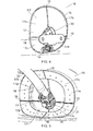
- FIG 4 illustrates a flap seal 17 (a "first seal") fixed adjacent the aperture 15.
- the flap seal 17 includes a plurality of flap seal portions and in the embodiment depicted in Figures 4 and 5 the flap seal 17 includes four flap seal portions including two upper flap seal portions 17a, 17b and two lower flap seal portions 17c and 17d.
- the flap seal portions 17a-d are discrete seal elements individually fastened to the interior surface of a D-nose panel 18 defining the fixed leading edge profile.
- the flap seal portions 17a-d are arranged so as to provide a clearance gap 19 between each adjacent flap seal section 17a-d.
- the flap seal 17 has a stepped configuration including a mounting portion 17e surrounding substantially the entire circumference of the generally elliptical aperture 15 (save for the gaps 19) and which mounting portion 17e is fastened to the reverse face of the D-nose panel 18.
- the flap seal 17 further includes a free portion 17f projecting into the aperture 15.
- the free portion 17f is arranged substantially flush with the outer surface of the D-nose panel 18.
- the flap seal 17 includes an intermediate portion 17g connecting the free portion 17f to the mounting portion 17e which traverses the wall thickness of the D-nose panel 18 around the circumferential edge of the aperture 15.
- the free portion 17f of the flap seal is configured to deflect as the strut 12 of the translating cable device 9 moves between its extended and retracted positions driven passively by movement of the slat 6.
- the flap seal 17 is arranged to seal a respective quadrant of the generally elliptical aperture 15, although the upper seal section s17a, b are larger than the lower seal sections 17c, d.
- the flap seal 17 further defines a cut-out 20 located generally centrally within the flap seal 17.
- the cut-out 20 is sized larger than the outer diameter of the strut 12 but smaller than a maximum "diameter" of the coupling 21 used to connect the distal end 14 of the strut 12 to the slat 6.
- coupling 21 extends either side of the flap seal 17 when the slat 6 is retracted for the cruise condition.
- the seal assembly includes a "second seal" fixed to the strut 12 of the translating cable device 9 such that the first and second seals cooperate to provide an enhanced sealing effect.
- the second seal is a plug seal 23, best shown in Figures 6 and 7 .
- the plug seal 23 is arranged to enter the aperture 15 in the D-nose panel 18 defining the fixed leading edge when the slat is fully extended (i.e. to its landing position), and to withdraw from the aperture 15 into the wing leading edge region behind the D-nose panel 18 when the slat is retracted.
- the plug seal 23 includes a mounting portion 23a formed generally as a sleeve for fixing to the tubular strut 12 at its proximal end 13.
- the plug seal 23 further comprises a generally elliptical sealing face 23b shaped to generally correspond with the shape of the elliptical aperture 15 but sized smaller than the edges of the aperture 15.
- the sealing face 23b is set at an oblique angle to the longitudinal axis of the strut 12 and is supported by a conical form 23c so as to blend into the sleeve section 23a.
- the plug seal 23 is generally rigid as compared with the flap seal 17.
- the plug seal 23 may be generally solid, or alternatively for weight saving the plug seal 23 may include internal voids.
- the flap seal 17 has been removed from around the aperture 15 in Figure 7 for clarity.
- the sealing face 23b contacts the interior surface of the free portion 17f of the flap seal 17 so as to provide an improved sealing effect.
- the plug seal 23 has the effect of preventing any significant inward deflection of the flap seal quadrants 17a-d due to the oncoming airflow, to seal the gaps 19 between the flap seal quadrants 17a-d, and also to fill the cut-out 20 in the flap seal 17.
- the flap seal 17 and the plug seal 23 provide an excellent sealing effect so as to substantially aerodynamically seal the aperture 15 in the fixed leading edge 7 when the slat 6 is fully deployed to its landing position.
- the seal assembly therefore includes a further seal element, in the form of a seal boot 24 shown in Figure 8 .
- the seal boot 24 is considered to be another "second seal" since, in addition to providing a protective cover over the coupling 21 for protecting the flap seal 17, the seal boot 24 is arranged to cooperate with the flap seal 17 so as to provide an improved sealing effect when the slat 6 is in its fully retracted (cruise) position.
- the seal assembly includes a plurality of "second seals" (the plug seal 23 and the boot seal 24) each adapted to cooperate with the "first seal” (the flap seal 17) at respective different positions of the slat 6.
- the seals may include various seal materials, and each of the seals may be constructed differently.
- the seals 17, 23, 24 are exposed to cold temperature environments.
- the flap seal 17 may be sufficiently flexible yet sufficiently abrasion resistant to accommodate movement of the strut.
- the boot seal 24 may also be flexible yet abrasion resistant.
- the plug seal 23 may be less flexible than the flap seal 17.
- Suitable seal materials for the flap seal 17 may include, for example, a reinforced silicone rubber or other elastomer.
- a fluoro-silicone material may be preferable.
- the reinforcement may include a fabric, such as a woven or knitted fibre layer.
- the fibres may be of polyester, cotton or any other suitable material.
- the outer surface of the flap seal 17 may include an environmental protection layer, such as a polyurethane coating.
- the flap seal 17 may be moulded or otherwise formed. Similar materials may also be used for the seal boot 23.
- the plug seal 24 may be stiffer than the flap seal 17.
- the plug seal 24 is also exposed to cold temperature environments, but generally has lower abrasion and flexibility requirements than the flap seal 17.
- the plug seal 24 may therefore be constructed of a variety of materials, such as a phenolic resin with a woven fabric (e.g. Tufnol), a soft elastomer, an aluminium composite, or a combination of these.
- the seal materials may need to be fire retardant to a particular level.
- the boot seal 24 encapsulates the coupling 21 and is formed generally as a sheath having a proximal end 24a wrapped around the distal end 14 of the strut 12, and a distal end 24b for sealing against the aft face of the slat 6.
- the seal boot 24 provides protection to the edges of the cut-out 20 in the flap seal 17 from protruding relatively sharp edges of the coupling 21.
- the boot seal 24 also occupies the cut-out 20 in the flap seal 17 when the slat 6 is fully retracted so as to provide an improved sealing effect when the slat 6 is fully retracted.
- seal boot 24 provides a more aerodynamic surface around the coupling 21 so as to reduce aerodynamic drag and noise created when the distal end 14 of the strut 12 is projected into the airflow within the cove region immediately behind the slat 6 when the slat is partially or fully deployed for the take off or landing high lift configurations.
- FIG. 9 shows a telescopic translating cable device 25 arranged to provide a similar function of electrically connecting the slat 6 to the wing 2.
- the telescopic translating cable device includes a strut in three sections, which move telescopically as the slat 6 moves between its retracted and extended positions.
- the aircraft wing assembly shown in Figure 9 also includes the flap seal 17 in the fixed leading edge 7, the plug seal 23 fixed to the outside of the strut, and the seal boot 24 around the coupling 21 between a distal end of the telescopic translating cable device 25 and the slat 6.
- the flap seal 17, the plug seal 23 and the seal boot 24 are arranged and function substantially identically to the embodiment described above.
- the plug seal 23 is fixed to the middle one of the three telescopic strut sections, adjacent a distal end thereof nearest the slat 6.
- the telescopic strut can have greater or fewer sections than three.
Landscapes
- Engineering & Computer Science (AREA)
- Aviation & Aerospace Engineering (AREA)
- Sealing Devices (AREA)
- Mechanical Engineering (AREA)
- Automation & Control Theory (AREA)
- Installation Of Indoor Wiring (AREA)
- Lift Valve (AREA)
- Connector Housings Or Holding Contact Members (AREA)
Applications Claiming Priority (1)
| Application Number | Priority Date | Filing Date | Title |
|---|---|---|---|
| GBGB1121447.5A GB201121447D0 (en) | 2011-12-14 | 2011-12-14 | Translating cable device sealing |
Publications (3)
| Publication Number | Publication Date |
|---|---|
| EP2604512A2 true EP2604512A2 (de) | 2013-06-19 |
| EP2604512A3 EP2604512A3 (de) | 2016-05-18 |
| EP2604512B1 EP2604512B1 (de) | 2020-02-12 |
Family
ID=45560417
Family Applications (1)
| Application Number | Title | Priority Date | Filing Date |
|---|---|---|---|
| EP12195396.2A Active EP2604512B1 (de) | 2011-12-14 | 2012-12-04 | Dichtung für verschiebbare Kabeleinrichtung |
Country Status (7)
| Country | Link |
|---|---|
| US (1) | US9027890B2 (de) |
| EP (1) | EP2604512B1 (de) |
| JP (1) | JP2013124096A (de) |
| CN (1) | CN103158862B (de) |
| CA (1) | CA2797715A1 (de) |
| GB (1) | GB201121447D0 (de) |
| RU (1) | RU2012153236A (de) |
Cited By (2)
| Publication number | Priority date | Publication date | Assignee | Title |
|---|---|---|---|---|
| WO2016125094A1 (en) * | 2015-02-05 | 2016-08-11 | Bombardier Inc. | Apparatus for obstructing air flow through an aperture for a duct in an aircraft wing |
| WO2017216691A1 (en) * | 2016-06-17 | 2017-12-21 | Bombardier Inc. | Panels for obstructing air flow through apertures in an aircraft wing |
Families Citing this family (8)
| Publication number | Priority date | Publication date | Assignee | Title |
|---|---|---|---|---|
| CN105015763B (zh) * | 2014-04-21 | 2017-01-04 | 哈尔滨飞机工业集团有限责任公司 | 一种飞机操纵钢索导向件 |
| EP3339165B1 (de) * | 2016-12-22 | 2020-09-09 | Goodrich Actuation Systems Limited | Flügelvorflügelaktuatortrennungserkennung |
| CN108177761A (zh) * | 2017-12-14 | 2018-06-19 | 中国航空工业集团公司成都飞机设计研究所 | 一种适用于大展弦比机翼的全复合材料翼尖小翼 |
| US10800511B2 (en) * | 2018-05-31 | 2020-10-13 | The Boeing Company | End seal device for a high-lift device of an aircraft |
| KR200489370Y1 (ko) * | 2018-12-17 | 2019-09-27 | 국방기술품질원 | 무인 항공기용 이물질 차단 장치 및 이를 포함하는 무인 항공기 |
| US11420727B2 (en) | 2019-07-25 | 2022-08-23 | Airbus Operations Gmbh | Airfoil arrangement for an aircraft |
| CN110641682A (zh) * | 2019-11-26 | 2020-01-03 | 中国商用飞机有限责任公司 | 摇臂式运动线缆机构 |
| CN114421375B (zh) * | 2022-01-20 | 2023-09-05 | 中国商用飞机有限责任公司 | 用于飞机固定前缘和缝翼的线缆引导装置 |
Family Cites Families (13)
| Publication number | Priority date | Publication date | Assignee | Title |
|---|---|---|---|---|
| GB1572004A (en) * | 1978-03-30 | 1980-07-23 | Hawker Siddeley Aviation Ltd | Aircraft wings |
| GB9607707D0 (en) | 1996-04-13 | 1996-06-19 | Broadbent Michael C | A self-sealing parallelogram slat mechanism |
| US6015117A (en) * | 1996-04-13 | 2000-01-18 | Broadbent; Michael C | Variable camber wing mechanism |
| US6164660A (en) * | 1998-04-16 | 2000-12-26 | Saint-Gobain Performance Plastics Corporation | Rebuildable radial lip seal |
| GB0012176D0 (en) | 2000-05-20 | 2000-07-12 | Broadbent Michael C | Deployment system for a moveable wing surface |
| CA2515276A1 (en) * | 2004-08-23 | 2006-02-23 | Goodrich Corporation | Aircraft wing |
| GB2417937B (en) * | 2004-09-10 | 2009-08-12 | Ultra Electronics Ltd | An aircraft wing coupling arrangement |
| US7249735B2 (en) * | 2005-06-30 | 2007-07-31 | The Boeing Company | Translating conduit apparatus for an airplane or equipment |
| US20090078084A1 (en) * | 2007-09-21 | 2009-03-26 | Richard Alfred Compau | Boot Cover Assembly |
| GB0807626D0 (en) | 2008-04-25 | 2008-06-04 | Ultra Electronics Ltd | Routing of cables |
| GB0911016D0 (en) * | 2009-06-25 | 2009-08-12 | Airbus Operations Ltd | Electrical power transmitting telescopic strut |
| GB0913128D0 (en) * | 2009-07-29 | 2009-09-02 | Airbus Operations Ltd | Electrical power transfer assembly |
| GB201011378D0 (en) * | 2010-07-06 | 2010-08-18 | Ultra Electronics Ltd | Linkage for guiding a flexible cable |
-
2011
- 2011-12-14 GB GBGB1121447.5A patent/GB201121447D0/en not_active Ceased
-
2012
- 2012-11-29 CA CA2797715A patent/CA2797715A1/en not_active Abandoned
- 2012-12-04 EP EP12195396.2A patent/EP2604512B1/de active Active
- 2012-12-05 JP JP2012266138A patent/JP2013124096A/ja active Pending
- 2012-12-11 RU RU2012153236/11A patent/RU2012153236A/ru not_active Application Discontinuation
- 2012-12-14 US US13/714,701 patent/US9027890B2/en active Active
- 2012-12-14 CN CN201210543687.4A patent/CN103158862B/zh active Active
Cited By (5)
| Publication number | Priority date | Publication date | Assignee | Title |
|---|---|---|---|---|
| WO2016125094A1 (en) * | 2015-02-05 | 2016-08-11 | Bombardier Inc. | Apparatus for obstructing air flow through an aperture for a duct in an aircraft wing |
| US10899430B2 (en) * | 2015-02-05 | 2021-01-26 | Airbus Canada Limited Partnership | Apparatus for obstructing air flow through an aperture for a duct in an aircraft wing |
| WO2017216691A1 (en) * | 2016-06-17 | 2017-12-21 | Bombardier Inc. | Panels for obstructing air flow through apertures in an aircraft wing |
| US11192625B2 (en) | 2016-06-17 | 2021-12-07 | Bombardier Inc. | Panels for obstructing air flow through apertures in an aircraft wing |
| US11718385B2 (en) | 2016-06-17 | 2023-08-08 | Bombardier Inc. | Panels for obstructing air flow through apertures in an aircraft wing |
Also Published As
| Publication number | Publication date |
|---|---|
| EP2604512B1 (de) | 2020-02-12 |
| JP2013124096A (ja) | 2013-06-24 |
| CN103158862B (zh) | 2017-03-01 |
| US20130153713A1 (en) | 2013-06-20 |
| GB201121447D0 (en) | 2012-01-25 |
| CN103158862A (zh) | 2013-06-19 |
| US9027890B2 (en) | 2015-05-12 |
| RU2012153236A (ru) | 2014-06-20 |
| EP2604512A3 (de) | 2016-05-18 |
| CA2797715A1 (en) | 2013-06-14 |
Similar Documents
| Publication | Publication Date | Title |
|---|---|---|
| EP2604512B1 (de) | Dichtung für verschiebbare Kabeleinrichtung | |
| US7249735B2 (en) | Translating conduit apparatus for an airplane or equipment | |
| RU2429168C2 (ru) | Силовая установка летательного аппарата, содержащая смонтированный на двух отдельных элементах ложемент, несущий корпус вентилятора | |
| US20110024566A1 (en) | Electrical power transfer assmebly | |
| CA2927577C (en) | Pinned fuselage-to-wing connection | |
| US20060038088A1 (en) | Aircraft wing | |
| US9567059B2 (en) | Externally mounted auxiliary door for an aircraft | |
| US20170197700A1 (en) | Electric distributed propulsion and high lift system | |
| US8408500B2 (en) | Cable carrier chain for leading edge mobile slat for an aircraft wing | |
| US8439311B2 (en) | Aerial refueling boom and boom pivot | |
| US20110049293A1 (en) | retractable undercarriage for an aircraft | |
| US20140319269A1 (en) | Inner cowl structure for aircraft turbine engine | |
| CN110877742A (zh) | 涡轮风扇发动机和飞行器 | |
| EP4227212B1 (de) | Flugzeugflügel | |
| US10899430B2 (en) | Apparatus for obstructing air flow through an aperture for a duct in an aircraft wing | |
| CN104254481B (zh) | 有下游段的涡轮喷气发动机机舱 | |
| US20150344158A1 (en) | Space aircraft | |
| US20200369397A1 (en) | Propulsion assembly for an aircraft, comprising a load support | |
| US20250388332A1 (en) | Aerial refuelling drogue assembly stabilization and guidance system | |
| EP3990351B1 (de) | Eintrittskantenanordnung für ein flugzeug | |
| US11845550B2 (en) | Wing leading-edge device and a wing having such a wing leading-edge device | |
| US20160137286A1 (en) | Shape-variable gap covering between control surfaces and adjacent structural components on aircrafts | |
| EP1135291A1 (de) | Einziehbare sondenanordnung für flugzeuge |
Legal Events
| Date | Code | Title | Description |
|---|---|---|---|
| PUAI | Public reference made under article 153(3) epc to a published international application that has entered the european phase |
Free format text: ORIGINAL CODE: 0009012 |
|
| AK | Designated contracting states |
Kind code of ref document: A2 Designated state(s): AL AT BE BG CH CY CZ DE DK EE ES FI FR GB GR HR HU IE IS IT LI LT LU LV MC MK MT NL NO PL PT RO RS SE SI SK SM TR |
|
| AX | Request for extension of the european patent |
Extension state: BA ME |
|
| PUAL | Search report despatched |
Free format text: ORIGINAL CODE: 0009013 |
|
| AK | Designated contracting states |
Kind code of ref document: A3 Designated state(s): AL AT BE BG CH CY CZ DE DK EE ES FI FR GB GR HR HU IE IS IT LI LT LU LV MC MK MT NL NO PL PT RO RS SE SI SK SM TR |
|
| AX | Request for extension of the european patent |
Extension state: BA ME |
|
| RIC1 | Information provided on ipc code assigned before grant |
Ipc: B64C 9/22 20060101AFI20160411BHEP |
|
| STAA | Information on the status of an ep patent application or granted ep patent |
Free format text: STATUS: REQUEST FOR EXAMINATION WAS MADE |
|
| 17P | Request for examination filed |
Effective date: 20161118 |
|
| RBV | Designated contracting states (corrected) |
Designated state(s): AL AT BE BG CH CY CZ DE DK EE ES FI FR GB GR HR HU IE IS IT LI LT LU LV MC MK MT NL NO PL PT RO RS SE SI SK SM TR |
|
| STAA | Information on the status of an ep patent application or granted ep patent |
Free format text: STATUS: EXAMINATION IS IN PROGRESS |
|
| 17Q | First examination report despatched |
Effective date: 20190212 |
|
| GRAP | Despatch of communication of intention to grant a patent |
Free format text: ORIGINAL CODE: EPIDOSNIGR1 |
|
| STAA | Information on the status of an ep patent application or granted ep patent |
Free format text: STATUS: GRANT OF PATENT IS INTENDED |
|
| INTG | Intention to grant announced |
Effective date: 20190816 |
|
| GRAS | Grant fee paid |
Free format text: ORIGINAL CODE: EPIDOSNIGR3 |
|
| GRAA | (expected) grant |
Free format text: ORIGINAL CODE: 0009210 |
|
| STAA | Information on the status of an ep patent application or granted ep patent |
Free format text: STATUS: THE PATENT HAS BEEN GRANTED |
|
| AK | Designated contracting states |
Kind code of ref document: B1 Designated state(s): AL AT BE BG CH CY CZ DE DK EE ES FI FR GB GR HR HU IE IS IT LI LT LU LV MC MK MT NL NO PL PT RO RS SE SI SK SM TR |
|
| REG | Reference to a national code |
Ref country code: GB Ref legal event code: FG4D |
|
| REG | Reference to a national code |
Ref country code: CH Ref legal event code: EP |
|
| REG | Reference to a national code |
Ref country code: AT Ref legal event code: REF Ref document number: 1231759 Country of ref document: AT Kind code of ref document: T Effective date: 20200215 |
|
| REG | Reference to a national code |
Ref country code: DE Ref legal event code: R096 Ref document number: 602012067669 Country of ref document: DE |
|
| REG | Reference to a national code |
Ref country code: IE Ref legal event code: FG4D |
|
| PG25 | Lapsed in a contracting state [announced via postgrant information from national office to epo] |
Ref country code: RS Free format text: LAPSE BECAUSE OF FAILURE TO SUBMIT A TRANSLATION OF THE DESCRIPTION OR TO PAY THE FEE WITHIN THE PRESCRIBED TIME-LIMIT Effective date: 20200212 Ref country code: NO Free format text: LAPSE BECAUSE OF FAILURE TO SUBMIT A TRANSLATION OF THE DESCRIPTION OR TO PAY THE FEE WITHIN THE PRESCRIBED TIME-LIMIT Effective date: 20200512 Ref country code: FI Free format text: LAPSE BECAUSE OF FAILURE TO SUBMIT A TRANSLATION OF THE DESCRIPTION OR TO PAY THE FEE WITHIN THE PRESCRIBED TIME-LIMIT Effective date: 20200212 |
|
| REG | Reference to a national code |
Ref country code: LT Ref legal event code: MG4D |
|
| REG | Reference to a national code |
Ref country code: NL Ref legal event code: MP Effective date: 20200212 |
|
| PG25 | Lapsed in a contracting state [announced via postgrant information from national office to epo] |
Ref country code: LV Free format text: LAPSE BECAUSE OF FAILURE TO SUBMIT A TRANSLATION OF THE DESCRIPTION OR TO PAY THE FEE WITHIN THE PRESCRIBED TIME-LIMIT Effective date: 20200212 Ref country code: IS Free format text: LAPSE BECAUSE OF FAILURE TO SUBMIT A TRANSLATION OF THE DESCRIPTION OR TO PAY THE FEE WITHIN THE PRESCRIBED TIME-LIMIT Effective date: 20200612 Ref country code: SE Free format text: LAPSE BECAUSE OF FAILURE TO SUBMIT A TRANSLATION OF THE DESCRIPTION OR TO PAY THE FEE WITHIN THE PRESCRIBED TIME-LIMIT Effective date: 20200212 Ref country code: HR Free format text: LAPSE BECAUSE OF FAILURE TO SUBMIT A TRANSLATION OF THE DESCRIPTION OR TO PAY THE FEE WITHIN THE PRESCRIBED TIME-LIMIT Effective date: 20200212 Ref country code: BG Free format text: LAPSE BECAUSE OF FAILURE TO SUBMIT A TRANSLATION OF THE DESCRIPTION OR TO PAY THE FEE WITHIN THE PRESCRIBED TIME-LIMIT Effective date: 20200512 Ref country code: GR Free format text: LAPSE BECAUSE OF FAILURE TO SUBMIT A TRANSLATION OF THE DESCRIPTION OR TO PAY THE FEE WITHIN THE PRESCRIBED TIME-LIMIT Effective date: 20200513 |
|
| PG25 | Lapsed in a contracting state [announced via postgrant information from national office to epo] |
Ref country code: NL Free format text: LAPSE BECAUSE OF FAILURE TO SUBMIT A TRANSLATION OF THE DESCRIPTION OR TO PAY THE FEE WITHIN THE PRESCRIBED TIME-LIMIT Effective date: 20200212 |
|
| PG25 | Lapsed in a contracting state [announced via postgrant information from national office to epo] |
Ref country code: DK Free format text: LAPSE BECAUSE OF FAILURE TO SUBMIT A TRANSLATION OF THE DESCRIPTION OR TO PAY THE FEE WITHIN THE PRESCRIBED TIME-LIMIT Effective date: 20200212 Ref country code: SK Free format text: LAPSE BECAUSE OF FAILURE TO SUBMIT A TRANSLATION OF THE DESCRIPTION OR TO PAY THE FEE WITHIN THE PRESCRIBED TIME-LIMIT Effective date: 20200212 Ref country code: EE Free format text: LAPSE BECAUSE OF FAILURE TO SUBMIT A TRANSLATION OF THE DESCRIPTION OR TO PAY THE FEE WITHIN THE PRESCRIBED TIME-LIMIT Effective date: 20200212 Ref country code: SM Free format text: LAPSE BECAUSE OF FAILURE TO SUBMIT A TRANSLATION OF THE DESCRIPTION OR TO PAY THE FEE WITHIN THE PRESCRIBED TIME-LIMIT Effective date: 20200212 Ref country code: PT Free format text: LAPSE BECAUSE OF FAILURE TO SUBMIT A TRANSLATION OF THE DESCRIPTION OR TO PAY THE FEE WITHIN THE PRESCRIBED TIME-LIMIT Effective date: 20200705 Ref country code: LT Free format text: LAPSE BECAUSE OF FAILURE TO SUBMIT A TRANSLATION OF THE DESCRIPTION OR TO PAY THE FEE WITHIN THE PRESCRIBED TIME-LIMIT Effective date: 20200212 Ref country code: CZ Free format text: LAPSE BECAUSE OF FAILURE TO SUBMIT A TRANSLATION OF THE DESCRIPTION OR TO PAY THE FEE WITHIN THE PRESCRIBED TIME-LIMIT Effective date: 20200212 Ref country code: RO Free format text: LAPSE BECAUSE OF FAILURE TO SUBMIT A TRANSLATION OF THE DESCRIPTION OR TO PAY THE FEE WITHIN THE PRESCRIBED TIME-LIMIT Effective date: 20200212 Ref country code: ES Free format text: LAPSE BECAUSE OF FAILURE TO SUBMIT A TRANSLATION OF THE DESCRIPTION OR TO PAY THE FEE WITHIN THE PRESCRIBED TIME-LIMIT Effective date: 20200212 |
|
| REG | Reference to a national code |
Ref country code: DE Ref legal event code: R097 Ref document number: 602012067669 Country of ref document: DE |
|
| REG | Reference to a national code |
Ref country code: AT Ref legal event code: MK05 Ref document number: 1231759 Country of ref document: AT Kind code of ref document: T Effective date: 20200212 |
|
| PLBE | No opposition filed within time limit |
Free format text: ORIGINAL CODE: 0009261 |
|
| STAA | Information on the status of an ep patent application or granted ep patent |
Free format text: STATUS: NO OPPOSITION FILED WITHIN TIME LIMIT |
|
| 26N | No opposition filed |
Effective date: 20201113 |
|
| PG25 | Lapsed in a contracting state [announced via postgrant information from national office to epo] |
Ref country code: IT Free format text: LAPSE BECAUSE OF FAILURE TO SUBMIT A TRANSLATION OF THE DESCRIPTION OR TO PAY THE FEE WITHIN THE PRESCRIBED TIME-LIMIT Effective date: 20200212 Ref country code: AT Free format text: LAPSE BECAUSE OF FAILURE TO SUBMIT A TRANSLATION OF THE DESCRIPTION OR TO PAY THE FEE WITHIN THE PRESCRIBED TIME-LIMIT Effective date: 20200212 |
|
| PG25 | Lapsed in a contracting state [announced via postgrant information from national office to epo] |
Ref country code: SI Free format text: LAPSE BECAUSE OF FAILURE TO SUBMIT A TRANSLATION OF THE DESCRIPTION OR TO PAY THE FEE WITHIN THE PRESCRIBED TIME-LIMIT Effective date: 20200212 Ref country code: PL Free format text: LAPSE BECAUSE OF FAILURE TO SUBMIT A TRANSLATION OF THE DESCRIPTION OR TO PAY THE FEE WITHIN THE PRESCRIBED TIME-LIMIT Effective date: 20200212 |
|
| REG | Reference to a national code |
Ref country code: CH Ref legal event code: PL |
|
| PG25 | Lapsed in a contracting state [announced via postgrant information from national office to epo] |
Ref country code: MC Free format text: LAPSE BECAUSE OF FAILURE TO SUBMIT A TRANSLATION OF THE DESCRIPTION OR TO PAY THE FEE WITHIN THE PRESCRIBED TIME-LIMIT Effective date: 20200212 |
|
| REG | Reference to a national code |
Ref country code: BE Ref legal event code: MM Effective date: 20201231 |
|
| PG25 | Lapsed in a contracting state [announced via postgrant information from national office to epo] |
Ref country code: LU Free format text: LAPSE BECAUSE OF NON-PAYMENT OF DUE FEES Effective date: 20201204 Ref country code: IE Free format text: LAPSE BECAUSE OF NON-PAYMENT OF DUE FEES Effective date: 20201204 |
|
| PG25 | Lapsed in a contracting state [announced via postgrant information from national office to epo] |
Ref country code: LI Free format text: LAPSE BECAUSE OF NON-PAYMENT OF DUE FEES Effective date: 20201231 Ref country code: CH Free format text: LAPSE BECAUSE OF NON-PAYMENT OF DUE FEES Effective date: 20201231 |
|
| PG25 | Lapsed in a contracting state [announced via postgrant information from national office to epo] |
Ref country code: TR Free format text: LAPSE BECAUSE OF FAILURE TO SUBMIT A TRANSLATION OF THE DESCRIPTION OR TO PAY THE FEE WITHIN THE PRESCRIBED TIME-LIMIT Effective date: 20200212 Ref country code: MT Free format text: LAPSE BECAUSE OF FAILURE TO SUBMIT A TRANSLATION OF THE DESCRIPTION OR TO PAY THE FEE WITHIN THE PRESCRIBED TIME-LIMIT Effective date: 20200212 Ref country code: CY Free format text: LAPSE BECAUSE OF FAILURE TO SUBMIT A TRANSLATION OF THE DESCRIPTION OR TO PAY THE FEE WITHIN THE PRESCRIBED TIME-LIMIT Effective date: 20200212 |
|
| PG25 | Lapsed in a contracting state [announced via postgrant information from national office to epo] |
Ref country code: MK Free format text: LAPSE BECAUSE OF FAILURE TO SUBMIT A TRANSLATION OF THE DESCRIPTION OR TO PAY THE FEE WITHIN THE PRESCRIBED TIME-LIMIT Effective date: 20200212 Ref country code: AL Free format text: LAPSE BECAUSE OF FAILURE TO SUBMIT A TRANSLATION OF THE DESCRIPTION OR TO PAY THE FEE WITHIN THE PRESCRIBED TIME-LIMIT Effective date: 20200212 |
|
| PG25 | Lapsed in a contracting state [announced via postgrant information from national office to epo] |
Ref country code: BE Free format text: LAPSE BECAUSE OF NON-PAYMENT OF DUE FEES Effective date: 20201231 |
|
| PGFP | Annual fee paid to national office [announced via postgrant information from national office to epo] |
Ref country code: DE Payment date: 20251211 Year of fee payment: 14 |
|
| PGFP | Annual fee paid to national office [announced via postgrant information from national office to epo] |
Ref country code: GB Payment date: 20251219 Year of fee payment: 14 |
|
| PGFP | Annual fee paid to national office [announced via postgrant information from national office to epo] |
Ref country code: FR Payment date: 20251223 Year of fee payment: 14 |