EP2604150B1 - Facility comprising food and drink infrastructure, and method of attracting customers to said facility - Google Patents
Facility comprising food and drink infrastructure, and method of attracting customers to said facility Download PDFInfo
- Publication number
- EP2604150B1 EP2604150B1 EP11816205.6A EP11816205A EP2604150B1 EP 2604150 B1 EP2604150 B1 EP 2604150B1 EP 11816205 A EP11816205 A EP 11816205A EP 2604150 B1 EP2604150 B1 EP 2604150B1
- Authority
- EP
- European Patent Office
- Prior art keywords
- rotating body
- facility
- drive motor
- rotating
- caster
- Prior art date
- Legal status (The legal status is an assumption and is not a legal conclusion. Google has not performed a legal analysis and makes no representation as to the accuracy of the status listed.)
- Not-in-force
Links
- 235000013305 food Nutrition 0.000 title claims description 14
- 238000000034 method Methods 0.000 title claims description 13
- 239000000758 substrate Substances 0.000 claims description 35
- 239000000126 substance Substances 0.000 description 8
- XEEYBQQBJWHFJM-UHFFFAOYSA-N Iron Chemical compound [Fe] XEEYBQQBJWHFJM-UHFFFAOYSA-N 0.000 description 4
- 230000001276 controlling effect Effects 0.000 description 2
- 230000008878 coupling Effects 0.000 description 2
- 238000010168 coupling process Methods 0.000 description 2
- 238000005859 coupling reaction Methods 0.000 description 2
- 229910052742 iron Inorganic materials 0.000 description 2
- 230000009194 climbing Effects 0.000 description 1
- 230000001419 dependent effect Effects 0.000 description 1
- 230000035622 drinking Effects 0.000 description 1
- 238000005516 engineering process Methods 0.000 description 1
- 238000012423 maintenance Methods 0.000 description 1
- 235000012054 meals Nutrition 0.000 description 1
- 230000001105 regulatory effect Effects 0.000 description 1
- 238000006467 substitution reaction Methods 0.000 description 1
Images


Classifications
-
- A—HUMAN NECESSITIES
- A47—FURNITURE; DOMESTIC ARTICLES OR APPLIANCES; COFFEE MILLS; SPICE MILLS; SUCTION CLEANERS IN GENERAL
- A47F—SPECIAL FURNITURE, FITTINGS, OR ACCESSORIES FOR SHOPS, STOREHOUSES, BARS, RESTAURANTS OR THE LIKE; PAYING COUNTERS
- A47F10/00—Furniture or installations specially adapted to particular types of service systems, not otherwise provided for
- A47F10/06—Furniture or installations specially adapted to particular types of service systems, not otherwise provided for for restaurant service systems
-
- A—HUMAN NECESSITIES
- A47—FURNITURE; DOMESTIC ARTICLES OR APPLIANCES; COFFEE MILLS; SPICE MILLS; SUCTION CLEANERS IN GENERAL
- A47B—TABLES; DESKS; OFFICE FURNITURE; CABINETS; DRAWERS; GENERAL DETAILS OF FURNITURE
- A47B11/00—Tables with tops revolvable on vertical spindles
-
- A—HUMAN NECESSITIES
- A63—SPORTS; GAMES; AMUSEMENTS
- A63G—MERRY-GO-ROUNDS; SWINGS; ROCKING-HORSES; CHUTES; SWITCHBACKS; SIMILAR DEVICES FOR PUBLIC AMUSEMENT
- A63G1/00—Roundabouts
- A63G1/08—Roundabouts power-driven
- A63G1/10—Roundabouts power-driven electrically driven
-
- A—HUMAN NECESSITIES
- A63—SPORTS; GAMES; AMUSEMENTS
- A63G—MERRY-GO-ROUNDS; SWINGS; ROCKING-HORSES; CHUTES; SWITCHBACKS; SIMILAR DEVICES FOR PUBLIC AMUSEMENT
- A63G31/00—Amusement arrangements
- A63G31/02—Amusement arrangements with moving substructures
-
- B—PERFORMING OPERATIONS; TRANSPORTING
- B60—VEHICLES IN GENERAL
- B60P—VEHICLES ADAPTED FOR LOAD TRANSPORTATION OR TO TRANSPORT, TO CARRY, OR TO COMPRISE SPECIAL LOADS OR OBJECTS
- B60P3/00—Vehicles adapted to transport, to carry or to comprise special loads or objects
- B60P3/025—Vehicles adapted to transport, to carry or to comprise special loads or objects the object being a shop, cafeteria or display the object being a theatre or stage
- B60P3/0257—Vehicles adapted to transport, to carry or to comprise special loads or objects the object being a shop, cafeteria or display the object being a theatre or stage the object being a vending stall, restaurant or food kiosk
-
- E—FIXED CONSTRUCTIONS
- E04—BUILDING
- E04H—BUILDINGS OR LIKE STRUCTURES FOR PARTICULAR PURPOSES; SWIMMING OR SPLASH BATHS OR POOLS; MASTS; FENCING; TENTS OR CANOPIES, IN GENERAL
- E04H3/00—Buildings or groups of buildings for public or similar purposes; Institutions, e.g. infirmaries or prisons
- E04H3/02—Hotels; Motels; Coffee-houses; Restaurants; Shops; Department stores
- E04H3/04—Restaurants or shops having arrangements for self-service
Definitions
- This Invention relates to facility comprising food and drink infrastructure and method of attracting customers to said facility.
- the facilities such as food courts (meaning an indoor space for providing a variety of adjacent restaurant booth and a shared space for self-service meals, the same shall apply hereinafter) are spreading rapidly in a shopping mall and an airport. Because seats can be commonly used by dividing the shop by each menu regarding the cuisine, every shop doesn't need the seats. Furthermore, it is used by many families because the seat portion (hereinafter called a sharing space) can be set widely.
- the food court is disclosed with reference to the technology of the call system in the patent document of the related art Japanese Registered Utility Model No. 3158842 .
- An object of the present invention is to make available a facility capable of making the further more interest of customers, and method of attracting customers to said facility, in the facilities where a plurality of store has a shared seat (sharing space).
- the rotating table may be configured by placing a table and a chair to the rotating device, the travelling wheeled vehicle and the rotating tables are positioned in the shared space.
- the upper rotation body may be rotated by the crank rotated by drive motor. Furthermore, by a caster's supporting the load coming from the upper part, the small rotation device strong about weight coming from the upper part can be easily configured thus without complicated mechanism. Furthermore, by placing the travelling wheeled vehicle in the sharing space, customers become able to board travelling wheeled vehicle.
- a lower rotating body for fixing the above drive motor may be provided to the rotating device, an upper rotating body is stacked in the lower rotating body while aligning their central axes. And, placing a caster for supporting the upper rotating body to the lower rotation body, in the state a wheel of the caster upturned.
- the invention enables customers to eat in the vehicle by employing the table to the travelling wheeled vehicle. Furthermore, a crank placed in the centre of top surface of the base substance and rotating shaft for pivotally supporting the crank is rotationally driven by a drive motor, thus the upper rotating body makes eccentric rotating.
- the facility may comprise a plurality of stores that offer food and drink, and that treats customer seating for the plurality of stores as a shared space. And, this facility comprises a travelling wheeled vehicle which is capable of carrying customers on a tour of the shared space and comprises a rotating table.
- the rotating devices comprises a base substance and comprises an upper rotating comprising a crank which is positioned in the centre of base substance.
- the rotating devices further comprises a drive motor capable of rotationally driving the crank, and casters that support the upper rotating body.
- the rotating table is configured by placing a table to the rotating device, and the travelling wheeled vehicle and the rotating tables are positioned in the shared space.
- a lower rotating body for fixing the above drive motor is provided to the rotating device, and the upper rotating body is stacked in the lower rotating body while aligning their central axes.
- a table may be comprised in the travelling wheeled vehicle.
- a crank placed in the centre of top surface of the base substance and rotating shaft for pivotally supporting the crank is rotationally driven by a drive motor, thus the upper rotating body makes eccentric rotating.
- a slip ring for supplying electric power to the playground equipment may be provided. Even if rotating device for playground equipments rotates, electric power is supplied to a playground equipment placed in the rotation device upper part. Furthermore, a torque limiter may be mounted in the rotation axis of the drive motor, for controlling a driving torque of the rotation axis within predetermined value.
- a playground equipment may be placed in the sharing space.
- the playground equipment such as climbing equipment, rotary playground equipment, iron rods, slide, swing, jungle gyms, aerial ladders, and seesaws and combination of playground equipment may be placed in the facility which placed in the sharing space of the present invention or method of attracting customers to a facility.
- the facility may comprise a plurality of stores that offer food and drink, and that treats customer seating for the plurality of stores as a shared space, or a method of attracting customers to the facility.
- this facility comprises a travelling wheeled vehicle, which is capable of carrying customers on a tour of the shared space and further comprises a rotating table.
- the rotating devices comprise a base substance and comprise an upper rotating body comprising a crank which is positioned in the centres of base substance.
- the rotating devices further comprise a drive motor capable of rotationally driving the central gears, and casters that support the upper rotating body.
- the rotating table may be configured by placing a table and a chair to the rotating device, and the travelling wheeled vehicle and the rotating tables are positioned in the shared space.
- the upper rotation body may be rotated by the crank rotated by drive motor. Furthermore, by a caster's supporting the load coming from the upper part, the small rotation device strong about weight coming from the upper part can be easily configured thus without complicated mechanism. Furthermore, by placing the travelling wheeled vehicle in the sharing space, customers become able to board travelling wheeled vehicle, so the customers of families can be attracted in facility of this Invention coming with the aim of above rotating table and travelling wheeled vehicle.
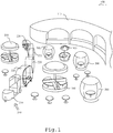
- FIG.1 is an outline schematic view showing whole configuration of facility 100
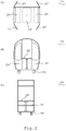
- FIG. 2 is a drawing of a travelling wheeled vehicle 200 provided to the facility 100
- FIG. 3 , FIG. 4 , and FIG. 5 show a drawing explaining a rotating table 300 provided in the facility 100.
- the facility 100 comprises a travelling wheeled vehicle 200 capable of travelling between seats in facility 100, and comprises a table provided on a rotating device 310. At first, a travelling wheeled vehicle 200 is explained.
- a travelling wheeled vehicle 200 comprises one leading vehicle 210 and one or more subsequent vehicle 220.
- a drive motor for coupling the subsequent vehicle 220 and travelling in the facility 100 is provided to the leading vehicle 210 provided to the travelling wheeled vehicle 200. And, the drive motor drives the driving wheel provided to the leading vehicle 210.
- a driver seat for seating of driver driving the leading vehicle 210 is comprised to the leading vehicle 210, and furthermore a handle capable of controlling the driving wheel is provided to the position capable of operating in the driver seat.
- Plurality of subsequent vehicle 220 is connected next to the leading vehicle 210.
- a configuration capable of coupling the leading vehicle 210 or other subsequent vehicle 220 is provided at the outside both ends of the subsequent vehicle 220.
- a subsequent seat 225 capable of sitting and a table 222 having the predetermined height is provided to the subsequent vehicle 220.
- any one of the subsequent vehicles 220 connects to the leading vehicle 210 by the joint member, and the subsequent vehicle 220 of the latter part connects to said one subsequent vehicle 220.
- Travelling wheeled vehicle 200 is configured by connecting the subsequent vehicles 220 required.
- a table 222 is provided in the subsequent vehicle 220, so the customers can eat in the subsequent vehicle 220.
- a door of the subsequent vehicle 220 with the door closed, a door has a clearance gap capable of placing the cuisines on the table of vehicle 220.
- a door on its left and right is formed of a double door, and with the double door closed, the table 222 in the vehicle 220 have a clearance gap of the degree capable of placing the cuisine plates.
- a chair (subsequent seat) 225 is formed, by attaching a seat board in such a way as to project from the side wall portion of the subsequent vehicle 220.
- a seat board is mounted on the side wall portion (the height the customers can sit).
- a rotating table 300 to eat in the state of rotating is provided in the facility 100.
- the rotating table 300 is configured by placing a table 222 and a chair 225 to the rotating device 310. That is, the table and chair rotates by rotating the rotating device 310.
- Above rotating device 310 comprise an upper rotating body and a bottom rotating body.
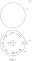
- the upper rotating body comprises top substrate 311 ( FIG. 3 shows circle -shaped substrate 311, but if trouble-free against rotation, it may be a rectangle and a polyline shape).
- a rail (not shown) for rotating the after-mentioned casters 324 may be placed to the upper rotation body 311.
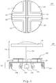
- a bottom substrate 320 comprises a central gear 327, a drive motor 326 for driving the central gear 327, and a caster 324.
- a central gear 327 is placed on centre location where the bottom substrate 320 (a circular shape is employed, but any shapes may be applied) for the bottom rotating body is seen from a top.
- an axis of revolution of the gear 327 is placed corresponding to the central axe of the bottom substrate 320.
- a drive motor 326 is placed to the vicinities of the central gear 327.
- a roller chain is wound on the centre gear 327 and the rotation axis of the drive motor 326, and it is configured so that the centre gear 327 rotates via the roller chain if the rotating shaft of the motor 326 rotates.
- plurality of caster 324 is placed to the bottom rotating body, in plane with the centre gear 327 and the drive motor 326.
- opposing casters 324 are placed symmetrically to the centre of bottom rotation body( bottom substrate), and adjacent casters are placed at equal intervals.
- the upper substrate 311 rotates depending on rotation of the casters 324. Therefore, the casters 324 of the bottom substrate 320 support the upper substrate 311.
- top substrate 311 and bottom substrate 320 are combined.
- the bottom substrate 320 is placed on the floor.
- the upper substrate 311 is piled on the bottom substrate 320.
- the rotating device 310 is formed by engaging the centre gear 327 to the upper substrate 311 so that the upper substrate 311 rotates when centre gear 327 of the bottom substrate 320 rotates.
- the centre gear 327 is engaged removable to the upper substrate 311.
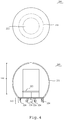
- the rotating table 300 is configured by placing a table 222 and a chair 225 to the rotating device 310 above. As shown in FIG.5 , a roof 335 supported to a strut 332 may be placed to the rotating device 310.
- a switch (not shown) for operating the drive motor 326 is provided to the rotating device 310, and a rotating speed of the drive motor 326 may be configured to be controllable by the switch. Furthermore, the number of revolutions of drive motor 326 placed to bottom substrate 320 is controllable by inverter (not shown).
- a control unit stores the most suitable number of revolutions beforehand, and the drive motor 326 is rotationally driven based on the number of revolutions.
- a torque limiter (not shown) and a slip ring are placed in the lower part of the central gear 327, and the rotation device 310 rotates via the torque limiter and slip ring. That is to say, a torque limiter for protecting the drive motor 326 from a surplus torque and a torque sensor for detecting running torque are provided between output shaft (mean rotating shaft) of the drive motor 326 and the centre gear 327.
- a torque sensor a contact-type torque sensor may be used, alternatively a noncontact torque sensor may be used too. If a torque detected by the torque sensor is beyond an expected limit, a rotary power from the drive motor 326 is not transmitted to the central gear 327 by the torque limiter
- the drive motor 326 may be fixed to the floor
- a drive motor 326 is fixed on floor by an anchor, and the caster 324 is fixed downward (the direction that a wheel of the caster 324 contacts with in floor) to the undersurfaces of the top substrate 311.
- the configuration that employed bottom substrate 320 is shown in FIG. 7
- configuration to fix the drive motor 326 to the floor in substitution for the bottom substrate 320 is shown in FIG. 4 , FIG. 5 .
- the rotating table 300 that makes eccentric rotation can be configured by configuring the rotating device 310 used for embodiment 1 as follows. Regarding the configuration other than after-mentioned eccentric shaft, it is same as the rotating table 300 described with detailed description of the embodiment 1. Therefore, regarding the configuration except the eccentric shaft, drawing and illustration is omitted.
- eccentric shaft is used for the rotation axis of the drive motor 326. That is, as shown in FIG. 6 (B) , by providing an eccentric shaft (e.g., crank 328) comprising a handle for extending the shaft apart from the rotation axis of drive motor 326, the rotating shaft of the drive motor is displaced within a specified range. That is, one end of the crank 328 rotates on a same axis as the rotation axis of the drive motor 226, and the other end of the crank 328 makes eccentric rotation around the rotation axis (mean that it rotates around the position apart from the rotation axis).
- an eccentric shaft e.g., crank 328
- the rotating shaft of the drive motor is displaced within a specified range. That is, one end of the crank 328 rotates on a same axis as the rotation axis of the drive motor 226, and the other end of the crank 328 makes eccentric rotation around the rotation axis (mean that it rotates around the position apart from the rotation axis).
- a switch for operating a drive motor 326 is provided to the rotating device 310.
- a rotating speed of the drive motor 326 may be configured to be controllable by the switch.
- the rotating device 310 shown in FIG. 6 comprises an upper rotating body (top substrate 311) and a bottom rotating body (bottom substrate 320).
- the upper rotating body is a circle-shaped substrate, and the bottom rotating body comprises a centre gear 327, a drive motor 326 for driving the centre gear 327 and a caster 324, each caster 324 supports the upper rotating body.
- a regulation means for regulating the auto-rotation of the upper rotating body can be provided.
- An elastic body (a rubber or a spring are preferably used) connecting between the bottom substrate 320 for placing the drive motor 326 and the upper rotating body 311 is used as the regulation means. If the regulation means can be configured to regulate auto-rotation of upper rotating body, any alignment method thereof is preferable.
- the drive motor 326 instead of placing the drive motor 326 on the bottom substrate 320, the drive motor 326 may be fixed to the floor. For example, a drive motor 326 is fixed on floor by an anchor, a caster 324 is fixed downward (the direction that a wheel of the caster 324 contacts with in floor) to the undersurfaces of the top substrate 311.
- the playground equipment such as iron rods, jungle gyms, overhead ladders, and seesaws and combination of the playground equipment, it can be configured as a facility 100 of the indoor amusement grounds type or method of attracting customers to an indoor amusement grounds-shaped facility.
- This invention relates to a facility comprising a plurality of stores that offer food and drink, and that treats customer seating for the plurality of stores as a shared space, and to a method of attracting customers to said facility.
- a facility comprises a travelling wheeled vehicle and rotating table. Customers boards the travelling wheeled vehicle, and the vehicle can make a round trip in sharing space.
- the rotating table is configured to placing a table in the rotating device, and the rotating device comprises a lower rotating body and upper rotating body.
- the lower rotating body comprises a base substance, a crank placed in the top centre of base substance, and a drive motor which can rotationally drive the crank.
- the upper rotating body is stacked to the lower rotating body while aligning their central axes, and the upper rotating body is supported by the caster provided in the lower rotating body in the state a wheel of the caster upturned. And, the travelling wheeled vehicle and the rotating tables are positioned in the shared space.
- the upper rotation body rotates by the crank rotated by drive motor. Furthermore, by a caster's supporting the load coming from the upper part, the small rotation device strong about weight coming from the upper part can be easily configured thus without complicated mechanism. Furthermore, by placing the travelling wheeled vehicle in the sharing space, customers become able to board travelling wheeled vehicle, so the customers of families can be attracted in facility of this Invention coming with the aim of above rotating table and travelling wheeled vehicle, which makes them industrially useful.
Landscapes
- Engineering & Computer Science (AREA)
- Architecture (AREA)
- Civil Engineering (AREA)
- Structural Engineering (AREA)
- Health & Medical Sciences (AREA)
- Public Health (AREA)
- Transportation (AREA)
- Mechanical Engineering (AREA)
- Handcart (AREA)
- Automatic Cycles, And Cycles In General (AREA)
- Toys (AREA)
Description
- This Invention relates to facility comprising food and drink infrastructure and method of attracting customers to said facility.
- Currently, the facilities such as food courts (meaning an indoor space for providing a variety of adjacent restaurant booth and a shared space for self-service meals, the same shall apply hereinafter) are spreading rapidly in a shopping mall and an airport. Because seats can be commonly used by dividing the shop by each menu regarding the cuisine, every shop doesn't need the seats. Furthermore, it is used by many families because the seat portion (hereinafter called a sharing space) can be set widely.
- For example, the food court is disclosed with reference to the technology of the call system in the patent document of the related art Japanese Registered Utility Model No.
3158842 - Because the conventional food court offers the cuisine of various genres, the sharing space must make an average design. Therefore, there was highly tendency that customers will soon tire of it. On the other hand, many customers coming to the food court have family, so if a facility for keeping the interest of the child is installed in the sharing space, for a child, it will become frequent to come to the food court. An object of the present invention is to make available a facility capable of making the further more interest of customers, and method of attracting customers to said facility, in the facilities where a plurality of store has a shared seat (sharing space).
- From
WO 2007/131381 A1 a revolving table is known that comprises a turntable and other elements. - From
DE 202 00 669 U1 a furniture is known comprising a horizontal tabletop. - From
CN 26 94 819 an automatic rotating dining table is known. - From
JP-2006037435 A - In view of the prior art it is the object of this invention to provide a method of attracting customers to a facility comprising a plurality of stores that offer food and drink, and a respective facility.
- This object is achieved by a method of attracting customers to a facility according to claim 1 and a facility according to claim 3. Dependent claims are directed to preferred embodiments of the invention.
- The rotating table may be configured by placing a table and a chair to the rotating device, the travelling wheeled vehicle and the rotating tables are positioned in the shared space.
- By above configuration, the upper rotation body may be rotated by the crank rotated by drive motor. Furthermore, by a caster's supporting the load coming from the upper part, the small rotation device strong about weight coming from the upper part can be easily configured thus without complicated mechanism. Furthermore, by placing the travelling wheeled vehicle in the sharing space, customers become able to board travelling wheeled vehicle. A lower rotating body for fixing the above drive motor may be provided to the rotating device, an upper rotating body is stacked in the lower rotating body while aligning their central axes. And, placing a caster for supporting the upper rotating body to the lower rotation body, in the state a wheel of the caster upturned.
- The invention enables customers to eat in the vehicle by employing the table to the travelling wheeled vehicle. Furthermore, a crank placed in the centre of top surface of the base substance and rotating shaft for pivotally supporting the crank is rotationally driven by a drive motor, thus the upper rotating body makes eccentric rotating.
- The facility may comprise a plurality of stores that offer food and drink, and that treats customer seating for the plurality of stores as a shared space. And, this facility comprises a travelling wheeled vehicle which is capable of carrying customers on a tour of the shared space and comprises a rotating table. The rotating devices comprises a base substance and comprises an upper rotating comprising a crank which is positioned in the centre of base substance.
- And, the rotating devices further comprises a drive motor capable of rotationally driving the crank, and casters that support the upper rotating body. The rotating table is configured by placing a table to the rotating device, and the travelling wheeled vehicle and the rotating tables are positioned in the shared space. A lower rotating body for fixing the above drive motor is provided to the rotating device, and the upper rotating body is stacked in the lower rotating body while aligning their central axes. And, placing a caster for supporting the upper rotating body to the lower rotation body, in the state a wheel of the caster upturned. A table may be comprised in the travelling wheeled vehicle. Furthermore, a crank placed in the centre of top surface of the base substance and rotating shaft for pivotally supporting the crank is rotationally driven by a drive motor, thus the upper rotating body makes eccentric rotating.
- A slip ring for supplying electric power to the playground equipment may be provided. Even if rotating device for playground equipments rotates, electric power is supplied to a playground equipment placed in the rotation device upper part. Furthermore, a torque limiter may be mounted in the rotation axis of the drive motor, for controlling a driving torque of the rotation axis within predetermined value.
- A playground equipment may be placed in the sharing space. For example, the playground equipment such as climbing equipment, rotary playground equipment, iron rods, slide, swing, jungle gyms, aerial ladders, and seesaws and combination of playground equipment may be placed in the facility which placed in the sharing space of the present invention or method of attracting customers to a facility.
- The facility may comprise a plurality of stores that offer food and drink, and that treats customer seating for the plurality of stores as a shared space, or a method of attracting customers to the facility. And, this facility comprises a travelling wheeled vehicle, which is capable of carrying customers on a tour of the shared space and further comprises a rotating table. The rotating devices comprise a base substance and comprise an upper rotating body comprising a crank which is positioned in the centres of base substance. The rotating devices further comprise a drive motor capable of rotationally driving the central gears, and casters that support the upper rotating body. The rotating table may be configured by placing a table and a chair to the rotating device, and the travelling wheeled vehicle and the rotating tables are positioned in the shared space.
- By above configuration, the upper rotation body may be rotated by the crank rotated by drive motor. Furthermore, by a caster's supporting the load coming from the upper part, the small rotation device strong about weight coming from the upper part can be easily configured thus without complicated mechanism. Furthermore, by placing the travelling wheeled vehicle in the sharing space, customers become able to board travelling wheeled vehicle, so the customers of families can be attracted in facility of this Invention coming with the aim of above rotating table and travelling wheeled vehicle.
-
FIG. 1 is a perspective view illustrating outlined configuration of facility in accordance with an embodiment of the present invention. -
FIG. 2 is a top, side and front elevation view illustrating outlined configuration of a travelling wheeled vehicle provided to the facility in accordance with an embodiment of this Invention. -
FIG. 3 is a top view illustrating outlined configuration of a rotating device provided to the facility in accordance with an embodiment not according to this Invention. -
FIG. 4 is a top view and front elevation view illustrating outlined configuration of a rotating table provided to the facility in accordance with an embodiment not according to this Invention. -
FIG. 5 is a top view and front elevation view illustrating an outlined configuration of a rotating table provided to the facility in accordance with an embodiment not according to this Invention. -
FIG. 6 is a front elevation view illustrating outlined configuration of a rotating device provided to the facility in accordance with an embodiment of this Invention. -
FIG. 7 is a front elevation view illustrating an outlined configuration of a rotating table provided to the facility in accordance with an embodiment of this Invention. - An embodiment of
facility 100 not according to the invention, is explained hereinafter with reference to the accompanying drawings.FIG.1 is an outline schematic view showing whole configuration offacility 100,FIG. 2 is a drawing of a travellingwheeled vehicle 200 provided to thefacility 100,FIG. 3 ,FIG. 4 , andFIG. 5 show a drawing explaining a rotating table 300 provided in thefacility 100. - In the
facility 100, we assume the facility comprising a plurality of store seen in so-called food court using the shared seats. And, thefacility 100 comprises a travellingwheeled vehicle 200 capable of travelling between seats infacility 100, and comprises a table provided on arotating device 310. At first, a travellingwheeled vehicle 200 is explained. - A travelling
wheeled vehicle 200 comprises one leadingvehicle 210 and one or moresubsequent vehicle 220. A drive motor for coupling thesubsequent vehicle 220 and travelling in thefacility 100 is provided to the leadingvehicle 210 provided to the travellingwheeled vehicle 200. And, the drive motor drives the driving wheel provided to the leadingvehicle 210. A driver seat for seating of driver driving the leadingvehicle 210 is comprised to the leadingvehicle 210, and furthermore a handle capable of controlling the driving wheel is provided to the position capable of operating in the driver seat. - Plurality of
subsequent vehicle 220 is connected next to the leadingvehicle 210. For example, a configuration (joint member) capable of coupling the leadingvehicle 210 or othersubsequent vehicle 220 is provided at the outside both ends of thesubsequent vehicle 220. Furthermore, asubsequent seat 225 capable of sitting and a table 222 having the predetermined height is provided to thesubsequent vehicle 220. Amongsubsequent vehicles 220, any one of thesubsequent vehicles 220 connects to the leadingvehicle 210 by the joint member, and thesubsequent vehicle 220 of the latter part connects to said onesubsequent vehicle 220. Travellingwheeled vehicle 200 is configured by connecting thesubsequent vehicles 220 required. A table 222 is provided in thesubsequent vehicle 220, so the customers can eat in thesubsequent vehicle 220. Furthermore, regarding a door of thesubsequent vehicle 220, with the door closed, a door has a clearance gap capable of placing the cuisines on the table ofvehicle 220. For example, a door on its left and right is formed of a double door, and with the double door closed, the table 222 in thevehicle 220 have a clearance gap of the degree capable of placing the cuisine plates. - Furthermore, a chair (subsequent seat) 225 is formed, by attaching a seat board in such a way as to project from the side wall portion of the
subsequent vehicle 220. A seat board is mounted on the side wall portion (the height the customers can sit). - As shown in
FIG.1 , a rotating table 300 to eat in the state of rotating is provided in thefacility 100. For example, the rotating table 300 is configured by placing a table 222 and achair 225 to therotating device 310. That is, the table and chair rotates by rotating therotating device 310. Aboverotating device 310 comprise an upper rotating body and a bottom rotating body. The upper rotating body comprises top substrate 311 (FIG. 3 shows circle -shapedsubstrate 311, but if trouble-free against rotation, it may be a rectangle and a polyline shape). A rail (not shown) for rotating the after-mentionedcasters 324 may be placed to theupper rotation body 311. - A
bottom substrate 320 comprises acentral gear 327, adrive motor 326 for driving thecentral gear 327, and acaster 324. At first, acentral gear 327 is placed on centre location where the bottom substrate 320 (a circular shape is employed, but any shapes may be applied) for the bottom rotating body is seen from a top. Of course, an axis of revolution of thegear 327 is placed corresponding to the central axe of thebottom substrate 320. And, adrive motor 326 is placed to the vicinities of thecentral gear 327. So that thecentre gear 327 is rotatable by thedrive motor 326, a roller chain is wound on thecentre gear 327 and the rotation axis of thedrive motor 326, and it is configured so that thecentre gear 327 rotates via the roller chain if the rotating shaft of themotor 326 rotates. - Furthermore, plurality of
caster 324 is placed to the bottom rotating body, in plane with thecentre gear 327 and thedrive motor 326. Regarding plurality ofcasters 324, opposingcasters 324 are placed symmetrically to the centre of bottom rotation body( bottom substrate), and adjacent casters are placed at equal intervals. Theupper substrate 311 rotates depending on rotation of thecasters 324. Therefore, thecasters 324 of thebottom substrate 320 support theupper substrate 311. - Then,
top substrate 311 andbottom substrate 320 are combined. At first, in the state upturning the surface where thecasters 324, thecentre gear 327, and thedrive motor 326 are placed, thebottom substrate 320 is placed on the floor. And, putting the centre of thebottom substrate 320 on thetop substrate 311, theupper substrate 311 is piled on thebottom substrate 320. At this time, therotating device 310 is formed by engaging thecentre gear 327 to theupper substrate 311 so that theupper substrate 311 rotates whencentre gear 327 of thebottom substrate 320 rotates. For maintenance, it is desirable that thecentre gear 327 is engaged removable to theupper substrate 311. - The rotating table 300 is configured by placing a table 222 and a
chair 225 to therotating device 310 above. As shown inFIG.5 , aroof 335 supported to astrut 332 may be placed to therotating device 310. A switch (not shown) for operating thedrive motor 326 is provided to therotating device 310, and a rotating speed of thedrive motor 326 may be configured to be controllable by the switch. Furthermore, the number of revolutions ofdrive motor 326 placed tobottom substrate 320 is controllable by inverter (not shown). A control unit stores the most suitable number of revolutions beforehand, and thedrive motor 326 is rotationally driven based on the number of revolutions. - Furthermore, a torque limiter (not shown) and a slip ring are placed in the lower part of the
central gear 327, and therotation device 310 rotates via the torque limiter and slip ring. That is to say, a torque limiter for protecting thedrive motor 326 from a surplus torque and a torque sensor for detecting running torque are provided between output shaft (mean rotating shaft) of thedrive motor 326 and thecentre gear 327. As the torque sensor, a contact-type torque sensor may be used, alternatively a noncontact torque sensor may be used too. If a torque detected by the torque sensor is beyond an expected limit, a rotary power from thedrive motor 326 is not transmitted to thecentral gear 327 by the torque limiter - Instead of placing the
drive motor 326 on thebottom substrate 320, thedrive motor 326 may be fixed to the floor For example, adrive motor 326 is fixed on floor by an anchor, and thecaster 324 is fixed downward (the direction that a wheel of thecaster 324 contacts with in floor) to the undersurfaces of thetop substrate 311. The configuration that employedbottom substrate 320 is shown inFIG. 7 , and configuration to fix thedrive motor 326 to the floor in substitution for thebottom substrate 320 is shown inFIG. 4 ,FIG. 5 . - A facility according to the invention is described in
Fig. 6 and7 . The rotating table 300 that makes eccentric rotation can be configured by configuring therotating device 310 used for embodiment 1 as follows. Regarding the configuration other than after-mentioned eccentric shaft, it is same as the rotating table 300 described with detailed description of the embodiment 1. Therefore, regarding the configuration except the eccentric shaft, drawing and illustration is omitted. - As shown in
FIG. 6 , after-mentioned eccentric shaft is used for the rotation axis of thedrive motor 326. That is, as shown inFIG. 6 (B) , by providing an eccentric shaft (e.g., crank 328) comprising a handle for extending the shaft apart from the rotation axis ofdrive motor 326, the rotating shaft of the drive motor is displaced within a specified range. That is, one end of thecrank 328 rotates on a same axis as the rotation axis of the drive motor 226, and the other end of thecrank 328 makes eccentric rotation around the rotation axis (mean that it rotates around the position apart from the rotation axis). Of course, a switch (not shown) for operating adrive motor 326 is provided to therotating device 310. A rotating speed of thedrive motor 326 may be configured to be controllable by the switch. Of course, therotating device 310 shown inFIG. 6 comprises an upper rotating body (top substrate 311) and a bottom rotating body (bottom substrate 320). And, the upper rotating body is a circle-shaped substrate, and the bottom rotating body comprises acentre gear 327, adrive motor 326 for driving thecentre gear 327 and acaster 324, eachcaster 324 supports the upper rotating body. - A regulation means for regulating the auto-rotation of the upper rotating body can be provided. An elastic body (a rubber or a spring are preferably used) connecting between the
bottom substrate 320 for placing thedrive motor 326 and the upperrotating body 311 is used as the regulation means. If the regulation means can be configured to regulate auto-rotation of upper rotating body, any alignment method thereof is preferable. In an embodiment not according to the invention, instead of placing thedrive motor 326 on thebottom substrate 320, thedrive motor 326 may be fixed to the floor. For example, adrive motor 326 is fixed on floor by an anchor, acaster 324 is fixed downward (the direction that a wheel of thecaster 324 contacts with in floor) to the undersurfaces of thetop substrate 311. - In the
facility 100, other than the travellingwheeled vehicle 200 and rotating table 300 explained with detailed description of the embodiment 2, by placing the playground equipment such as iron rods, jungle gyms, overhead ladders, and seesaws and combination of the playground equipment, it can be configured as afacility 100 of the indoor amusement grounds type or method of attracting customers to an indoor amusement grounds-shaped facility. - This invention relates to a facility comprising a plurality of stores that offer food and drink, and that treats customer seating for the plurality of stores as a shared space, and to a method of attracting customers to said facility. And, a facility comprises a travelling wheeled vehicle and rotating table. Customers boards the travelling wheeled vehicle, and the vehicle can make a round trip in sharing space. The rotating table is configured to placing a table in the rotating device, and the rotating device comprises a lower rotating body and upper rotating body. The lower rotating body comprises a base substance, a crank placed in the top centre of base substance, and a drive motor which can rotationally drive the crank. The upper rotating body is stacked to the lower rotating body while aligning their central axes, and the upper rotating body is supported by the caster provided in the lower rotating body in the state a wheel of the caster upturned. And, the travelling wheeled vehicle and the rotating tables are positioned in the shared space.
- By above configuration, the upper rotation body rotates by the crank rotated by drive motor. Furthermore, by a caster's supporting the load coming from the upper part, the small rotation device strong about weight coming from the upper part can be easily configured thus without complicated mechanism. Furthermore, by placing the travelling wheeled vehicle in the sharing space, customers become able to board travelling wheeled vehicle, so the customers of families can be attracted in facility of this Invention coming with the aim of above rotating table and travelling wheeled vehicle, which makes them industrially useful.
-
- 100
- facility
- 110
- store
- 200
- travelling
wheeled vehicle 210 leading vehicle - 220
- subsequent vehicle
- 300
- rotating table
- 310
- rotating device
- 311
- upper
rotating body 320bottom rotation body 327 central gear - 326
- central
gear drive motor 324 caster
Claims (4)
- Method of attracting customers to a facility (100) including the steps of:forming a sharing space comprising seats of at least one store offering food and drink;placing a rotating device (310) provided with a base substrate (320), with an upper rotating body,with a drive motor (326) capable of rotationally driving the upper rotating body, and with a caster (324) for supporting the upper rotating body, in the sharing space;placing a rotating table (300) in said rotating device (310) in the sharing space, characterised in that a crank (328) is placed in the centre of the top surface of the base substrate (320), and a rotating shaft is provided for pivotally supporting the crank (328) for being rotationally driven by said drive motor (326), so that the upper rotatingbody makes an eccentric rotation; and in that the method further includes the step of placing a travelling wheeled vehicle (200) capable of carrying customers on a tour in said sharing space.
- Method according to claim 1, further comprising:placing a lower rotating body for fixing the above drive motor (326) provided to the rotating device (310);and placing the upper rotating body being stacked in the lower rotating body while aligning their central axes;and placing a caster (324) for supporting the upper rotating body in the state a wheel of the caster upturned is provided to the lower rotation body.
- Facility (100) comprising:a sharing space comprising seats of at least one store offering food and drink;a rotating device (310) provided with a base substrate (320), with an upper rotating body,with a drive motor (326) capable of rotationally driving the upper rotating body, and with a caster (324) for supporting the upper rotating body, in the sharing space;a rotating table (300) in said rotating device (310) in the sharing space,characterised in that a crank (328) is placed in the centre of the top surface of the base substrate (320), and a rotating shaft is provided for pivotally supporting the crank (328) for being rotationally driven by said drive motor (326), so that the upper rotating body makes an eccentric rotation and in that a travelling wheeled vehicle (200) capable of carrying customers on a tour in said sharing space is provided.
- Facility according to claim 3, further comprising:a lower rotating body for fixing the above drive motor (326) provided to the rotating device (310);wherein the upper rotating body being stacked in the lower rotating body while aligning their central axes;and a caster (324) for supporting the upper rotating body in the state a wheel of the caster upturned is provided to the lower rotation body.
Applications Claiming Priority (2)
| Application Number | Priority Date | Filing Date | Title |
|---|---|---|---|
| JP2010180083 | 2010-08-11 | ||
| PCT/JP2011/003809 WO2012020535A1 (en) | 2010-08-11 | 2011-07-04 | Facility comprising food and drink infrastructure, and method of attracting customers to said facility |
Publications (3)
| Publication Number | Publication Date |
|---|---|
| EP2604150A1 EP2604150A1 (en) | 2013-06-19 |
| EP2604150A4 EP2604150A4 (en) | 2013-12-18 |
| EP2604150B1 true EP2604150B1 (en) | 2017-09-06 |
Family
ID=45567511
Family Applications (1)
| Application Number | Title | Priority Date | Filing Date |
|---|---|---|---|
| EP11816205.6A Not-in-force EP2604150B1 (en) | 2010-08-11 | 2011-07-04 | Facility comprising food and drink infrastructure, and method of attracting customers to said facility |
Country Status (5)
| Country | Link |
|---|---|
| US (1) | US9155407B2 (en) |
| EP (1) | EP2604150B1 (en) |
| JP (1) | JP5721268B2 (en) |
| CN (1) | CN203709682U (en) |
| WO (1) | WO2012020535A1 (en) |
Families Citing this family (7)
| Publication number | Priority date | Publication date | Assignee | Title |
|---|---|---|---|---|
| JP5435787B2 (en) | 2009-11-13 | 2014-03-05 | ビーエルデーオリエンタル株式会社 | Rotating playground equipment |
| US8876615B2 (en) | 2010-06-15 | 2014-11-04 | Bld Oriental Co., Ltd. | Playground equipment driving motor-placement device and rotating playground equipment |
| CN104528222B (en) * | 2014-12-25 | 2016-03-30 | 广西大学 | Multi-directionally rotates article cabinet structure in-vehicle express delivery transmission device |
| US10137377B1 (en) * | 2017-05-26 | 2018-11-27 | Universal City Studios Llc | Variable vehicle ride switch |
| US10820726B2 (en) * | 2018-06-20 | 2020-11-03 | Jasna Ostojich | Food stand system |
| CN113898223B (en) * | 2021-11-04 | 2023-04-25 | 深圳合聚堂餐饮文化连锁有限公司 | Mobile catering equipment |
| CN222929531U (en) | 2024-08-02 | 2025-06-03 | 贺娟 | Rotary food drinking device |
Family Cites Families (78)
| Publication number | Priority date | Publication date | Assignee | Title |
|---|---|---|---|---|
| US1417061A (en) * | 1921-03-29 | 1922-05-23 | Edward M Hansley | Advertising novelty and toy |
| US1586487A (en) * | 1925-10-17 | 1926-05-25 | Harry E Thixton | Table |
| US1626904A (en) * | 1925-12-15 | 1927-05-03 | Zabel Charles | Gyratory pan toy |
| US2206172A (en) * | 1938-04-04 | 1940-07-02 | James W Estes | Amusement device |
| US2405108A (en) * | 1945-02-17 | 1946-08-06 | Clarence Etzel | Amusement device for carnivals |
| US2409805A (en) * | 1945-06-26 | 1946-10-22 | John C Shikles | Dining booth |
| US2559768A (en) * | 1948-04-30 | 1951-07-10 | Roy Rimes | Vertical and horizontal axes roundabout |
| US2819899A (en) | 1956-11-15 | 1958-01-14 | Thumberg Fred Alfred | Amusement ride |
| US3189343A (en) * | 1962-04-05 | 1965-06-15 | Carl J Sedlmayr Jr | Carnival ride |
| US3219344A (en) * | 1963-08-07 | 1965-11-23 | Allan H Tober | Amusement ride |
| US3480272A (en) * | 1967-02-23 | 1969-11-25 | Kurt R Ziebart | Swing device |
| DE1603178C3 (en) * | 1967-10-07 | 1974-11-07 | Anton Schwarzkopf Stahl- Und Fahrzeugbau, 8909 Muensterhausen | carousel |
| US3506260A (en) * | 1968-06-17 | 1970-04-14 | John L Johnson | Plural axes carnival ride |
| US3554360A (en) * | 1968-08-12 | 1971-01-12 | Seatech Engineering | Conveyor |
| US3575265A (en) * | 1968-11-12 | 1971-04-20 | Luther G Simjian | Article delivery system |
| US3661386A (en) * | 1970-08-17 | 1972-05-09 | William I Green | Roundabout |
| US3758108A (en) * | 1971-06-09 | 1973-09-11 | Chuogoraku Kenkyusha K K | Occupant propelled rotatable seesaw |
| JPS52111677U (en) | 1976-02-19 | 1977-08-24 | ||
| JPS53139254U (en) | 1977-04-11 | 1978-11-04 | ||
| JPS57125903U (en) | 1981-01-30 | 1982-08-05 | ||
| US4811506A (en) * | 1985-01-30 | 1989-03-14 | Satish Mehta | Emotional gift or greeting device in the stylized representation of a human heart |
| JPS62129072A (en) | 1985-11-29 | 1987-06-11 | 株式会社ブリヂストン | Play tool |
| US4792700A (en) * | 1987-04-14 | 1988-12-20 | Ammons Joe L | Wind driven electrical generating system |
| US4720140A (en) * | 1987-04-28 | 1988-01-19 | Change Iii Nicholas D | Rotating platform for sunbathers |
| US4805898A (en) | 1987-09-15 | 1989-02-21 | Jacober Jeffrey M | Recreational slide system and components thereof |
| US4987787A (en) * | 1988-06-09 | 1991-01-29 | Jack Hou | Transmission mechanism for music box ornament |
| FR2639746B1 (en) * | 1988-11-30 | 1991-01-25 | Thomson Csf | MOTION SIMULATOR FOR VEHICLE DRIVING TRAINING |
| JPH0415989U (en) | 1990-05-31 | 1992-02-10 | ||
| NL9002399A (en) | 1990-11-02 | 1992-06-01 | Knijpstra Konstr Bv | FAIR ATTRACTION. |
| JPH0598821A (en) * | 1991-10-11 | 1993-04-20 | Yasuhide Sawada | Carrousel type restaurant installation |
| JPH0572053U (en) * | 1992-01-08 | 1993-09-28 | 日本エー・エム・ピー株式会社 | Wire crimp terminal |
| US5255461A (en) * | 1992-10-27 | 1993-10-26 | Chiou Long Fu | Sound producing decorative article |
| JPH0798782A (en) | 1993-09-29 | 1995-04-11 | Maruka Kk | Camera doll and riding playing machine using the same |
| US5407393A (en) | 1993-12-03 | 1995-04-18 | Schmidt; Gregory A. | Low flow, self-heating water slide |
| JP2602519Y2 (en) | 1993-12-13 | 2000-01-17 | 株式会社タイトー | Rotary table |
| JP3403803B2 (en) | 1994-03-30 | 2003-05-06 | ビイエルデイオリエンタル株式会社 | Play equipment |
| JPH0838649A (en) | 1994-08-03 | 1996-02-13 | Tsumura Park Syst:Kk | Tree type outdoor playing means |
| JPH08196747A (en) | 1995-01-23 | 1996-08-06 | Masusetsuto Kk | Rocking play machine |
| JP2825065B2 (en) | 1995-02-02 | 1998-11-18 | 日本電気株式会社 | Video display device |
| US5479668A (en) * | 1995-02-23 | 1996-01-02 | Cooper; Tracey A. | Revolving suntan bed |
| JP3702000B2 (en) | 1995-03-01 | 2005-10-05 | マスセット株式会社 | Rotating playground equipment |
| US5775033A (en) * | 1996-08-20 | 1998-07-07 | Kenquest, Inc. | Building structure comprising a combined enclosed restaurant and amusement area having a viewing pane therebetween |
| US5810641A (en) * | 1997-12-23 | 1998-09-22 | Lo; Szu Wei | Rocking mechanism with upward, downward, forward and backward actions |
| US6161341A (en) * | 1998-03-03 | 2000-12-19 | Anderson; Kent G. | Simulated time ship dining and entertainment arrangement |
| JPH11299635A (en) | 1998-04-06 | 1999-11-02 | Gerhard Weiss | Artificial christmas tree |
| US6220965B1 (en) * | 1998-07-08 | 2001-04-24 | Universal City Studios Inc. | Amusement system |
| JP3061608B2 (en) | 1998-10-15 | 2000-07-10 | 内田工業株式会社 | Concrete playground equipment |
| JP2000167254A (en) | 1998-12-11 | 2000-06-20 | Nkk Corp | Inclined water slider |
| JP2000197715A (en) | 1998-12-28 | 2000-07-18 | Sousei Denshi:Kk | Simple exercise pool |
| US6328658B1 (en) * | 1999-11-16 | 2001-12-11 | Vladimir Gnezdilov | Amusement ride |
| CA2292202A1 (en) * | 1999-12-15 | 2001-06-15 | Martin Armstrong | Motion linkage apparatus |
| JP2001169864A (en) | 1999-12-16 | 2001-06-26 | Hiramatsu Sangyo Kk | Zabuton |
| JP3459392B2 (en) * | 2000-03-02 | 2003-10-20 | 株式会社アサ | Automatic serving system |
| US6632092B2 (en) * | 2001-06-22 | 2003-10-14 | Gregory Kristen Moran | Propelled-pivoting motion base with rotating disc and method |
| ES2266549T3 (en) | 2001-06-28 | 2007-03-01 | Smithkline Beecham Plc | CYCLIC N-AROIL-AMINA DERIVATIVES AS AN OREXINE RECEIVER ANTAGONISTS. |
| DE10150396A1 (en) * | 2001-10-05 | 2003-04-24 | Matthias Fischer | Furniture used as an occasional table comprises rotating devices having a parallel holding mechanism holding the table top parallel to the floor |
| US6582315B1 (en) | 2001-12-31 | 2003-06-24 | Joseph J. Formanski | Self contained water slide for individual yard use |
| US6722474B2 (en) * | 2002-03-26 | 2004-04-20 | Eran Golan Hatzor | Smart service unit |
| JP2004208844A (en) | 2002-12-27 | 2004-07-29 | Hirosuke Shimizu | Plaything using air sheet mat |
| JP2004261434A (en) * | 2003-03-03 | 2004-09-24 | Gujo Lab:Kk | Vehicle with trick-action mechanism |
| JP3817236B2 (en) | 2003-08-01 | 2006-09-06 | 株式会社 小川テック | Playground equipment |
| JP4526258B2 (en) | 2003-10-31 | 2010-08-18 | ビーエルデーオリエンタル株式会社 | Play equipment |
| CN2694819Y (en) * | 2004-04-26 | 2005-04-27 | 张贵岳 | Automatic rotating dining table |
| JP4378236B2 (en) * | 2004-07-26 | 2009-12-02 | ビーエルデーオリエンタル株式会社 | Eating and drinking facilities |
| WO2006025108A1 (en) | 2004-09-01 | 2006-03-09 | Bld Oriental, Ltd. | Game device |
| DE202005007482U1 (en) | 2005-04-15 | 2006-08-24 | Liebherr-Hausgeräte Lienz Gmbh | Water supply device for supplying an ice cube maker and / or a water dispenser of a refrigerator and / or freezer |
| WO2007131381A1 (en) * | 2006-05-13 | 2007-11-22 | Bernard Micheloud | Revolving table |
| JP4726768B2 (en) | 2006-08-24 | 2011-07-20 | ビーエルデーオリエンタル株式会社 | Play equipment |
| JP4667333B2 (en) * | 2006-09-12 | 2011-04-13 | ビーエルデーオリエンタル株式会社 | Play equipment |
| JP2008231904A (en) | 2007-02-22 | 2008-10-02 | Satoru Tode | Construction method for foundation, column footing and ground sill for building with elevated floor above ground |
| JP2009011421A (en) | 2007-07-02 | 2009-01-22 | Pinocchio:Kk | Human type machine |
| GB2474088B (en) * | 2007-10-31 | 2012-09-12 | Irina Evgenjevna Bobrysheva | Synergetic training device |
| JP2009108449A (en) | 2007-10-31 | 2009-05-21 | Toppan Printing Co Ltd | Anti-counterfeit paper |
| JP5435787B2 (en) * | 2009-11-13 | 2014-03-05 | ビーエルデーオリエンタル株式会社 | Rotating playground equipment |
| JP5574525B2 (en) | 2009-11-13 | 2014-08-20 | ビーエルデーオリエンタル株式会社 | Swing playground equipment |
| KR20140009099A (en) * | 2010-06-15 | 2014-01-22 | 비엘디 오리엔탈 가부시키가이샤 | Rotating amusement device |
| US8876615B2 (en) | 2010-06-15 | 2014-11-04 | Bld Oriental Co., Ltd. | Playground equipment driving motor-placement device and rotating playground equipment |
| US8348776B2 (en) * | 2010-07-08 | 2013-01-08 | Disney Enterprises, Inc. | Intersecting path ride |
-
2011
- 2011-07-04 EP EP11816205.6A patent/EP2604150B1/en not_active Not-in-force
- 2011-07-04 JP JP2011548461A patent/JP5721268B2/en not_active Expired - Fee Related
- 2011-07-04 CN CN201190000661.4U patent/CN203709682U/en not_active Expired - Lifetime
- 2011-07-04 US US13/814,643 patent/US9155407B2/en not_active Expired - Fee Related
- 2011-07-04 WO PCT/JP2011/003809 patent/WO2012020535A1/en not_active Ceased
Also Published As
| Publication number | Publication date |
|---|---|
| CN203709682U (en) | 2014-07-16 |
| EP2604150A1 (en) | 2013-06-19 |
| JPWO2012020535A1 (en) | 2013-10-28 |
| US9155407B2 (en) | 2015-10-13 |
| US20130133556A1 (en) | 2013-05-30 |
| JP5721268B2 (en) | 2015-05-20 |
| EP2604150A4 (en) | 2013-12-18 |
| WO2012020535A1 (en) | 2012-02-16 |
Similar Documents
| Publication | Publication Date | Title |
|---|---|---|
| EP2604150B1 (en) | Facility comprising food and drink infrastructure, and method of attracting customers to said facility | |
| US8517847B2 (en) | Omnitable ride system | |
| US5935010A (en) | Carousel device | |
| US8678940B2 (en) | Amusement park ride with multiple vertical rotation axes combined with vertical translation motion | |
| CN106429256B (en) | Automatic meal delivery system of large restaurant | |
| KR20080082965A (en) | Restaurant system | |
| US8683923B2 (en) | Amusement ride | |
| JP2003503129A (en) | Transfer device | |
| US6328658B1 (en) | Amusement ride | |
| CN202908319U (en) | Baby walker device | |
| WO2018002962A1 (en) | Automated restaurant plant | |
| KR200453068Y1 (en) | Slide reporter system using rail | |
| EP2606940A1 (en) | Play equipment | |
| US8876615B2 (en) | Playground equipment driving motor-placement device and rotating playground equipment | |
| EP3224431B1 (en) | An entertainment venue | |
| KR20130094931A (en) | Zip line of auto drive type | |
| RU2183489C2 (en) | Attraction (versions) | |
| RU2283159C2 (en) | Viewing wheel | |
| JPH05501824A (en) | Rotary play equipment with tubular gondola | |
| EP1882504B1 (en) | Equipment for funfair | |
| EP1875949B1 (en) | Equipment for a funfair | |
| CN114179928A (en) | Polymorphic many walking mode's industrial robot | |
| KR200216382Y1 (en) | Table transportation device | |
| US4822068A (en) | Vehicle toy | |
| JP4856817B2 (en) | Altitude viewing device |
Legal Events
| Date | Code | Title | Description |
|---|---|---|---|
| PUAI | Public reference made under article 153(3) epc to a published international application that has entered the european phase |
Free format text: ORIGINAL CODE: 0009012 |
|
| 17P | Request for examination filed |
Effective date: 20130118 |
|
| AK | Designated contracting states |
Kind code of ref document: A1 Designated state(s): AL AT BE BG CH CY CZ DE DK EE ES FI FR GB GR HR HU IE IS IT LI LT LU LV MC MK MT NL NO PL PT RO RS SE SI SK SM TR |
|
| DAX | Request for extension of the european patent (deleted) | ||
| A4 | Supplementary search report drawn up and despatched |
Effective date: 20131114 |
|
| RIC1 | Information provided on ipc code assigned before grant |
Ipc: E04H 3/02 20060101ALI20131108BHEP Ipc: A47F 10/06 20060101AFI20131108BHEP Ipc: A47B 11/00 20060101ALI20131108BHEP Ipc: A63G 1/08 20060101ALI20131108BHEP Ipc: B60P 3/025 20060101ALI20131108BHEP |
|
| 17Q | First examination report despatched |
Effective date: 20140722 |
|
| GRAP | Despatch of communication of intention to grant a patent |
Free format text: ORIGINAL CODE: EPIDOSNIGR1 |
|
| STAA | Information on the status of an ep patent application or granted ep patent |
Free format text: STATUS: GRANT OF PATENT IS INTENDED |
|
| INTG | Intention to grant announced |
Effective date: 20170206 |
|
| GRAS | Grant fee paid |
Free format text: ORIGINAL CODE: EPIDOSNIGR3 |
|
| GRAA | (expected) grant |
Free format text: ORIGINAL CODE: 0009210 |
|
| STAA | Information on the status of an ep patent application or granted ep patent |
Free format text: STATUS: THE PATENT HAS BEEN GRANTED |
|
| AK | Designated contracting states |
Kind code of ref document: B1 Designated state(s): AL AT BE BG CH CY CZ DE DK EE ES FI FR GB GR HR HU IE IS IT LI LT LU LV MC MK MT NL NO PL PT RO RS SE SI SK SM TR |
|
| REG | Reference to a national code |
Ref country code: GB Ref legal event code: FG4D |
|
| REG | Reference to a national code |
Ref country code: CH Ref legal event code: EP Ref country code: AT Ref legal event code: REF Ref document number: 924955 Country of ref document: AT Kind code of ref document: T Effective date: 20170915 |
|
| REG | Reference to a national code |
Ref country code: IE Ref legal event code: FG4D |
|
| REG | Reference to a national code |
Ref country code: DE Ref legal event code: R096 Ref document number: 602011041419 Country of ref document: DE |
|
| REG | Reference to a national code |
Ref country code: NL Ref legal event code: MP Effective date: 20170906 |
|
| REG | Reference to a national code |
Ref country code: LT Ref legal event code: MG4D |
|
| PG25 | Lapsed in a contracting state [announced via postgrant information from national office to epo] |
Ref country code: LT Free format text: LAPSE BECAUSE OF FAILURE TO SUBMIT A TRANSLATION OF THE DESCRIPTION OR TO PAY THE FEE WITHIN THE PRESCRIBED TIME-LIMIT Effective date: 20170906 Ref country code: HR Free format text: LAPSE BECAUSE OF FAILURE TO SUBMIT A TRANSLATION OF THE DESCRIPTION OR TO PAY THE FEE WITHIN THE PRESCRIBED TIME-LIMIT Effective date: 20170906 Ref country code: NO Free format text: LAPSE BECAUSE OF FAILURE TO SUBMIT A TRANSLATION OF THE DESCRIPTION OR TO PAY THE FEE WITHIN THE PRESCRIBED TIME-LIMIT Effective date: 20171206 Ref country code: SE Free format text: LAPSE BECAUSE OF FAILURE TO SUBMIT A TRANSLATION OF THE DESCRIPTION OR TO PAY THE FEE WITHIN THE PRESCRIBED TIME-LIMIT Effective date: 20170906 Ref country code: FI Free format text: LAPSE BECAUSE OF FAILURE TO SUBMIT A TRANSLATION OF THE DESCRIPTION OR TO PAY THE FEE WITHIN THE PRESCRIBED TIME-LIMIT Effective date: 20170906 |
|
| REG | Reference to a national code |
Ref country code: AT Ref legal event code: MK05 Ref document number: 924955 Country of ref document: AT Kind code of ref document: T Effective date: 20170906 |
|
| PG25 | Lapsed in a contracting state [announced via postgrant information from national office to epo] |
Ref country code: GR Free format text: LAPSE BECAUSE OF FAILURE TO SUBMIT A TRANSLATION OF THE DESCRIPTION OR TO PAY THE FEE WITHIN THE PRESCRIBED TIME-LIMIT Effective date: 20171207 Ref country code: ES Free format text: LAPSE BECAUSE OF FAILURE TO SUBMIT A TRANSLATION OF THE DESCRIPTION OR TO PAY THE FEE WITHIN THE PRESCRIBED TIME-LIMIT Effective date: 20170906 Ref country code: BG Free format text: LAPSE BECAUSE OF FAILURE TO SUBMIT A TRANSLATION OF THE DESCRIPTION OR TO PAY THE FEE WITHIN THE PRESCRIBED TIME-LIMIT Effective date: 20171206 Ref country code: LV Free format text: LAPSE BECAUSE OF FAILURE TO SUBMIT A TRANSLATION OF THE DESCRIPTION OR TO PAY THE FEE WITHIN THE PRESCRIBED TIME-LIMIT Effective date: 20170906 Ref country code: RS Free format text: LAPSE BECAUSE OF FAILURE TO SUBMIT A TRANSLATION OF THE DESCRIPTION OR TO PAY THE FEE WITHIN THE PRESCRIBED TIME-LIMIT Effective date: 20170906 |
|
| PG25 | Lapsed in a contracting state [announced via postgrant information from national office to epo] |
Ref country code: NL Free format text: LAPSE BECAUSE OF FAILURE TO SUBMIT A TRANSLATION OF THE DESCRIPTION OR TO PAY THE FEE WITHIN THE PRESCRIBED TIME-LIMIT Effective date: 20170906 |
|
| PG25 | Lapsed in a contracting state [announced via postgrant information from national office to epo] |
Ref country code: CZ Free format text: LAPSE BECAUSE OF FAILURE TO SUBMIT A TRANSLATION OF THE DESCRIPTION OR TO PAY THE FEE WITHIN THE PRESCRIBED TIME-LIMIT Effective date: 20170906 Ref country code: RO Free format text: LAPSE BECAUSE OF FAILURE TO SUBMIT A TRANSLATION OF THE DESCRIPTION OR TO PAY THE FEE WITHIN THE PRESCRIBED TIME-LIMIT Effective date: 20170906 Ref country code: PL Free format text: LAPSE BECAUSE OF FAILURE TO SUBMIT A TRANSLATION OF THE DESCRIPTION OR TO PAY THE FEE WITHIN THE PRESCRIBED TIME-LIMIT Effective date: 20170906 |
|
| PG25 | Lapsed in a contracting state [announced via postgrant information from national office to epo] |
Ref country code: SM Free format text: LAPSE BECAUSE OF FAILURE TO SUBMIT A TRANSLATION OF THE DESCRIPTION OR TO PAY THE FEE WITHIN THE PRESCRIBED TIME-LIMIT Effective date: 20170906 Ref country code: SK Free format text: LAPSE BECAUSE OF FAILURE TO SUBMIT A TRANSLATION OF THE DESCRIPTION OR TO PAY THE FEE WITHIN THE PRESCRIBED TIME-LIMIT Effective date: 20170906 Ref country code: AT Free format text: LAPSE BECAUSE OF FAILURE TO SUBMIT A TRANSLATION OF THE DESCRIPTION OR TO PAY THE FEE WITHIN THE PRESCRIBED TIME-LIMIT Effective date: 20170906 Ref country code: EE Free format text: LAPSE BECAUSE OF FAILURE TO SUBMIT A TRANSLATION OF THE DESCRIPTION OR TO PAY THE FEE WITHIN THE PRESCRIBED TIME-LIMIT Effective date: 20170906 Ref country code: IS Free format text: LAPSE BECAUSE OF FAILURE TO SUBMIT A TRANSLATION OF THE DESCRIPTION OR TO PAY THE FEE WITHIN THE PRESCRIBED TIME-LIMIT Effective date: 20180106 |
|
| REG | Reference to a national code |
Ref country code: DE Ref legal event code: R097 Ref document number: 602011041419 Country of ref document: DE |
|
| PLBE | No opposition filed within time limit |
Free format text: ORIGINAL CODE: 0009261 |
|
| STAA | Information on the status of an ep patent application or granted ep patent |
Free format text: STATUS: NO OPPOSITION FILED WITHIN TIME LIMIT |
|
| PG25 | Lapsed in a contracting state [announced via postgrant information from national office to epo] |
Ref country code: DK Free format text: LAPSE BECAUSE OF FAILURE TO SUBMIT A TRANSLATION OF THE DESCRIPTION OR TO PAY THE FEE WITHIN THE PRESCRIBED TIME-LIMIT Effective date: 20170906 |
|
| 26N | No opposition filed |
Effective date: 20180607 |
|
| PG25 | Lapsed in a contracting state [announced via postgrant information from national office to epo] |
Ref country code: SI Free format text: LAPSE BECAUSE OF FAILURE TO SUBMIT A TRANSLATION OF THE DESCRIPTION OR TO PAY THE FEE WITHIN THE PRESCRIBED TIME-LIMIT Effective date: 20170906 |
|
| REG | Reference to a national code |
Ref country code: DE Ref legal event code: R119 Ref document number: 602011041419 Country of ref document: DE |
|
| REG | Reference to a national code |
Ref country code: CH Ref legal event code: PL |
|
| PG25 | Lapsed in a contracting state [announced via postgrant information from national office to epo] |
Ref country code: MC Free format text: LAPSE BECAUSE OF FAILURE TO SUBMIT A TRANSLATION OF THE DESCRIPTION OR TO PAY THE FEE WITHIN THE PRESCRIBED TIME-LIMIT Effective date: 20170906 Ref country code: LU Free format text: LAPSE BECAUSE OF NON-PAYMENT OF DUE FEES Effective date: 20180704 |
|
| REG | Reference to a national code |
Ref country code: BE Ref legal event code: MM Effective date: 20180731 |
|
| REG | Reference to a national code |
Ref country code: IE Ref legal event code: MM4A |
|
| PG25 | Lapsed in a contracting state [announced via postgrant information from national office to epo] |
Ref country code: DE Free format text: LAPSE BECAUSE OF NON-PAYMENT OF DUE FEES Effective date: 20190201 Ref country code: CH Free format text: LAPSE BECAUSE OF NON-PAYMENT OF DUE FEES Effective date: 20180731 Ref country code: IE Free format text: LAPSE BECAUSE OF NON-PAYMENT OF DUE FEES Effective date: 20180704 Ref country code: LI Free format text: LAPSE BECAUSE OF NON-PAYMENT OF DUE FEES Effective date: 20180731 Ref country code: FR Free format text: LAPSE BECAUSE OF NON-PAYMENT OF DUE FEES Effective date: 20180731 |
|
| PG25 | Lapsed in a contracting state [announced via postgrant information from national office to epo] |
Ref country code: BE Free format text: LAPSE BECAUSE OF NON-PAYMENT OF DUE FEES Effective date: 20180731 |
|
| PGFP | Annual fee paid to national office [announced via postgrant information from national office to epo] |
Ref country code: IT Payment date: 20190726 Year of fee payment: 9 |
|
| PGFP | Annual fee paid to national office [announced via postgrant information from national office to epo] |
Ref country code: GB Payment date: 20190702 Year of fee payment: 9 |
|
| PG25 | Lapsed in a contracting state [announced via postgrant information from national office to epo] |
Ref country code: MT Free format text: LAPSE BECAUSE OF NON-PAYMENT OF DUE FEES Effective date: 20180704 |
|
| PG25 | Lapsed in a contracting state [announced via postgrant information from national office to epo] |
Ref country code: TR Free format text: LAPSE BECAUSE OF FAILURE TO SUBMIT A TRANSLATION OF THE DESCRIPTION OR TO PAY THE FEE WITHIN THE PRESCRIBED TIME-LIMIT Effective date: 20170906 |
|
| PG25 | Lapsed in a contracting state [announced via postgrant information from national office to epo] |
Ref country code: HU Free format text: LAPSE BECAUSE OF FAILURE TO SUBMIT A TRANSLATION OF THE DESCRIPTION OR TO PAY THE FEE WITHIN THE PRESCRIBED TIME-LIMIT; INVALID AB INITIO Effective date: 20110704 Ref country code: PT Free format text: LAPSE BECAUSE OF FAILURE TO SUBMIT A TRANSLATION OF THE DESCRIPTION OR TO PAY THE FEE WITHIN THE PRESCRIBED TIME-LIMIT Effective date: 20170906 |
|
| PG25 | Lapsed in a contracting state [announced via postgrant information from national office to epo] |
Ref country code: MK Free format text: LAPSE BECAUSE OF NON-PAYMENT OF DUE FEES Effective date: 20170906 Ref country code: CY Free format text: LAPSE BECAUSE OF FAILURE TO SUBMIT A TRANSLATION OF THE DESCRIPTION OR TO PAY THE FEE WITHIN THE PRESCRIBED TIME-LIMIT Effective date: 20170906 |
|
| PG25 | Lapsed in a contracting state [announced via postgrant information from national office to epo] |
Ref country code: AL Free format text: LAPSE BECAUSE OF FAILURE TO SUBMIT A TRANSLATION OF THE DESCRIPTION OR TO PAY THE FEE WITHIN THE PRESCRIBED TIME-LIMIT Effective date: 20170906 |
|
| GBPC | Gb: european patent ceased through non-payment of renewal fee |
Effective date: 20200704 |
|
| PG25 | Lapsed in a contracting state [announced via postgrant information from national office to epo] |
Ref country code: GB Free format text: LAPSE BECAUSE OF NON-PAYMENT OF DUE FEES Effective date: 20200704 |
|
| PG25 | Lapsed in a contracting state [announced via postgrant information from national office to epo] |
Ref country code: IT Free format text: LAPSE BECAUSE OF NON-PAYMENT OF DUE FEES Effective date: 20200704 |