EP2604119B1 - Sheeter machine and method of making an alimentary sheet dough - Google Patents
Sheeter machine and method of making an alimentary sheet dough Download PDFInfo
- Publication number
- EP2604119B1 EP2604119B1 EP20110425298 EP11425298A EP2604119B1 EP 2604119 B1 EP2604119 B1 EP 2604119B1 EP 20110425298 EP20110425298 EP 20110425298 EP 11425298 A EP11425298 A EP 11425298A EP 2604119 B1 EP2604119 B1 EP 2604119B1
- Authority
- EP
- European Patent Office
- Prior art keywords
- dough
- counter
- rotating rollers
- sheeter machine
- alimentary
- Prior art date
- Legal status (The legal status is an assumption and is not a legal conclusion. Google has not performed a legal analysis and makes no representation as to the accuracy of the status listed.)
- Not-in-force
Links
- 238000004519 manufacturing process Methods 0.000 title description 2
- 230000003287 optical effect Effects 0.000 claims description 7
- 238000000034 method Methods 0.000 claims description 6
- 239000013307 optical fiber Substances 0.000 claims description 5
- 238000001514 detection method Methods 0.000 claims 3
- 238000003672 processing method Methods 0.000 claims 3
- 230000006835 compression Effects 0.000 description 6
- 238000007906 compression Methods 0.000 description 6
- 230000000750 progressive effect Effects 0.000 description 6
- 230000009471 action Effects 0.000 description 5
- 238000004898 kneading Methods 0.000 description 5
- 230000009467 reduction Effects 0.000 description 5
- 235000015927 pasta Nutrition 0.000 description 3
- 238000002360 preparation method Methods 0.000 description 3
- 230000009466 transformation Effects 0.000 description 3
- 230000008901 benefit Effects 0.000 description 2
- 230000015556 catabolic process Effects 0.000 description 2
- 238000006731 degradation reaction Methods 0.000 description 2
- 230000000903 blocking effect Effects 0.000 description 1
- 235000012846 chilled/fresh pasta Nutrition 0.000 description 1
- 230000003247 decreasing effect Effects 0.000 description 1
- 235000011850 desserts Nutrition 0.000 description 1
- 230000000694 effects Effects 0.000 description 1
- 230000007613 environmental effect Effects 0.000 description 1
- 239000012634 fragment Substances 0.000 description 1
- 238000010438 heat treatment Methods 0.000 description 1
- 230000003647 oxidation Effects 0.000 description 1
- 238000007254 oxidation reaction Methods 0.000 description 1
- 238000004806 packaging method and process Methods 0.000 description 1
- 230000008569 process Effects 0.000 description 1
- 235000019699 ravioli Nutrition 0.000 description 1
- 238000007670 refining Methods 0.000 description 1
- 230000001105 regulatory effect Effects 0.000 description 1
- 238000005096 rolling process Methods 0.000 description 1
- 230000008961 swelling Effects 0.000 description 1
- 230000001360 synchronised effect Effects 0.000 description 1
- 238000011144 upstream manufacturing Methods 0.000 description 1
Images
Classifications
-
- A—HUMAN NECESSITIES
- A21—BAKING; EDIBLE DOUGHS
- A21C—MACHINES OR EQUIPMENT FOR MAKING OR PROCESSING DOUGHS; HANDLING BAKED ARTICLES MADE FROM DOUGH
- A21C3/00—Machines or apparatus for shaping batches of dough before subdivision
- A21C3/04—Dough-extruding machines ; Hoppers with moving elements, e.g. rollers or belts as wall elements for drawing the dough
Definitions
- the present invention relates to the field of processing alimentary doughs and in particular to a dough sheeter machine and a method of processing an alimentary dough to obtain a sheet dough.
- sheeter machines for alimentary doughs such as for the preparation of fresh pasta and desserts, comprising a container capable of receiving an alimentary dough, downstream of which one or more pairs of counter-rotating rollers are arranged, through which the dough is subject to a "rolling" action, i.e. a progressive reduction in thickness, thus allowing to obtain a sheet having a predetermined thickness.
- the transverse size of the nips defined between the counter-rotating rollers may be adjusted by increasing or decreasing the distance between their axes in order to obtain the desired thickness depending on the type of dough and sheet to be produced. For example, in the case of pasta, a thin sheet for "lasagne” or a thicker sheet for other types of pasta such as “tagliatelle” and “spaghetti”.
- Sheeter machines are also known in which the container is provided with rollers adapted to allow a progressive reduction in the thickness of a dough. In this way the dough is transformed into a sheet directly in the container and the sheet coming out therefrom is collected on a conveyor belt.
- the European patent EP 1455583 describes, for example, a sheeter machine comprising a container suitable to receive an alimentary dough and provided with a pair of longitudinal guiding elements opposite to each other and adapted to allow the passage of the dough and its progressive reduction in thickness.
- the guiding elements each comprise a plurality of kneading rollers and other rollers that during operation are operated in opposite directions of rotation in order to convey the dough from the inlet to the outlet of the container.
- Dough sheeters machines comprising both a container suitable to carry out kneading of a dough, and more generally its transformation into a sheet, and one or more pairs of counter-rotating rollers arranged downstream of the container.
- the counter-rotating rollers arranged downstream of the container do not roll the dough, which comes out of the container already in a sheet form, but carry out a compacting and refining action in which the molecules of the dough are oriented and stretched, thus making the finished sheet uniform and compact.
- US 6322345 discloses a sheeter machine according to the preamble of claim 1 and a corresponding method of processing an alimentary dough to obtain a sheet dough.
- the dough is subjected to compression stresses and in particular to high shear stresses, as well as to friction heating due to its passage through the kneading rollers. It has been observed that due to these problems the final sheet dough loses the elasticity, the homogeneity and the color of the original dough, resulting in a degradation of its organoleptic properties. It is believed that the degradation of the dough quality occurs not only during the kneading step, but also during the subsequent steps of thickness reduction through the counter-rotating rollers arranged downstream of the container.
- the amount of sheet dough coming out from the container and passing through the counter-rotating rollers arranged downstream thereof is not always constant.
- unpredictable increases in the amount of dough passing through the rollers result in its build-up upstream of the compacting nip defined between the counter-rotating rollers. This causes an increase in compressive stresses and particularly in shear stresses in the dough mass passing through the compacting nip and therefore, as in the kneading step, a loss of elasticity, homogeneity and color of the dough worsening its organoleptic properties.
- An idea of solution underlying the present invention is to adjust the rotation speed of the counter-rotating rollers arranged downstream of the container in order to prevent dough build-up whenever a larger amount of dough comes out from the container.
- the rotation speed of the counter-rotating rollers is temporarily increased so as to allow the eliminate amounts of dough in excess with respect to a nominal flow condition.
- the sheeter machine comprises a control device arranged between the outlet opening of the container and the counter-rotating rollers proximate to the compacting nip defined between them and suitable to detect movements of the dough transverse to the compacting nip beyond a predefined threshold, thus generating an alarm signal.
- Such movements are in fact the direct consequence of the build-up of dough at the compacting nip.
- the rotational speed of the counter-rotating rollers is regulated by a control signal as a function of the alarm signal.
- the control device is preferably of a contactless type, e.g. comprising optical sensors. This allows to detect movements of the dough transverse to the compacting nip in a simple and reliable manner, while minimizing the problems of fouling and/or blocking caused by portions and/or fragments that are detached from the dough mass passing through the counter-rotating rollers.
- a control device capable of minimizing the problems of dough build-up at the compacting nip may be advantageously combined with the use of a container equipped with a rotating-translating flat plates as described in Italian patent application ITM120091322 , in the inventor's name.
- This structure in fact allows to make an alimentary sheet dough directly into the container through a continuous and progressive stretching action that resembles the manual movement for making a sheet dough, which minimizes compression stresses and in particular shear stresses on the molecules of the dough for the benefit of the organoleptic properties of the finished sheet dough. Therefore this is not a conventional sheeter machine, but rather a "compacting" machine capable of producing sheet doughs with superior organoleptic properties compared to those obtained with conventional sheeter machines.
- the combination with the control device allows to prosecute sheeting of the dough while minimizing compression and shear stresses and thus to obtain sheet doughs that have substantially the same organoleptic properties of the dough introduced into the container despite the mechanical actions to which the dough is subject along the sheeting path.
- the sheet dough produced has substantially the same characteristics of elasticity, homogeneity and color of the original dough, thus being in ideal conditions not only for a direct use in the preparation of lasagne, spaghetti and the like, but also for further processing operations necessary to the preparation of stuffed pasta such as e.g. "ravioli", “tortelli” and “tortellini".
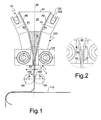
- the sheeter machine 10 comprises a container 20 substantially funnel-shaped and suitable to receive an alimentary dough 30 through an inlet opening 40.
- the container 20 is also equipped with an outlet opening 50 suitable to allow passage of the dough 30 in order to form a sheet dough.
- the outlet opening 50 is defined by the lower edges 61, 71 of a pair of walls 60, 70 of the container 20, that are in the form of flat plates opposite to each other and converging from the inlet opening 40.
- the compacting nip 100 has a transverse size smaller than the transverse size of the outlet opening 50 of the container 20, adapted to reduce the thickness of the dough coming out therefrom.
- the transverse size of the compacting nip 100 may be adjusted depending on production requirements and on the type of dough processed by varying the distance between the axes of the counter-rotating rollers.
- rollers 80, 90 are connected to a gear motor (not shown) that allows their rotation in the opposite directions, thus dragging the dough 30 through the compacting nip 100.
- the rollers 80, 90 are counter-rotating rollers.
- the direction of rotation of the counter-rotating rollers 80, 90 is shown by way of arrows.
- a conveyor belt 110 Downstream of the counter-rotating rollers 80, 90 a conveyor belt 110 is arranged, which collects the sheet dough produced and conveys it to a packaging unit or to further processing units.
- At least one of the converging walls 60, 70 of the container 20 is movably restrained to a frame (not shown) of the sheeter machine 10 through a kinematic chain suitable to allow a rotation-translation movement of the converging wall, the movement being provided by a drive, typically an electric motor.
- the rotational-translational movement of the at least one movable converging wall relative to the other one simultaneously results in a compression of the dough 30 and a movement thereof towards the outlet opening 50, whereby the dough 30 is subject to a progressive thickness reduction and comes from the container 20 in the form of a sheet.
- the processing of the dough 30 into a sheet dough is not exclusively performed by dragging by the counter-rotating rollers 80, 90, which generate high compression and shear stresses, but mainly occurs due to the rotational-translational movement of at least one of the converging walls 60, 70, i.e. by way of a compacting and progressively stretching movement.
- This configuration of the sheeter machine 10 deliberately resembles the manual movement of transformation of a dough into a sheet, which, as is known, allows to obtain a sheet dough having excellent organoleptic properties and high elasticity and compactness.
- the rotational speed of the counter-rotating rollers 80, 90 is adjusted so as to obtain a tangential velocity of the dough 30 at the compacting nip 100 that is substantially equal to the speed it has when coming out from the container 20. This results in a substantially straight flow between the outlet opening 50 and the compacting nip 100, as shown in Figure 1 .
- the converging walls 60, 70 of the container 20 have extensions 62, 72 substantially parallel to each other at their lower edges 61, 71.
- both converging walls 60, 70 are movably mounted on the frame of the sheeter machine 10, so that the compacting and dragging movement of the dough 30 is symmetrical.
- each kinematic chain 120 comprises an eccentric roller 121 and a pin 122 slidably restrained to a guide 123, these being respectively connected to an outer surface 63, 73 of the converging walls 60, 70.
- each eccentric roller 121 is connected to the respective movable wall 60, 70 proximate to the outlet opening 50, while the respective pins 122 and guides 123 are connected to the walls 60, 70 proximate to the inlet opening 40 of the container 20.
- pins and guides the rotation-translation movement provided by the kinematic chain may be obtained by using cranks, cams and in many other equivalent ways well-known to those skilled in the art.
- the kinematic chains associated with the converging walls 60, 70 of the container 20 may be advantageously synchronized with each other, so as to achieve a symmetrical compacting and dragging movement of the dough 30, as well as to balance the mechanical forces withstood by the frame of the sheeter machine 10.
- the inner surfaces 64, 74 of the converging walls 60, 70 are preferably rough or may be provided with a plurality of reliefs as, for example, textures, ridges and the like.
- the transverse size of the outlet opening 50 is preferably comprised between 5 and 6 mm.
- the sheeter machine 10 also comprises a control device arranged downstream of the outlet opening 50 proximate to the compacting nip 100 defined between the rollers 80, 90 and adapted to detect increases in the amount of dough 30 passing therebetween.
- the inventor has found that in order to minimize the build-up of dough at the compacting nip 100 it is necessary to increase the speed of rotation of the counter-rotating rollers 80, 90.
- the rotation speed of the counter-rotating rollers 80, 90 is temporarily increased whenever the amount of dough built up at the compacting nip 100 exceeds a predefined movement threshold 140 in the transverse direction T.
- the movement threshold 140 is of a linear type and comprises at least one straight line that extends in the longitudinal direction L of the sheeter machine 10 parallel to the compacting nip 100 is spaced away therefrom in the transverse direction T.
- the movement threshold 140 represents a maximum distance from the compacting nip 100 in the transverse direction T within which a movement of the flow of the dough 30 relative to a substantially straight flow direction between the outlet opening 50 and the compacting nip 100 can be tolerated.
- the control device comprises a pair of passage detectors 130 restrained to the frame of the sheeter machine 10 and arranged at the ends of at least one of the counter-rotating rollers 80, 90, the roller 80 in the illustrated embodiment.
- the passage detectors 130 are aligned in the longitudinal direction L parallel to the compacting nip 100 and are spaced therefrom in the transverse direction T, thus defining the movement threshold 140.
- the size of the movement threshold may vary depending on the type of dough to be processed and may e.g. be comprised between 8 and 15 mm.
- the movement threshold may advantageously comprise a pair of lines parallel to the compacting nip 100 and arranged on opposite sides thereof in the transverse direction T. This configuration allows to increase the reliability of the control device and to detect not only swelling of the dough, which is substantially symmetrical relative to a median plane M of the sheeter machine 10 in the transverse direction T, but its deviations in the same transverse direction T in one or the opposite way with respect to the straight flow path, which lies on the median plane M.
- control device may include two pairs of passage detectors 130 arranged on opposite sides of the compacting nip 100 in the transverse direction T.
- the passage detectors 130 are of a contactless type and in particular optical sensors.
- optical sensors those comprising optical fibers are preferred. These sensors in fact are extremely cheap and are not subj ect to oxidation problems. Optical fiber sensors are also compact, easy to install and insensitive to environmental factors such as, for example, humidity.
- optical sensors such as, for example, infrared sensors.
- the light beam emitted by the optical fibers is interrupted, thus causing the generation of an alarm signal on the basis of which the rotational speed of the counter-rotating rollers 80, 90 is increased.
- This has the effect of progressively restoring the linear flow condition of the mass of the dough 30 shown in Figure 4 , i.e. of bringing the flow within the limit of movement from the compacting nip 100 defined by the movement threshold 140.
- the rotational speed of the counter-rotating rollers 80, 90 is reduced to a nominal operation value, i.e. the value set under normal operating conditions of the sheeter machine 10.
- the generation of the alarm signal and the control of the rotational speed of the counter-rotating rollers 80, 90 as a function of this signal may be advantageously automatically controlled by a control system (not shown) of the sheeter machine 10 by way of a suitable control program stored therein.
- passage detectors 130 of a contact type e.g. comprising deformable members suitable to come into contact with the dough 30 when it swells or deviates from the straight flow path going beyond the movement threshold 140.
- the deformable members e.g. in the form of rods, might be associated with micro switches activated upon their movement.
Landscapes
- Life Sciences & Earth Sciences (AREA)
- Engineering & Computer Science (AREA)
- Food Science & Technology (AREA)
- Manufacturing And Processing Devices For Dough (AREA)
- Noodles (AREA)
Description
- The present invention relates to the field of processing alimentary doughs and in particular to a dough sheeter machine and a method of processing an alimentary dough to obtain a sheet dough.
- There are known sheeter machines for alimentary doughs, such as for the preparation of fresh pasta and desserts, comprising a container capable of receiving an alimentary dough, downstream of which one or more pairs of counter-rotating rollers are arranged, through which the dough is subject to a "rolling" action, i.e. a progressive reduction in thickness, thus allowing to obtain a sheet having a predetermined thickness.
- The transverse size of the nips defined between the counter-rotating rollers may be adjusted by increasing or decreasing the distance between their axes in order to obtain the desired thickness depending on the type of dough and sheet to be produced. For example, in the case of pasta, a thin sheet for "lasagne" or a thicker sheet for other types of pasta such as "tagliatelle" and "spaghetti".
- Sheeter machines are also known in which the container is provided with rollers adapted to allow a progressive reduction in the thickness of a dough. In this way the dough is transformed into a sheet directly in the container and the sheet coming out therefrom is collected on a conveyor belt.
- The European patent
EP 1455583 describes, for example, a sheeter machine comprising a container suitable to receive an alimentary dough and provided with a pair of longitudinal guiding elements opposite to each other and adapted to allow the passage of the dough and its progressive reduction in thickness. The guiding elements each comprise a plurality of kneading rollers and other rollers that during operation are operated in opposite directions of rotation in order to convey the dough from the inlet to the outlet of the container. - Dough sheeters machines are also known comprising both a container suitable to carry out kneading of a dough, and more generally its transformation into a sheet, and one or more pairs of counter-rotating rollers arranged downstream of the container. In this case the counter-rotating rollers arranged downstream of the container do not roll the dough, which comes out of the container already in a sheet form, but carry out a compacting and refining action in which the molecules of the dough are oriented and stretched, thus making the finished sheet uniform and compact.
-
US 6322345 discloses a sheeter machine according to the preamble of claim 1 and a corresponding method of processing an alimentary dough to obtain a sheet dough. - During the transformation into a sheet, the dough is subjected to compression stresses and in particular to high shear stresses, as well as to friction heating due to its passage through the kneading rollers. It has been observed that due to these problems the final sheet dough loses the elasticity, the homogeneity and the color of the original dough, resulting in a degradation of its organoleptic properties. It is believed that the degradation of the dough quality occurs not only during the kneading step, but also during the subsequent steps of thickness reduction through the counter-rotating rollers arranged downstream of the container.
- In fact, the amount of sheet dough coming out from the container and passing through the counter-rotating rollers arranged downstream thereof is not always constant. In particular, it has been noted that unpredictable increases in the amount of dough passing through the rollers result in its build-up upstream of the compacting nip defined between the counter-rotating rollers. This causes an increase in compressive stresses and particularly in shear stresses in the dough mass passing through the compacting nip and therefore, as in the kneading step, a loss of elasticity, homogeneity and color of the dough worsening its organoleptic properties.
- There is therefore a need to provide sheeter machines suitable to further improve the characteristics of elasticity, homogeneity and, more generally, the organoleptic properties of an alimentary sheet dough, which is the main object of the present invention.
- An idea of solution underlying the present invention is to adjust the rotation speed of the counter-rotating rollers arranged downstream of the container in order to prevent dough build-up whenever a larger amount of dough comes out from the container. In particular, the rotation speed of the counter-rotating rollers is temporarily increased so as to allow the eliminate amounts of dough in excess with respect to a nominal flow condition.
- In order to allow to adjust the rotational speed of the counter-rotating rollers, the sheeter machine according to the invention comprises a control device arranged between the outlet opening of the container and the counter-rotating rollers proximate to the compacting nip defined between them and suitable to detect movements of the dough transverse to the compacting nip beyond a predefined threshold, thus generating an alarm signal. Such movements are in fact the direct consequence of the build-up of dough at the compacting nip. The rotational speed of the counter-rotating rollers is regulated by a control signal as a function of the alarm signal.
- Thanks to these characteristics it is possible to maintain the flow of dough between the outlet opening of the container and the counter-rotating rollers in the ideal condition in which compressive stresses and in particular shear stresses are kept to a minimum compatibly with the sheeting process.
- The control device is preferably of a contactless type, e.g. comprising optical sensors. This allows to detect movements of the dough transverse to the compacting nip in a simple and reliable manner, while minimizing the problems of fouling and/or blocking caused by portions and/or fragments that are detached from the dough mass passing through the counter-rotating rollers.
- The use of a control device capable of minimizing the problems of dough build-up at the compacting nip may be advantageously combined with the use of a container equipped with a rotating-translating flat plates as described in Italian patent application
ITM120091322 - The combination with the control device allows to prosecute sheeting of the dough while minimizing compression and shear stresses and thus to obtain sheet doughs that have substantially the same organoleptic properties of the dough introduced into the container despite the mechanical actions to which the dough is subject along the sheeting path. The sheet dough produced has substantially the same characteristics of elasticity, homogeneity and color of the original dough, thus being in ideal conditions not only for a direct use in the preparation of lasagne, spaghetti and the like, but also for further processing operations necessary to the preparation of stuffed pasta such as e.g. "ravioli", "tortelli" and "tortellini".
- Further advantages and features of the sheeter machine and the sheeting method according to the present invention will be clear to those skilled in the art from the following detailed and non-limiting description of an embodiment thereof with reference to the attached drawings in which:
-
Figure 1 is a cross-sectional view schematically showing a sheeter machine according to the present invention; -
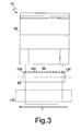
Figure 2 shows a detail II offigure 1 ; -
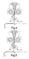
Figure 3 shows a lateral view of the machine offigure 1 ; and -
Figures 4 and 5 are cross-sectional views similar to that ofFigure 1 , showing two operation steps of the sheeter machine according to the invention. - Referring to
Figures 1 to 3 , thesheeter machine 10 according to the present invention comprises acontainer 20 substantially funnel-shaped and suitable to receive analimentary dough 30 through an inlet opening 40. Thecontainer 20 is also equipped with an outlet opening 50 suitable to allow passage of thedough 30 in order to form a sheet dough. - The outlet opening 50 is defined by the
lower edges 61, 71 of a pair ofwalls container 20, that are in the form of flat plates opposite to each other and converging from the inlet opening 40. - Downstream of the
container 20 there is at least one pair of motor drivenrollers sheeter machine 10 parallel to the outlet opening 50 and that are mutually spaced in a transverse direction T of thesheeter machine 10, perpendicular to the longitudinal direction L, so as to define between them a compactingnip 100 suitable to allow passage of thedough 30 coming out from thecontainer 20. - The compacting
nip 100 has a transverse size smaller than the transverse size of the outlet opening 50 of thecontainer 20, adapted to reduce the thickness of the dough coming out therefrom. The transverse size of the compactingnip 100 may be adjusted depending on production requirements and on the type of dough processed by varying the distance between the axes of the counter-rotating rollers. - The
rollers dough 30 through the compactingnip 100. In other words, therollers counter-rotating rollers - Downstream of the
counter-rotating rollers 80, 90 aconveyor belt 110 is arranged, which collects the sheet dough produced and conveys it to a packaging unit or to further processing units. - Preferably, at least one of the converging
walls container 20 is movably restrained to a frame (not shown) of thesheeter machine 10 through a kinematic chain suitable to allow a rotation-translation movement of the converging wall, the movement being provided by a drive, typically an electric motor. - The rotational-translational movement of the at least one movable converging wall relative to the other one simultaneously results in a compression of the
dough 30 and a movement thereof towards the outlet opening 50, whereby thedough 30 is subject to a progressive thickness reduction and comes from thecontainer 20 in the form of a sheet. - Therefore, the processing of the
dough 30 into a sheet dough is not exclusively performed by dragging by thecounter-rotating rollers walls sheeter machine 10 deliberately resembles the manual movement of transformation of a dough into a sheet, which, as is known, allows to obtain a sheet dough having excellent organoleptic properties and high elasticity and compactness. - The rotational speed of the
counter-rotating rollers dough 30 at the compactingnip 100 that is substantially equal to the speed it has when coming out from thecontainer 20. This results in a substantially straight flow between the outlet opening 50 and the compactingnip 100, as shown inFigure 1 . - In order to facilitate the processing of the
dough 30 into a sheet dough, theconverging walls container 20 haveextensions 62, 72 substantially parallel to each other at theirlower edges 61, 71. - Preferably, both
converging walls sheeter machine 10, so that the compacting and dragging movement of thedough 30 is symmetrical. - In the illustrated embodiment each
kinematic chain 120 comprises aneccentric roller 121 and apin 122 slidably restrained to aguide 123, these being respectively connected to anouter surface converging walls eccentric roller 121 is connected to the respectivemovable wall respective pins 122 andguides 123 are connected to thewalls container 20. - Alternatively to the use of eccentric rollers, pins and guides the rotation-translation movement provided by the kinematic chain may be obtained by using cranks, cams and in many other equivalent ways well-known to those skilled in the art.
- The kinematic chains associated with the converging
walls container 20 may be advantageously synchronized with each other, so as to achieve a symmetrical compacting and dragging movement of thedough 30, as well as to balance the mechanical forces withstood by the frame of thesheeter machine 10. - In order to increase the grip on the
dough 30 and therefore facilitate the dragging action inside thecontainer 20, theinner surfaces converging walls - In order to keep the properties of the
dough 30 introduced into thecontainer 20 as constant as possible, the transverse size of the outlet opening 50 is preferably comprised between 5 and 6 mm. - According to the present invention, the
sheeter machine 10 also comprises a control device arranged downstream of the outlet opening 50 proximate to the compactingnip 100 defined between therollers dough 30 passing therebetween. - On equal rotation speed of the
counter-rotating rollers dough 30 coming out from thecontainer 20 will cause a progressive build-up thereof at the compactingnip 100, thus interrupting its substantially straight flow. Thealimentary dough 30 tends in particular to swell in the transverse direction T, thus losing the thickness acquired when coming out from thecontainer 20. Consequently, the dough molecules passing through the compactingnip 100 are subjected to compression and shear stresses much higher than those of a normal operation condition, thus worsening the properties of the sheet dough produced, particularly in terms of elasticity, homogeneity and color. - The inventor has found that in order to minimize the build-up of dough at the compacting
nip 100 it is necessary to increase the speed of rotation of thecounter-rotating rollers - According to the invention, the rotation speed of the
counter-rotating rollers predefined movement threshold 140 in the transverse direction T. - The
movement threshold 140 is of a linear type and comprises at least one straight line that extends in the longitudinal direction L of thesheeter machine 10 parallel to the compacting nip 100 is spaced away therefrom in the transverse direction T. In other words, themovement threshold 140 represents a maximum distance from the compacting nip 100 in the transverse direction T within which a movement of the flow of thedough 30 relative to a substantially straight flow direction between theoutlet opening 50 and the compacting nip 100 can be tolerated. - To this aim, with particular reference to
Figure 3 , the control device comprises a pair ofpassage detectors 130 restrained to the frame of thesheeter machine 10 and arranged at the ends of at least one of thecounter-rotating rollers roller 80 in the illustrated embodiment. Thepassage detectors 130 are aligned in the longitudinal direction L parallel to the compacting nip 100 and are spaced therefrom in the transverse direction T, thus defining themovement threshold 140. - The size of the movement threshold may vary depending on the type of dough to be processed and may e.g. be comprised between 8 and 15 mm.
- The movement threshold may advantageously comprise a pair of lines parallel to the compacting nip 100 and arranged on opposite sides thereof in the transverse direction T. This configuration allows to increase the reliability of the control device and to detect not only swelling of the dough, which is substantially symmetrical relative to a median plane M of the
sheeter machine 10 in the transverse direction T, but its deviations in the same transverse direction T in one or the opposite way with respect to the straight flow path, which lies on the median plane M. - For this purpose the control device may include two pairs of
passage detectors 130 arranged on opposite sides of the compacting nip 100 in the transverse direction T. - According to an embodiment of the invention, the
passage detectors 130 are of a contactless type and in particular optical sensors. - Among the optical sensors, those comprising optical fibers are preferred. These sensors in fact are extremely cheap and are not subj ect to oxidation problems. Optical fiber sensors are also compact, easy to install and insensitive to environmental factors such as, for example, humidity.
- Alternatively, it is possible to use other types of optical sensors, such as, for example, infrared sensors.
- Referring to
Figure 4 , in a normal operating condition the flow of thedough 30 between theoutlet opening 50 and the compacting nip 100 is substantially straight, whereby thedough 30 does not cross themovement threshold 140 defined by thepassage detectors 130. - Referring to
Figure 5 , when an increase in the amount of dough coming out from thecontainer 20 occurs, as explained above thedough 30 moves, typically swells, in the transverse direction T, thus crossing themovement threshold 140. - When using optical fiber sensors, the light beam emitted by the optical fibers is interrupted, thus causing the generation of an alarm signal on the basis of which the rotational speed of the
counter-rotating rollers dough 30 shown inFigure 4 , i.e. of bringing the flow within the limit of movement from the compacting nip 100 defined by themovement threshold 140. In this condition, the rotational speed of thecounter-rotating rollers sheeter machine 10. - The generation of the alarm signal and the control of the rotational speed of the
counter-rotating rollers sheeter machine 10 by way of a suitable control program stored therein. - The embodiment of the invention herein described and illustrated is only an example susceptible of numerous variants. For example, it is possible to use
passage detectors 130 of a contact type, e.g. comprising deformable members suitable to come into contact with thedough 30 when it swells or deviates from the straight flow path going beyond themovement threshold 140. The deformable members, e.g. in the form of rods, might be associated with micro switches activated upon their movement.
Claims (11)
- A sheeter machine (10) for alimentary doughs, comprising a container (20) suitable to receive an alimentary dough (30) through an inlet opening (40) and provided with an outlet opening (50) for said dough (30), said sheeter machine (10) further comprising at least one pair of motor driven counter-rotating rollers (80, 90) arranged downstream of said outlet opening (50) and suitable to receive the dough (30) coming out from the container (20) in order to reduce its thickness through a compacting nip (100) defined between them in a transverse direction (T) of the sheeter machine (10), the sheeter machine (10) further comprising a control device arranged between the outlet opening (50) and said counter-rotating rollers (80, 90) proximate to said compacting nip (100) and adapted to detect increases in the amount of dough (30) passing therebetween, characterized in that said control device comprises at least one pair of passage detectors (130) arranged at the ends of at least one of the counter-rotating rollers (80, 90) in a longitudinal direction (L) of the sheeter machine (10), said passage detectors (130) being aligned in said longitudinal direction (L) parallel to the compacting nip (100) and being spaced therefrom in said transverse direction (T) thus defining a movement threshold (140).
- A sheeter machine (10) according to claim 1, wherein said passage detectors (130) are of a contactless type.
- A sheeter machine (10) according to claim 2, wherein said passage detectors (130) are optical sensors.
- A sheeter machine (10) according to claim 3, wherein said optical sensors comprise optical fibers.
- A sheeter machine (10) according to any one of claims 1 to 4, further comprising a control system capable of automatically controlling the rotational speed of the counter-rotating rollers (80, 90) as a function of an alarm signal generated by the passage detectors (130) of the control device.
- A sheeter machine (10) according to any one of claims 1 to 5, wherein the outlet opening (50) is defined by lower edges (61, 71) of a pair of walls (60, 70) of the container (20) opposite to each other and converging from said inlet opening (40).
- A sheeter machine (1) according to claim 6, wherein said converging walls (60, 70) are flat plates and wherein at least one of said flat plates is movably restrained to a frame of the sheeter machine (10) through a kinematic chain (120) suitable to provide it with a rotational-translational movement.
- A method of processing an alimentary dough to obtain a sheet dough, wherein an alimentary dough (30) is inserted into a container (20) of a sheeter machine (10) and comes out therefrom through an outlet opening (50), said alimentary dough (30) being dragged by at least one pair of motor driven counter-rotating rollers (80, 90) through compacting nip (100) defined between them in a transverse direction (T), said method further comprising the steps of:i. providing a control device between said outlet opening (50) and said counter-rotating rollers (80, 90), said control device comprising at least one pair of passage detectors (130) restrained to a frame of the sheeter machine (10) at the ends of at least one of the counter-rotating rollers (80, 90);ii. arranging said passage detectors (130) in a longitudinal direction (L) parallel to the compacting nip (100) and spaced therefrom in said transverse direction (T) so as to defme a threshold (140) of movement of the alimentary dough (30) from the compacting nip (100) in said transverse direction (T);iii. configuring the passage detectors (130) so as to generate an alarm signal when the alimentary dough (30) crosses the movement threshold (140);iv. generating an alarm signal upon detection of a movement of the alimentary dough (30) beyond said movement threshold (140);v. temporarily increasing the rotational speed of the counter-rotating rollers (80, 90) upon generation of said alarm signal; andvi. reducing the rotational speed of the counter-rotating rollers (80, 90) to a nominal operating value when the alimentary dough (30) returns within the movement limit of movement from the compacting nip (100) defined by the movement threshold (140).
- A sheet dough processing method according to claim 8, wherein said movement threshold (140) comprises at least one straight line that extends in the longitudinal direction (L) of the sheeter machine (10) parallel to the compacting nip (100), said line being spaced from the compacting nip (100) in the transverse direction (T).
- A sheet dough processing method according to claim 8 or 9, wherein detection of a movement of the alimentary dough beyond the movement threshold (140) is an optical detection.
- A sheet dough processing method according to any one of claims 8 to 11, wherein the alarm signal and the rotational speed of the counter-rotating rollers are controlled by a control system of the sheeter machine (10) by means of a control program stored therein.
Priority Applications (2)
| Application Number | Priority Date | Filing Date | Title |
|---|---|---|---|
| EP20110425298 EP2604119B1 (en) | 2011-12-13 | 2011-12-13 | Sheeter machine and method of making an alimentary sheet dough |
| ES11425298.4T ES2528440T3 (en) | 2011-12-13 | 2011-12-13 | Laminating machine and procedure for the manufacture of a sheet of pasta |
Applications Claiming Priority (1)
| Application Number | Priority Date | Filing Date | Title |
|---|---|---|---|
| EP20110425298 EP2604119B1 (en) | 2011-12-13 | 2011-12-13 | Sheeter machine and method of making an alimentary sheet dough |
Publications (2)
| Publication Number | Publication Date |
|---|---|
| EP2604119A1 EP2604119A1 (en) | 2013-06-19 |
| EP2604119B1 true EP2604119B1 (en) | 2014-10-22 |
Family
ID=45592143
Family Applications (1)
| Application Number | Title | Priority Date | Filing Date |
|---|---|---|---|
| EP20110425298 Not-in-force EP2604119B1 (en) | 2011-12-13 | 2011-12-13 | Sheeter machine and method of making an alimentary sheet dough |
Country Status (2)
| Country | Link |
|---|---|
| EP (1) | EP2604119B1 (en) |
| ES (1) | ES2528440T3 (en) |
Families Citing this family (1)
| Publication number | Priority date | Publication date | Assignee | Title |
|---|---|---|---|---|
| DE102016120042B4 (en) * | 2016-10-20 | 2021-04-29 | Fritsch Bakery Technologies GmbH & Co. KG | Device for, in particular continuous, gravimetric dosing and portioning of individual dough portions from a dough mass |
Family Cites Families (8)
| Publication number | Priority date | Publication date | Assignee | Title |
|---|---|---|---|---|
| DE1632344B2 (en) * | 1968-01-05 | 1976-05-20 | Debag Deutsche Backofenbau GmbH, 8000 München | DEVICE FOR PRODUCING A DOUGH STRIP AND OPERATING PROCEDURES FOR THIS DEVICE |
| JPH0697934B2 (en) * | 1990-01-16 | 1994-12-07 | レオン自動機株式会社 | Fabric spreading method and apparatus |
| JPH04152835A (en) * | 1990-02-16 | 1992-05-26 | Rheon Autom Mach Co Ltd | Roller for extending dough |
| US5225209A (en) * | 1990-05-12 | 1993-07-06 | Rheon Automatic Machinery Co., Ltd. | Apparatus for stretching dough |
| JP2558196B2 (en) * | 1991-12-05 | 1996-11-27 | レオン自動機株式会社 | Method and apparatus for supplying uniform continuous dough such as bread dough |
| US6322345B1 (en) * | 1993-07-14 | 2001-11-27 | Doge Food Processing Machinery S.R.L. | Apparatus for forming edible bakery paste |
| AT411564B (en) | 2001-12-17 | 2004-03-25 | Koenig Maschinen Gmbh | DEVICE FOR THE CONTINUOUS PRODUCTION OF A DOUGH BELT |
| IT1395357B1 (en) * | 2009-07-24 | 2012-09-14 | Chiaramello | DOUGH MACHINE |
-
2011
- 2011-12-13 EP EP20110425298 patent/EP2604119B1/en not_active Not-in-force
- 2011-12-13 ES ES11425298.4T patent/ES2528440T3/en active Active
Also Published As
| Publication number | Publication date |
|---|---|
| ES2528440T3 (en) | 2015-02-10 |
| EP2604119A1 (en) | 2013-06-19 |
Similar Documents
| Publication | Publication Date | Title |
|---|---|---|
| CA2205738C (en) | Method and apparatus for continuously and quantitatively supplying breaddough | |
| EP3166410B1 (en) | Method for producing elongate foodstuffs | |
| FI127162B (en) | Cutter for cutting oblong foods | |
| EP2604119B1 (en) | Sheeter machine and method of making an alimentary sheet dough | |
| CN207604432U (en) | A kind of auto-folder dough kneeding machine | |
| JP2018519848A (en) | Method and apparatus for forming baguettes, elongated breads, and elongated rolls | |
| US5686129A (en) | Calendering apparatus and method for rolling dough | |
| US10306896B2 (en) | Variable contoured rounding bar, device and method of using same | |
| JPS6362168B2 (en) | ||
| ITMI20070230A1 (en) | DEVICE AND PROCEDURE FOR THE PRODUCTION OF FILLED FOOD PRODUCTS | |
| EP2332412B1 (en) | Annexed pinning system for a dough moulder | |
| WO2015198292A1 (en) | Forming device for the production of pasta of elongated type and related method | |
| CA2926360A1 (en) | Device for forming a continuous strip of dough | |
| US10897912B2 (en) | Variable contoured rounding bar, device and method of using same | |
| EA047843B1 (en) | DEVICE FOR TRANSVERSE AND LONGITUDINAL STRETCHING OF A DOUGH LAYER (OPTIONS) | |
| EP2384628A1 (en) | Apparatus for processing dough, particularly of the bread baking type | |
| CN201630183U (en) | Adjustable cut-to-length sizes machine | |
| US20230043169A1 (en) | Noodle string cutting device, noodle manufacturing device, and noodle and instant noodle manufacturing method | |
| WO2010047667A2 (en) | A compact apparatus and process for fast and continuous production of baklava dough | |
| ITMI20111390A1 (en) | ADJUSTABLE GROUP FOR FOOD MIXING FORMATION | |
| CN223247414U (en) | Double-sided rolling machine | |
| CN202603497U (en) | Continuous rolling machine | |
| WO2015198293A1 (en) | Forming device for the production of pasta of elongated type and related method | |
| EP3462887B1 (en) | Device and method for processing dough | |
| US601221A (en) | bryce |
Legal Events
| Date | Code | Title | Description |
|---|---|---|---|
| PUAI | Public reference made under article 153(3) epc to a published international application that has entered the european phase |
Free format text: ORIGINAL CODE: 0009012 |
|
| AK | Designated contracting states |
Kind code of ref document: A1 Designated state(s): AL AT BE BG CH CY CZ DE DK EE ES FI FR GB GR HR HU IE IS IT LI LT LU LV MC MK MT NL NO PL PT RO RS SE SI SK SM TR |
|
| AX | Request for extension of the european patent |
Extension state: BA ME |
|
| 17P | Request for examination filed |
Effective date: 20131128 |
|
| RBV | Designated contracting states (corrected) |
Designated state(s): AL AT BE BG CH CY CZ DE DK EE ES FI FR GB GR HR HU IE IS IT LI LT LU LV MC MK MT NL NO PL PT RO RS SE SI SK SM TR |
|
| RIC1 | Information provided on ipc code assigned before grant |
Ipc: A21C 3/04 20060101AFI20140129BHEP |
|
| GRAP | Despatch of communication of intention to grant a patent |
Free format text: ORIGINAL CODE: EPIDOSNIGR1 |
|
| INTG | Intention to grant announced |
Effective date: 20140312 |
|
| GRAS | Grant fee paid |
Free format text: ORIGINAL CODE: EPIDOSNIGR3 |
|
| GRAA | (expected) grant |
Free format text: ORIGINAL CODE: 0009210 |
|
| AK | Designated contracting states |
Kind code of ref document: B1 Designated state(s): AL AT BE BG CH CY CZ DE DK EE ES FI FR GB GR HR HU IE IS IT LI LT LU LV MC MK MT NL NO PL PT RO RS SE SI SK SM TR |
|
| REG | Reference to a national code |
Ref country code: GB Ref legal event code: FG4D |
|
| REG | Reference to a national code |
Ref country code: CH Ref legal event code: EP |
|
| REG | Reference to a national code |
Ref country code: AT Ref legal event code: REF Ref document number: 692165 Country of ref document: AT Kind code of ref document: T Effective date: 20141115 |
|
| REG | Reference to a national code |
Ref country code: IE Ref legal event code: FG4D |
|
| REG | Reference to a national code |
Ref country code: DE Ref legal event code: R096 Ref document number: 602011010743 Country of ref document: DE Effective date: 20141204 |
|
| REG | Reference to a national code |
Ref country code: DE Ref legal event code: R082 Ref document number: 602011010743 Country of ref document: DE Representative=s name: SOCIETA ITALIANA BREVETTI S.P.A., IT |
|
| REG | Reference to a national code |
Ref country code: ES Ref legal event code: FG2A Ref document number: 2528440 Country of ref document: ES Kind code of ref document: T3 Effective date: 20150210 |
|
| RAP2 | Party data changed (patent owner data changed or rights of a patent transferred) |
Owner name: ARTECH SRL |
|
| RIN2 | Information on inventor provided after grant (corrected) |
Inventor name: CHIARAMELLO ANTONIO |
|
| REG | Reference to a national code |
Ref country code: NL Ref legal event code: VDEP Effective date: 20141022 |
|
| REG | Reference to a national code |
Ref country code: CH Ref legal event code: NV Representative=s name: RENTSCH PARTNER AG, CH Ref country code: CH Ref legal event code: PUE Owner name: ARTECH S.R.L., IT Free format text: FORMER OWNER: CHIARAMELLO, ANTONIO, IT |
|
| REG | Reference to a national code |
Ref country code: AT Ref legal event code: MK05 Ref document number: 692165 Country of ref document: AT Kind code of ref document: T Effective date: 20141022 |
|
| REG | Reference to a national code |
Ref country code: DE Ref legal event code: R081 Ref document number: 602011010743 Country of ref document: DE Owner name: ARTECH S.R.L., IT Free format text: FORMER OWNER: CHIARAMELLO, ANTONIO, CUNEO, IT Effective date: 20150205 Ref country code: DE Ref legal event code: R082 Ref document number: 602011010743 Country of ref document: DE Representative=s name: SOCIETA ITALIANA BREVETTI S.P.A., IT Effective date: 20150205 |
|
| REG | Reference to a national code |
Ref country code: LT Ref legal event code: MG4D Ref country code: GB Ref legal event code: 732E Free format text: REGISTERED BETWEEN 20150226 AND 20150304 |
|
| PG25 | Lapsed in a contracting state [announced via postgrant information from national office to epo] |
Ref country code: NO Free format text: LAPSE BECAUSE OF FAILURE TO SUBMIT A TRANSLATION OF THE DESCRIPTION OR TO PAY THE FEE WITHIN THE PRESCRIBED TIME-LIMIT Effective date: 20150122 Ref country code: FI Free format text: LAPSE BECAUSE OF FAILURE TO SUBMIT A TRANSLATION OF THE DESCRIPTION OR TO PAY THE FEE WITHIN THE PRESCRIBED TIME-LIMIT Effective date: 20141022 Ref country code: NL Free format text: LAPSE BECAUSE OF FAILURE TO SUBMIT A TRANSLATION OF THE DESCRIPTION OR TO PAY THE FEE WITHIN THE PRESCRIBED TIME-LIMIT Effective date: 20141022 Ref country code: IS Free format text: LAPSE BECAUSE OF FAILURE TO SUBMIT A TRANSLATION OF THE DESCRIPTION OR TO PAY THE FEE WITHIN THE PRESCRIBED TIME-LIMIT Effective date: 20150222 Ref country code: PT Free format text: LAPSE BECAUSE OF FAILURE TO SUBMIT A TRANSLATION OF THE DESCRIPTION OR TO PAY THE FEE WITHIN THE PRESCRIBED TIME-LIMIT Effective date: 20150223 Ref country code: LT Free format text: LAPSE BECAUSE OF FAILURE TO SUBMIT A TRANSLATION OF THE DESCRIPTION OR TO PAY THE FEE WITHIN THE PRESCRIBED TIME-LIMIT Effective date: 20141022 |
|
| PG25 | Lapsed in a contracting state [announced via postgrant information from national office to epo] |
Ref country code: LV Free format text: LAPSE BECAUSE OF FAILURE TO SUBMIT A TRANSLATION OF THE DESCRIPTION OR TO PAY THE FEE WITHIN THE PRESCRIBED TIME-LIMIT Effective date: 20141022 Ref country code: PL Free format text: LAPSE BECAUSE OF FAILURE TO SUBMIT A TRANSLATION OF THE DESCRIPTION OR TO PAY THE FEE WITHIN THE PRESCRIBED TIME-LIMIT Effective date: 20141022 Ref country code: HR Free format text: LAPSE BECAUSE OF FAILURE TO SUBMIT A TRANSLATION OF THE DESCRIPTION OR TO PAY THE FEE WITHIN THE PRESCRIBED TIME-LIMIT Effective date: 20141022 Ref country code: SE Free format text: LAPSE BECAUSE OF FAILURE TO SUBMIT A TRANSLATION OF THE DESCRIPTION OR TO PAY THE FEE WITHIN THE PRESCRIBED TIME-LIMIT Effective date: 20141022 Ref country code: RS Free format text: LAPSE BECAUSE OF FAILURE TO SUBMIT A TRANSLATION OF THE DESCRIPTION OR TO PAY THE FEE WITHIN THE PRESCRIBED TIME-LIMIT Effective date: 20141022 Ref country code: AT Free format text: LAPSE BECAUSE OF FAILURE TO SUBMIT A TRANSLATION OF THE DESCRIPTION OR TO PAY THE FEE WITHIN THE PRESCRIBED TIME-LIMIT Effective date: 20141022 Ref country code: GR Free format text: LAPSE BECAUSE OF FAILURE TO SUBMIT A TRANSLATION OF THE DESCRIPTION OR TO PAY THE FEE WITHIN THE PRESCRIBED TIME-LIMIT Effective date: 20150123 Ref country code: CY Free format text: LAPSE BECAUSE OF FAILURE TO SUBMIT A TRANSLATION OF THE DESCRIPTION OR TO PAY THE FEE WITHIN THE PRESCRIBED TIME-LIMIT Effective date: 20141022 |
|
| PG25 | Lapsed in a contracting state [announced via postgrant information from national office to epo] |
Ref country code: BE Free format text: LAPSE BECAUSE OF NON-PAYMENT OF DUE FEES Effective date: 20141231 |
|
| REG | Reference to a national code |
Ref country code: DE Ref legal event code: R097 Ref document number: 602011010743 Country of ref document: DE |
|
| PG25 | Lapsed in a contracting state [announced via postgrant information from national office to epo] |
Ref country code: LU Free format text: LAPSE BECAUSE OF FAILURE TO SUBMIT A TRANSLATION OF THE DESCRIPTION OR TO PAY THE FEE WITHIN THE PRESCRIBED TIME-LIMIT Effective date: 20141213 Ref country code: DK Free format text: LAPSE BECAUSE OF FAILURE TO SUBMIT A TRANSLATION OF THE DESCRIPTION OR TO PAY THE FEE WITHIN THE PRESCRIBED TIME-LIMIT Effective date: 20141022 Ref country code: SK Free format text: LAPSE BECAUSE OF FAILURE TO SUBMIT A TRANSLATION OF THE DESCRIPTION OR TO PAY THE FEE WITHIN THE PRESCRIBED TIME-LIMIT Effective date: 20141022 Ref country code: EE Free format text: LAPSE BECAUSE OF FAILURE TO SUBMIT A TRANSLATION OF THE DESCRIPTION OR TO PAY THE FEE WITHIN THE PRESCRIBED TIME-LIMIT Effective date: 20141022 Ref country code: RO Free format text: LAPSE BECAUSE OF FAILURE TO SUBMIT A TRANSLATION OF THE DESCRIPTION OR TO PAY THE FEE WITHIN THE PRESCRIBED TIME-LIMIT Effective date: 20141022 Ref country code: CZ Free format text: LAPSE BECAUSE OF FAILURE TO SUBMIT A TRANSLATION OF THE DESCRIPTION OR TO PAY THE FEE WITHIN THE PRESCRIBED TIME-LIMIT Effective date: 20141022 |
|
| PLBE | No opposition filed within time limit |
Free format text: ORIGINAL CODE: 0009261 |
|
| STAA | Information on the status of an ep patent application or granted ep patent |
Free format text: STATUS: NO OPPOSITION FILED WITHIN TIME LIMIT |
|
| REG | Reference to a national code |
Ref country code: IE Ref legal event code: MM4A |
|
| 26N | No opposition filed |
Effective date: 20150723 |
|
| PG25 | Lapsed in a contracting state [announced via postgrant information from national office to epo] |
Ref country code: IE Free format text: LAPSE BECAUSE OF NON-PAYMENT OF DUE FEES Effective date: 20141213 |
|
| PG25 | Lapsed in a contracting state [announced via postgrant information from national office to epo] |
Ref country code: SI Free format text: LAPSE BECAUSE OF FAILURE TO SUBMIT A TRANSLATION OF THE DESCRIPTION OR TO PAY THE FEE WITHIN THE PRESCRIBED TIME-LIMIT Effective date: 20141022 |
|
| PG25 | Lapsed in a contracting state [announced via postgrant information from national office to epo] |
Ref country code: SM Free format text: LAPSE BECAUSE OF FAILURE TO SUBMIT A TRANSLATION OF THE DESCRIPTION OR TO PAY THE FEE WITHIN THE PRESCRIBED TIME-LIMIT Effective date: 20141022 |
|
| PG25 | Lapsed in a contracting state [announced via postgrant information from national office to epo] |
Ref country code: MC Free format text: LAPSE BECAUSE OF FAILURE TO SUBMIT A TRANSLATION OF THE DESCRIPTION OR TO PAY THE FEE WITHIN THE PRESCRIBED TIME-LIMIT Effective date: 20141022 |
|
| REG | Reference to a national code |
Ref country code: FR Ref legal event code: PLFP Year of fee payment: 5 |
|
| PG25 | Lapsed in a contracting state [announced via postgrant information from national office to epo] |
Ref country code: BG Free format text: LAPSE BECAUSE OF FAILURE TO SUBMIT A TRANSLATION OF THE DESCRIPTION OR TO PAY THE FEE WITHIN THE PRESCRIBED TIME-LIMIT Effective date: 20141022 |
|
| PG25 | Lapsed in a contracting state [announced via postgrant information from national office to epo] |
Ref country code: HU Free format text: LAPSE BECAUSE OF FAILURE TO SUBMIT A TRANSLATION OF THE DESCRIPTION OR TO PAY THE FEE WITHIN THE PRESCRIBED TIME-LIMIT; INVALID AB INITIO Effective date: 20111213 Ref country code: TR Free format text: LAPSE BECAUSE OF FAILURE TO SUBMIT A TRANSLATION OF THE DESCRIPTION OR TO PAY THE FEE WITHIN THE PRESCRIBED TIME-LIMIT Effective date: 20141022 Ref country code: MT Free format text: LAPSE BECAUSE OF FAILURE TO SUBMIT A TRANSLATION OF THE DESCRIPTION OR TO PAY THE FEE WITHIN THE PRESCRIBED TIME-LIMIT Effective date: 20141022 |
|
| REG | Reference to a national code |
Ref country code: FR Ref legal event code: PLFP Year of fee payment: 6 |
|
| REG | Reference to a national code |
Ref country code: CH Ref legal event code: PCAR Free format text: NEW ADDRESS: BELLERIVESTRASSE 203 POSTFACH, 8034 ZUERICH (CH) |
|
| PG25 | Lapsed in a contracting state [announced via postgrant information from national office to epo] |
Ref country code: MK Free format text: LAPSE BECAUSE OF FAILURE TO SUBMIT A TRANSLATION OF THE DESCRIPTION OR TO PAY THE FEE WITHIN THE PRESCRIBED TIME-LIMIT Effective date: 20141022 |
|
| REG | Reference to a national code |
Ref country code: FR Ref legal event code: PLFP Year of fee payment: 7 |
|
| PG25 | Lapsed in a contracting state [announced via postgrant information from national office to epo] |
Ref country code: AL Free format text: LAPSE BECAUSE OF FAILURE TO SUBMIT A TRANSLATION OF THE DESCRIPTION OR TO PAY THE FEE WITHIN THE PRESCRIBED TIME-LIMIT Effective date: 20141022 |
|
| PGFP | Annual fee paid to national office [announced via postgrant information from national office to epo] |
Ref country code: ES Payment date: 20190621 Year of fee payment: 8 Ref country code: DE Payment date: 20190619 Year of fee payment: 8 Ref country code: IT Payment date: 20190624 Year of fee payment: 8 |
|
| PGFP | Annual fee paid to national office [announced via postgrant information from national office to epo] |
Ref country code: FR Payment date: 20190619 Year of fee payment: 8 |
|
| PGFP | Annual fee paid to national office [announced via postgrant information from national office to epo] |
Ref country code: CH Payment date: 20190619 Year of fee payment: 8 |
|
| PGFP | Annual fee paid to national office [announced via postgrant information from national office to epo] |
Ref country code: GB Payment date: 20190619 Year of fee payment: 8 |
|
| REG | Reference to a national code |
Ref country code: DE Ref legal event code: R119 Ref document number: 602011010743 Country of ref document: DE |
|
| REG | Reference to a national code |
Ref country code: CH Ref legal event code: PL |
|
| GBPC | Gb: european patent ceased through non-payment of renewal fee |
Effective date: 20191213 |
|
| PG25 | Lapsed in a contracting state [announced via postgrant information from national office to epo] |
Ref country code: FR Free format text: LAPSE BECAUSE OF NON-PAYMENT OF DUE FEES Effective date: 20191231 Ref country code: IT Free format text: LAPSE BECAUSE OF NON-PAYMENT OF DUE FEES Effective date: 20191213 Ref country code: GB Free format text: LAPSE BECAUSE OF NON-PAYMENT OF DUE FEES Effective date: 20191213 Ref country code: DE Free format text: LAPSE BECAUSE OF NON-PAYMENT OF DUE FEES Effective date: 20200701 |
|
| PG25 | Lapsed in a contracting state [announced via postgrant information from national office to epo] |
Ref country code: LI Free format text: LAPSE BECAUSE OF NON-PAYMENT OF DUE FEES Effective date: 20191231 Ref country code: CH Free format text: LAPSE BECAUSE OF NON-PAYMENT OF DUE FEES Effective date: 20191231 |
|
| REG | Reference to a national code |
Ref country code: ES Ref legal event code: FD2A Effective date: 20210601 |
|
| PG25 | Lapsed in a contracting state [announced via postgrant information from national office to epo] |
Ref country code: ES Free format text: LAPSE BECAUSE OF NON-PAYMENT OF DUE FEES Effective date: 20191214 |