EP2602889A2 - Wire fixing member and wire fixing method - Google Patents
Wire fixing member and wire fixing method Download PDFInfo
- Publication number
- EP2602889A2 EP2602889A2 EP12006994.3A EP12006994A EP2602889A2 EP 2602889 A2 EP2602889 A2 EP 2602889A2 EP 12006994 A EP12006994 A EP 12006994A EP 2602889 A2 EP2602889 A2 EP 2602889A2
- Authority
- EP
- European Patent Office
- Prior art keywords
- wire
- housing
- projecting portion
- housing projecting
- shield
- Prior art date
- Legal status (The legal status is an assumption and is not a legal conclusion. Google has not performed a legal analysis and makes no representation as to the accuracy of the status listed.)
- Granted
Links
- 238000000034 method Methods 0.000 title claims description 13
- 239000002390 adhesive tape Substances 0.000 claims abstract description 31
- 239000004020 conductor Substances 0.000 claims description 9
- 238000000576 coating method Methods 0.000 abstract description 13
- 238000009413 insulation Methods 0.000 abstract description 13
- UQMRAFJOBWOFNS-UHFFFAOYSA-N butyl 2-(2,4-dichlorophenoxy)acetate Chemical compound CCCCOC(=O)COC1=CC=C(Cl)C=C1Cl UQMRAFJOBWOFNS-UHFFFAOYSA-N 0.000 abstract description 11
- 239000011248 coating agent Substances 0.000 abstract description 9
- 230000002093 peripheral effect Effects 0.000 description 15
- 239000002184 metal Substances 0.000 description 6
- 238000006073 displacement reaction Methods 0.000 description 4
- 238000003780 insertion Methods 0.000 description 4
- 230000037431 insertion Effects 0.000 description 4
- 230000000149 penetrating effect Effects 0.000 description 2
- 229920005989 resin Polymers 0.000 description 2
- 239000011347 resin Substances 0.000 description 2
- 238000007789 sealing Methods 0.000 description 2
- 230000004308 accommodation Effects 0.000 description 1
- 239000012141 concentrate Substances 0.000 description 1
- 230000001419 dependent effect Effects 0.000 description 1
- 230000000694 effects Effects 0.000 description 1
- 238000005516 engineering process Methods 0.000 description 1
- 239000000463 material Substances 0.000 description 1
- 230000000717 retained effect Effects 0.000 description 1
- 229920003002 synthetic resin Polymers 0.000 description 1
- 239000000057 synthetic resin Substances 0.000 description 1
Images


Classifications
-
- H—ELECTRICITY
- H02—GENERATION; CONVERSION OR DISTRIBUTION OF ELECTRIC POWER
- H02G—INSTALLATION OF ELECTRIC CABLES OR LINES, OR OF COMBINED OPTICAL AND ELECTRIC CABLES OR LINES
- H02G3/00—Installations of electric cables or lines or protective tubing therefor in or on buildings, equivalent structures or vehicles
- H02G3/30—Installations of cables or lines on walls, floors or ceilings
- H02G3/32—Installations of cables or lines on walls, floors or ceilings using mounting clamps
Landscapes
- Engineering & Computer Science (AREA)
- Architecture (AREA)
- Civil Engineering (AREA)
- Structural Engineering (AREA)
- Details Of Connecting Devices For Male And Female Coupling (AREA)
- Shielding Devices Or Components To Electric Or Magnetic Fields (AREA)
Abstract
Description
- The present invention relates to a wire fixing member with a shield shell and to a wire fixing method.
- A wire fixing member disclosed in Japanese Unexamined Patent Publication No.
2002-134953 - In fixing the wires to the wire fixing member, the crimp fitting is first crimped and connected to insulation coatings of the wires and sandwiched from upper and lower sides by the wire holder, whereby the wire holder is fixed to the wires. Then, by accommodating the wire holder in the shield shell such that the wire holder does not come out, the wires are fixed to the wire fixing member.
- Since the crimp fitting made of metal is crimped and connected to the insulation coatings of the wires in the wire fixing member as described above, the crimp fitting crimped and connected to the wires may bite into the insulation coatings to break the insulation coatings and cores and the like inside may be damaged if the wires are strongly pulled or largely swung.
- The present invention was completed in view of the above situation and an object thereof is to fix a wire without damaging an insulation coating thereof.
- This object is solved according to the invention by the features of the independent claims. Particular embodiments of the invention are subject of the dependent claims.
- According to one aspect of the invention there is provided a wire fixing member to be fixed to a case housing of a device by fixing a shield shell to the case, comprising a housing to be at least partly held in the shield shell; at least one wire pulled out through the housing; at least one housing projecting portion located at a part of the housing where the wire is pulled out and formed to project substantially along the wire; and a covering member for integrally fixing the wire and the housing projecting portion by covering both the wire and the housing projecting portion and adhering to the wire and the housing projecting portion.
- According to the wire fixing member thus configured, if the wire is strongly pulled or largely swung, the covering member is caused to follow the wire and the wire and the housing projecting portion can be maintained in an integrally fixed state. By this, a state where the wire is fixed to the housing can be maintained without damaging an insulation coating of the wire.
- The following configurations are preferable as embodiments of the present invention.
- The housing projecting portion may be formed with at least one guide groove into which the wire at least partly is to be fitted.
- According to such a configuration, the wire can be easily arranged substantially along the housing projecting portion by being at least partly fitted into the guide groove, whereby operability in integrally fixing the wire and the housing projecting portion by the covering member can be improved.
- At least one flange which bites or engages into the covering member may be formed at or near a leading end part of the housing projecting portion in a projecting direction.
- According to such a configuration, the flange bites or engages into the covering member, whereby a fixing force of the covering member to the housing projecting portion can be enhanced.
- The covering member may be or comprise an adhesive tape which sticks to the wire and the housing projecting portion.
- According to such a configuration, the adhesive tape can stick to the wire and the housing projecting portion and the wire and the housing projecting portion can be more reliably integrally fixed as compared with a heat shrinking tube or the like.
- A dimension of the housing projecting portion in a projecting direction may be slightly larger than the outer diameter of the wire.
- A width of the covering member may be slightly larger than a projecting distance of the housing projecting portion.
- The covering member may be wound around the housing projecting portion and the wire in the width direction intersecting with an extending direction of the wire and/or may substantially cover from a base end of the housing projecting portion to a position somewhat before the leading end of the housing projecting portion.
- The shield shell may comprise at least one shield-connecting portion through which the wire can be passed, and the shield-connecting portion may be connected to the wire by means of a shield conductor and a connection member.
- The housing may comprise a resilient plug accommodating portion for at least partly accommodating a respective resilient plug fitted to the wire inside to provide fluidproofness.
- According to a further aspect of the invention, there is provided a method for fixing at least one wire to a wire fixing member to be fixed to a case housing of a device by fixing a shield shell to the case, comprising:
- providing a housing to be at least partly held in the shield shell;
- pulling out at least one wire through the housing such as to be located near and project substantially along at least one housing projecting portion of the housing; and
- integrally fixing the wire and the housing projecting portion by covering both the wire and the housing projecting portion with a covering member and adhering the covering member to the wire and the housing projecting portion.
- The following configurations are preferable as embodiments of the present invention.
- The wire fixing method may further comprise at least partly fitting the wire into at least one guide groove of the housing projecting portion.
- The wire fixing method may further comprise biting or engaging at least one flange formed at or near a leading end part of the housing projecting portion in a projecting direction into the covering member.
- The covering member may comprise an adhesive tape which sticks to the wire and the housing projecting portion.
- The covering member may be wound around the housing projecting portion and the wire in the width direction intersecting with an extending direction of the wire and/or substantially covers from a base end of the housing projecting portion to a position somewhat before the leading end of the housing projecting portion.
- The wire fixing method may further comprise passing the wire through at least one shield-connecting portion of the shield shell, and connecting the shield-connecting portion to the wire by means of a shield conductor and a connection member.
- According to the above, it is possible to fix a wire without damaging an insulation coating thereof.
- These and other objects, features and advantages of the present invention will become more apparent upon reading of the following detailed description of preferred embodiments and accompanying drawings. It should be understood that even though embodiments are separately described, single features thereof may be combined to additional embodiments.
-
FIG. 1 is a perspective view showing a state where wires are fixed to a wire fixing member, -
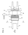
FIG. 2 is a plan view showing the state ofFIG. 1 , -
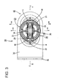
FIG. 3 is a front view showing the state ofFIG. 1 , -
FIG. 4 is a side view showing the state ofFIG. 1 , -
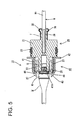
FIG. 5 is a section along A-A ofFIG. 3 , -
FIG. 6 is a section along B-B ofFIG. 3 , -
FIG. 7 is a section along C-C ofFIG. 3 , and -
FIG. 8 is a section along D-D ofFIG. 2 . - A particular embodiment of the present invention is described with reference to
FIGS. 1 to 8 . - As shown in
FIG. 1 , awire fixing member 10 in this embodiment includes ahousing 20 through which one or more wires W are to be passed substantially in forward and backward directions FBD and ashield shell 40 which is made of conductive material (such as metal) and to be mounted on (particularly a rear part of) thishousing 20. A part (particularly a front part) of thehousing 20 of thiswire fixing member 10 at least partly is fittable or insertable into an unillustrated (particularly substantially circular or rounded) mounting hole provided in a conductive (particularly metal) case, and theshield shell 40 and the case are shield-connected particularly by fixing theshield shell 40 to the case by at least one bolt (not shown). - The wire W is such that an unillustrated core is covered by an insulation coating W1, and an unillustrated terminal fitting is connected (particularly crimped and connected) to the core exposed by stripping the insulation coating W1 at or near an end of the wire W. The end of the wire W to which the terminal fitting is connected is to be pulled into the case through the mounting hole and connected to an unillustrated device housed in the case particularly by the terminal fitting being bolted to an unillustrated terminal block provided in the case.
- The
housing 20 is made e.g. of synthetic resin and the one or more wires W are to be passed through thehousing 20 substantially in forward and backward directions FBD as shown inFIGS. 6 and7 . Further, a part (particularly the front part) of thehousing 20 serves as afitting portion 21 at least partly fittable into the mounting hole and another part (particularly a rear part) thereof serves as a resilient or rubberplug accommodating portion 22 for at least partly accommodating one or more resilient plugs or rubber plugs G inside. - As shown in
FIG. 1 , thefitting portion 21 particularly has a substantially cylindrical or tubular shape and/or at least oneseal ring 23 is to be mounted on the outer peripheral surface of thefitting portion 21. When thefitting portion 21 at least partly is fitted into the mounting hole, this at least oneseal ring 23 is held in close contact with the outer peripheral surface of thefitting portion 21 and the inner peripheral surface of the mounting hole to seal between the outer peripheral surface of thefitting portion 21 and the inner peripheral surface of the mounting hole. - As shown in
FIG. 7 , one or more, particularly a pair ofwire insertion holes 24, through which the one or more respective wires W are to be inserted or passed in forward and backward directions FBD, are formed (particularly substantially side by side in a width direction in one or more stages) in thefitting portion 21, and an inner diameter thereof particularly is slightly larger than an outer diameter of the wires W. - Since only the wire(s) W is/are accommodated in the
fitting portion 21, an outer dimension of thefitting portion 21 can be made smaller in the width direction of thefitting portion 21 as compared with a fitting portion for accommodating one or more terminal fittings having a larger dimension in the width direction than the wire(s) W. - The resilient plug(s) G (particularly the substantially ring-shaped rubber plugs G) externally mounted on the wires W can be at least partly accommodated in the resilient plug accommodating portion 22 (particularly the rubber plug accommodating portion 22). When being at least partly accommodated into the resilient
plug accommodating portion 22, the resilient plug G (particularly the rubber plug G) comes into close contact with the outer peripheral surface of the wire W and the inner peripheral surface of the resilientplug accommodating portion 22, thereby sealing between the wire W and the resilientplug accommodating portion 22. - As shown in
FIG. 6 , a resilient plug presser 25 (particularly a rubber plug presser 25) to be engaged with the rear end surfaces of the resilient plugs G from behind for a locking purpose is assembled to thehousing 20, particularly at least partly into a rear end part of the resilientplug accommodating portion 22. A front end part of theresilient plug presser 25 is formed to be fittable into the resilientplug accommodating portion 22, and theresilient plug presser 25 is assembled into the resilientplug accommodating portion 22 by engaging at least onelocking projection 26 formed on (particularly the front end part of) theresilient plug presser 25 with the inner wall of the resilientplug accommodating portion 22. In this way, the one or more resilient plugs G are held not to come out of the resilientplug accommodating portion 22. - The
shield shell 40 particularly is formed such as by press-working and drawing an electrically conductive (particularly metal) plate material. Further, as shown inFIGS. 1 and2 , theshield shell 40 includes a shellmain portion 41 for at least partly accommodating the resilientplug accommodating portion 22 inside and a bulgingportion 42 bulging outward from the shellmain portion 41. - As shown in
FIGS. 1 and7 , the shellmain portion 41 particularly substantially is in the form of a receptacle which is open forward and the resilientplug accommodating portion 22 is or can be at least partly accommodated thereinto particularly substantially from front. One or more, particularly a pair of shield-connectingportions 43 are formed (particularly substantially side by side) in or on (particularly aback wall 41A of) the shellmain portion 41. The shield-connectingportion 43 particularly substantially is in the form of a cylindrical hole penetrating in forward and backward directions FBD and so formed that the wire W pulled out backward from the resilientplug accommodating portion 22 of thehousing 20 can be passed therethrough. A shield conductor (particularly a braided wire) H is mounted on the outer peripheral surface of the shield-connectingportion 43 and a connection member is connected (particularly a crimp ring R is crimped or bent or folded), whereby the shield conductor (particularly the braided wire) H is shield-connected and the wire W pulled out backward from the shield-connectingportion 43 is shielded by the shield conductor (braided wire) H. It should be understood that a shield conductor H different from a braided wire may be used according to a particular embodiment such as a conductive sheet or layer, a conductive film or the like. - As shown in
FIG. 5 , a pair of upper and lower locking holes 44 are formed in theback wall 41A of the shellmain portion 41. On the other hand, one or moreresilient locking pieces 27 insertable into the one or more respective locking holes 44 are provided on the resilientplug accommodating portion 22, particularly respectively provided on both upper and lower surfaces of the resilientplug accommodating portion 22. Theseresilient locking pieces 27 particularly substantially extend backward in a cantilever manner and are formed to be resiliently deformable in a vertical direction or a direction intersecting the forward and backward directions FBD. When the resilientplug accommodating portion 22 at least partly is accommodated into the shellmain portion 41, leading end part(s) of the resilient locking piece(s) 27 is/are respectively engaged with peripheral edge part(s) of the locking hole(s) 44 particularly substantially from behind. In this way, thehousing 20 is held and fixed to theshield shell 40. - As shown in
FIGS. 1 and2 , the bulgingportion 42 bulges out to extend along the outer surface of the case (in a direction at an angle different from 0° or 180°, preferably substantially perpendicular to an axial direction of the shellmain portion 41 and/or the forward and backward directions FBD) and particularly is circumferentially provided on a front end opening edge of the shellmain portion 41. Further, the bulgingportion 42 particularly substantially comes into surface contact with the outer surface of the case when thefitting portion 21 of thehousing 20 is fitted into the mounting hole. - A mounting
piece 45 extending forward (or at an angle different from 0° or 180°, preferably substantially perpendicular to the bulging portion 42) is formed on (particularly one lateral edge of) the bulgingportion 42. Abolt insertion hole 45A substantially penetrating in a plate thickness direction particularly is formed in the mountingpiece 45, and theshield shell 40 is held and fixed to the case and shield-connected particularly by inserting an unillustrated bolt into thebolt insertion hole 45A and screwing the bolt into the case. - As shown in
FIGS. 1 to 4 , ahousing projecting portion 28 projecting forward (or along the forward and backward directions FBD) is formed on (particularly the front surface of) thefitting portion 21, and thishousing projecting portion 28 and the one or more (e.g. two) wires W pulled out forward from thefitting portion 21 are tied together by at least one adhesive tape T, thereby being integrally fixed. - Specifically, as shown in
FIG. 7 , thehousing projecting portion 28 is arranged adjacent to the one or more wires W (particularly at least partly between the two wires W) pulled out forward from the front end surface of thefitting portion 21 and/or substantially extends straight along the one or more (e.g. two) wires W. As shown inFIGS. 3 and8 , one or more, particularly a pair ofguide grooves 29 into which the one or more respective wires W arranged adjacent to (particularly at the opposite sides of) thehousing projecting portion 28 are to be fitted are formed on (particularly substantially opposite widthwise end parts of) thehousing projecting portion 28. These one or more (particularly pair of) guidegrooves 29 particularly are formed to substantially have a concave cross-section recessed inwardly in the width direction, and/or particularly extend from the position of the front end surface of thefitting portion 21 to the front end position of thehousing projecting portion 28. The wire(s) W is/are respectively fitted into the guide groove(s) 29 in the width direction, whereby the wire(s) W can be arranged along thehousing projecting portion 28 - A dimension of the
housing projecting portion 28 in the vertical direction (projecting direction) is slightly larger than the outer diameter of the wire(s) W. In a state where the wire(s) W is/are fitted in the (particularly both) guide groove(s) 29, an outer peripheral shape formed by the upper and lower surfaces of thehousing projecting portion 28 and the outer peripheral surface(s) of the (both) wire(s) W located adjacent to (particularly substantially on the widthwise outer sides) is set to be a substantially elliptical shape long in a lateral direction (or a direction at an angle different from 0° or 180°, preferably substantially perpendicular to the forward and backward directions FBD). - Further, as shown in
FIG. 5 , one or more, particularly a pair of vertically bulgingflanges 30 are formed on or near a leading end part (front end part) of thehousing projecting portion 28. - The adhesive tape T particularly is made of resin and/or the width thereof is slightly larger than a projecting distance of the
housing projecting portion 28 as shown inFIG. 7 . Further, as shown inFIGS. 2 ,4 and5 , the adhesive tape T is to be wound around thehousing projecting portion 28 and the wire(s) W in the width direction intersecting with an extending direction of the wire(s) W with the wire(s) W respectively at least partly fitted in the guide groove(s) 29 of thehousing projecting portion 28, and/or particularly substantially covers from the base end of thehousing projecting portion 28 to a position somewhat before the leading end of thehousing projecting portion 28. Specifically, as shown inFIGS. 3 and8 , the wound adhesive tape T particularly has a substantially elliptical cross-sectional shape and reliably and closely sticks to the upper and lower surfaces of thehousing projecting portion 28 and the outer peripheral surfaces of the widthwise outer sides of the both wires W. In this way, the one or more (e.g. two) wires W and thehousing projecting portion 28 are integrally fixed. - Further, if the wire W is pulled forward or backward or swung in the width direction in a state where the one or more (e.g. two) wires W and the
housing projecting portion 28 are fixed, the adhesive tape T follows the wire W while integrally fixing the (both) wire(s) W and thehousing projecting portion 28, whereby the state where the (both) wire(s) W is/are fixed to thehousing projecting portion 28 can be maintained. In this way, a state where the wire(s) W is/are fixed to thehousing 20 can be maintained while avoiding the breakage of the insulation coating(s) W1 of the wire(s) W. - Further, since the adhesive tape T particularly sticks to the wire(s) W and the
housing projecting portion 28, the wire(s) W and thehousing projecting portion 28 can be more reliably integrally fixed. This can further suppress displacements of the wire(s) W from thehousing projecting portion 28 in forward and backward directions FBD as compared with the case where the wire W and the housing projecting portion are fixed by a heat shrinking tube or the like. - Further, when the
housing projecting portion 28 and the one or more (particularly both) wires W particularly are tied together by the adhesive tape T, the one or more (particularly pair of)flanges 30 of thehousing projecting portion 28 laterally or vertically bite into the adhesive tape T, whereby a front end part of the adhesive tape T laterally or vertically bulges. Specifically, a fixing force of the adhesive tape T to thehousing projecting portion 28 can be enhanced. This can suppress a forward or backward displacement of the adhesive tape T from thehousing projecting portion 28 even if the wire W is strongly pulled forward or backward. Consequently, forward and backward displacements of the wire(s) W from thehousing 20 can be suppressed. - This embodiment is configured as described above. Next, an example of a method for fixing the wires W to the
wire fixing member 10 is briefly described and functions and effects thereof are described. - First, the one or more (e.g. two) wires W each having the resilient plug G (particularly the rubber plug G) externally mounted and the
housing 20 are prepared, and the wire(s) W is/are inserted into the resilient plug accommodation portion 22 (particularly the rubber plug accommodating portion 22) and pulled out forward from the wire insertion hole(s) 24 of thefitting portion 21. - Then, the resilient plug(s) G is/are at least partly inserted into the resilient
plug accommodating portion 22 and the resilient plug presser 25 (particularly the rubber plug presser 25) particularly is further assembled into the resilientplug accommodating portion 22 behind or adjacent to the resilient plugs G. In this way, sealing is provided between the outer peripheral surface(s) of the wire(s) W and the inner peripheral surface of the resilientplug accommodating portion 22 by the resilient plugs G and the resilient plugs G particularly are retained by theresilient plug presser 25. Further, the one or more terminal fittings are connected (particularly crimped and connected) to one or more ends of the wire(s) W pulled out forward a specified (predetermined or predeterminable) distance from thefitting portion 21. - Subsequently, the one or more (e.g. two) wires W pulled out from the front surface of the
fitting portion 21 at least partly are fitted into the one or morerespective guide grooves 29 and/or substantially arranged along the (particularly substantially opposite end parts of) thehousing projecting portion 28. Then, the adhesive tape T is wound around thehousing projecting portion 28 and the one or more (e.g. two) wires W at least partly several times. At this time, since the one or more (both) wires W are guided by the respective guide groove(s) 29, the wire(s) W can easily substantially extend along (particularly the opposite end parts of) thehousing projecting portion 28 as compared with the case where they are not guided. In this way, operability in integrally fixing thehousing projecting portion 28 and the wires W by the adhesive tape T can be improved. - The adhesive tape T adheres to the lateral (upper and lower) surfaces of the
housing projecting portion 28 and the outer peripheral surface(s) of the widthwise outer side(s) of the one or more (e.g. two) wires W and at least partly covers thehousing projecting portion 28 and the (two) wire(s) W, whereby thehousing projecting portion 28 and the (two) wire(s) W are integrally fixed. Further, at or near the front end part of the adhesive tape T, the flange(s) 30 of thehousing projecting portion 28 particularly bite(s) and/or engage(s) into the adhesive tape T and a fixing force of the adhesive tape T to thehousing projecting portion 28 can be further enhanced. In this way, the one or more (e.g. two) wires W can be reliably fixed to thehousing 20. - Since the wire(s) W particularly is/are pulled out from both front and rear sides in the
wire fixing member 10 through which the wire(s) W particularly substantially is/are passed in forward and backward directions FBD as in this embodiment, the wire(s) W may be strongly pulled in forward and backward directions FBD and/or largely swung in the width direction in fixing thewire fixing member 10 to the case or fixing the terminal fitting(s) to the terminal block. In such a case, a stress particularly concentrates on a part where the wire(s) W is/are fixed. However, since the wire(s) W particularly is/are fixed to thehousing projecting portion 28 by the adhesive tape T made of resin according to this embodiment, the adhesive tape T follows the wire(s) W and the wire(s) W and thehousing projecting portion 28 are maintained in an integrally fixed state. Thus, the state where the wire(s) W is/are fixed to thehousing 20 can be maintained while avoiding a situation where the insulation coating(s) is/are damaged e.g. by a metal crimp member as with the conventional technology. - Further, since the one or
more flanges 30 particularly bite into the adhesive tape T wound around thehousing projecting portion 28 according to this embodiment, the fixing force of the adhesive tape T to thehousing projecting portion 28 can be enhanced and/or displacements of the adhesive tape T from thehousing projecting portion 28 in forward and backward directions FBD can be suppressed or significantly reduced. Thus, the state where the wires W are fixed to thehousing 20 can be more reliably maintained. - Accordingly, to fix a wire without damaging an insulation coating thereof., a
wire fixing member 10 to be fixed to an unillustrated case housing of a device by fixing ashield shell 40 to the case includes ahousing 20 to be held in theshield shell 40, one or more wires W pulled out through thehousing 20, ahousing projecting portion 28 located at a part of thehousing 20 where the one or more wires W are pulled out and formed to substantially project along the wires W, and an adhesive tape T for integrally fixing the wire(s) W and thehousing projecting portion 28 by covering both the wire(s) W and thehousing projecting portion 28 and adhering to the wire(s) W and thehousing projecting portion 28. - The present invention is not limited to the above described and illustrated embodiment. For example, the following embodiments are also included in the technical scope of the present invention.
- (1) Although the two wires W are passed through the
housing 20 in the above embodiment, the present invention is not limited to such a mode and, for example, a housing may be so configured that one, three or four or more wires are passed therethrough. - (2) Although the
wire fixing member 10 is of a fluidproof waterproof type including the resilient plugs G (particularly the rubber plugs G) and/or theseal ring 23 in the above embodiment, the present invention is not limited to such a mode and, for example, may be applied to a non-fluidproof or non-waterproof wire fixing member. - (3) Although a covering member is the adhesive tape T in the above embodiment, the present invention is not limited to such a mode and, for example, the covering member may be a heat shrinking tube.
-
- 10: wire fixing member
- 20: housing
- 28: housing projecting portion
- 29: guide groove
- 30: flange
- 40: shield shell
- T: adhesive tape (covering member)
- W: wire
Claims (15)
- A wire fixing member (10) to be fixed to a case housing of a device by fixing a shield shell (40) to the case, comprising:a housing (20) to be at least partly held in the shield shell (40);at least one wire (W) pulled out through the housing (20);at least one housing projecting portion (28) located at a part of the housing (20) where the wire (W) is pulled out and formed to project substantially along the wire (W); anda covering member (T) for integrally fixing the wire (W) and the housing projecting portion (28) by covering both the wire (W) and the housing projecting portion (28) and adhering to the wire (W) and the housing projecting portion (28).
- A wire fixing member according to claim 1, wherein the housing projecting portion (28) is formed with at least one guide groove (29) into which the wire (W) at least partly is to be fitted.
- A wire fixing member according to any one of the preceding claims, wherein at least one flange (30) which bites or engages into the covering member (T) is formed at or near a leading end part of the housing projecting portion (28) in a projecting direction.
- A wire fixing member according to any one of the preceding claims, wherein the covering member (T) comprises an adhesive tape (T) which sticks to the wire (W) and the housing projecting portion (28).
- A wire fixing member according to any one of the preceding claims, wherein a dimension of the housing projecting portion (28) in a projecting direction is slightly larger than the outer diameter of the wire (W).
- A wire fixing member according to any one of the preceding claims, wherein a width of the covering member (T) is slightly larger than a projecting distance of the housing projecting portion (28).
- A wire fixing member according to any one of the preceding claims, wherein the covering member (T) is to be wound around the housing projecting portion (28) and the wire (W) in the width direction intersecting with an extending direction of the wire (W) and/or substantially covers from a base end of the housing projecting portion (28) to a position somewhat before the leading end of the housing projecting portion (28).
- A wire fixing member according to any one of the preceding claims, wherein the shield shell (40) comprises at least one shield-connecting portion (43) through which the wire (W) can be passed, and wherein the shield-connecting portion (43) is to be connected to the wire (W) by means of a shield conductor (H) and a connection member (R).
- A wire fixing member according to any one of the preceding claims, wherein the housing (20) comprises a resilient plug accommodating portion (22) for at least partly accommodating a respective resilient plug (G) fitted to the wire (W) inside to provide fluidproofness.
- A method for fixing at least one wire (W) to a wire fixing member (10) to be fixed to a case housing of a device by fixing a shield shell (40) to the case, comprising:providing a housing (20) to be at least partly held in the shield shell (40);pulling out at least one wire (W) through the housing (20) such as to be located near and project substantially along at least one housing projecting portion (28) of the housing (20); andintegrally fixing the wire (W) and the housing projecting portion (28) by covering both the wire (W) and the housing projecting portion (28) with a covering member (T) and adhering the covering member (T) to the wire (W) and the housing projecting portion (28).
- A wire fixing method according to claim 10, further comprising at least partly fitting the wire (W) into at least one guide groove (29) of the housing projecting portion (28).
- A wire fixing method according to claim 10 or 11, further comprising biting or engaging at least one flange (30) formed at or near a leading end part of the housing projecting portion (28) in a projecting direction into the covering member (T).
- A wire fixing method according to any one of the preceding claims 10 to 12, wherein the covering member (T) comprises an adhesive tape (T) which sticks to the wire (W) and the housing projecting portion (28).
- A wire fixing method according to any one of the preceding claims 10 to 13, wherein the covering member (T) is wound around the housing projecting portion (28) and the wire (W) in the width direction intersecting with an extending direction of the wire (W) and/or substantially covers from a base end of the housing projecting portion (28) to a position somewhat before the leading end of the housing projecting portion (28).
- A wire fixing method according to any one of the preceding claims 10 to 14, further comprising passing the wire (W) through at least one shield-connecting portion (43) of the shield shell (40), and connecting the shield-connecting portion (43) to the wire (W) by means of a shield conductor (H) and a connection member (R).
Applications Claiming Priority (1)
| Application Number | Priority Date | Filing Date | Title |
|---|---|---|---|
| JP2011265544A JP5769024B2 (en) | 2011-12-05 | 2011-12-05 | Wire fixing member |
Publications (3)
| Publication Number | Publication Date |
|---|---|
| EP2602889A2 true EP2602889A2 (en) | 2013-06-12 |
| EP2602889A3 EP2602889A3 (en) | 2014-03-05 |
| EP2602889B1 EP2602889B1 (en) | 2015-03-25 |
Family
ID=47137425
Family Applications (1)
| Application Number | Title | Priority Date | Filing Date |
|---|---|---|---|
| EP12006994.3A Active EP2602889B1 (en) | 2011-12-05 | 2012-10-09 | Wire fixing member and wire fixing method |
Country Status (4)
| Country | Link |
|---|---|
| US (1) | US9203225B2 (en) |
| EP (1) | EP2602889B1 (en) |
| JP (1) | JP5769024B2 (en) |
| CN (1) | CN103140098B (en) |
Families Citing this family (2)
| Publication number | Priority date | Publication date | Assignee | Title |
|---|---|---|---|---|
| CN103767555A (en) * | 2014-01-24 | 2014-05-07 | 广东福尔电子有限公司 | Heat insulation plate of electric rice cooker |
| JP6229699B2 (en) * | 2015-08-31 | 2017-11-15 | 住友電装株式会社 | Shield conductive path |
Citations (1)
| Publication number | Priority date | Publication date | Assignee | Title |
|---|---|---|---|---|
| JP2002134953A (en) | 2000-10-20 | 2002-05-10 | Auto Network Gijutsu Kenkyusho:Kk | Structure and method for connecting electronic unit to shield cable |
Family Cites Families (10)
| Publication number | Priority date | Publication date | Assignee | Title |
|---|---|---|---|---|
| DE3173057D1 (en) * | 1981-02-11 | 1986-01-09 | Siemens Ag | Cable sleeve with a longitudinally split sleeve tube of shrinkable material |
| US5545854A (en) * | 1993-12-29 | 1996-08-13 | Yazaki Corporation | Grommet for wire sealing |
| US6595789B2 (en) | 2000-10-20 | 2003-07-22 | Autonetworks Technologies, Ltd. | Electronic unit, shield cable connecting structure, connecting method, wires waterproof-connecting structure, and method |
| US6660937B1 (en) * | 2002-11-07 | 2003-12-09 | Yazaki North America | Grommet for automotive wiring harness |
| JP5102443B2 (en) * | 2005-10-18 | 2012-12-19 | 矢崎総業株式会社 | Wire harness side shield connector |
| US7407331B2 (en) * | 2006-12-11 | 2008-08-05 | Fujikura Ltd. | Optical branching module and optical cable boot |
| JP5528007B2 (en) * | 2009-05-13 | 2014-06-25 | 矢崎総業株式会社 | Shielded wire fixing structure and fixing method |
| JP2011090842A (en) * | 2009-10-21 | 2011-05-06 | Yazaki Corp | Connector |
| JP5477026B2 (en) * | 2010-02-08 | 2014-04-23 | 住友電装株式会社 | connector |
| JP2011175775A (en) * | 2010-02-23 | 2011-09-08 | Sumitomo Wiring Syst Ltd | Connector device |
-
2011
- 2011-12-05 JP JP2011265544A patent/JP5769024B2/en active Active
-
2012
- 2012-10-09 EP EP12006994.3A patent/EP2602889B1/en active Active
- 2012-10-22 US US13/656,810 patent/US9203225B2/en active Active
- 2012-11-28 CN CN201210494884.1A patent/CN103140098B/en active Active
Patent Citations (1)
| Publication number | Priority date | Publication date | Assignee | Title |
|---|---|---|---|---|
| JP2002134953A (en) | 2000-10-20 | 2002-05-10 | Auto Network Gijutsu Kenkyusho:Kk | Structure and method for connecting electronic unit to shield cable |
Also Published As
| Publication number | Publication date |
|---|---|
| US20130140075A1 (en) | 2013-06-06 |
| US9203225B2 (en) | 2015-12-01 |
| CN103140098A (en) | 2013-06-05 |
| JP2013118120A (en) | 2013-06-13 |
| CN103140098B (en) | 2016-05-18 |
| JP5769024B2 (en) | 2015-08-26 |
| EP2602889B1 (en) | 2015-03-25 |
| EP2602889A3 (en) | 2014-03-05 |
Similar Documents
| Publication | Publication Date | Title |
|---|---|---|
| EP2610975B1 (en) | Unit comprising a wire fixing member and method of assembling it | |
| US9472901B2 (en) | Shield connector structure | |
| US6200162B1 (en) | Shielding terminal | |
| EP2833488A1 (en) | Structure for connecting braided shield wiring and method for manufacturing shield-wire harness | |
| US20120100753A1 (en) | L-shaped connector | |
| US20140209377A1 (en) | Connector structure | |
| JP2010268562A (en) | Structure of fixing shield cable and method for fixing the same | |
| US11799247B2 (en) | Connector, and connector structure including inner conductor and outer conductor | |
| JP4314589B2 (en) | Multipole coaxial connector | |
| JP2009021136A (en) | Waterproof connector | |
| US20220077635A1 (en) | Connector, and connector structure | |
| US8263865B2 (en) | Wire connection unit | |
| JP2011170996A (en) | Terminal fitting with waterproof function and waterproof connector | |
| EP2768088A1 (en) | Shield connector | |
| EP2602889A2 (en) | Wire fixing member and wire fixing method | |
| JP5191822B2 (en) | Shield connector | |
| JP5359321B2 (en) | Grounding wiring material, joint connector used therefor, and wire harness incorporating the grounding wiring material | |
| JP6553872B2 (en) | Rubber stopper for waterproof connector and waterproof connector | |
| JP6048327B2 (en) | connector | |
| JP2011060426A (en) | Connector | |
| JP4457862B2 (en) | connector | |
| JP2006244816A (en) | Mounting structure of terminal fitting to shielded wire | |
| JP2004158376A (en) | Shielded connector | |
| JP2019220248A (en) | Waterproof structure for multicore wire | |
| JP2007311216A (en) | Connector |
Legal Events
| Date | Code | Title | Description |
|---|---|---|---|
| PUAI | Public reference made under article 153(3) epc to a published international application that has entered the european phase |
Free format text: ORIGINAL CODE: 0009012 |
|
| AK | Designated contracting states |
Kind code of ref document: A2 Designated state(s): AL AT BE BG CH CY CZ DE DK EE ES FI FR GB GR HR HU IE IS IT LI LT LU LV MC MK MT NL NO PL PT RO RS SE SI SK SM TR |
|
| AX | Request for extension of the european patent |
Extension state: BA ME |
|
| PUAL | Search report despatched |
Free format text: ORIGINAL CODE: 0009013 |
|
| AK | Designated contracting states |
Kind code of ref document: A3 Designated state(s): AL AT BE BG CH CY CZ DE DK EE ES FI FR GB GR HR HU IE IS IT LI LT LU LV MC MK MT NL NO PL PT RO RS SE SI SK SM TR |
|
| AX | Request for extension of the european patent |
Extension state: BA ME |
|
| RIC1 | Information provided on ipc code assigned before grant |
Ipc: H02G 3/32 20060101AFI20140124BHEP |
|
| 17P | Request for examination filed |
Effective date: 20140828 |
|
| RBV | Designated contracting states (corrected) |
Designated state(s): AL AT BE BG CH CY CZ DE DK EE ES FI FR GB GR HR HU IE IS IT LI LT LU LV MC MK MT NL NO PL PT RO RS SE SI SK SM TR |
|
| GRAP | Despatch of communication of intention to grant a patent |
Free format text: ORIGINAL CODE: EPIDOSNIGR1 |
|
| INTG | Intention to grant announced |
Effective date: 20141028 |
|
| GRAS | Grant fee paid |
Free format text: ORIGINAL CODE: EPIDOSNIGR3 |
|
| GRAA | (expected) grant |
Free format text: ORIGINAL CODE: 0009210 |
|
| AK | Designated contracting states |
Kind code of ref document: B1 Designated state(s): AL AT BE BG CH CY CZ DE DK EE ES FI FR GB GR HR HU IE IS IT LI LT LU LV MC MK MT NL NO PL PT RO RS SE SI SK SM TR |
|
| REG | Reference to a national code |
Ref country code: GB Ref legal event code: FG4D |
|
| REG | Reference to a national code |
Ref country code: CH Ref legal event code: EP |
|
| REG | Reference to a national code |
Ref country code: IE Ref legal event code: FG4D |
|
| REG | Reference to a national code |
Ref country code: DE Ref legal event code: R096 Ref document number: 602012006078 Country of ref document: DE Effective date: 20150507 |
|
| REG | Reference to a national code |
Ref country code: AT Ref legal event code: REF Ref document number: 718380 Country of ref document: AT Kind code of ref document: T Effective date: 20150515 |
|
| PG25 | Lapsed in a contracting state [announced via postgrant information from national office to epo] |
Ref country code: HR Free format text: LAPSE BECAUSE OF FAILURE TO SUBMIT A TRANSLATION OF THE DESCRIPTION OR TO PAY THE FEE WITHIN THE PRESCRIBED TIME-LIMIT Effective date: 20150325 Ref country code: LT Free format text: LAPSE BECAUSE OF FAILURE TO SUBMIT A TRANSLATION OF THE DESCRIPTION OR TO PAY THE FEE WITHIN THE PRESCRIBED TIME-LIMIT Effective date: 20150325 Ref country code: FI Free format text: LAPSE BECAUSE OF FAILURE TO SUBMIT A TRANSLATION OF THE DESCRIPTION OR TO PAY THE FEE WITHIN THE PRESCRIBED TIME-LIMIT Effective date: 20150325 Ref country code: SE Free format text: LAPSE BECAUSE OF FAILURE TO SUBMIT A TRANSLATION OF THE DESCRIPTION OR TO PAY THE FEE WITHIN THE PRESCRIBED TIME-LIMIT Effective date: 20150325 |
|
| REG | Reference to a national code |
Ref country code: AT Ref legal event code: MK05 Ref document number: 718380 Country of ref document: AT Kind code of ref document: T Effective date: 20150325 |
|
| REG | Reference to a national code |
Ref country code: LT Ref legal event code: MG4D |
|
| PG25 | Lapsed in a contracting state [announced via postgrant information from national office to epo] |
Ref country code: GR Free format text: LAPSE BECAUSE OF FAILURE TO SUBMIT A TRANSLATION OF THE DESCRIPTION OR TO PAY THE FEE WITHIN THE PRESCRIBED TIME-LIMIT Effective date: 20150626 Ref country code: LV Free format text: LAPSE BECAUSE OF FAILURE TO SUBMIT A TRANSLATION OF THE DESCRIPTION OR TO PAY THE FEE WITHIN THE PRESCRIBED TIME-LIMIT Effective date: 20150325 Ref country code: RS Free format text: LAPSE BECAUSE OF FAILURE TO SUBMIT A TRANSLATION OF THE DESCRIPTION OR TO PAY THE FEE WITHIN THE PRESCRIBED TIME-LIMIT Effective date: 20150325 |
|
| PG25 | Lapsed in a contracting state [announced via postgrant information from national office to epo] |
Ref country code: NL Free format text: LAPSE BECAUSE OF FAILURE TO SUBMIT A TRANSLATION OF THE DESCRIPTION OR TO PAY THE FEE WITHIN THE PRESCRIBED TIME-LIMIT Effective date: 20150325 |
|
| PG25 | Lapsed in a contracting state [announced via postgrant information from national office to epo] |
Ref country code: CZ Free format text: LAPSE BECAUSE OF FAILURE TO SUBMIT A TRANSLATION OF THE DESCRIPTION OR TO PAY THE FEE WITHIN THE PRESCRIBED TIME-LIMIT Effective date: 20150325 Ref country code: PT Free format text: LAPSE BECAUSE OF FAILURE TO SUBMIT A TRANSLATION OF THE DESCRIPTION OR TO PAY THE FEE WITHIN THE PRESCRIBED TIME-LIMIT Effective date: 20150727 Ref country code: ES Free format text: LAPSE BECAUSE OF FAILURE TO SUBMIT A TRANSLATION OF THE DESCRIPTION OR TO PAY THE FEE WITHIN THE PRESCRIBED TIME-LIMIT Effective date: 20150325 Ref country code: EE Free format text: LAPSE BECAUSE OF FAILURE TO SUBMIT A TRANSLATION OF THE DESCRIPTION OR TO PAY THE FEE WITHIN THE PRESCRIBED TIME-LIMIT Effective date: 20150325 Ref country code: SK Free format text: LAPSE BECAUSE OF FAILURE TO SUBMIT A TRANSLATION OF THE DESCRIPTION OR TO PAY THE FEE WITHIN THE PRESCRIBED TIME-LIMIT Effective date: 20150325 Ref country code: RO Free format text: LAPSE BECAUSE OF FAILURE TO SUBMIT A TRANSLATION OF THE DESCRIPTION OR TO PAY THE FEE WITHIN THE PRESCRIBED TIME-LIMIT Effective date: 20150325 |
|
| PG25 | Lapsed in a contracting state [announced via postgrant information from national office to epo] |
Ref country code: AT Free format text: LAPSE BECAUSE OF FAILURE TO SUBMIT A TRANSLATION OF THE DESCRIPTION OR TO PAY THE FEE WITHIN THE PRESCRIBED TIME-LIMIT Effective date: 20150325 Ref country code: PL Free format text: LAPSE BECAUSE OF FAILURE TO SUBMIT A TRANSLATION OF THE DESCRIPTION OR TO PAY THE FEE WITHIN THE PRESCRIBED TIME-LIMIT Effective date: 20150325 Ref country code: IS Free format text: LAPSE BECAUSE OF FAILURE TO SUBMIT A TRANSLATION OF THE DESCRIPTION OR TO PAY THE FEE WITHIN THE PRESCRIBED TIME-LIMIT Effective date: 20150725 |
|
| REG | Reference to a national code |
Ref country code: DE Ref legal event code: R097 Ref document number: 602012006078 Country of ref document: DE |
|
| PG25 | Lapsed in a contracting state [announced via postgrant information from national office to epo] |
Ref country code: DK Free format text: LAPSE BECAUSE OF FAILURE TO SUBMIT A TRANSLATION OF THE DESCRIPTION OR TO PAY THE FEE WITHIN THE PRESCRIBED TIME-LIMIT Effective date: 20150325 |
|
| PLBE | No opposition filed within time limit |
Free format text: ORIGINAL CODE: 0009261 |
|
| STAA | Information on the status of an ep patent application or granted ep patent |
Free format text: STATUS: NO OPPOSITION FILED WITHIN TIME LIMIT |
|
| 26N | No opposition filed |
Effective date: 20160105 |
|
| PG25 | Lapsed in a contracting state [announced via postgrant information from national office to epo] |
Ref country code: IT Free format text: LAPSE BECAUSE OF FAILURE TO SUBMIT A TRANSLATION OF THE DESCRIPTION OR TO PAY THE FEE WITHIN THE PRESCRIBED TIME-LIMIT Effective date: 20150325 |
|
| PG25 | Lapsed in a contracting state [announced via postgrant information from national office to epo] |
Ref country code: LU Free format text: LAPSE BECAUSE OF FAILURE TO SUBMIT A TRANSLATION OF THE DESCRIPTION OR TO PAY THE FEE WITHIN THE PRESCRIBED TIME-LIMIT Effective date: 20151009 Ref country code: SI Free format text: LAPSE BECAUSE OF FAILURE TO SUBMIT A TRANSLATION OF THE DESCRIPTION OR TO PAY THE FEE WITHIN THE PRESCRIBED TIME-LIMIT Effective date: 20150325 |
|
| REG | Reference to a national code |
Ref country code: CH Ref legal event code: PL |
|
| PG25 | Lapsed in a contracting state [announced via postgrant information from national office to epo] |
Ref country code: MC Free format text: LAPSE BECAUSE OF FAILURE TO SUBMIT A TRANSLATION OF THE DESCRIPTION OR TO PAY THE FEE WITHIN THE PRESCRIBED TIME-LIMIT Effective date: 20150325 |
|
| REG | Reference to a national code |
Ref country code: IE Ref legal event code: MM4A |
|
| PG25 | Lapsed in a contracting state [announced via postgrant information from national office to epo] |
Ref country code: CH Free format text: LAPSE BECAUSE OF NON-PAYMENT OF DUE FEES Effective date: 20151031 Ref country code: LI Free format text: LAPSE BECAUSE OF NON-PAYMENT OF DUE FEES Effective date: 20151031 |
|
| PG25 | Lapsed in a contracting state [announced via postgrant information from national office to epo] |
Ref country code: BE Free format text: LAPSE BECAUSE OF FAILURE TO SUBMIT A TRANSLATION OF THE DESCRIPTION OR TO PAY THE FEE WITHIN THE PRESCRIBED TIME-LIMIT Effective date: 20150325 |
|
| REG | Reference to a national code |
Ref country code: FR Ref legal event code: PLFP Year of fee payment: 5 |
|
| PG25 | Lapsed in a contracting state [announced via postgrant information from national office to epo] |
Ref country code: IE Free format text: LAPSE BECAUSE OF NON-PAYMENT OF DUE FEES Effective date: 20151009 |
|
| PG25 | Lapsed in a contracting state [announced via postgrant information from national office to epo] |
Ref country code: NO Free format text: LAPSE BECAUSE OF FAILURE TO SUBMIT A TRANSLATION OF THE DESCRIPTION OR TO PAY THE FEE WITHIN THE PRESCRIBED TIME-LIMIT Effective date: 20150625 Ref country code: HU Free format text: LAPSE BECAUSE OF FAILURE TO SUBMIT A TRANSLATION OF THE DESCRIPTION OR TO PAY THE FEE WITHIN THE PRESCRIBED TIME-LIMIT; INVALID AB INITIO Effective date: 20121009 Ref country code: SM Free format text: LAPSE BECAUSE OF FAILURE TO SUBMIT A TRANSLATION OF THE DESCRIPTION OR TO PAY THE FEE WITHIN THE PRESCRIBED TIME-LIMIT Effective date: 20150325 Ref country code: BG Free format text: LAPSE BECAUSE OF FAILURE TO SUBMIT A TRANSLATION OF THE DESCRIPTION OR TO PAY THE FEE WITHIN THE PRESCRIBED TIME-LIMIT Effective date: 20150325 |
|
| GBPC | Gb: european patent ceased through non-payment of renewal fee |
Effective date: 20161009 |
|
| PG25 | Lapsed in a contracting state [announced via postgrant information from national office to epo] |
Ref country code: CY Free format text: LAPSE BECAUSE OF FAILURE TO SUBMIT A TRANSLATION OF THE DESCRIPTION OR TO PAY THE FEE WITHIN THE PRESCRIBED TIME-LIMIT Effective date: 20150325 |
|
| PG25 | Lapsed in a contracting state [announced via postgrant information from national office to epo] |
Ref country code: GB Free format text: LAPSE BECAUSE OF NON-PAYMENT OF DUE FEES Effective date: 20161009 |
|
| PG25 | Lapsed in a contracting state [announced via postgrant information from national office to epo] |
Ref country code: MT Free format text: LAPSE BECAUSE OF FAILURE TO SUBMIT A TRANSLATION OF THE DESCRIPTION OR TO PAY THE FEE WITHIN THE PRESCRIBED TIME-LIMIT Effective date: 20150325 |
|
| REG | Reference to a national code |
Ref country code: FR Ref legal event code: PLFP Year of fee payment: 6 |
|
| PG25 | Lapsed in a contracting state [announced via postgrant information from national office to epo] |
Ref country code: MK Free format text: LAPSE BECAUSE OF FAILURE TO SUBMIT A TRANSLATION OF THE DESCRIPTION OR TO PAY THE FEE WITHIN THE PRESCRIBED TIME-LIMIT Effective date: 20150325 Ref country code: TR Free format text: LAPSE BECAUSE OF FAILURE TO SUBMIT A TRANSLATION OF THE DESCRIPTION OR TO PAY THE FEE WITHIN THE PRESCRIBED TIME-LIMIT Effective date: 20150325 |
|
| REG | Reference to a national code |
Ref country code: FR Ref legal event code: PLFP Year of fee payment: 7 |
|
| PG25 | Lapsed in a contracting state [announced via postgrant information from national office to epo] |
Ref country code: AL Free format text: LAPSE BECAUSE OF FAILURE TO SUBMIT A TRANSLATION OF THE DESCRIPTION OR TO PAY THE FEE WITHIN THE PRESCRIBED TIME-LIMIT Effective date: 20150325 |
|
| REG | Reference to a national code |
Ref country code: DE Ref legal event code: R084 Ref document number: 602012006078 Country of ref document: DE |
|
| PGFP | Annual fee paid to national office [announced via postgrant information from national office to epo] |
Ref country code: DE Payment date: 20210831 Year of fee payment: 10 |
|
| REG | Reference to a national code |
Ref country code: DE Ref legal event code: R119 Ref document number: 602012006078 Country of ref document: DE |
|
| P01 | Opt-out of the competence of the unified patent court (upc) registered |
Effective date: 20230517 |
|
| PG25 | Lapsed in a contracting state [announced via postgrant information from national office to epo] |
Ref country code: DE Free format text: LAPSE BECAUSE OF NON-PAYMENT OF DUE FEES Effective date: 20230503 |
|
| PGFP | Annual fee paid to national office [announced via postgrant information from national office to epo] |
Ref country code: FR Payment date: 20230911 Year of fee payment: 12 |