EP2602852A1 - Device for solid oxide fuel cell or solid oxide electrolysis cell comprising integral one-piece current collector and manifold - Google Patents
Device for solid oxide fuel cell or solid oxide electrolysis cell comprising integral one-piece current collector and manifold Download PDFInfo
- Publication number
- EP2602852A1 EP2602852A1 EP12180524.6A EP12180524A EP2602852A1 EP 2602852 A1 EP2602852 A1 EP 2602852A1 EP 12180524 A EP12180524 A EP 12180524A EP 2602852 A1 EP2602852 A1 EP 2602852A1
- Authority
- EP
- European Patent Office
- Prior art keywords
- solid oxide
- manifold
- cell
- current collector
- oxide fuel
- Prior art date
- Legal status (The legal status is an assumption and is not a legal conclusion. Google has not performed a legal analysis and makes no representation as to the accuracy of the status listed.)
- Granted
Links
Images


Classifications
-
- H—ELECTRICITY
- H01—ELECTRIC ELEMENTS
- H01M—PROCESSES OR MEANS, e.g. BATTERIES, FOR THE DIRECT CONVERSION OF CHEMICAL ENERGY INTO ELECTRICAL ENERGY
- H01M8/00—Fuel cells; Manufacture thereof
- H01M8/02—Details
- H01M8/0202—Collectors; Separators, e.g. bipolar separators; Interconnectors
- H01M8/0247—Collectors; Separators, e.g. bipolar separators; Interconnectors characterised by the form
-
- H—ELECTRICITY
- H01—ELECTRIC ELEMENTS
- H01M—PROCESSES OR MEANS, e.g. BATTERIES, FOR THE DIRECT CONVERSION OF CHEMICAL ENERGY INTO ELECTRICAL ENERGY
- H01M8/00—Fuel cells; Manufacture thereof
- H01M8/10—Fuel cells with solid electrolytes
- H01M8/12—Fuel cells with solid electrolytes operating at high temperature, e.g. with stabilised ZrO2 electrolyte
-
- C—CHEMISTRY; METALLURGY
- C25—ELECTROLYTIC OR ELECTROPHORETIC PROCESSES; APPARATUS THEREFOR
- C25B—ELECTROLYTIC OR ELECTROPHORETIC PROCESSES FOR THE PRODUCTION OF COMPOUNDS OR NON-METALS; APPARATUS THEREFOR
- C25B1/00—Electrolytic production of inorganic compounds or non-metals
- C25B1/01—Products
- C25B1/02—Hydrogen or oxygen
- C25B1/04—Hydrogen or oxygen by electrolysis of water
-
- H—ELECTRICITY
- H01—ELECTRIC ELEMENTS
- H01M—PROCESSES OR MEANS, e.g. BATTERIES, FOR THE DIRECT CONVERSION OF CHEMICAL ENERGY INTO ELECTRICAL ENERGY
- H01M8/00—Fuel cells; Manufacture thereof
- H01M8/02—Details
-
- H—ELECTRICITY
- H01—ELECTRIC ELEMENTS
- H01M—PROCESSES OR MEANS, e.g. BATTERIES, FOR THE DIRECT CONVERSION OF CHEMICAL ENERGY INTO ELECTRICAL ENERGY
- H01M8/00—Fuel cells; Manufacture thereof
- H01M8/24—Grouping of fuel cells, e.g. stacking of fuel cells
- H01M8/241—Grouping of fuel cells, e.g. stacking of fuel cells with solid or matrix-supported electrolytes
- H01M8/2425—High-temperature cells with solid electrolytes
- H01M8/243—Grouping of unit cells of tubular or cylindrical configuration
-
- H—ELECTRICITY
- H01—ELECTRIC ELEMENTS
- H01M—PROCESSES OR MEANS, e.g. BATTERIES, FOR THE DIRECT CONVERSION OF CHEMICAL ENERGY INTO ELECTRICAL ENERGY
- H01M8/00—Fuel cells; Manufacture thereof
- H01M8/10—Fuel cells with solid electrolytes
- H01M8/12—Fuel cells with solid electrolytes operating at high temperature, e.g. with stabilised ZrO2 electrolyte
- H01M2008/1293—Fuel cells with solid oxide electrolytes
-
- Y—GENERAL TAGGING OF NEW TECHNOLOGICAL DEVELOPMENTS; GENERAL TAGGING OF CROSS-SECTIONAL TECHNOLOGIES SPANNING OVER SEVERAL SECTIONS OF THE IPC; TECHNICAL SUBJECTS COVERED BY FORMER USPC CROSS-REFERENCE ART COLLECTIONS [XRACs] AND DIGESTS
- Y02—TECHNOLOGIES OR APPLICATIONS FOR MITIGATION OR ADAPTATION AGAINST CLIMATE CHANGE
- Y02E—REDUCTION OF GREENHOUSE GAS [GHG] EMISSIONS, RELATED TO ENERGY GENERATION, TRANSMISSION OR DISTRIBUTION
- Y02E60/00—Enabling technologies; Technologies with a potential or indirect contribution to GHG emissions mitigation
- Y02E60/30—Hydrogen technology
- Y02E60/36—Hydrogen production from non-carbon containing sources, e.g. by water electrolysis
-
- Y—GENERAL TAGGING OF NEW TECHNOLOGICAL DEVELOPMENTS; GENERAL TAGGING OF CROSS-SECTIONAL TECHNOLOGIES SPANNING OVER SEVERAL SECTIONS OF THE IPC; TECHNICAL SUBJECTS COVERED BY FORMER USPC CROSS-REFERENCE ART COLLECTIONS [XRACs] AND DIGESTS
- Y02—TECHNOLOGIES OR APPLICATIONS FOR MITIGATION OR ADAPTATION AGAINST CLIMATE CHANGE
- Y02E—REDUCTION OF GREENHOUSE GAS [GHG] EMISSIONS, RELATED TO ENERGY GENERATION, TRANSMISSION OR DISTRIBUTION
- Y02E60/00—Enabling technologies; Technologies with a potential or indirect contribution to GHG emissions mitigation
- Y02E60/30—Hydrogen technology
- Y02E60/50—Fuel cells
Definitions
- Exemplary embodiments of the present invention relate to a device for a solid oxide fuel cell or a solid oxide electrolysis cell, the device comprising an integral one-piece construction including a current collector and a manifold.
- a solid oxide fuel cell is a system that generates electricity by the reaction of fuel (hydrocarbon or hydrogen) with oxygen in the air at a high temperature of 500 to 1,000 °C.
- a solid oxide electrolysis cell is a system that electrolyzes steam into hydrogen and oxygen at a high temperature of 500 to 1,000 °C.
- Such solid-oxide fuel cells or solid oxide electrolysis cells are generally classified by shape into a planar type, a tubular type and a flat tubular type.
- planar solid oxide fuel cell or electrolysis cell
- the planar solid oxide fuel cell or electrolysis cell has disadvantages in that the area containing the gas seal is relatively large, thermal shock (thermal stress) occurs due to the difference in the coefficient of thermal expansion between materials during stacking and it is difficult to achieve a large electrode area.
- the tubular fuel cell has advantages in that it has a relatively high thermal stress resistance and mechanical strength, can be manufactured by extrusion molding and makes it possible to achieve a large electrode area.
- the tubular fuel cell has the limitation of low power density.
- the flat tubular fuel cell combines the advantages of the planar and tubular fuel cells (electrolysis cells).
- the flat tubular fuel cell is advantageous over the tubular fuel cell in that it has a relatively high power density (output power), thermal stress resistance and mechanical strength.
- tubular solid oxide fuel cell and electrolysis cell has a disadvantage in that it requires an excessively large number of stack components, including a unit cell, a connection material, a current collector, a manifold, a housing, an insulation material and a sealing material.
- the current collector serves to collect electricity generated in a stack of unit cells at high temperature or to supply the electricity
- the manifold is an important component through which gas is supplied to the fuel stack or discharged therefrom.
- the two components are generally connected with each other.
- a metallic current collector is generally used to collect electricity generated in the cell stack, and the manifold for supplying gas to the cell stack is provided as a component separate from the current collector.
- a brazing process or a bonding process of joining the current collector with the manifold is carried out.
- stress can occur in the cell due to the difference in the coefficient of thermal expansion between materials, and thus the cell can be damaged or gas can leak from the cell during operation.
- a process of sealing with glass ceramic or a brazing process employing a metal filler is carried out to join a metal cap with a ceramic tube in order to seal the gas.
- the metal cap and the ceramic tube are brazed using the metal filler, the difference in the coefficient of thermal expansion can be minimized, but the filler metal can be corroded and reduced during the brazing process, thus causing a problem in terms of the long-term stability of the cell.
- the filler metal has a low melting point, the operation of the cell at high temperature (850 °C or higher) is limited.
- the reducibility of the brazing process is very low, the process has a very low yield and is very expensive.
- the present inventors have conducted studies to solve the above-described problems and, as a result, have developed a device for a solid oxide fuel cell or a solid oxide electrolysis cell, the device comprising an integral one-piece unit including a current collector and a manifold, which corresponds to an aspect of the present invention.
- An embodiment of the present invention is to solve the problems with conventional solid oxide fuel cells or solid oxide hydrolysis cells in which the current collector is separate from the manifold.
- a device for a solid oxide fuel cell or a solid oxide electrolysis cell includes an integral one-piece unit corresponding to a current collector and a manifold.
- a solid oxide fuel cell includes said device comprising the integral one-piece unit corresponding to the current collector and the manifold.
- a solid oxide hydrolysis cell includes said device comprising the integral one-piece unit corresponding to the current collector and the manifold.
- Fig. 1 is a perspective view of an embodiment of an inventive device for a solid oxide fuel cell or a solid oxide electrolysis cell, the device comprising an integral one-piece unit corresponding to a current collector and a manifold.
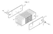
- Fig. 2 is a perspective view of an embodiment of a solid oxide fuel cell including the inventive device comprising the integral one-piece unit corresponding to the current collector and the manifold.
- Fig. 3 schematically shows the structure of a conventional flat tubular solid oxide fuel cell.
- FIG. 4 shows a stack of conventional flat tubular solid oxide fuel cells.
- first layer is referred to as being "on" a second layer or “on” a substrate, it not only refers to the case where the first layer is formed directly on the second layer or the substrate, but also the case where a third layer exists between the first layer and the second layer or the substrate.
- An aspect of the present invention provides a device for a solid oxide fuel cell or a solid oxide electrolysis cell, the device comprising an integral one-piece unit corresponding to a current collector and a manifold.
- current collector refers to a device that collects electricity generated in a cell stack.
- the term "manifold” means a component through which required gas (hydrogen, nitrogen, steam, oxygen, etc.) is supplied to, or discharged from a fuel cell or an electrolysis cell.
- integrated means that two components are formed integrally with each other without having to use a separate joining element.
- the solid oxide fuel cell comprises a stack of unit cells, each comprising an anode, an electrolyte, a cathode, and the like.
- the solid oxide electrolysis cell is very similar to the solid oxide fuel cell with respect to material and structure, but is a device that electrolyzes water (H 2 O) into hydrogen (H 2 ) and oxygen (O 2 ) by an electrochemical reverse reaction to that of the solid oxide fuel cell and has the same configuration as the solid oxide fuel cell.
- the current collector and the manifold are provided as separate components (see Fig. 3 ), and a brazing or thermal bonding process is carried out to connect the two components with each other.
- the device comprising an integral one-piece unit corresponding to a current collector and a manifold, the brazing or thermal bonding process which has been recognized as a necessary step in the conventional manufacture of tubular or flat tubular solid oxide fuel cells or solid oxide electrolysis cells is omitted. Accordingly, little or no stress occurs at the connection portion that connects the current collector to the manifold, and thus a breakdown of the junction between the current collector and the manifold or gas leakage through the junction can be prevented, and the inventive device can be used for a long period of time.
- the current collector and the manifold are jointed together mainly by a seal such as glass or metal.
- the solid oxide fuel cell has a coefficient of thermal expansion of about 11 x 10 -6
- the glass seal has a coefficient of thermal expansion of about 5-6 x 10 -11
- the metal cap has a coefficient of thermal expansion of about 12-13 x 10 -6 .
- the inventive device for a solid oxide fuel cell or a solid oxide electrolysis cell which comprises an integral one-piece construction of a current collector and a manifold, is free from tensile stress caused by the difference in the coefficients of thermal expansion.
- the three components can be provided as an integral component according to an embodiment of the present invention.
- components are easy to store and manage, and the volume of a tubular or flat tubular solid oxide fuel cell or solid oxide electrolysis cell can advantageously be reduced (see Example 4).
- the inventive device for a solid oxide fuel cell or a solid oxide electrolysis cell which comprises an integral one-piece construction of a current collector and a manifold, is preferably used in a tubular solid oxide fuel cell or solid oxide electrolysis fuel cell, but is not limited thereto.
- Such an inventive device comprising a current collector and a manifold is characterized in that the device is for a solid oxide fuel cell or a solid oxide electrolysis cell and the manifold is integrated into the current collector.
- the inventive device for a solid oxide fuel cell or a solid oxide electrolysis cell which comprises an integral one-piece construction of a current collector and a manifold, is disposed adjacent to the first and the last cells of a tubular solid cell stack consisting of a plurality of unit cells (see Fig. 2 ).
- the device includes a gas inlet or outlet port, which is connected horizontally to the connection hole of the flat tubular solid oxide cell stack consisting of the plurality of unit cells.
- the gas inlet or outlet port is preferably connected horizontally to the connection hole of the flat tubular solid oxide cell stack consisting of the plurality of unit cells.
- the device according to an aspect of the present invention is preferably configured such that the gas inlet or outlet port is connected with each of the connection holes exposed through the first and the last cells of the cell stack (see Fig. 2 ).
- An embodiment of the present invention also provides a solid oxide fuel cell or a solid oxide electrolysis cell, which comprises the above-described device comprising the integral one-piece construction of the current collector and the manifold.
- Fig. 1 is a perspective view of an inventive device for a solid oxide fuel cell or a solid oxide electrolysis cell according to an embodiment of the present invention, the device comprising an integral one-piece unit including a current collector and a manifold.
- a device 1 for a solid oxide fuel cell or a solid oxide electrolysis cell which comprises an integral one-piece construction of a current collector and a manifold, comprises a metal plate 4 serving as a current collector, and a tube 2 serving as a manifold, the metal plate 4 being integral with the tube 2.
- the tube 2 serving as a manifold includes a gas inlet or outlet port 3.
- the device 1 comprising the integral one-piece construction of the current collector and the manifold can be manufactured by injection, extrusion, or press molding, but is not limited thereto.
- Fig. 2 is a perspective view of a solid oxide fuel cell having attached thereto the inventive device according to an embodiment of the present invention, comprising the integral one-piece construction of the current collector and the manifold.
- the device 1 comprising the integral one-piece construction of the current collector and the manifold is collected to a stack 5 of unit cells.
- the tube 2 serving as a manifold has a gas inlet or outlet port 3 which is connected horizontally to an air inlet port 6 of the cell stack 5.
- the direction in which the gas inlet or outlet port 3 is connected to the air inlet port 6 is not limited to the horizontal direction.
- Fig. 3 shows a manifold in a general, conventional flat tubular solid oxide fuel cell.
- a metal mesh 7 for current collection is placed on the electrodes of the unit cell 5a, and then a wire 8 is wound around the unit cell 5a, and a metal cap 9 for connection with a manifold and a tube 2a are separately provided. This increases the manufacturing time and cost.
- Fig. 4 shows a stack of general, conventional flat tubular solid fuel cells.
- the general, conventional flat tubular solid oxide fuel cells are stacked on top of each other, there is a disadvantage in that the volume of the cell stack significantly increases.
- a large amount of a noble metal for example, Pt or Ag as the wire 8 on the unit cell
- the manufacturing cost is high.
- Example 1 Comparison of reproducibility between a solid oxide fuel cell, comprising an integral one-piece construction of a current collector and a manifold, and a solid oxide fuel cell comprising a current collector separate from a manifold
- Example 2 Comparison of manifold junction time and stack manufacture time after unit cell manufacturing between a solid oxide fuel cell comprising an integral one-piece unit including a current collector and a manifold, and a solid oxide fuel cell comprising a current collector separate from a manifold
- Example 3 Comparison of manufacturing cost between a solid oxide fuel cell comprising an integral one-piece construction of a current collector and a manifold, and a solid oxide fuel cell comprising a current collector separate from a manifold
- Example 4 Comparison of volume between a solid oxide fuel cell comprising an integral one-piece unit including a current collector and a manifold, and a solid oxide fuel cell comprising a current collector separate from a manifold
- the inventive device for solid oxide fuel cells or solid oxide electrolysis cells which comprises the current collector formed integrally with the manifold, according to embodiments of the present invention, eliminates the need for the brazing or thermal bonding process for joining the manifold with the current collector, and thus makes it possible to prevent breakdown of the junction or gas leakage through the junction, and can be used for a long period of time.
Landscapes
- Chemical & Material Sciences (AREA)
- Engineering & Computer Science (AREA)
- Electrochemistry (AREA)
- Chemical Kinetics & Catalysis (AREA)
- Sustainable Development (AREA)
- Sustainable Energy (AREA)
- Life Sciences & Earth Sciences (AREA)
- Manufacturing & Machinery (AREA)
- General Chemical & Material Sciences (AREA)
- Inorganic Chemistry (AREA)
- Materials Engineering (AREA)
- Metallurgy (AREA)
- Organic Chemistry (AREA)
- Fuel Cell (AREA)
- Electrolytic Production Of Non-Metals, Compounds, Apparatuses Therefor (AREA)
Description
- This application claims priority to Korean Patent Application No.
10-2011-0130677, filed on December 8, 2011 - Exemplary embodiments of the present invention relate to a device for a solid oxide fuel cell or a solid oxide electrolysis cell, the device comprising an integral one-piece construction including a current collector and a manifold.
- A solid oxide fuel cell is a system that generates electricity by the reaction of fuel (hydrocarbon or hydrogen) with oxygen in the air at a high temperature of 500 to 1,000 °C. Similarly, a solid oxide electrolysis cell is a system that electrolyzes steam into hydrogen and oxygen at a high temperature of 500 to 1,000 °C.
- Such solid-oxide fuel cells or solid oxide electrolysis cells are generally classified by shape into a planar type, a tubular type and a flat tubular type.
- The planar solid oxide fuel cell, or electrolysis cell, has the advantage of a high power density (output power). However, the planar solid oxide fuel cell or electrolysis cell has disadvantages in that the area containing the gas seal is relatively large, thermal shock (thermal stress) occurs due to the difference in the coefficient of thermal expansion between materials during stacking and it is difficult to achieve a large electrode area.
- The tubular fuel cell has advantages in that it has a relatively high thermal stress resistance and mechanical strength, can be manufactured by extrusion molding and makes it possible to achieve a large electrode area. However, the tubular fuel cell has the limitation of low power density.
- The flat tubular fuel cell combines the advantages of the planar and tubular fuel cells (electrolysis cells).
- The flat tubular fuel cell is advantageous over the tubular fuel cell in that it has a relatively high power density (output power), thermal stress resistance and mechanical strength.
- In spite of such advantages, the tubular solid oxide fuel cell and electrolysis cell has a disadvantage in that it requires an excessively large number of stack components, including a unit cell, a connection material, a current collector, a manifold, a housing, an insulation material and a sealing material.
- Particularly, the current collector serves to collect electricity generated in a stack of unit cells at high temperature or to supply the electricity, and the manifold is an important component through which gas is supplied to the fuel stack or discharged therefrom. The two components are generally connected with each other.
- In conventional tubular or flat tubular solid oxide fuel cells and electrolysis cells, a metallic current collector is generally used to collect electricity generated in the cell stack, and the manifold for supplying gas to the cell stack is provided as a component separate from the current collector.
- In this case, a brazing or thermal bonding process for joining the manifold with the current collector is carried out, thus increasing the process time and the manufacturing cost.
- In addition, in the case of conventional tubular or flat tubular solid oxide fuel cells and electrolysis cells, a cell stack provided with the current collector separately from the manifold should be manufactured, and thus the total volume of the cell is increased.
- Furthermore, in the case of conventional tubular or flat tubular solid oxide fuel cells and electrolysis cells, a brazing process or a bonding process of joining the current collector with the manifold is carried out. In this process, stress can occur in the cell due to the difference in the coefficient of thermal expansion between materials, and thus the cell can be damaged or gas can leak from the cell during operation.
- Specifically, in the case of most of tubular or flat tubular fuel cells, a process of sealing with glass ceramic or a brazing process employing a metal filler is carried out to join a metal cap with a ceramic tube in order to seal the gas.
- However, in case the cell is sealed with glass ceramic, there is a problem in that the cell or the glass seal is broken down due to the difference in the coefficient of thermal expansion therebetween.
- In addition, when the metal cap and the ceramic tube are brazed using the metal filler, the difference in the coefficient of thermal expansion can be minimized, but the filler metal can be corroded and reduced during the brazing process, thus causing a problem in terms of the long-term stability of the cell. In addition, the filler metal has a low melting point, the operation of the cell at high temperature (850 °C or higher) is limited. Moreover, because the reducibility of the brazing process is very low, the process has a very low yield and is very expensive.
- Accordingly, the present inventors have conducted studies to solve the above-described problems and, as a result, have developed a device for a solid oxide fuel cell or a solid oxide electrolysis cell, the device comprising an integral one-piece unit including a current collector and a manifold, which corresponds to an aspect of the present invention.
-
- Patent Document 1:
KR 10-2010-0039971 - Patent Document 2:
KR 10-2010-0013827 - An embodiment of the present invention is to solve the problems with conventional solid oxide fuel cells or solid oxide hydrolysis cells in which the current collector is separate from the manifold.
- Other objects and advantages of the present invention can be understood by the following description, and will become apparent with reference to the embodiments of the present invention. Also, it is obvious to those skilled in the art to which the present invention pertains that the objects and advantages of the present invention can be realized by the means as claimed and combinations thereof.
- In accordance with an embodiment of the present invention, a device for a solid oxide fuel cell or a solid oxide electrolysis cell includes an integral one-piece unit corresponding to a current collector and a manifold.
- In accordance with another embodiment of the present invention, a solid oxide fuel cell includes said device comprising the integral one-piece unit corresponding to the current collector and the manifold.
- In accordance with still another embodiment of the present invention, a solid oxide hydrolysis cell includes said device comprising the integral one-piece unit corresponding to the current collector and the manifold.
-
Fig. 1 is a perspective view of an embodiment of an inventive device for a solid oxide fuel cell or a solid oxide electrolysis cell, the device comprising an integral one-piece unit corresponding to a current collector and a manifold. -
Fig. 2 is a perspective view of an embodiment of a solid oxide fuel cell including the inventive device comprising the integral one-piece unit corresponding to the current collector and the manifold. -
Fig. 3 schematically shows the structure of a conventional flat tubular solid oxide fuel cell. -
FIG. 4 shows a stack of conventional flat tubular solid oxide fuel cells. - Exemplary embodiments of the present invention will be described below in greater detail with reference to the accompanying drawings. The present invention may, however, be embodied in different forms, and should not be construed as being limited to the embodiments set forth herein. Rather, these embodiments are provided so that this disclosure will be thorough and complete, and will fully convey the scope of the present invention to those skilled in the art. Throughout the disclosure, like reference numerals refer to like parts throughout the various figures and embodiments of the present invention.
- The drawings are not necessarily to scale and, in some instances, proportions may have been exaggerated in order to clearly illustrate features of the embodiments. When a first layer is referred to as being "on" a second layer or "on" a substrate, it not only refers to the case where the first layer is formed directly on the second layer or the substrate, but also the case where a third layer exists between the first layer and the second layer or the substrate.
- Hereinafter, embodiments of the present invention will be described in further detail.
- An aspect of the present invention provides a device for a solid oxide fuel cell or a solid oxide electrolysis cell, the device comprising an integral one-piece unit corresponding to a current collector and a manifold.
- As used herein, the term "current collector" refers to a device that collects electricity generated in a cell stack.
- As used herein, the term "manifold" means a component through which required gas (hydrogen, nitrogen, steam, oxygen, etc.) is supplied to, or discharged from a fuel cell or an electrolysis cell.
- As used herein, the term "integrated" means that two components are formed integrally with each other without having to use a separate joining element.
- The solid oxide fuel cell (SOFC), according to an aspect of the present invention, comprises a stack of unit cells, each comprising an anode, an electrolyte, a cathode, and the like.
- The solid oxide electrolysis cell, according to an aspect of the present invention, is very similar to the solid oxide fuel cell with respect to material and structure, but is a device that electrolyzes water (H2O) into hydrogen (H2) and oxygen (O2) by an electrochemical reverse reaction to that of the solid oxide fuel cell and has the same configuration as the solid oxide fuel cell.
- In the case of conventional tubular or flat tubular solid oxide fuel cells or solid oxide electrolysis cells, the current collector and the manifold are provided as separate components (see
Fig. 3 ), and a brazing or thermal bonding process is carried out to connect the two components with each other. - In contrast, in the case of the inventive device for solid oxide fuel cells or solid oxide electrolysis cells, according to an embodiment of the present invention, the device comprising an integral one-piece unit corresponding to a current collector and a manifold, the brazing or thermal bonding process which has been recognized as a necessary step in the conventional manufacture of tubular or flat tubular solid oxide fuel cells or solid oxide electrolysis cells is omitted. Accordingly, little or no stress occurs at the connection portion that connects the current collector to the manifold, and thus a breakdown of the junction between the current collector and the manifold or gas leakage through the junction can be prevented, and the inventive device can be used for a long period of time.
- In the case of conventional tubular or flat tubular solid oxide fuel cells or solid oxide electrolysis cells, the current collector and the manifold are jointed together mainly by a seal such as glass or metal. In this case, the solid oxide fuel cell has a coefficient of thermal expansion of about 11 x 10-6, whereas the glass seal has a coefficient of thermal expansion of about 5-6 x 10-11, and the metal cap has a coefficient of thermal expansion of about 12-13 x 10-6. For this reason, tensile stress can occur in the glass seal or the cell, which is then broken down.
- In contrast, the inventive device for a solid oxide fuel cell or a solid oxide electrolysis cell, according to an embodiment of the present invention, which comprises an integral one-piece construction of a current collector and a manifold, is free from tensile stress caused by the difference in the coefficients of thermal expansion.
- In addition, when the current collector and the manifold are integrally formed, the reproducibility of the manifold seal, which has been recognized as a problem in the conventional manufacture of tubular or flat tubular solid oxide fuel cells or solid oxide electrolysis cells, can be increased to a reliable level, and the process required to connect the current collector to the manifold is omitted, and thus much time and cost can be saved (see Examples 1 to 3).
- Furthermore, unlike conventional tubular or flat tubular solid oxide fuel cells or solid oxide electrolysis cells in which the current collector, the manifold and a component for connecting them should be provided as separate components, the three components can be provided as an integral component according to an embodiment of the present invention. Thus, according to embodiments of the present invention, components are easy to store and manage, and the volume of a tubular or flat tubular solid oxide fuel cell or solid oxide electrolysis cell can advantageously be reduced (see Example 4).
- The inventive device for a solid oxide fuel cell or a solid oxide electrolysis cell, according to an embodiment of the present invention, which comprises an integral one-piece construction of a current collector and a manifold, is preferably used in a tubular solid oxide fuel cell or solid oxide electrolysis fuel cell, but is not limited thereto.
- Such an inventive device comprising a current collector and a manifold is characterized in that the device is for a solid oxide fuel cell or a solid oxide electrolysis cell and the manifold is integrated into the current collector.
- In an embodiment, the inventive device for a solid oxide fuel cell or a solid oxide electrolysis cell, which comprises an integral one-piece construction of a current collector and a manifold, is disposed adjacent to the first and the last cells of a tubular solid cell stack consisting of a plurality of unit cells (see
Fig. 2 ). - In addition, the device according to an aspect of the present invention includes a gas inlet or outlet port, which is connected horizontally to the connection hole of the flat tubular solid oxide cell stack consisting of the plurality of unit cells.
- In addition, the gas inlet or outlet port is preferably connected horizontally to the connection hole of the flat tubular solid oxide cell stack consisting of the plurality of unit cells. Moreover, the device according to an aspect of the present invention is preferably configured such that the gas inlet or outlet port is connected with each of the connection holes exposed through the first and the last cells of the cell stack (see
Fig. 2 ). - An embodiment of the present invention also provides a solid oxide fuel cell or a solid oxide electrolysis cell, which comprises the above-described device comprising the integral one-piece construction of the current collector and the manifold.
- Hereinafter, aspects of the present invention will be described in detail with reference to the following embodiment and the accompanying drawings so that those skilled in the art can easily carry out the present invention. However, the following embodiment is provided to more specifically describe aspects of the present invention, and the scope of the present invention is not limited by the described aspects. In addition, those skilled in the art will appreciate that various modifications, additions and substitutions are possible, without departing from the scope and spirit of the invention.
-
Fig. 1 is a perspective view of an inventive device for a solid oxide fuel cell or a solid oxide electrolysis cell according to an embodiment of the present invention, the device comprising an integral one-piece unit including a current collector and a manifold. - As shown in
Fig. 1 , adevice 1 for a solid oxide fuel cell or a solid oxide electrolysis cell, which comprises an integral one-piece construction of a current collector and a manifold, comprises ametal plate 4 serving as a current collector, and atube 2 serving as a manifold, themetal plate 4 being integral with thetube 2. Thetube 2 serving as a manifold includes a gas inlet oroutlet port 3. - The
device 1 comprising the integral one-piece construction of the current collector and the manifold can be manufactured by injection, extrusion, or press molding, but is not limited thereto. -
Fig. 2 is a perspective view of a solid oxide fuel cell having attached thereto the inventive device according to an embodiment of the present invention, comprising the integral one-piece construction of the current collector and the manifold. As shown inFig. 2 , thedevice 1 comprising the integral one-piece construction of the current collector and the manifold is collected to a stack 5 of unit cells. In addition, thetube 2 serving as a manifold has a gas inlet oroutlet port 3 which is connected horizontally to anair inlet port 6 of the cell stack 5. However, the direction in which the gas inlet oroutlet port 3 is connected to theair inlet port 6 is not limited to the horizontal direction. -
Fig. 3 shows a manifold in a general, conventional flat tubular solid oxide fuel cell. As shown inFig. 3 , in order to manufacture the general solid oxide fuel cell, ametal mesh 7 for current collection is placed on the electrodes of theunit cell 5a, and then awire 8 is wound around theunit cell 5a, and ametal cap 9 for connection with a manifold and atube 2a are separately provided. This increases the manufacturing time and cost. - In addition, in the case of
Fig. 3 , a separate process for joining themetal cap 8 to theunit cell 5a should be carried out, and thus the reproducibility of the solid oxide fuel cell is significantly reduced. -
Fig. 4 shows a stack of general, conventional flat tubular solid fuel cells. As shown inFig. 4 , when the general, conventional flat tubular solid oxide fuel cells are stacked on top of each other, there is a disadvantage in that the volume of the cell stack significantly increases. In addition, a large amount of a noble metal (for example, Pt or Ag as thewire 8 on the unit cell) is required to manufacture the individual solid oxide fuel cell unit, and thus the manufacturing cost is high. - In order to confirm the significant effects of the inventive solid oxide fuel cell comprising the integral one-piece construction of the current collector and the manifold, according to an embodiment of the present invention, tests were carried out to compare an inventive fuel cell with a solid oxide fuel cell comprising a current collector separate from a manifold.
- Example 1: Comparison of reproducibility between a solid oxide fuel cell, comprising an integral one-piece construction of a current collector and a manifold, and a solid oxide fuel cell comprising a current collector separate from a manifold
- 100 flat tubular solid oxide fuel cells (1 kW stack), comprising an integral one-piece unit including a current collector and a manifold, and 100 solid oxide fuel cells (1 kW stack) comprising a current collector separate from a manifold is applied, were manufactured, and reproducibility was compared between the two types of fuel cells. The comparison of the reproducibility was performed by counting the number of fuel cells showing the same effect among the manufactured solid oxide fuel cells. The results of the comparison are shown in Table 1 below.
-
[Table 1] Reproducibility of solid oxide fuel cells comprising the integral one-piece construction of the current collector and the manifold Reproducibility of solid oxide fuel cells comprising current collector separate from the manifold 95% (95 of 100 manufactured cells showed significant results) 15% (15 of 100 manufactured cells showed significant results) - Example 2: Comparison of manifold junction time and stack manufacture time after unit cell manufacturing between a solid oxide fuel cell comprising an integral one-piece unit including a current collector and a manifold, and a solid oxide fuel cell comprising a current collector separate from a manifold
- After the manufacture of unit cells for each solid oxide fuel cell, comprising an integral one-piece construction of a current collector and a manifold, and a solid oxide fuel cell comprising a current collector separate from a manifold, the times required for both manifold junction and stack manufacturing were compared between the two types of fuel cells. The results of the comparison are shown in Table 2 below.
-
[Table 2] Manufacturing time of solid oxide fuel cell comprising the integral one-piece construction of the current collector and the manifold Solid oxide fuel cell comprising a current collector separate from the manifold Stack manufacturing and cable connection 1 hour Manifold junction 24 hours Placement of mesh for current collection and wire 6 hours Stack manufacturing and cable connection 3 hours - Example 3: Comparison of manufacturing cost between a solid oxide fuel cell comprising an integral one-piece construction of a current collector and a manifold, and a solid oxide fuel cell comprising a current collector separate from a manifold
- Manufacturing cost was compared between a solid oxide fuel cell, comprising an integral one-piece unit including a current collector and a manifold, and a solid oxide fuel cell comprising a current collector separate from a manifold. The results of the comparison are shown in Table 3 below.
- [Table 3]
Manufacturing cost of solid oxide fuel cell comprising the integral one-piece unit including the current collector and the manifold Manufacturing cost of solid oxide fuel cell comprising a current collector separate from manifold 3.4 million Won in Korean currency 8.5 million Won in Korean currency - Example 4: Comparison of volume between a solid oxide fuel cell comprising an integral one-piece unit including a current collector and a manifold, and a solid oxide fuel cell comprising a current collector separate from a manifold
- The volume of a solid oxide fuel cell comprising an integral one-piece unit including a current collector and a manifold was compared with that of a solid oxide fuel cell comprising a current collector separate from a manifold. The results of the comparison are shown in Table 4 below.
- [Table 4]
Volume of a solid oxide fuel cell comprising the integral one-piece unit including the current collector and the manifold Volume of a solid oxide fuel cell comprising a current collector separate from manifold 2,625 cm3 14,500 cm3 - As described above, the inventive device for solid oxide fuel cells or solid oxide electrolysis cells, which comprises the current collector formed integrally with the manifold, according to embodiments of the present invention, eliminates the need for the brazing or thermal bonding process for joining the manifold with the current collector, and thus makes it possible to prevent breakdown of the junction or gas leakage through the junction, and can be used for a long period of time.
- While the present invention has been described with respect to specific embodiments thereof, it will be apparent to those skilled in the art that various changes and modifications may be made without departing from the spirit and scope of the invention as defined in the following claims.
Claims (7)
- A device for a solid oxide fuel cell or a solid oxide electrolysis cell, the device comprising an integral one-piece unit that includes a current collector and a manifold.
- The device of claim 1, characterized in that the solid oxide fuel cell or the solid oxide electrolysis cell is of a flat tubular type.
- A solid oxide fuel cell comprising the device of claim 1.
- A solid oxide electrolysis cell comprising the device of claim 1.
- The solid oxide cell of claim 3 or claim 4, characterized in that the device is disposed adjacent to first and last cells of a flat tubular solid oxide cell stack that includes a plurality of unit cells.
- The solid oxide cell of claim 5, characterized in that the device includes a gas inlet or outlet port connected horizontally to a connection hole of the flat tubular solid oxide cell stack that includes the plurality of unit cells.
- The solid oxide cell of claim 6, characterized in that the gas inlet or outlet port of the device is connected to each of a plurality of connection holes exposed through the first and the last cells of the cell stack.
Applications Claiming Priority (1)
| Application Number | Priority Date | Filing Date | Title |
|---|---|---|---|
| KR1020110130677A KR101334930B1 (en) | 2011-12-08 | 2011-12-08 | An equipment for a solid oxide fuel cell or solid oxide electrolysis cell |
Publications (2)
| Publication Number | Publication Date |
|---|---|
| EP2602852A1 true EP2602852A1 (en) | 2013-06-12 |
| EP2602852B1 EP2602852B1 (en) | 2018-04-11 |
Family
ID=46650434
Family Applications (1)
| Application Number | Title | Priority Date | Filing Date |
|---|---|---|---|
| EP12180524.6A Active EP2602852B1 (en) | 2011-12-08 | 2012-08-15 | Device for solid oxide fuel cell or solid oxide electrolysis cell comprising integral one-piece current collector and manifold |
Country Status (3)
| Country | Link |
|---|---|
| US (1) | US8932779B2 (en) |
| EP (1) | EP2602852B1 (en) |
| KR (1) | KR101334930B1 (en) |
Families Citing this family (1)
| Publication number | Priority date | Publication date | Assignee | Title |
|---|---|---|---|---|
| DK3893300T3 (en) * | 2020-04-07 | 2023-11-06 | Korea Inst Energy Res | Flat Tubular Solid Oxide Fuel Cell or Water Electrolysis Cell with Integrated Current Collector and Manufacturing Method Therefor |
Citations (4)
| Publication number | Priority date | Publication date | Assignee | Title |
|---|---|---|---|---|
| US20010028973A1 (en) * | 2000-04-10 | 2001-10-11 | Honeywell International, Inc. | Stacking and manifolding of unitized solid oxide fuel cells |
| KR20100039971A (en) | 2008-10-09 | 2010-04-19 | 삼성네트웍스 주식회사 | System and method for managing location information |
| US20110065022A1 (en) * | 2009-09-14 | 2011-03-17 | Min Kyong Bok | Solid oxide fuel cell |
| US20120015275A1 (en) * | 2010-07-16 | 2012-01-19 | Samsung Sdi Co., Ltd. | Solid oxide fuel cell and fuel cell stack |
Family Cites Families (8)
| Publication number | Priority date | Publication date | Assignee | Title |
|---|---|---|---|---|
| US6423436B1 (en) * | 2000-03-30 | 2002-07-23 | The United States Of America As Represented By The United States Department Of Energy | Tubular electrochemical devices with lateral fuel aperatures for increasing active surface area |
| WO2004071150A2 (en) * | 2003-02-14 | 2004-08-26 | Global Thermoelectric Inc. | Sofc with floating current collectors |
| US7014934B2 (en) * | 2003-03-18 | 2006-03-21 | Ford Motor Company | Tubular flat plate fuel cells and method of making the same |
| US7629069B2 (en) | 2004-09-09 | 2009-12-08 | Nanodynamics Energy, Inc. | Solid oxide fuel cell system |
| KR100954432B1 (en) * | 2007-12-31 | 2010-04-27 | (주)퓨얼셀 파워 | Fuel cell stack with gasket integrated current collector |
| KR20110094448A (en) | 2010-02-16 | 2011-08-24 | 한국에너지기술연구원 | Bundle of individual cell-assembled solid oxide fuel cell and its manufacturing method |
| KR101146568B1 (en) * | 2010-04-07 | 2012-05-16 | 한국과학기술원 | Stack of solid oxide fuel cell |
| KR101142685B1 (en) | 2010-04-29 | 2012-07-11 | 삼성에스디아이 주식회사 | An Anode Supported Solid Oxide Fuel Cell |
-
2011
- 2011-12-08 KR KR1020110130677A patent/KR101334930B1/en not_active Expired - Fee Related
-
2012
- 2012-08-15 EP EP12180524.6A patent/EP2602852B1/en active Active
- 2012-08-15 US US13/585,958 patent/US8932779B2/en active Active
Patent Citations (4)
| Publication number | Priority date | Publication date | Assignee | Title |
|---|---|---|---|---|
| US20010028973A1 (en) * | 2000-04-10 | 2001-10-11 | Honeywell International, Inc. | Stacking and manifolding of unitized solid oxide fuel cells |
| KR20100039971A (en) | 2008-10-09 | 2010-04-19 | 삼성네트웍스 주식회사 | System and method for managing location information |
| US20110065022A1 (en) * | 2009-09-14 | 2011-03-17 | Min Kyong Bok | Solid oxide fuel cell |
| US20120015275A1 (en) * | 2010-07-16 | 2012-01-19 | Samsung Sdi Co., Ltd. | Solid oxide fuel cell and fuel cell stack |
Also Published As
| Publication number | Publication date |
|---|---|
| KR20130064191A (en) | 2013-06-18 |
| KR101334930B1 (en) | 2013-11-29 |
| EP2602852B1 (en) | 2018-04-11 |
| US20130149631A1 (en) | 2013-06-13 |
| US8932779B2 (en) | 2015-01-13 |
Similar Documents
| Publication | Publication Date | Title |
|---|---|---|
| JP4587659B2 (en) | Manufacturing method of fuel cell stack | |
| US10497949B2 (en) | Electro-chemical reaction unit and fuel cell stack | |
| US10665870B2 (en) | Electrochemical reaction unit and fuel cell stack | |
| US10361440B2 (en) | Electrochemical reaction unit having a single cell including a current collector having a protrusion coated with an electrically conductive coat in contact with a cathode via a bonding layer and fuel cell stack | |
| US9997797B2 (en) | Electrochemical reaction unit and fuel cell stack | |
| JP2021174593A (en) | Electrochemical reaction cell stack | |
| KR101130126B1 (en) | Electrical Collector for Solid Oxide Fuel Cell Using Segmented Flat Tube Structure | |
| US11394039B2 (en) | Electro-chemical reaction unit having glass seal member composed of vertically long crystal grains, and electro-chemical reaction cell stack, and electro-chemical reaction unit production method comprising same | |
| JP7071422B2 (en) | Electrochemical reaction cell stack | |
| JP2018018694A (en) | Electrochemical reaction unit and electrochemical reaction cell stack | |
| US20190288322A1 (en) | Electrochemical cell stack | |
| JP6873944B2 (en) | Electrochemical reaction cell stack | |
| KR101348967B1 (en) | Unit cell of flat-tubular solid oxide fuel cell or solid oxide electrolyzer cell and flat-tubular solid oxide fuel cell and flat-tubular solid oxide electrolyzer using the same | |
| US8932779B2 (en) | Device for solid oxide fuel cell or solid oxide electrolysis cell comprising integral one-piece current collector and manifold | |
| JP2023080459A (en) | Electrochemical reaction cell stack | |
| JP5448917B2 (en) | Cell stack device, fuel cell module and fuel cell device | |
| JP5806104B2 (en) | FUEL CELL STACK DEVICE, FUEL CELL STACK CONNECTION DEVICE, AND FUEL CELL DEVICE | |
| US8968959B2 (en) | Method for fabrication of electrochemical energy converter and the electrochemical energy converter | |
| US11158878B2 (en) | Electrochemical reaction cell stack | |
| JP7042783B2 (en) | Electrochemical reaction cell stack | |
| JP6902511B2 (en) | Electrochemical reaction cell stack | |
| JP2012014864A (en) | Cell stack device, fuel battery module and fuel battery device | |
| JP2018014246A (en) | Electrochemical reaction unit and electrochemical reaction cell stack | |
| JP5300619B2 (en) | Fuel cell stack device, fuel cell module and fuel cell device | |
| JPH056774A (en) | Solid electrolyte type fuel cell |
Legal Events
| Date | Code | Title | Description |
|---|---|---|---|
| PUAI | Public reference made under article 153(3) epc to a published international application that has entered the european phase |
Free format text: ORIGINAL CODE: 0009012 |
|
| 17P | Request for examination filed |
Effective date: 20120815 |
|
| AK | Designated contracting states |
Kind code of ref document: A1 Designated state(s): AL AT BE BG CH CY CZ DE DK EE ES FI FR GB GR HR HU IE IS IT LI LT LU LV MC MK MT NL NO PL PT RO RS SE SI SK SM TR |
|
| AX | Request for extension of the european patent |
Extension state: BA ME |
|
| RBV | Designated contracting states (corrected) |
Designated state(s): AL AT BE BG CH CY CZ DE DK EE ES FI FR GB GR HR HU IE IS IT LI LT LU LV MC MK MT NL NO PL PT RO RS SE SI SK SM TR |
|
| 17Q | First examination report despatched |
Effective date: 20151012 |
|
| GRAP | Despatch of communication of intention to grant a patent |
Free format text: ORIGINAL CODE: EPIDOSNIGR1 |
|
| RIC1 | Information provided on ipc code assigned before grant |
Ipc: H01M 8/02 20160101AFI20170531BHEP Ipc: H01M 8/124 20160101ALN20170531BHEP Ipc: H01M 8/243 20160101ALN20170531BHEP Ipc: H01M 8/0247 20160101ALI20170531BHEP |
|
| INTG | Intention to grant announced |
Effective date: 20170622 |
|
| GRAJ | Information related to disapproval of communication of intention to grant by the applicant or resumption of examination proceedings by the epo deleted |
Free format text: ORIGINAL CODE: EPIDOSDIGR1 |
|
| GRAP | Despatch of communication of intention to grant a patent |
Free format text: ORIGINAL CODE: EPIDOSNIGR1 |
|
| INTC | Intention to grant announced (deleted) | ||
| RIC1 | Information provided on ipc code assigned before grant |
Ipc: H01M 8/0247 20160101ALI20171107BHEP Ipc: H01M 8/243 20160101ALN20171107BHEP Ipc: H01M 8/124 20160101ALN20171107BHEP Ipc: H01M 8/02 20160101AFI20171107BHEP |
|
| INTG | Intention to grant announced |
Effective date: 20171124 |
|
| GRAS | Grant fee paid |
Free format text: ORIGINAL CODE: EPIDOSNIGR3 |
|
| GRAA | (expected) grant |
Free format text: ORIGINAL CODE: 0009210 |
|
| AK | Designated contracting states |
Kind code of ref document: B1 Designated state(s): AL AT BE BG CH CY CZ DE DK EE ES FI FR GB GR HR HU IE IS IT LI LT LU LV MC MK MT NL NO PL PT RO RS SE SI SK SM TR |
|
| REG | Reference to a national code |
Ref country code: GB Ref legal event code: FG4D |
|
| REG | Reference to a national code |
Ref country code: CH Ref legal event code: EP |
|
| REG | Reference to a national code |
Ref country code: AT Ref legal event code: REF Ref document number: 988934 Country of ref document: AT Kind code of ref document: T Effective date: 20180415 |
|
| REG | Reference to a national code |
Ref country code: IE Ref legal event code: FG4D |
|
| REG | Reference to a national code |
Ref country code: DE Ref legal event code: R096 Ref document number: 602012044981 Country of ref document: DE |
|
| REG | Reference to a national code |
Ref country code: NL Ref legal event code: MP Effective date: 20180411 |
|
| REG | Reference to a national code |
Ref country code: LT Ref legal event code: MG4D |
|
| PG25 | Lapsed in a contracting state [announced via postgrant information from national office to epo] |
Ref country code: NL Free format text: LAPSE BECAUSE OF FAILURE TO SUBMIT A TRANSLATION OF THE DESCRIPTION OR TO PAY THE FEE WITHIN THE PRESCRIBED TIME-LIMIT Effective date: 20180411 |
|
| PG25 | Lapsed in a contracting state [announced via postgrant information from national office to epo] |
Ref country code: PL Free format text: LAPSE BECAUSE OF FAILURE TO SUBMIT A TRANSLATION OF THE DESCRIPTION OR TO PAY THE FEE WITHIN THE PRESCRIBED TIME-LIMIT Effective date: 20180411 Ref country code: FI Free format text: LAPSE BECAUSE OF FAILURE TO SUBMIT A TRANSLATION OF THE DESCRIPTION OR TO PAY THE FEE WITHIN THE PRESCRIBED TIME-LIMIT Effective date: 20180411 Ref country code: BG Free format text: LAPSE BECAUSE OF FAILURE TO SUBMIT A TRANSLATION OF THE DESCRIPTION OR TO PAY THE FEE WITHIN THE PRESCRIBED TIME-LIMIT Effective date: 20180711 Ref country code: LT Free format text: LAPSE BECAUSE OF FAILURE TO SUBMIT A TRANSLATION OF THE DESCRIPTION OR TO PAY THE FEE WITHIN THE PRESCRIBED TIME-LIMIT Effective date: 20180411 Ref country code: SE Free format text: LAPSE BECAUSE OF FAILURE TO SUBMIT A TRANSLATION OF THE DESCRIPTION OR TO PAY THE FEE WITHIN THE PRESCRIBED TIME-LIMIT Effective date: 20180411 Ref country code: NO Free format text: LAPSE BECAUSE OF FAILURE TO SUBMIT A TRANSLATION OF THE DESCRIPTION OR TO PAY THE FEE WITHIN THE PRESCRIBED TIME-LIMIT Effective date: 20180711 Ref country code: AL Free format text: LAPSE BECAUSE OF FAILURE TO SUBMIT A TRANSLATION OF THE DESCRIPTION OR TO PAY THE FEE WITHIN THE PRESCRIBED TIME-LIMIT Effective date: 20180411 Ref country code: ES Free format text: LAPSE BECAUSE OF FAILURE TO SUBMIT A TRANSLATION OF THE DESCRIPTION OR TO PAY THE FEE WITHIN THE PRESCRIBED TIME-LIMIT Effective date: 20180411 |
|
| PG25 | Lapsed in a contracting state [announced via postgrant information from national office to epo] |
Ref country code: GR Free format text: LAPSE BECAUSE OF FAILURE TO SUBMIT A TRANSLATION OF THE DESCRIPTION OR TO PAY THE FEE WITHIN THE PRESCRIBED TIME-LIMIT Effective date: 20180712 Ref country code: RS Free format text: LAPSE BECAUSE OF FAILURE TO SUBMIT A TRANSLATION OF THE DESCRIPTION OR TO PAY THE FEE WITHIN THE PRESCRIBED TIME-LIMIT Effective date: 20180411 Ref country code: HR Free format text: LAPSE BECAUSE OF FAILURE TO SUBMIT A TRANSLATION OF THE DESCRIPTION OR TO PAY THE FEE WITHIN THE PRESCRIBED TIME-LIMIT Effective date: 20180411 Ref country code: LV Free format text: LAPSE BECAUSE OF FAILURE TO SUBMIT A TRANSLATION OF THE DESCRIPTION OR TO PAY THE FEE WITHIN THE PRESCRIBED TIME-LIMIT Effective date: 20180411 |
|
| REG | Reference to a national code |
Ref country code: AT Ref legal event code: MK05 Ref document number: 988934 Country of ref document: AT Kind code of ref document: T Effective date: 20180411 |
|
| PG25 | Lapsed in a contracting state [announced via postgrant information from national office to epo] |
Ref country code: PT Free format text: LAPSE BECAUSE OF FAILURE TO SUBMIT A TRANSLATION OF THE DESCRIPTION OR TO PAY THE FEE WITHIN THE PRESCRIBED TIME-LIMIT Effective date: 20180813 |
|
| REG | Reference to a national code |
Ref country code: DE Ref legal event code: R097 Ref document number: 602012044981 Country of ref document: DE |
|
| PG25 | Lapsed in a contracting state [announced via postgrant information from national office to epo] |
Ref country code: AT Free format text: LAPSE BECAUSE OF FAILURE TO SUBMIT A TRANSLATION OF THE DESCRIPTION OR TO PAY THE FEE WITHIN THE PRESCRIBED TIME-LIMIT Effective date: 20180411 Ref country code: EE Free format text: LAPSE BECAUSE OF FAILURE TO SUBMIT A TRANSLATION OF THE DESCRIPTION OR TO PAY THE FEE WITHIN THE PRESCRIBED TIME-LIMIT Effective date: 20180411 Ref country code: DK Free format text: LAPSE BECAUSE OF FAILURE TO SUBMIT A TRANSLATION OF THE DESCRIPTION OR TO PAY THE FEE WITHIN THE PRESCRIBED TIME-LIMIT Effective date: 20180411 Ref country code: RO Free format text: LAPSE BECAUSE OF FAILURE TO SUBMIT A TRANSLATION OF THE DESCRIPTION OR TO PAY THE FEE WITHIN THE PRESCRIBED TIME-LIMIT Effective date: 20180411 Ref country code: CZ Free format text: LAPSE BECAUSE OF FAILURE TO SUBMIT A TRANSLATION OF THE DESCRIPTION OR TO PAY THE FEE WITHIN THE PRESCRIBED TIME-LIMIT Effective date: 20180411 Ref country code: SK Free format text: LAPSE BECAUSE OF FAILURE TO SUBMIT A TRANSLATION OF THE DESCRIPTION OR TO PAY THE FEE WITHIN THE PRESCRIBED TIME-LIMIT Effective date: 20180411 |
|
| PLBE | No opposition filed within time limit |
Free format text: ORIGINAL CODE: 0009261 |
|
| STAA | Information on the status of an ep patent application or granted ep patent |
Free format text: STATUS: NO OPPOSITION FILED WITHIN TIME LIMIT |
|
| PG25 | Lapsed in a contracting state [announced via postgrant information from national office to epo] |
Ref country code: IT Free format text: LAPSE BECAUSE OF FAILURE TO SUBMIT A TRANSLATION OF THE DESCRIPTION OR TO PAY THE FEE WITHIN THE PRESCRIBED TIME-LIMIT Effective date: 20180411 Ref country code: SM Free format text: LAPSE BECAUSE OF FAILURE TO SUBMIT A TRANSLATION OF THE DESCRIPTION OR TO PAY THE FEE WITHIN THE PRESCRIBED TIME-LIMIT Effective date: 20180411 |
|
| 26N | No opposition filed |
Effective date: 20190114 |
|
| PG25 | Lapsed in a contracting state [announced via postgrant information from national office to epo] |
Ref country code: MC Free format text: LAPSE BECAUSE OF FAILURE TO SUBMIT A TRANSLATION OF THE DESCRIPTION OR TO PAY THE FEE WITHIN THE PRESCRIBED TIME-LIMIT Effective date: 20180411 |
|
| REG | Reference to a national code |
Ref country code: CH Ref legal event code: PL |
|
| GBPC | Gb: european patent ceased through non-payment of renewal fee |
Effective date: 20180815 |
|
| PG25 | Lapsed in a contracting state [announced via postgrant information from national office to epo] |
Ref country code: LI Free format text: LAPSE BECAUSE OF NON-PAYMENT OF DUE FEES Effective date: 20180831 Ref country code: LU Free format text: LAPSE BECAUSE OF NON-PAYMENT OF DUE FEES Effective date: 20180815 Ref country code: CH Free format text: LAPSE BECAUSE OF NON-PAYMENT OF DUE FEES Effective date: 20180831 |
|
| REG | Reference to a national code |
Ref country code: BE Ref legal event code: MM Effective date: 20180831 |
|
| REG | Reference to a national code |
Ref country code: IE Ref legal event code: MM4A |
|
| PG25 | Lapsed in a contracting state [announced via postgrant information from national office to epo] |
Ref country code: SI Free format text: LAPSE BECAUSE OF FAILURE TO SUBMIT A TRANSLATION OF THE DESCRIPTION OR TO PAY THE FEE WITHIN THE PRESCRIBED TIME-LIMIT Effective date: 20180411 |
|
| PG25 | Lapsed in a contracting state [announced via postgrant information from national office to epo] |
Ref country code: IE Free format text: LAPSE BECAUSE OF NON-PAYMENT OF DUE FEES Effective date: 20180815 |
|
| PG25 | Lapsed in a contracting state [announced via postgrant information from national office to epo] |
Ref country code: BE Free format text: LAPSE BECAUSE OF NON-PAYMENT OF DUE FEES Effective date: 20180831 Ref country code: FR Free format text: LAPSE BECAUSE OF NON-PAYMENT OF DUE FEES Effective date: 20180831 |
|
| PG25 | Lapsed in a contracting state [announced via postgrant information from national office to epo] |
Ref country code: GB Free format text: LAPSE BECAUSE OF NON-PAYMENT OF DUE FEES Effective date: 20180815 |
|
| PG25 | Lapsed in a contracting state [announced via postgrant information from national office to epo] |
Ref country code: MT Free format text: LAPSE BECAUSE OF NON-PAYMENT OF DUE FEES Effective date: 20180815 |
|
| PG25 | Lapsed in a contracting state [announced via postgrant information from national office to epo] |
Ref country code: TR Free format text: LAPSE BECAUSE OF FAILURE TO SUBMIT A TRANSLATION OF THE DESCRIPTION OR TO PAY THE FEE WITHIN THE PRESCRIBED TIME-LIMIT Effective date: 20180411 |
|
| PG25 | Lapsed in a contracting state [announced via postgrant information from national office to epo] |
Ref country code: HU Free format text: LAPSE BECAUSE OF FAILURE TO SUBMIT A TRANSLATION OF THE DESCRIPTION OR TO PAY THE FEE WITHIN THE PRESCRIBED TIME-LIMIT; INVALID AB INITIO Effective date: 20120815 |
|
| PG25 | Lapsed in a contracting state [announced via postgrant information from national office to epo] |
Ref country code: CY Free format text: LAPSE BECAUSE OF FAILURE TO SUBMIT A TRANSLATION OF THE DESCRIPTION OR TO PAY THE FEE WITHIN THE PRESCRIBED TIME-LIMIT Effective date: 20180411 Ref country code: MK Free format text: LAPSE BECAUSE OF NON-PAYMENT OF DUE FEES Effective date: 20180411 |
|
| PG25 | Lapsed in a contracting state [announced via postgrant information from national office to epo] |
Ref country code: IS Free format text: LAPSE BECAUSE OF FAILURE TO SUBMIT A TRANSLATION OF THE DESCRIPTION OR TO PAY THE FEE WITHIN THE PRESCRIBED TIME-LIMIT Effective date: 20180811 |
|
| PGFP | Annual fee paid to national office [announced via postgrant information from national office to epo] |
Ref country code: DE Payment date: 20250618 Year of fee payment: 14 |