EP2602695A1 - Dispositif d'entrée de données à potentiomètre et manche destiné au pilotage d'un aéronef, le manche comprenant le dispositif d'entrée de données - Google Patents
Dispositif d'entrée de données à potentiomètre et manche destiné au pilotage d'un aéronef, le manche comprenant le dispositif d'entrée de données Download PDFInfo
- Publication number
- EP2602695A1 EP2602695A1 EP12196012.4A EP12196012A EP2602695A1 EP 2602695 A1 EP2602695 A1 EP 2602695A1 EP 12196012 A EP12196012 A EP 12196012A EP 2602695 A1 EP2602695 A1 EP 2602695A1
- Authority
- EP
- European Patent Office
- Prior art keywords
- voltage
- potentiometer
- connection point
- slider
- fixed
- Prior art date
- Legal status (The legal status is an assumption and is not a legal conclusion. Google has not performed a legal analysis and makes no representation as to the accuracy of the status listed.)
- Granted
Links
Images
Classifications
-
- G—PHYSICS
- G01—MEASURING; TESTING
- G01R—MEASURING ELECTRIC VARIABLES; MEASURING MAGNETIC VARIABLES
- G01R27/00—Arrangements for measuring resistance, reactance, impedance, or electric characteristics derived therefrom
- G01R27/02—Measuring real or complex resistance, reactance, impedance, or other two-pole characteristics derived therefrom, e.g. time constant
-
- G—PHYSICS
- G06—COMPUTING OR CALCULATING; COUNTING
- G06F—ELECTRIC DIGITAL DATA PROCESSING
- G06F3/00—Input arrangements for transferring data to be processed into a form capable of being handled by the computer; Output arrangements for transferring data from processing unit to output unit, e.g. interface arrangements
- G06F3/01—Input arrangements or combined input and output arrangements for interaction between user and computer
- G06F3/03—Arrangements for converting the position or the displacement of a member into a coded form
- G06F3/033—Pointing devices displaced or positioned by the user, e.g. mice, trackballs, pens or joysticks; Accessories therefor
- G06F3/038—Control and interface arrangements therefor, e.g. drivers or device-embedded control circuitry
- G06F3/0383—Signal control means within the pointing device
-
- G—PHYSICS
- G06—COMPUTING OR CALCULATING; COUNTING
- G06F—ELECTRIC DIGITAL DATA PROCESSING
- G06F3/00—Input arrangements for transferring data to be processed into a form capable of being handled by the computer; Output arrangements for transferring data from processing unit to output unit, e.g. interface arrangements
- G06F3/01—Input arrangements or combined input and output arrangements for interaction between user and computer
- G06F3/03—Arrangements for converting the position or the displacement of a member into a coded form
- G06F3/033—Pointing devices displaced or positioned by the user, e.g. mice, trackballs, pens or joysticks; Accessories therefor
- G06F3/0354—Pointing devices displaced or positioned by the user, e.g. mice, trackballs, pens or joysticks; Accessories therefor with detection of two-dimensional [2D] relative movements between the device, or an operating part thereof, and a plane or surface, e.g. 2D mice, trackballs, pens or pucks
- G06F3/03548—Sliders, in which the moving part moves in a plane
-
- G—PHYSICS
- G06—COMPUTING OR CALCULATING; COUNTING
- G06F—ELECTRIC DIGITAL DATA PROCESSING
- G06F3/00—Input arrangements for transferring data to be processed into a form capable of being handled by the computer; Output arrangements for transferring data from processing unit to output unit, e.g. interface arrangements
- G06F3/01—Input arrangements or combined input and output arrangements for interaction between user and computer
- G06F3/03—Arrangements for converting the position or the displacement of a member into a coded form
- G06F3/033—Pointing devices displaced or positioned by the user, e.g. mice, trackballs, pens or joysticks; Accessories therefor
- G06F3/0362—Pointing devices displaced or positioned by the user, e.g. mice, trackballs, pens or joysticks; Accessories therefor with detection of one-dimensional [1D] translations or rotations of an operating part of the device, e.g. scroll wheels, sliders, knobs, rollers or belts
-
- H—ELECTRICITY
- H01—ELECTRIC ELEMENTS
- H01C—RESISTORS
- H01C10/00—Adjustable resistors
- H01C10/30—Adjustable resistors the contact sliding along resistive element
Definitions
- the invention relates to a data input device implementing a potentiometer. This type of device is used to know the value of a parameter that can evolve continuously, such as a displacement.
- This type of device is for example found in the aeronautical field and more specifically in a handle used for piloting aircraft, aircraft or helicopters.
- the pilot maneuvers this handle to change the attitude of his aircraft. It is important to know precisely the position of the handle to pass on the orders of the pilot.
- the handle is commonly disposed between the legs of the pilot and has several degrees of freedom thus allowing the pilot to control several types of moving parts of his aircraft such as for example the fins and the elevator.
- the handle can for example be mobile following two rotations or a rotation and a translation.
- mini sleeves well known in the Anglo-Saxon literature under the name of "joystick” still allowing the pilot to control his aircraft.
- the invention is concerned with the conversion into electrical information of the movements of the handle. More specifically, the handle has for each degree of freedom, at least one potentiometer for converting the position of the handle into electrical information in the form of a DC voltage.
- the potentiometer may be rotatable to convert a rotation of the handle or linear to convert a translation of a handle or a mini-stick.
- the invention is not limited to a handle for controlling an aircraft.
- the invention can be implemented for any use of a potentiometer.
- fault detection can be difficult to implement. A lack of continuity may only become apparent when moving the cursor, which may be critical to the mission of an aircraft. The pilot would then notice a defect in his grip only when he wants to maneuver his aircraft.
- the invention makes it possible to guarantee a minimum current in the potentiometer while maintaining the linearity of the measurement.
- the invention also relates to a handle for controlling an aircraft, the handle comprising a data input device according to the invention.
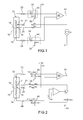
- the figure 1 represents a data input device comprising a potentiometer 10 of which a slider 11 can be moved.
- the potentiometer 10 comprises a resistor 12 extending between two ends 13 and 14.
- the slider 11 can move along the resistor 12 to ensure electrical contact with a current point of the resistor 12 located between the two ends 13 and 14 .
- the resistor 12 is fixed relative to the cockpit and the slider 11 is secured to a movable portion of the handle, a movable portion intended to be operated by a pilot of the aircraft.
- the resistor 12 can be mobile and the slider 11 fixed.
- the main function of the data input device is to convert the position of the slider 11 into electrical information which is for example used to control an actuator.
- Potentiometer 10 has a midpoint 15. More precisely, it is possible to establish a fixed electrical contact with the resistor in the middle of the latter. In other words, for a total value R of the resistor 12, there is an R / 2 value between each of the ends 13 and 14 and the midpoint 15.
- the invention can be implemented with a fixed connection point which can be located at another position of the resistor than in the middle of it. This connection point is simply located at an intermediate position between the two ends 13 and 14. It is sufficient that this intermediate point is separate from the two ends 13 and 14.
- the device may comprise a connector comprising four connection terminals 21, 23, 24 and 25 each making it possible to connect one of the points of the potentiometer 10, respectively 11, 13, 14 and 15, to other components of the device. It is also possible to do without a connector and ensure an irremovable connection for example by welding.
- the device comprises means for supplying the potentiometer 10 via its midpoint 15 by means of a first fixed voltage.
- a voltage source V + is connected to the connection terminal 25, and therefore to the midpoint 15, via a resistor R1.
- the device comprises means for supplying the potentiometer 10 by the slider 11 by means of a current source.
- a constant current generator Ic is connected to the connection terminal 21, and therefore to the slider 11, via a resistor R2.
- the current generator Ic uses a fixed voltage V- of negative value relative to that of the ground 35 in order to establish the current leaving the potentiometer 10 by the slider 11.
- the device comprises means for measuring a voltage difference between the ends 13 and 14. This voltage difference forms the electrical voltage representative of the position of the slider 11 between the ends 13 and 14 along the resistor 12 of the potentiometer 10.
- the device comprises two voltage dividers 33 and 34. These dividers make it possible to guarantee the circulation of a minimum current in the ends 13 and 14 of the potentiometer 10.
- the first divider 33 is connected between the terminal 23 and a fixed voltage formed for example by an electric ground 35 of the device.
- the second divider 34 is connected between the terminal 24 and a fixed voltage also formed for example by the mass 35 of the device.
- the divider 33 is for example formed of two resistors R11 and R21 connected in series between the terminal 23 and the ground 35. The common point of the two resistors R11 and R21 forms an intermediate point 43 of the divider 33.
- the divider 34 is for example formed of two resistors R12 and R22 connected in series between the terminal 14 and the ground 35. The common point of the two resistors R12 and R22 forms an intermediate point 44 of the divider 34.
- the two voltage dividers 33 and 34 are advantageously identical. More precisely, on the one hand, the resistors R11 and R12 have the same value and, on the other hand, the resistors R21 and R22 have the same value.
- the difference in voltage is measured between the two intermediate points 43 and 44, for example by means of a voltmeter 50 whose output 51 delivers a voltage representative of the position of the slider 11 along the resistor 12.
- V + forms a positive voltage source and an opposite voltage source V- is used to establish the constant current Ic leaving the potentiometer 10 by the slider 11.
- the two voltages have opposite values V + and V- with respect to the mass 35.
- the figure 2 represents an embodiment of the device of the figure 1 wherein the resistor R1 is selected at 1k ⁇ , the resistor R2 at 5k ⁇ and the resistors R11, R21, R12 and R22 at 2.5k ⁇ .
- the current generator Ic is formed by a transistor T connected between the resistor R2 and the voltage source V- via a resistor R4 whose value is chosen at 2.5k ⁇ .
- the transistor T is controlled so as to maintain a constant voltage, here 5V across the resistor R4 and a constant current flowing in the resistor R4.
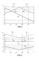
- the Figures 3 and 4 represent the evolution of voltages and currents in the device of the figure 2 according to the position of the cursor 11. More precisely, in these two figures, the horizontal axis represents the position of the cursor 11 which conventionally evolves between two values 0 and 1, "0" representing the cursor 11 at point 14 and " 1 "representing cursor 11 at point 13.
- the vertical axis represents the voltage at certain characteristic points of the device.
- a mixed line curve represents the evolution of the voltage V 43 at point 43
- a dashed line curve represents the evolution of the voltage V 44 at point 44
- a continuous line curve represents the evolution of the voltage V 51 at point 51.
- the voltage V 51 is equal to the difference between the voltages V 43 and V 44 . It can be seen that the evolution of the voltage V 51 is linear over the entire movement of the slider 11, which is sought to ensure the determination of the position of the slider 11.
- the vertical axis represents the intensity of the current flowing at certain characteristic points of the device.
- the current generator Ic delivers a constant current I 21 of -2A.
- a dashed line curve represents the evolution of the current I 23 in the connection terminal 23
- a dashed line curve represents the variation of the current I 24 in the connection terminal 24
- a dash line represents the evolution of the current I 25 in the connection terminal 25. It is found that regardless of the position of the slider 11, there is always a non-zero current flowing in each of the connection terminals 21, 23, 24 and 25.
- the values of the resistors are only given by way of example and can be modified as a function of the values of the desired voltage amplitude at the input and at the output of the voltmeter 50 and as a function of the intensities of the currents that the it is desired to circulate in the device.
- the device comprises means for measuring the voltage present at at least one of the connection terminals and means for comparing the value of the measured voltage with a reference value.
- Such monitoring makes it easy to diagnose device failure even when it is at rest especially in case of degradation and possibly loss of contact at one of the connection terminals 21, 23, 24 or 25. Indeed, any increase in resistance seen from the source current will result in a voltage variation on the monitored connection terminal, such as an increase in the voltage on the connection 21. A monitoring of this voltage will therefore diagnose faults even without moving the slider 11 of the potentiometer 10 .
- connection terminals 23 or 24 results in an increase of the voltage present at the connection terminal 21. This parameter is less sensitive. A variation of 10k ⁇ will result in an increase of 470mV. However, the value read will evolve, which can be detected by redundant monitoring.
Landscapes
- Engineering & Computer Science (AREA)
- General Engineering & Computer Science (AREA)
- Theoretical Computer Science (AREA)
- Physics & Mathematics (AREA)
- General Physics & Mathematics (AREA)
- Human Computer Interaction (AREA)
- Microelectronics & Electronic Packaging (AREA)
- Transmission And Conversion Of Sensor Element Output (AREA)
- Adjustable Resistors (AREA)
- Braking Arrangements (AREA)
- Measurement Of Length, Angles, Or The Like Using Electric Or Magnetic Means (AREA)
Abstract
Description
- L'invention concerne un dispositif d'entrée de données mettant en oeuvre un potentiomètre. Ce type de dispositif est utilisé pour connaître la valeur d'un paramètre susceptible d'évoluer de façon continue, comme par exemple un déplacement.
- On trouve par exemple ce type de dispositif dans le domaine aéronautique et plus précisément dans un manche utilisé pour le pilotage des aéronefs, avions ou hélicoptères. Le pilote manoeuvre ce manche pour modifier l'assiette de son appareil. Il est capital de connaitre avec précision la position du manche pour répercuter les ordres du pilote. Le manche est communément disposé entre les jambes du pilote et possède plusieurs degrés de libertés permettant ainsi au pilote de commander plusieurs types d'organes mobiles de son aéronef tels que par exemple les ailerons et la gouverne de profondeur. Le manche peut par exemple être mobile suivant deux rotations ou une rotation et une translation. Récemment sont apparus des manches de taille réduite appelés mini manches, bien connus dans la littérature anglo-saxonne sous le nom de « joystick » permettant toujours au pilote de commander son aéronef.
- L'invention s'intéresse à la conversion en information électrique des déplacements du manche. Plus précisément, le manche possède pour chaque degré de liberté, au moins un potentiomètre permettant de convertir la position du manche en information électrique sous forme d'une tension continue. Le potentiomètre peut être rotatif pour convertir une rotation du manche ou linéaire pour convertir une translation d'un manche ou d'un mini manche.
- L'invention n'est pas limitée à un manche permettant le pilotage d'un aéronef. L'invention peut être mise en oeuvre pour toute utilisation d'un potentiomètre.
- Il est connu d'appliquer une tension continue entre les deux extrémités du potentiomètre et de lire la tension présente sur le curseur du potentiomètre pour obtenir l'information recherchée. Cette lecture se fait à haute impédance pour éviter les pertes de linéarité entre la position du curseur et la tension lue. Cette haute impédance entraine un courant très faible qui ne permet pas de garantir une bonne continuité des contacts. Des défauts peuvent intervenir au niveau du contact du curseur dans le potentiomètre lui-même ou au niveau de contacts extérieurs au potentiomètre par exemple dans un connecteur le reliant à son environnement. L'utilisation de contacts dorés permet d'améliorer la qualité de la connectique mais n'apporte pas de solution parfaite aux problèmes dans la continuité des contacts.
- De plus, une détection de panne peut être difficile à mettre en oeuvre. Un défaut de continuité peut ne devenir apparent que lors d'un déplacement du curseur, ce qui peut être critique pour la mission d'un aéronef. Le pilote ne s'apercevrait alors d'un défaut de son manche que lorsqu'il souhaite manoeuvrer son aéronef.
- L'invention permet de garantir un courant minimal dans le potentiomètre tout en conservant la linéarité de la mesure.
- A cet effet, l'invention a pour objet un dispositif d'entrée de données comprenant un curseur et des moyens convertissant une position du curseur en une tension électrique, caractérisé en ce qu'il comprend en outre :
- un potentiomètre s'étendant entre deux extrémités, le potentiomètre possédant un premier et un deuxième points de connexion fixes situés respectivement à chacune des extrémités du potentiomètre, un troisième point de connexion fixe situé à une position intermédiaire du potentiomètre entre les deux extrémités et un quatrième point de connexion mobile formant le curseur et pouvant se déplacer entre les deux extrémités,
- des moyens pour alimenter le potentiomètre par le troisième point de connexion au moyen d'une première tension fixe,
- des moyens pour alimenter le potentiomètre par le curseur au moyen d'une source de courant,
- des moyens pour mesurer une différence de tension entre le premier et deuxième point de connexion, la différence de tension formant la tension électrique représentative de la position du curseur.
- L'invention a également pour objet un manche destiné au pilotage d'un aéronef, le manche comprenant un dispositif d'entrée de données selon l'invention.
- L'invention sera mieux comprise et d'autres avantages apparaîtront à la lecture de la description détaillée d'un mode de réalisation donné à titre d'exemple, description illustrée par le dessin joint dans lequel :
- la
figure 1 représente un schéma de principe d'un dispositif d'entrée de données selon l'invention ; - la
figure 2 représente un exemple plus précis de dispositif reprenant le schéma de principe de lafigure 1 ; - les
figures 3 et 4 représentent l'évolution de tensions et de courants dans le dispositif de lafigure 2 . - Par souci de clarté, les mêmes éléments porteront les mêmes repères dans les différentes figures.
- La
figure 1 représente un dispositif d'entrée de données comprenant un potentiomètre 10 dont un curseur 11 peut être déplacé. Le potentiomètre 10 comprend une résistance 12 s'étendant entre deux extrémités 13 et 14. Le curseur 11 peut se déplacer le long de la résistance 12 pour assurer un contact électrique avec un point courant de la résistance 12 situé entre les deux extrémités 13 et 14. - Par exemple, dans le cas d'un manche mis en oeuvre dans le cockpit d'un aéronef, la résistance 12 est fixe par rapport au cockpit et le curseur 11 est solidaire d'une partie mobile du manche, partie mobile destinée à être manoeuvrée par un pilote de l'aéronef. Alternativement, la résistance 12 peut être mobile et le curseur 11 fixe.
- La fonction principale du dispositif d'entrée de données est de convertir la position du curseur 11 en une information électrique qui est par exemple utilisée pour commander un actionneur.
- Le potentiomètre 10 possède un point milieu 15. Plus précisément, il est possible d'établir un contact électrique fixe avec la résistance au milieu de celle-ci. Autrement dit, pour une valeur totale R de la résistance 12, on a une valeur R/2 entre chacune des extrémités 13 et 14 et le point milieu 15. Alternativement, l'invention peut être mise en oeuvre avec un point de connexion fixe qui peut être situé à une autre position de la résistance qu'au milieu de celle-ci. Ce point de connexion est simplement situé à une position intermédiaire entre les deux extrémités 13 et 14. Il suffit simplement que ce point intermédiaire soit distinct des deux extrémités 13 et 14.
- Le dispositif peut comporter un connecteur comprenant quatre bornes de connexion 21, 23, 24 et 25 permettant chacune de raccorder un des points du potentiomètre 10, respectivement 11, 13, 14 et 15, à d'autres composants du dispositif. Il est également possible de se passer de connecteur et d'assurer un raccordement inamovible par exemple par soudage.
- Le dispositif comprend des moyens pour alimenter le potentiomètre 10 par son point milieu 15 au moyen d'une première tension fixe. A cet effet, une source de tension V+ est raccordée à la borne de connexion 25, et donc au point milieu 15, par l'intermédiaire d'une résistance R1.
- Le dispositif comprend des moyens pour alimenter le potentiomètre 10 par le curseur 11 au moyen d'une source de courant. A cet effet, un générateur de courant Ic constant est raccordé à la borne de connexion 21, et donc au curseur 11, par l'intermédiaire d'une résistance R2. Le générateur de courant Ic utilise une tension fixe V- de valeur négative par rapport à celle de la masse 35 afin d'établir le courant sortant du potentiomètre 10 par le curseur 11.
- Le dispositif comprend des moyens pour mesurer une différence de tension entre les extrémités 13 et 14. Cette différence de tension forme la tension électrique représentative de la position du curseur 11 entre les extrémités 13 et 14 le long de la résistance 12 du potentiomètre 10.
- Avantageusement pour mesurer la différence de tension, le dispositif comprend deux diviseurs de tension 33 et 34. Ces diviseurs permettent de garantir la circulation d'un courant minimum dans les extrémités 13 et 14 du potentiomètre 10. Le premier diviseur 33 est raccordé entre la borne 23 et une tension fixe formée par exemple par une masse électrique 35 du dispositif. Le second diviseur 34 est raccordé entre la borne 24 et une tension fixe également formée par exemple par la masse 35 du dispositif.
- Le diviseur 33 est par exemple formé de deux résistances R11 et R21 raccordée en série entre la borne 23 et la masse 35. Le point commun des deux résistances R11 et R21 forme un point intermédiaire 43 du diviseur 33. De même, le diviseur 34 est par exemple formé de deux résistances R12 et R22 raccordée en série entre la borne 14 et la masse 35. Le point commun des deux résistances R12 et R22 forme un point intermédiaire 44 du diviseur 34.
- Les deux diviseurs de tension 33 et 34 sont avantageusement identiques. Plus précisément, d'une part, les résistances R11 et R12 ont une même valeur et d'autre part, les résistances R21 et R22 ont une même valeur.
- La différence de tension est mesurée entre les deux points intermédiaires 43 et 44, par exemple au moyen d'un voltmètre 50 dont une sortie 51 délivre une tension électrique représentative de la position du curseur 11 le long de la résistance 12.
- Il est courant de disposer de sources de tension de valeurs opposées par rapport à une masse dans un équipement électronique. Il est possible d'utiliser ce type d'alimentation pour le dispositif. La tension V+ forme une source de tension positive et on utilise une source de tension opposée V- afin d'établir le courant constant Ic sortant du potentiomètre 10 par le curseur 11. Les deux tensions ont des valeurs opposées V+ et V- par rapport à la masse 35.
- La
figure 2 représente un exemple de réalisation du dispositif de lafigure 1 dans lequel la résistance R1 est choisie à 1kΩ, la résistance R2 à 5kΩ et les résistances R11, R21, R12 et R22 à 2,5kΩ. - Le générateur de courant Ic est formé par un transistor T raccordé entre la résistance R2 et la source de tension V- par l'intermédiaire d'une résistance R4 dont la valeur est choisie à 2,5kΩ. Le transistor T est piloté de façon à conserver une tension constante, ici 5V aux bornes de la résistance R4 et dons un courant constant circulant dans la résistance R4.
- Les
figures 3 et 4 représentent l'évolution de tensions et de courants dans le dispositif de lafigure 2 en fonction de la position du curseur 11. Plus précisément, dans ces deux figures, l'axe horizontal représente la position du curseur 11 qui évolue par convention entre deux valeurs 0 et 1, « 0 » représentant le curseur 11 au point 14 et « 1 » représentant le curseur 11 au point 13. - Sur la
figure 3 , l'axe vertical représente la tension en certains points caractéristiques du dispositif. Une courbe en trait mixte représente l'évolution de la tension V43 au point 43, une courbe en trait pointillé représente l'évolution de la tension V44 au point 44 et une courbe en trait continu représente l'évolution de la tension V51 au point 51. La tension V51 est égale à la différence entre les tensions V43 et V44. On constate que l'évolution de la tension V51 est bien linéaire sur l'ensemble du déplacement du curseur 11, ce qui est recherché pour failiter la détermination de la position du curseur 11. - Sur la
figure 4 , l'axe vertical représente l'intensité du courant circulant en certains points caractéristiques du dispositif. Par convention le sens positif du courant a été défini lorsque le courant rentre dans le potentiomètre 10. Le générateur de courant Ic délivre un courant I21 constant de -2A. Une courbe en trait mixte représente l'évolution du courant I23 dans la borne de connexion 23, une courbe en trait pointillé représente l'évolution du courant I24 dans la borne de connexion 24 et une courbe en trait continu représente l'évolution du courant I25 dans la borne de connexion 25. On constate que quelle que soit la position du curseur 11, on a toujours un courant non nul circulant dans chacune des bornes de connexion 21, 23, 24 et 25. - Les valeurs des résistances ne sont données qu'à titre d'exemple et peuvent être modifiées en fonction des valeurs de l'amplitude de tension souhaitée à l'entrée et à la sortie du voltmètre 50 et en foction des intensités des courants que l'on souhaite faire circuler dans le dispositif.
- Avantageusement, le dispositif comprend des moyens de mesure de la tension présente à au moins un des bornes de connexion et des moyens de comparaison de la valeur de la tension mesurée avec une valeur de référence. Une telle surveillance permet de diagnostiquer facilement un défaut du dispositif même lorsque celui-ci est au repos notamment en cas de dégradation et éventuellement de perte de contact au niveau d'une des bornes de connexion 21, 23, 24 ou 25. En effet, toute augmentation de résistance vue depuis la source de courant va se traduire par une varaition de tension sur la borne de connexion surveillée, comme par exemple une augmentation de la tension sur la connexion 21. Une surveillance de cette tension permettra donc de diagnostiquer des défauts même sans déplacer le curseur 11 du potentiomètre 10.
- Par exemple, une dégradation de contact sur la borne de connexion 25, entrainant une résistance de contact passant à 1kΩ, se traduit par une diminution significative, 3V dans l'exemple de la
figure 2 , de la tension présente à la borne de connexion 21. - Une dégradation de contact sur la connexion 21, entrainant une résistance de contact passant à 1kΩ, se traduit par une diminution significative, 2V, de la tension présente à la borne de connexion 21.
- Dans ces deux cas, la détection de panne apparaît avant la perte de précision de l'information.
- Une dégradation sur les bornes de connexion 23 ou 24 se traduit par une augmentation de la tension présente à la borne de connexion 21. Ce paramètre est moins sensible. Une variation de 10kΩ se traduira par une augmentation de 470mV. Par contre la valeur lue évoluera, ce qui pourra être détectée par une surveillance redondante.
Claims (8)
- Dispositif d'entrée de données comprenant un curseur (11) et des moyens convertissant une position du curseur (11) en une tension électrique, caractérisé en ce qu'il comprend en outre :• un potentiomètre (10) s'étendant entre deux extrémités (13, 14), le potentiomètre (10) possédant un premier (13) et un deuxième (14) points de connexion fixes situés respectivement à chacune des extrémités (13, 14) du potentiomètre (10), un troisième point de connexion fixe (15) situé à une position intermédiaire du potentiomètre (10) entre les deux extrémités (13, 14) et un quatrième point de connexion mobile formant le curseur (11) et pouvant se déplacer entre les deux extrémités (13, 14),• des moyens (R1) pour alimenter le potentiomètre par le troisième point de connexion (15) au moyen d'une première tension fixe (V+),• des moyens (R2) pour alimenter le potentiomètre (10) par le curseur (11) au moyen d'une source de courant (Ic),• des moyens (33, 34, 50) pour mesurer une différence de tension entre le premier et deuxième point de connexion (13, 14), la différence de tension formant la tension électrique représentative de la position du curseur (11).
- Dispositif selon la revendication 1, caractérisé en ce que les moyens pour mesurer une différence de tension entre le premier et deuxième point de connexion comprennent :• un premier diviseur de tension (33) dont une première extrémité est connectée à l'une (13) des extrémités du potentiomètre en son premier point de connexion, dont une seconde extrémité reçoit une seconde tension fixe (35),• un second diviseur de tension (34) dont une première extrémité est connectée à l'autre (14) des extrémités du potentiomètre en son premier point de connexion, dont une seconde extrémité reçoit la seconde tension fixe (35),
et en ce que la différence de tension est mesurée entre un point intermédiaire (43) du premier diviseur de tension (33) et un point intermédiaire (44) du second diviseur de tension (34). - Dispositif selon la revendication 2, caractérisé en ce que la première tension fixe (V+) a une valeur positive par rapport à celle de la seconde tension fixe (35) et en ce que la source de courant (lc) utilise une troisième tension fixe (V-) de valeur négative par rapport à celle de la seconde tension fixe (35) afin d'établir un courant constant sortant du potentiomètre (10) par le curseur (11).
- Dispositif selon l'une quelconque des revendications 2 ou 3, caractérisé en ce que les deux diviseurs de tension (33, 34) sont identiques.
- Dispositif selon l'une des revendications précédentes, caractérisé en ce que les moyens pour alimenter le potentiomètre (10) par le troisième point de connexion (15) au moyen d'une tension fixe (V+) sont connectés au troisième point de connexion (15) par l'intermédiaire d'une résistance (R1).
- Dispositif selon l'une des revendications précédentes, caractérisé en ce que le troisième point de connexion fixe (15) forme un point milieu du potentiomètre (10) entre les deux extrémités (13, 14).
- Dispositif selon l'une des revendications précédentes, caractérisé en ce qu'il comprend des moyens de mesure de la tension présente à au moins un des bornes de connexion (21, 23, 24, 25) et des moyens de comparaison de la valeur de la tension mesurée avec une valeur de référence.
- Manche destiné au pilotage d'un aéronef, caractérisé en ce qu'il comprend un dispositif d'entrée de données selon l'une des revendications précédentes.
Applications Claiming Priority (1)
| Application Number | Priority Date | Filing Date | Title |
|---|---|---|---|
| FR1103775A FR2983987B1 (fr) | 2011-12-09 | 2011-12-09 | Dispositif d'entree de donnees a potentiometre et manche destine au pilotage d'un aeronef, le manche comprenant le dispositif d'entree de donnees |
Publications (2)
| Publication Number | Publication Date |
|---|---|
| EP2602695A1 true EP2602695A1 (fr) | 2013-06-12 |
| EP2602695B1 EP2602695B1 (fr) | 2015-03-18 |
Family
ID=38572653
Family Applications (1)
| Application Number | Title | Priority Date | Filing Date |
|---|---|---|---|
| EP12196012.4A Active EP2602695B1 (fr) | 2011-12-09 | 2012-12-07 | Dispositif d'entrée de données à potentiomètre et manche destiné au pilotage d'un aéronef, le manche comprenant le dispositif d'entrée de données |
Country Status (3)
| Country | Link |
|---|---|
| US (1) | US9188614B2 (fr) |
| EP (1) | EP2602695B1 (fr) |
| FR (1) | FR2983987B1 (fr) |
Cited By (1)
| Publication number | Priority date | Publication date | Assignee | Title |
|---|---|---|---|---|
| FR3129768A1 (fr) * | 2021-12-01 | 2023-06-02 | Crouzet | Bouton |
Families Citing this family (1)
| Publication number | Priority date | Publication date | Assignee | Title |
|---|---|---|---|---|
| CN114839441B (zh) * | 2022-03-29 | 2025-06-06 | 福建星云电子股份有限公司 | 一种dcr测试设备 |
Citations (2)
| Publication number | Priority date | Publication date | Assignee | Title |
|---|---|---|---|---|
| WO1992000504A1 (fr) * | 1990-06-23 | 1992-01-09 | Robert Bosch Gmbh | Dispositif pour la detection fiable de pannes et l'elimination des cretes de bruits parasites pendant une analyse potentiometrique |
| EP1887368A1 (fr) * | 2006-08-10 | 2008-02-13 | Honeywell International Inc. | Circuit et procédé pour déterminer la résistance du curseur de potentiomètre |
Family Cites Families (8)
| Publication number | Priority date | Publication date | Assignee | Title |
|---|---|---|---|---|
| US4788826A (en) * | 1986-11-04 | 1988-12-06 | Scott Higdon | Method and apparatus for preventing floodback in cooling apparatus |
| DE3900270A1 (de) * | 1989-01-07 | 1990-07-12 | Heidelberger Druckmasch Ag | Vorrichtung zur positionserfassung |
| DE19613012C1 (de) * | 1996-03-25 | 1997-08-14 | Siemens Ag | Verfahren zum Erzeugen von Fehlerklassifizierungssignalen |
| DE19751556C1 (de) * | 1997-11-20 | 1999-06-10 | Delphi Automotive Systems Gmbh | Diagnoseschaltkreis für potentiometrische Sensoren |
| DE19916986C2 (de) * | 1999-04-15 | 2001-12-06 | Sauer Danfoss Nordborg As Nord | Steuereinrichtung für die Lage eines Ventilschiebers |
| DE10143164B4 (de) * | 2001-09-04 | 2015-04-02 | Robert Bosch Gmbh | Potentiometer |
| DE10340034A1 (de) * | 2003-08-28 | 2005-03-31 | Pierburg Gmbh | Potentiometervorrichtung zur Erfassung von Ventilpositionen |
| FI118059B (fi) * | 2005-01-28 | 2007-06-15 | Valtion Teknillinen | Asennontunnistin ja menetelmä asennontunnistimen diagnosoimiseksi |
-
2011
- 2011-12-09 FR FR1103775A patent/FR2983987B1/fr not_active Expired - Fee Related
-
2012
- 2012-12-07 EP EP12196012.4A patent/EP2602695B1/fr active Active
- 2012-12-08 US US13/708,973 patent/US9188614B2/en not_active Expired - Fee Related
Patent Citations (2)
| Publication number | Priority date | Publication date | Assignee | Title |
|---|---|---|---|---|
| WO1992000504A1 (fr) * | 1990-06-23 | 1992-01-09 | Robert Bosch Gmbh | Dispositif pour la detection fiable de pannes et l'elimination des cretes de bruits parasites pendant une analyse potentiometrique |
| EP1887368A1 (fr) * | 2006-08-10 | 2008-02-13 | Honeywell International Inc. | Circuit et procédé pour déterminer la résistance du curseur de potentiomètre |
Non-Patent Citations (1)
| Title |
|---|
| MARK DZIDOWSKI: "Solving Drift in Proportional (Potentiometer) Joysticks", 7 July 2010 (2010-07-07), XP055033428, Retrieved from the Internet <URL:http://controldeviceseng.com/2010/07/07/solving-drift-in-proportional-potentiometer-joysticks/> [retrieved on 20120720] * |
Cited By (2)
| Publication number | Priority date | Publication date | Assignee | Title |
|---|---|---|---|---|
| FR3129768A1 (fr) * | 2021-12-01 | 2023-06-02 | Crouzet | Bouton |
| WO2023099490A1 (fr) | 2021-12-01 | 2023-06-08 | Crouzet | Bouton |
Also Published As
| Publication number | Publication date |
|---|---|
| EP2602695B1 (fr) | 2015-03-18 |
| FR2983987B1 (fr) | 2014-01-10 |
| FR2983987A1 (fr) | 2013-06-14 |
| US9188614B2 (en) | 2015-11-17 |
| US20130147494A1 (en) | 2013-06-13 |
Similar Documents
| Publication | Publication Date | Title |
|---|---|---|
| EP3126783B1 (fr) | Dispositif de mesure d'au moins une grandeur physique d'une installation electrique | |
| CA2831353C (fr) | Procede et systeme de detection d'un court-circuit affectant un capteur | |
| EP1977258A2 (fr) | Dispositif de mesure de courant continu a forte dynamique de mesure, declencheur electronique comportant un tel dispositif de mesure et dispositif de coupure ayant un tel declencheur | |
| CN104808541B (zh) | 通用检测电路 | |
| EP2602695B1 (fr) | Dispositif d'entrée de données à potentiomètre et manche destiné au pilotage d'un aéronef, le manche comprenant le dispositif d'entrée de données | |
| WO2019121216A1 (fr) | Circuit de commutation | |
| WO2016207508A1 (fr) | Appareil pour mesurer un champ magnetique | |
| EP1198715B1 (fr) | Procede et dispositif pour determiner individuellement l'etat de vieillissement d'un condensateur | |
| FR2472186A1 (fr) | Dispositif de mesure et d'indication des variations de resistance d'un corps vivant | |
| WO2014049247A1 (fr) | Procede et dispositif de determination des caracteristiques d'un defaut d'isolement | |
| CA2645960A1 (fr) | Dispositif de detection d'etat d'un interrupteur | |
| EP3590121B1 (fr) | Système de surveillance redondant et dissimilaire de l'état de contacteurs de commande d'une poignée de commande d'un aéronef | |
| EP3451181B1 (fr) | Circuit de protection contre les hautes tensions pour récepteur usb type c | |
| FR2929408A1 (fr) | Detection de l'etat des elements d'une branche electrique comprenant une charge et un interrupteur | |
| EP4296694B1 (fr) | Pince de mesure pour courants de fuite ac et dc | |
| EP3679382A1 (fr) | Dispositif de contrôle d'isolement et/ou de continuité d'au moins un câble électrique et procédé de contrôle associé | |
| FR3091760A1 (fr) | Procédé de contrôle d’une pince d’un appareil de mesure de conductivité électrique de boucle | |
| FR2562355A1 (fr) | Simulateur electronique de resistance variable | |
| FR2697091A1 (fr) | Dispositif de mesure de courant par shunt. | |
| FR3142173A1 (fr) | Système de commande de vol pour un compensateur de vol à friction, actif et hybride d’un aéronef | |
| WO2017121479A1 (fr) | Procédé de commande d'un point de fonctionnement d'un ensemble de composants électroniques | |
| EP0241416A1 (fr) | Procédé de localisation d'un défaut sur au moins un conducteur d'un câble électrique et dispositif pour la mise en oeuvre de ce procédé | |
| FR3147873A1 (fr) | Dispositif de mesure d’une résistance électrique d’un élément | |
| WO2024213382A1 (fr) | Dispositif de mesure d'une resistance electrique d'un element | |
| EP4695617A1 (fr) | Dispositif de mesure d'une resistance electrique d'un element |
Legal Events
| Date | Code | Title | Description |
|---|---|---|---|
| PUAI | Public reference made under article 153(3) epc to a published international application that has entered the european phase |
Free format text: ORIGINAL CODE: 0009012 |
|
| AK | Designated contracting states |
Kind code of ref document: A1 Designated state(s): AL AT BE BG CH CY CZ DE DK EE ES FI FR GB GR HR HU IE IS IT LI LT LU LV MC MK MT NL NO PL PT RO RS SE SI SK SM TR |
|
| AX | Request for extension of the european patent |
Extension state: BA ME |
|
| 17P | Request for examination filed |
Effective date: 20131120 |
|
| RBV | Designated contracting states (corrected) |
Designated state(s): AL AT BE BG CH CY CZ DE DK EE ES FI FR GB GR HR HU IE IS IT LI LT LU LV MC MK MT NL NO PL PT RO RS SE SI SK SM TR |
|
| RIC1 | Information provided on ipc code assigned before grant |
Ipc: G01R 27/02 20060101ALI20140122BHEP Ipc: G06F 3/038 20130101ALI20140122BHEP Ipc: G06F 3/0354 20130101ALI20140122BHEP Ipc: H01C 10/30 20060101ALI20140122BHEP Ipc: G06F 3/0362 20130101ALI20140122BHEP Ipc: G06F 3/033 20130101AFI20140122BHEP |
|
| GRAP | Despatch of communication of intention to grant a patent |
Free format text: ORIGINAL CODE: EPIDOSNIGR1 |
|
| INTG | Intention to grant announced |
Effective date: 20140403 |
|
| GRAJ | Information related to disapproval of communication of intention to grant by the applicant or resumption of examination proceedings by the epo deleted |
Free format text: ORIGINAL CODE: EPIDOSDIGR1 |
|
| GRAP | Despatch of communication of intention to grant a patent |
Free format text: ORIGINAL CODE: EPIDOSNIGR1 |
|
| INTG | Intention to grant announced |
Effective date: 20141003 |
|
| GRAS | Grant fee paid |
Free format text: ORIGINAL CODE: EPIDOSNIGR3 |
|
| GRAA | (expected) grant |
Free format text: ORIGINAL CODE: 0009210 |
|
| AK | Designated contracting states |
Kind code of ref document: B1 Designated state(s): AL AT BE BG CH CY CZ DE DK EE ES FI FR GB GR HR HU IE IS IT LI LT LU LV MC MK MT NL NO PL PT RO RS SE SI SK SM TR |
|
| REG | Reference to a national code |
Ref country code: GB Ref legal event code: FG4D Free format text: NOT ENGLISH |
|
| REG | Reference to a national code |
Ref country code: CH Ref legal event code: EP |
|
| REG | Reference to a national code |
Ref country code: IE Ref legal event code: FG4D Free format text: LANGUAGE OF EP DOCUMENT: FRENCH |
|
| REG | Reference to a national code |
Ref country code: AT Ref legal event code: REF Ref document number: 716960 Country of ref document: AT Kind code of ref document: T Effective date: 20150415 |
|
| REG | Reference to a national code |
Ref country code: DE Ref legal event code: R096 Ref document number: 602012005959 Country of ref document: DE Effective date: 20150430 |
|
| REG | Reference to a national code |
Ref country code: NL Ref legal event code: VDEP Effective date: 20150318 |
|
| REG | Reference to a national code |
Ref country code: NL Ref legal event code: VDEP Effective date: 20150318 |
|
| PG25 | Lapsed in a contracting state [announced via postgrant information from national office to epo] |
Ref country code: FI Free format text: LAPSE BECAUSE OF FAILURE TO SUBMIT A TRANSLATION OF THE DESCRIPTION OR TO PAY THE FEE WITHIN THE PRESCRIBED TIME-LIMIT Effective date: 20150318 Ref country code: LT Free format text: LAPSE BECAUSE OF FAILURE TO SUBMIT A TRANSLATION OF THE DESCRIPTION OR TO PAY THE FEE WITHIN THE PRESCRIBED TIME-LIMIT Effective date: 20150318 Ref country code: HR Free format text: LAPSE BECAUSE OF FAILURE TO SUBMIT A TRANSLATION OF THE DESCRIPTION OR TO PAY THE FEE WITHIN THE PRESCRIBED TIME-LIMIT Effective date: 20150318 Ref country code: NO Free format text: LAPSE BECAUSE OF FAILURE TO SUBMIT A TRANSLATION OF THE DESCRIPTION OR TO PAY THE FEE WITHIN THE PRESCRIBED TIME-LIMIT Effective date: 20150618 Ref country code: SE Free format text: LAPSE BECAUSE OF FAILURE TO SUBMIT A TRANSLATION OF THE DESCRIPTION OR TO PAY THE FEE WITHIN THE PRESCRIBED TIME-LIMIT Effective date: 20150318 |
|
| REG | Reference to a national code |
Ref country code: AT Ref legal event code: MK05 Ref document number: 716960 Country of ref document: AT Kind code of ref document: T Effective date: 20150318 |
|
| REG | Reference to a national code |
Ref country code: LT Ref legal event code: MG4D |
|
| PG25 | Lapsed in a contracting state [announced via postgrant information from national office to epo] |
Ref country code: RS Free format text: LAPSE BECAUSE OF FAILURE TO SUBMIT A TRANSLATION OF THE DESCRIPTION OR TO PAY THE FEE WITHIN THE PRESCRIBED TIME-LIMIT Effective date: 20150318 Ref country code: LV Free format text: LAPSE BECAUSE OF FAILURE TO SUBMIT A TRANSLATION OF THE DESCRIPTION OR TO PAY THE FEE WITHIN THE PRESCRIBED TIME-LIMIT Effective date: 20150318 Ref country code: GR Free format text: LAPSE BECAUSE OF FAILURE TO SUBMIT A TRANSLATION OF THE DESCRIPTION OR TO PAY THE FEE WITHIN THE PRESCRIBED TIME-LIMIT Effective date: 20150619 |
|
| PG25 | Lapsed in a contracting state [announced via postgrant information from national office to epo] |
Ref country code: NL Free format text: LAPSE BECAUSE OF FAILURE TO SUBMIT A TRANSLATION OF THE DESCRIPTION OR TO PAY THE FEE WITHIN THE PRESCRIBED TIME-LIMIT Effective date: 20150318 |
|
| PG25 | Lapsed in a contracting state [announced via postgrant information from national office to epo] |
Ref country code: ES Free format text: LAPSE BECAUSE OF FAILURE TO SUBMIT A TRANSLATION OF THE DESCRIPTION OR TO PAY THE FEE WITHIN THE PRESCRIBED TIME-LIMIT Effective date: 20150318 Ref country code: PT Free format text: LAPSE BECAUSE OF FAILURE TO SUBMIT A TRANSLATION OF THE DESCRIPTION OR TO PAY THE FEE WITHIN THE PRESCRIBED TIME-LIMIT Effective date: 20150720 Ref country code: CZ Free format text: LAPSE BECAUSE OF FAILURE TO SUBMIT A TRANSLATION OF THE DESCRIPTION OR TO PAY THE FEE WITHIN THE PRESCRIBED TIME-LIMIT Effective date: 20150318 Ref country code: EE Free format text: LAPSE BECAUSE OF FAILURE TO SUBMIT A TRANSLATION OF THE DESCRIPTION OR TO PAY THE FEE WITHIN THE PRESCRIBED TIME-LIMIT Effective date: 20150318 Ref country code: RO Free format text: LAPSE BECAUSE OF FAILURE TO SUBMIT A TRANSLATION OF THE DESCRIPTION OR TO PAY THE FEE WITHIN THE PRESCRIBED TIME-LIMIT Effective date: 20150318 Ref country code: SK Free format text: LAPSE BECAUSE OF FAILURE TO SUBMIT A TRANSLATION OF THE DESCRIPTION OR TO PAY THE FEE WITHIN THE PRESCRIBED TIME-LIMIT Effective date: 20150318 |
|
| REG | Reference to a national code |
Ref country code: FR Ref legal event code: PLFP Year of fee payment: 4 |
|
| PG25 | Lapsed in a contracting state [announced via postgrant information from national office to epo] |
Ref country code: IS Free format text: LAPSE BECAUSE OF FAILURE TO SUBMIT A TRANSLATION OF THE DESCRIPTION OR TO PAY THE FEE WITHIN THE PRESCRIBED TIME-LIMIT Effective date: 20150718 Ref country code: PL Free format text: LAPSE BECAUSE OF FAILURE TO SUBMIT A TRANSLATION OF THE DESCRIPTION OR TO PAY THE FEE WITHIN THE PRESCRIBED TIME-LIMIT Effective date: 20150318 Ref country code: AT Free format text: LAPSE BECAUSE OF FAILURE TO SUBMIT A TRANSLATION OF THE DESCRIPTION OR TO PAY THE FEE WITHIN THE PRESCRIBED TIME-LIMIT Effective date: 20150318 |
|
| REG | Reference to a national code |
Ref country code: DE Ref legal event code: R097 Ref document number: 602012005959 Country of ref document: DE |
|
| PLBE | No opposition filed within time limit |
Free format text: ORIGINAL CODE: 0009261 |
|
| STAA | Information on the status of an ep patent application or granted ep patent |
Free format text: STATUS: NO OPPOSITION FILED WITHIN TIME LIMIT |
|
| PG25 | Lapsed in a contracting state [announced via postgrant information from national office to epo] |
Ref country code: DK Free format text: LAPSE BECAUSE OF FAILURE TO SUBMIT A TRANSLATION OF THE DESCRIPTION OR TO PAY THE FEE WITHIN THE PRESCRIBED TIME-LIMIT Effective date: 20150318 |
|
| 26N | No opposition filed |
Effective date: 20151221 |
|
| PG25 | Lapsed in a contracting state [announced via postgrant information from national office to epo] |
Ref country code: SI Free format text: LAPSE BECAUSE OF FAILURE TO SUBMIT A TRANSLATION OF THE DESCRIPTION OR TO PAY THE FEE WITHIN THE PRESCRIBED TIME-LIMIT Effective date: 20150318 |
|
| PG25 | Lapsed in a contracting state [announced via postgrant information from national office to epo] |
Ref country code: BE Free format text: LAPSE BECAUSE OF NON-PAYMENT OF DUE FEES Effective date: 20151231 |
|
| PG25 | Lapsed in a contracting state [announced via postgrant information from national office to epo] |
Ref country code: LU Free format text: LAPSE BECAUSE OF FAILURE TO SUBMIT A TRANSLATION OF THE DESCRIPTION OR TO PAY THE FEE WITHIN THE PRESCRIBED TIME-LIMIT Effective date: 20151207 Ref country code: MC Free format text: LAPSE BECAUSE OF FAILURE TO SUBMIT A TRANSLATION OF THE DESCRIPTION OR TO PAY THE FEE WITHIN THE PRESCRIBED TIME-LIMIT Effective date: 20150318 |
|
| REG | Reference to a national code |
Ref country code: CH Ref legal event code: PL |
|
| REG | Reference to a national code |
Ref country code: IE Ref legal event code: MM4A |
|
| PG25 | Lapsed in a contracting state [announced via postgrant information from national office to epo] |
Ref country code: LI Free format text: LAPSE BECAUSE OF NON-PAYMENT OF DUE FEES Effective date: 20151231 Ref country code: CH Free format text: LAPSE BECAUSE OF NON-PAYMENT OF DUE FEES Effective date: 20151231 Ref country code: IE Free format text: LAPSE BECAUSE OF NON-PAYMENT OF DUE FEES Effective date: 20151207 |
|
| REG | Reference to a national code |
Ref country code: FR Ref legal event code: PLFP Year of fee payment: 5 |
|
| PG25 | Lapsed in a contracting state [announced via postgrant information from national office to epo] |
Ref country code: BG Free format text: LAPSE BECAUSE OF FAILURE TO SUBMIT A TRANSLATION OF THE DESCRIPTION OR TO PAY THE FEE WITHIN THE PRESCRIBED TIME-LIMIT Effective date: 20150318 Ref country code: SM Free format text: LAPSE BECAUSE OF FAILURE TO SUBMIT A TRANSLATION OF THE DESCRIPTION OR TO PAY THE FEE WITHIN THE PRESCRIBED TIME-LIMIT Effective date: 20150318 Ref country code: HU Free format text: LAPSE BECAUSE OF FAILURE TO SUBMIT A TRANSLATION OF THE DESCRIPTION OR TO PAY THE FEE WITHIN THE PRESCRIBED TIME-LIMIT; INVALID AB INITIO Effective date: 20121207 |
|
| PG25 | Lapsed in a contracting state [announced via postgrant information from national office to epo] |
Ref country code: CY Free format text: LAPSE BECAUSE OF FAILURE TO SUBMIT A TRANSLATION OF THE DESCRIPTION OR TO PAY THE FEE WITHIN THE PRESCRIBED TIME-LIMIT Effective date: 20150318 |
|
| GBPC | Gb: european patent ceased through non-payment of renewal fee |
Effective date: 20161207 |
|
| PG25 | Lapsed in a contracting state [announced via postgrant information from national office to epo] |
Ref country code: MT Free format text: LAPSE BECAUSE OF FAILURE TO SUBMIT A TRANSLATION OF THE DESCRIPTION OR TO PAY THE FEE WITHIN THE PRESCRIBED TIME-LIMIT Effective date: 20150318 |
|
| REG | Reference to a national code |
Ref country code: FR Ref legal event code: PLFP Year of fee payment: 6 |
|
| PG25 | Lapsed in a contracting state [announced via postgrant information from national office to epo] |
Ref country code: GB Free format text: LAPSE BECAUSE OF NON-PAYMENT OF DUE FEES Effective date: 20161207 |
|
| PG25 | Lapsed in a contracting state [announced via postgrant information from national office to epo] |
Ref country code: MK Free format text: LAPSE BECAUSE OF FAILURE TO SUBMIT A TRANSLATION OF THE DESCRIPTION OR TO PAY THE FEE WITHIN THE PRESCRIBED TIME-LIMIT Effective date: 20150318 Ref country code: TR Free format text: LAPSE BECAUSE OF FAILURE TO SUBMIT A TRANSLATION OF THE DESCRIPTION OR TO PAY THE FEE WITHIN THE PRESCRIBED TIME-LIMIT Effective date: 20150318 |
|
| PG25 | Lapsed in a contracting state [announced via postgrant information from national office to epo] |
Ref country code: AL Free format text: LAPSE BECAUSE OF FAILURE TO SUBMIT A TRANSLATION OF THE DESCRIPTION OR TO PAY THE FEE WITHIN THE PRESCRIBED TIME-LIMIT Effective date: 20150318 |
|
| PGFP | Annual fee paid to national office [announced via postgrant information from national office to epo] |
Ref country code: IT Payment date: 20221129 Year of fee payment: 11 Ref country code: DE Payment date: 20221116 Year of fee payment: 11 |
|
| P01 | Opt-out of the competence of the unified patent court (upc) registered |
Effective date: 20230427 |
|
| REG | Reference to a national code |
Ref country code: DE Ref legal event code: R119 Ref document number: 602012005959 Country of ref document: DE |
|
| PG25 | Lapsed in a contracting state [announced via postgrant information from national office to epo] |
Ref country code: DE Free format text: LAPSE BECAUSE OF NON-PAYMENT OF DUE FEES Effective date: 20240702 |
|
| PG25 | Lapsed in a contracting state [announced via postgrant information from national office to epo] |
Ref country code: DE Free format text: LAPSE BECAUSE OF NON-PAYMENT OF DUE FEES Effective date: 20240702 |
|
| PG25 | Lapsed in a contracting state [announced via postgrant information from national office to epo] |
Ref country code: IT Free format text: LAPSE BECAUSE OF NON-PAYMENT OF DUE FEES Effective date: 20231207 |
|
| PGFP | Annual fee paid to national office [announced via postgrant information from national office to epo] |
Ref country code: FR Payment date: 20251124 Year of fee payment: 14 |