EP2602212A1 - Powder/granular material feeding device - Google Patents
Powder/granular material feeding device Download PDFInfo
- Publication number
- EP2602212A1 EP2602212A1 EP12008072.6A EP12008072A EP2602212A1 EP 2602212 A1 EP2602212 A1 EP 2602212A1 EP 12008072 A EP12008072 A EP 12008072A EP 2602212 A1 EP2602212 A1 EP 2602212A1
- Authority
- EP
- European Patent Office
- Prior art keywords
- powder
- granular material
- chute
- feeding device
- material feeding
- Prior art date
- Legal status (The legal status is an assumption and is not a legal conclusion. Google has not performed a legal analysis and makes no representation as to the accuracy of the status listed.)
- Withdrawn
Links
- 239000008187 granular material Substances 0.000 title claims abstract description 204
- 239000000843 powder Substances 0.000 title claims abstract description 203
- 238000003756 stirring Methods 0.000 claims abstract description 126
- 230000005540 biological transmission Effects 0.000 claims description 8
- 230000000087 stabilizing effect Effects 0.000 abstract description 4
- 239000000463 material Substances 0.000 description 16
- 238000004519 manufacturing process Methods 0.000 description 14
- 230000008021 deposition Effects 0.000 description 7
- 238000013019 agitation Methods 0.000 description 6
- 239000000470 constituent Substances 0.000 description 5
- VTYYLEPIZMXCLO-UHFFFAOYSA-L Calcium carbonate Chemical compound [Ca+2].[O-]C([O-])=O VTYYLEPIZMXCLO-UHFFFAOYSA-L 0.000 description 4
- 238000004140 cleaning Methods 0.000 description 4
- 230000007423 decrease Effects 0.000 description 4
- 238000005304 joining Methods 0.000 description 4
- 238000005259 measurement Methods 0.000 description 4
- 238000007599 discharging Methods 0.000 description 3
- 238000003825 pressing Methods 0.000 description 3
- 239000000853 adhesive Substances 0.000 description 2
- 230000001070 adhesive effect Effects 0.000 description 2
- 229910000019 calcium carbonate Inorganic materials 0.000 description 2
- 239000008188 pellet Substances 0.000 description 2
- 239000011347 resin Substances 0.000 description 2
- 229920005989 resin Polymers 0.000 description 2
- 238000007789 sealing Methods 0.000 description 2
- 0 C*CCCCC1=*(C(C)C)C(C(C)CC2)*2=C1 Chemical compound C*CCCCC1=*(C(C)C)C(C(C)CC2)*2=C1 0.000 description 1
- GWEVSGVZZGPLCZ-UHFFFAOYSA-N Titan oxide Chemical compound O=[Ti]=O GWEVSGVZZGPLCZ-UHFFFAOYSA-N 0.000 description 1
- 238000013459 approach Methods 0.000 description 1
- FPAFDBFIGPHWGO-UHFFFAOYSA-N dioxosilane;oxomagnesium;hydrate Chemical compound O.[Mg]=O.[Mg]=O.[Mg]=O.O=[Si]=O.O=[Si]=O.O=[Si]=O.O=[Si]=O FPAFDBFIGPHWGO-UHFFFAOYSA-N 0.000 description 1
- 230000009977 dual effect Effects 0.000 description 1
- 239000003365 glass fiber Substances 0.000 description 1
- 238000011086 high cleaning Methods 0.000 description 1
- 238000009434 installation Methods 0.000 description 1
- 230000033001 locomotion Effects 0.000 description 1
- 238000012423 maintenance Methods 0.000 description 1
- 238000000034 method Methods 0.000 description 1
- 230000010349 pulsation Effects 0.000 description 1
- 239000000454 talc Substances 0.000 description 1
- 229910052623 talc Inorganic materials 0.000 description 1
- OGIDPMRJRNCKJF-UHFFFAOYSA-N titanium oxide Inorganic materials [Ti]=O OGIDPMRJRNCKJF-UHFFFAOYSA-N 0.000 description 1
- 238000003466 welding Methods 0.000 description 1
Images










Classifications
-
- B—PERFORMING OPERATIONS; TRANSPORTING
- B65—CONVEYING; PACKING; STORING; HANDLING THIN OR FILAMENTARY MATERIAL
- B65G—TRANSPORT OR STORAGE DEVICES, e.g. CONVEYORS FOR LOADING OR TIPPING, SHOP CONVEYOR SYSTEMS OR PNEUMATIC TUBE CONVEYORS
- B65G65/00—Loading or unloading
- B65G65/30—Methods or devices for filling or emptying bunkers, hoppers, tanks, or like containers, of interest apart from their use in particular chemical or physical processes or their application in particular machines, e.g. not covered by a single other subclass
- B65G65/34—Emptying devices
- B65G65/40—Devices for emptying otherwise than from the top
- B65G65/46—Devices for emptying otherwise than from the top using screw conveyors
-
- B—PERFORMING OPERATIONS; TRANSPORTING
- B65—CONVEYING; PACKING; STORING; HANDLING THIN OR FILAMENTARY MATERIAL
- B65D—CONTAINERS FOR STORAGE OR TRANSPORT OF ARTICLES OR MATERIALS, e.g. BAGS, BARRELS, BOTTLES, BOXES, CANS, CARTONS, CRATES, DRUMS, JARS, TANKS, HOPPERS, FORWARDING CONTAINERS; ACCESSORIES, CLOSURES, OR FITTINGS THEREFOR; PACKAGING ELEMENTS; PACKAGES
- B65D88/00—Large containers
- B65D88/54—Large containers characterised by means facilitating filling or emptying
- B65D88/64—Large containers characterised by means facilitating filling or emptying preventing bridge formation
- B65D88/68—Large containers characterised by means facilitating filling or emptying preventing bridge formation using rotating devices
-
- A—HUMAN NECESSITIES
- A01—AGRICULTURE; FORESTRY; ANIMAL HUSBANDRY; HUNTING; TRAPPING; FISHING
- A01K—ANIMAL HUSBANDRY; AVICULTURE; APICULTURE; PISCICULTURE; FISHING; REARING OR BREEDING ANIMALS, NOT OTHERWISE PROVIDED FOR; NEW BREEDS OF ANIMALS
- A01K5/00—Feeding devices for stock or game ; Feeding wagons; Feeding stacks
- A01K5/02—Automatic devices
- A01K5/0258—Automatic devices with endless screws
-
- B—PERFORMING OPERATIONS; TRANSPORTING
- B65—CONVEYING; PACKING; STORING; HANDLING THIN OR FILAMENTARY MATERIAL
- B65D—CONTAINERS FOR STORAGE OR TRANSPORT OF ARTICLES OR MATERIALS, e.g. BAGS, BARRELS, BOTTLES, BOXES, CANS, CARTONS, CRATES, DRUMS, JARS, TANKS, HOPPERS, FORWARDING CONTAINERS; ACCESSORIES, CLOSURES, OR FITTINGS THEREFOR; PACKAGING ELEMENTS; PACKAGES
- B65D88/00—Large containers
- B65D88/26—Hoppers, i.e. containers having funnel-shaped discharge sections
-
- B—PERFORMING OPERATIONS; TRANSPORTING
- B65—CONVEYING; PACKING; STORING; HANDLING THIN OR FILAMENTARY MATERIAL
- B65G—TRANSPORT OR STORAGE DEVICES, e.g. CONVEYORS FOR LOADING OR TIPPING, SHOP CONVEYOR SYSTEMS OR PNEUMATIC TUBE CONVEYORS
- B65G47/00—Article or material-handling devices associated with conveyors; Methods employing such devices
- B65G47/02—Devices for feeding articles or materials to conveyors
- B65G47/16—Devices for feeding articles or materials to conveyors for feeding materials in bulk
- B65G47/18—Arrangements or applications of hoppers or chutes
-
- B—PERFORMING OPERATIONS; TRANSPORTING
- B65—CONVEYING; PACKING; STORING; HANDLING THIN OR FILAMENTARY MATERIAL
- B65G—TRANSPORT OR STORAGE DEVICES, e.g. CONVEYORS FOR LOADING OR TIPPING, SHOP CONVEYOR SYSTEMS OR PNEUMATIC TUBE CONVEYORS
- B65G65/00—Loading or unloading
- B65G65/30—Methods or devices for filling or emptying bunkers, hoppers, tanks, or like containers, of interest apart from their use in particular chemical or physical processes or their application in particular machines, e.g. not covered by a single other subclass
- B65G65/34—Emptying devices
- B65G65/40—Devices for emptying otherwise than from the top
- B65G65/48—Devices for emptying otherwise than from the top using other rotating means, e.g. rotating pressure sluices in pneumatic systems
- B65G65/4809—Devices for emptying otherwise than from the top using other rotating means, e.g. rotating pressure sluices in pneumatic systems rotating about a substantially vertical axis
Definitions
- the present invention relates to powder/granular material feeding devices, and particularly relates to a powder/granular material feeding device suitable for quantitative feeding of powder/granular material.
- Powder/granular material feeding devices also called feeders
- a powder/granular material feeding device includes a hopper 51 that receives powder/granular material, an outlet portion 52 having screws 52a for discharging powder/granular material, a chute 53 that guides, into the outlet portion 52, powder/granular material dropped from the hopper 51, and a stirring device 54 that is also called an agitator for agitating powder/granular material in the chute 53 and the hopper 51.
- the powder/granular material feeding device for quantitative feeding of powder/granular material includes, in addition to these constituent elements (the hopper 51, the outlet portion 52, the chute 53, and the stirring device 54), a metering unit 55 on which these constituent elements are loaded, and a control unit (not shown) that controls the outlet portion 52 so as to keep constant the weight of discharged powder/granular material (the amount of discharged powder/granular material) per hour or the weight of powder/granular material in each discharge.
- the hopper 51 in FIGS. 20 and 21 is a cylinder that is vertically extended with a constant shape in cross section.
- a hopper 82 in FIGS. 22 , 23A, and 23B is shaped like a rectangular prism.
- a hopper 61 in FIG. 24 has a curved shape, e.g., a conical or pyramidal shape expanding upward in cross section. As simply illustrated in FIG. 24 , the curved hopper 61 expands upward in cross section and can be advantageously reduced in height with a sufficient capacity.
- the hopper 61 with a curved wall surface decreases in cross-sectional area toward the bottom of the hopper 61, causing bridging, that is, partially or entirely remaining powder/granular material with high adhesion and compressibility or a rathole that is a central hole of a material.
- a vertical agitator (stirring part) 62 downward into the hopper 61 from the top surface of the hopper 61.
- a hopper agitator including such a vertical agitator is disclosed in, for example, Japanese Patent Laid-Open No- 9-216688 .
- the vertical agitator 62 requires a space for lifting the agitator 62 during cleaning of the hopper 61 (the hopper 61 is always cleaned each time a powder/granular material type is changed). Furthermore, a top surface 61a of the hopper 61 needs to be lifted with an additional weight of the agitator 62 and an electric motor 63 for driving the agitator, reducing workability of cleaning and so on. For this reason, the agitator in general is not so popular among users.
- the chute provided under the hopper contains the stirring device that is a mechanism for agitating powder/granular material in the hopper on the chute to prevent bridges in the hopper.
- a typical stirring device is, as illustrated in FIGS. 20 and 21 , a horizontal agitator that has a stirring part (agitator) 54b for vertically agitating powder/granular material with respect to a shaft 54a protruding from the side of the chute 53.
- a table-type powder/granular material feeding device is available that rotates powder/granular material in a circumferential direction by means of a stirring part 72 that is called a vertical agitator.
- the stirring part 72 rotates about a shaft 71d protruding upward from a bottom 71a of a chute 71.
- a powder/granular material feeding device of flexible chute type is available in which a chute 81 disposed under the hopper 82 is made of flexible resin and is deformed from the outside so as to move an internal material.
- the stirring device (stirring part) also supplies powder/granular material into an outlet portion provided under the stirring device and stabilizes the powder/granular material with a high filling rate in the outlet portion.
- the stable filling rate in the outlet portion remarkably contributes to more stable discharging capability and higher feeding accuracy (small variations).
- the outlet portion is a screw-type outlet (double screws or a single screw) using the screws 52a and a screw 84 illustrated in FIGS. 21 to 23B .
- the outlet portion may be vibration type, belt type, disk type, and so on.
- the screw type is the most suitable for powder/granular materials having various properties, e.g., adhesion and discharge.
- the single screw 84 (see FIGS. 22 , 23A, and 23B ) is preferably used for a less adhesive material, whereas the double screws 52a (see FIG. 21 ) capable of self-cleaning is preferably used for a highly adhesive material.
- the double screws capable of offsetting screw pulsations are frequently used for high feeding accuracy.
- the stirring part of the stirring device disposed in the chute has the function of feeding a material to the screw acting as the outlet portion under the hopper as well as the function of preventing bridges in the hopper disposed on the chute.
- the stirring part is a mechanism that plays a key role in the powder/granular material feeding device and is quite important in determining the performance and character of the powder/granular material feeding device.
- FIGS. 20 , 21 , and 26 illustrate the powder/granular material feeding devices, each having the horizontal stirring part called a horizontal agitator.
- the two types of powder/granular material feeding devices have the dome-shaped chute 53 in FIGS. 20 and 21 and a square chute 91 in FIG. 26 .
- the rectangular-prism chute 91 in FIG. 26 can be produced by boiler making (also called a welded structure).
- a screw 92a with a flat driving side and a flat discharging side allows the opening of the chute 91 to have a relatively simple sealing structure that advantageously facilitates sealing.
- the rectangular-prism chute 91 and a screw casing 92b that accommodates the screws (outlet portion) 92a are linearly in contact with each other, forming a long area of feeding to the screws 92a.
- the powder/granular material feeding device including the rectangular-prism chute 91 can feed a material that is hard to come into the screws 92a, for example, a film material.
- a powder/granular material feeding device 90 disadvantageously requires welding over the corners of the chute 91, is likely to deposit or leave a material on the corners of the chute 91, and increases a screw length as compared with the dome-shaped chute 53 (see FIG. 21 ), forming a dual support structure.
- a hopper (not shown) disposed on the rectangular-prism chute 91 is inevitably shaped like a rectangular prism, so that the chute 91 and the hopper need to be joined with clamps at several points.
- the attachment and detachment of the hopper requires considerable effort and time as compared with the dome-shaped chute.
- Reference numeral 93 in FIG. 26 denotes the stirring part of the horizontal agitator.
- the powder/granular material feeding device with the dome-shaped chute 53 in FIGS. 20 and 21 has no corners on the chute 53, which reduces powder/granular material deposition and residue and facilitates cleaning.
- the cylindrical hopper 51 that hardly allows powder/granular material deposition is attached on the upper part of the chute 53, and a clamp band 56 can be used on a joining area between the chute 53 and the hopper 51.
- the hopper 51 can be attached and detached with less effort and time.
- the dome-shaped chute 53 provided in the powder/granular material feeding device disadvantageously needs to be manufactured with a mold, for example, by drawing or a lost-wax process, so that the dome-shaped chute 53 and a screw casing 52b that accommodates the screws 52a are joined with a slightly complicated configuration.
- the stirring part (agitator) 54b approaches closest to the screws 52a only at a center point. A space is formed between an agitation range and the screws 52a, and powder/granular material is fed to the screws 52a with a shorter feeding area as compared with the rectangular-prism chute, so that the powder/granular material is less supplied to the screws 52a than in the rectangular-prism chute.
- the powder/granular material feeding device having the horizontal agitator vertically agitates powder/granular material by means of the stirring part 54b or 93, vertically moving the powder/granular material regardless of whether the chute is a rectangular prism or a dome.
- the weight is likely to fluctuate.
- the powder/granular material feeding device is seriously affected by fluctuations in weight during an operation with a low flow rate and thus a control state may be disturbed by the powder/granular material feeding device, disadvantageously leading to lower feeding accuracy.
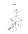
- FIG. 25 is a perspective view illustrating the table-type powder/granular material feeding device.
- the bottom 71a of the chute 71 is shaped like a round table.
- powder/granular material is agitated in the circumferential direction by the stirring part 72 that is called a vertical agitator.
- the stirring part 72 rotates about the shaft 71d that protrudes upward from the bottom 71a of the chute 71.
- Reference numeral 71b in FIG. 25 denotes a chute outlet for feeding powder/granular material to an outlet portion from the chute 71.
- the bottom 71a of the chute 71 can have a relatively large size, allowing a hopper (not shown) to have a large base area. Since the stirring part 72 including the vertical agitator can be provided, bridges can be effectively prevented. A joining area between the chute 71 and the hopper is inevitably circular, allowing the use of a clamp band similar to the clamp band 56 in FIG. 21 .
- the simple stirring part (agitator) 72 is necessary to prevent quite a large amount of the material from remaining on the bottom 71a shaped like a flat table. Also in the case of a powder material, the material is deposited and left in a gap between the stirring part 72 and the surface of the bottom 71a and on the blade of the stirring part 72. A screw 75 disposed directly under the bottom (table surface) 71a is laterally shifted so as to avoid a driving shaft that rotates the stirring part 72, limiting an area of feeding to the screw 75. Moreover, the stirring part 72 only passes above the screw, reducing the capability of filling to the screw 75.
- the screw 75 can be centered by providing another room under the bottom (table surface) 71a. Moreover, the provision of a stirring part (horizontal agitator) 73 around the screw 75 can improve the capability of filling to the screw 75, though a large amount of powder/granular material is left under the screw 75.
- FIGS. 22 , 23A, and 23B are a perspective view and side cross-sectional views of a powder/granular material feeding device 80 that includes the hopper 82 shaped like a square cylinder (that is, a rectangular prism) on the flexible chute 81.
- the side of the chute is deformed by a paddle 83 from the outside of the flexible chute 81 to move internal powder/granular material, thereby preventing bridges-
- powder/granular material having medium flowability e.g., calcium carbonate or talc is highly unlikely to cause bridges.
- the rectangular-prism hopper 82 can be more easily manufactured than a conical or pyramidal hopper in terms of the manufacturing cost, leading to lower manufacturing cost.
- the flexible chute type has a lower resistance than in the rotations of a stirring part acting as a rotating object in powder/granular material.
- the capacity of a motor for driving the stirring part can be reduced, achieving a clear cost advantage. Since the resistance is low, the flexible chute 81 can have a larger size, so that the hopper 82 can advantageously have a large capacity with relative ease.
- the flexible chute 81 is a consumable item that is an elastic body made of resin or the like.
- the flexible chute 81 needs replacing every several years (e.g., two years), requiring running cost for each replacement of the flexible chute 81.
- the paddle 83 desirably comes into contact with a flat surface, the flexible chute 81 and the hopper 82 have squares, which may lead to deposition of a material on the corners of the hopper 82 so as to cause bridges. In other words, the capability of preventing bridges is slightly lower than in the case where the hopper 82 has a circle.
- agitation by the paddle 83 does not generate a force pressing a material to the screw 84, so that the material is dropped and inserted to the screw 84 only by its own weight.
- the capability of filling a material to the screw 84 is lower than in internal agitation. Since the flexible chute 81 is vibrated by swinging of the paddle 83, the weight is likely to fluctuate. In the case where the amount of discharged powder/granular material is controlled during measurement, the feeding accuracy may decrease.
- the conventional powder/granular material feeding devices of any types have advantages and disadvantages. Any of the powder/granular material feeding devices does not fully satisfy the function of sufficiently preventing bridges and ratholes, the function of fully stabilizing the filling rate of the outlet portion with a sufficient area of feeding to the screw, and the function of suppressing the amount of remaining powder/granular material. Some of the powder/granular material feeding devices regularly require consumable items such as the flexible chute 81 or leave a large amount of powder/granular material in a specific area inside the chute.
- An object of the present invention is to provide a powder/granular material feeding device that fully satisfies the functions of sufficiently preventing bridges and ratholes and fully stabilizing the filling rate of an outlet portion without requiring consumable items such as a flexible chute or leaving a large amount of powder/granular material in a specific area inside the chute.
- a powder/granular material feeding device is characterized by including: a hopper that receives powder/granular material; an outlet portion that discharges powder/granular material; a chute that guides, into the outlet portion, powder/granular material dropped from the hopper; and a stirring part that rotates a stirring member about a shaft protruding so as to tilt diagonally upward from the lower part of the interior of the chute.
- the stirring member rotates about the shaft protruding so as to tilt diagonally upward from the lower part of the interior of the chute.
- powder/granular material is agitated diagonally, that is, in various directions such as a vertical direction and a circumferential direction by the stirring member of the stirring part.
- This configuration sufficiently agitates powder/granular material in the chute and the hopper, thereby preventing the occurrence of bridges and ratholes.
- the track of rotation of the stirring part can be located along the outlet portion, thereby fully stabilizing the filling rate of powder/granular material to the outlet portion.
- the stirring member rotating about the inclined shaft of the stirring part can reduce vertical motions of agitated powder/granular material and suppress fluctuations in weight as compared with a horizontal agitator including a stirring part that rotates in the vertical direction.
- the outlet portion preferably contains a screw.
- the powder/granular material feeding device of the present invention is characterized in that the shaft of the stirring part protrudes to the center of the interior of the chute in plan view. This configuration can sufficiently agitate powder/granular material over the entire interior of the chute.
- the chute preferably includes an inclined plane with an inner surface inclined diagonally upward, and the shaft is preferably protruded from the inclined plane.
- the chute and the stirring part can be disposed with a relatively simple configuration. Since the shaft of the stirring part is protruded perpendicularly to the inclined plane, the seal structure of the inclined plane of the chute and the shaft can be constructed with relative ease, minimizing an increase in manufacturing cost.
- the inclined plane of the chute is circular.
- the hopper is oval and has a constant cross-sectional shape in the vertical direction, that is, an oval cylinder, thereby minimizing the occurrence of bridges in the hopper without the need for a vertical agitator.
- the powder/granular material feeding device of the present invention is characterized in that the outlet portion includes a screw casing having an internal space, the internal space of the screw casing and the bottom space of the chute are linearly connected to each other, and the stirring member provided in the stirring part passes directly above the connected part of the spaces.
- the bottom of the chute and the screw casing are linearly connected, thereby increasing the dimensions of a feed opening to the screw.
- the stirring member passes directly above the overall feed opening to the screw while pressing powder/granular material. This configuration improves filling of powder/granular material into the screw casing, stably keeping a high filling rate.
- the powder/granular material feeding device is characterized by further including a driving force transmission mechanism that transmits the driving force of a motor to the screw provided in the outlet portion and the stirring part, wherein the outlet portion and the stirring part are driven through the driving force transmission mechanism.
- a driving force transmission mechanism that transmits the driving force of a motor to the screw provided in the outlet portion and the stirring part, wherein the outlet portion and the stirring part are driven through the driving force transmission mechanism.
- the powder/granular material feeding device of the present invention is characterized in that the chute includes the inclined plane with the inner surface inclined diagonally upward, a conical wall extended from the outer periphery of the inclined plane, and a side wall that connects the conical wall and the hopper to guide powder/granular material in the hopper to the conical wall of the chute.
- the side wall of the chute may be oval in plan view and may have a constant cross-sectional shape in the vertical direction.
- the side wall of the chute can have a relatively simple shape.
- the side wall of the chute may have a cross-sectional shape expanding in the lower part of the chute relative to the upper part.
- the side wall of the chute may have a circular upper end in plan view, and the hopper may be circular and have a constant cross-sectional shape in the vertical direction.
- the hopper can be circular.
- the hopper can be more easily formed than an oval hopper.
- the hopper and the chute can be easily connected with a simple structure while the hopper can be connected to other members with a simple structure.
- the stirring member of the stirring part rotates about the shaft protruding so as to incline diagonally upward from the lower part of the interior of the chute, thereby preventing the occurrence of bridges and ratholes. Furthermore, the filling rate of powder/granular material to the outlet portion can be sufficiently stabilized. Even in the case where powder/granular material is discharged during weight measurement, fluctuations in weight can be suppressed, achieving high feeding accuracy. Since the need for consumable items such as a flexible chute can be eliminated, only small maintenance cost is necessary. Moreover, the shaft protruding diagonally upward allows the stirring member, e.g., a stirring blade for agitation in the bottom of the chute to be sufficiently supported on the base of the shaft.
- the chute includes the inclined plane that is directed diagonally upward, and the shaft protruded from the inclined plane.
- the chute and the stirring part can be disposed with a relatively simple configuration.
- the seal structure of the inclined plane of the chute and the shaft can be constructed with relative ease, suppressing the manufacturing cost.
- the inclined plane of the chute is circular, powder/granular material can be sufficiently agitated and hardly remains near the joining area between the inclined plane and the side wall of the chute.
- the oval hopper has a constant cross-sectional shape in the vertical direction, thereby minimizing the occurrence of bridges in the hopper without the need for a vertical agitator.
- the internal space of the screw casing provided in the outlet portion and the bottom space of the chute are linearly connected to each other, and the stirring member provided in the stirring part passes directly above the connected part.
- the side wall of the chute has a cross-sectional shape expanding in the lower part of the chute relative to the upper part. This configuration can satisfactorily prevent powder/granular material deposition on the side wall of the chute, thereby reliably preventing the occurrence of bridges. Therefore, powder/granular material can be stably discharged from the powder/granular material feeding device, improving the feeding accuracy and reliability of the powder/granular material feeding device.
- the upper end of the side wall of the chute may be circular in plan view and the circular hopper may have a constant cross-sectional shape in the vertical direction.
- the hopper can be circular and thus can be more easily formed than an oval hopper.
- the hopper and the chute can be easily connected with a simple structure while the hopper can be connected to other members with a simple structure, thereby reducing the manufacturing cost.
- a powder/granular material feeding device according to embodiments of the present invention will be described below with reference to the accompanying drawings. These embodiments are merely exemplary and thus the present invention is not always limited to these embodiments.
- a direction along which powder/granular material is fed in an outlet portion will be referred to as a forward direction.
- a powder/granular material feeding device includes a hopper 1 that receives powder/granular material, an outlet portion 2 that discharges powder/granular material, a chute 3 that guides, to the outlet portion 2, powder/granular material dropped from the hopper 1, a stirring part 4 that rotates stirring members 4b about a shaft 4a protruding so as to incline diagonally upward from the lower part of the interior of the chute 3, a metering unit 5 loaded with these constituent elements, and a control unit (not shown).
- the top surface of the hopper 1 is covered with a lid, which is not illustrated. The lid is optionally connected to a powder/granular material feed pipe and so on.
- the hopper 1 and the upper part of the chute 3 are oval in plan view and have a constant cross-sectional shape in a vertical direction, that is, like an oval cylinder.
- an inclined plane 3a is formed with an inner surface inclined diagonally upward (that is, the inner surface inclined in the forward direction).
- the stirring part 4 rotates the stirring members 4b, which include stirring blades, about the shaft 4a.
- the shaft 4a of the stirring part 4 is extended perpendicularly to the inclined plane 3a from the inclined plane 3a and protrudes to the center of the interior of the chute 3 in plan view.
- the inclined plane 3a of the chute 3 has a round shape.
- the stirring members 4b of the stirring part 4 are respectively extended from two points: the proximal end and the leading end of the shaft 4a in the radial direction of the inclined plane 3a.
- the ends of the stirring members 4b are radially extended so as to incline along a conical wall 3b and the side wall 3c of the chute 3.
- the two stirring members 4b of the stirring part 4 are extended perpendicularly to each other in a direction perpendicular to the shaft 4a at angles differing from each other by 90 degrees each.
- the present invention is not limited to this configuration.
- the conical wall 3b of the chute 3 is conically extended forward, laterally, and upward from the inclined plane 3a.
- the ends of the stirring members 4b of the stirring part 4 are rotated along the inner surface of the conical wall 3b of the chute 3.
- the proximal ends of the stirring members 4b of the stirring part 4 are rotated along the inner surface of the inclined plane 3a of the chute 3.
- the lower end of the side wall 3c of the chute 3 is connected along the outer edge of the conical wall 3b of the chute 3.
- the side wall 3c of the chute 3 is oval in plan view and is vertically extended upward while keeping the shape of the lower end-
- the hopper 1 is identical in shape to the side wall 3c of the chute 3 in plan view and is extended upward.
- the upper end of the chute 3 and the lower end of the hopper 1 can be joined to each other with a clamp band 7, which is not illustrated.
- a gasket 8 is disposed between the upper end of the chute 3 and the lower end of the hopper 1.
- the outlet portion 2 is substantially cylindrical in longitudinal section or has a spectacle shape that is laterally extended.
- An outlet pipe 2a and a screw casing 2e which are longitudinally extended, contain a single rotatable screw 2b or double rotatable screws 2b (the single screw 2b in FIGS. 1 to 6 ).
- a longitudinally extended part of the conical wall 3b of the chute 3 and the upper edge of the screw casing 2e are linearly connected and opened.
- the screw casing 2e is filled with powder/granular material from the opening (also called a feed opening).
- the end of the outlet pipe 2a is connected to an exit pipe 2c that has an opening at the bottom. Powder/granular material delivered into the exit pipe 2c in the screw 2b is discharged downward (outside) from the exit pipe 2c.
- a motor 6 is provided diagonally at the rear of the chute 3 and a worm gear 6a is provided on the end of the drive shaft of the motor 6.
- the shaft 4a of the stirring part 4 is protruded diagonally downward from the outer surface of the inclined plane 3a of the chute 3.
- a stirring part gear 4c is attached to the end of a part protruding downward.
- the rear end of the shaft of the screw 2b is protruded from the rear end of the screw casing 2e.
- An outlet gear 2d is attached to the protruded part of the screw 2b.
- the stirring part gear 4c and the outlet gear 2d are engaged with the worm gear 6a attached to the end of the drive shaft of the motor 6.
- the motor 6 is driven to rotate the stirring members 4b of the stirring part 4 and the screw 2b of the outlet portion 2 through the stirring part gear 4c, the outlet gear 2d, and so on.
- the worm gear 6a attached to the motor 6 and the stirring part gear 4c and the outlet gear 2d that are engaged with the worm gear 6a constitute a driving force transmission mechanism that transmits the driving force of the motor 6 to the screw 2b and the stirring members 4b of the stirring part 4.
- the screw 2b of the outlet portion 2 and the stirring part 4 are driven through the driving force transmission mechanism.
- the constituent elements specifically, the hopper 1, the chute 3, the stirring part 4, and the outlet portion 2 are placed on the metering unit 5.
- the total weight of the constituent elements and powder/granular material is measured by the metering unit 5.
- the control unit (not shown) controls the rotation speed of the screw 2b so as to keep constant the weight of discharged powder/granular material (the amount of discharged powder/granular material) per hour or the weight of powder/granular material in each discharge.
- the motor 6 is driven to rotate the stirring members 4b of the stirring part 4, thereby agitating powder/granular material in the chute 3 and the lower part of the interior of the hopper 1.
- the powder/granular material is then introduced into the screw casing 2e from the lower part of the chute 3, is passed through the outlet pipe 2a by the screw 2b, and is discharged out of the exit pipe 2c.
- the stirring members 4b of the stirring part 4 rotate about the shaft 4a.
- the shaft 4a protrudes so as to incline diagonally upward from the lower part of the interior of the chute 3, achieving the advantages of a so-called horizontal agitator type and a table type.
- the shaft 4a of the stirring part 4 is disposed in an inclined position, powder/granular material can be sufficiently agitated by the stirring members 4b in various directions including the vertical direction and a circumferential direction.
- the hopper 1 has a constant cross-sectional shape, that is, a cylindrical shape in the vertical direction. Hence, the occurrence of bridges and ratholes in the chute 3 and the hopper 1 can be quite satisfactorily prevented.
- bridges and ratholes can be prevented.
- bridges and ratholes can be satisfactorily prevented for materials including titanium oxide that is likely to increase in adhesion and compressibility with low flowability. Furthermore, this configuration can eliminate the need for a vertical agitator and so on, thereby effectively preventing bridges and so on while suppressing an increase in manufacturing cost with high cleaning performance. This configuration can be reliably applied to most kinds of powder/granular material.
- the chute 3 and the outlet portion 2, specifically, the bottom of the chute 3 and the screw casing 2e are linearly connected (feed opening), thereby increasing the dimensions of the feed opening to the screw 2b.
- the stirring members 4b pass directly above the overall feed opening to the screw 2b while pressing powder/granular material. This configuration improves filling of powder/granular material into the screw casing 2e, stably keeping a high filling rate. Consequently, the stability of discharge and the feeding accuracy can be improved.
- this configuration hardly moves stirred powder/granular material in the vertical direction as compared with the stirring part of a horizontal agitator.
- fluctuations in weight can be suppressed to obtain a stable weight.
- the powder/granular material feeding device can be used for feeding a small amount of powder/granular material in an optimum condition.
- the powder/granular material feeding device is similar to the table-type powder/granular material feeding device in FIG. 20 in that the shaft is protruded from a surface near the bottom and rotor blades are provided to rotate about the shaft.
- the powder/granular material feeding device is different from the table-type powder/granular material feeding device in that the rotary stirring members 4b can scrape powder/granular material substantially over the inclined plane 3a and the conical wall 3b of the chute 3. Since a space in the screw casing 2e is directly connected to the conical wall 3b of the chute 3, only quite a small amount of powder/granular material is left on the inner surface of the conical wall 3b of the chute 3.
- the stirring members 4b rotating in a tilted state facilitate falling of powder/granular material, thereby preventing powder/granular material from partially remaining on the stirring members 4b.
- the chute 3 including the inclined plane 3a, the conical wall 3b, and the side wall 3c shaped like an oval cylinder can be manufactured by boiler making (also called a welded structure) without using molds.
- the chute 3 can be manufactured using molds. In this case, the manufacturing cost of the chute 3 can be reduced by high volume production.
- the rear of the lower part of the chute 3 is inclined as if the rear was cut in side view, thereby suppressing the length of the screw 2b.
- the end of the screw 2b does not always need to be supported.
- the manufacturing cost can be reduced by eliminating bearings.
- the screw 2b can be reduced in diameter, allowing the powder/granular material feeding device to be optimally used for feeding a small amount of powder/granular material.
- the screw 2b can be located at the center of the powder/granular material feeding device in front view-Hence, the inlet and the outlet for powder/granular material fed to the hopper 1 are located on the same straight line, allowing a user to easily create an installation plan of the powder/granular material feeding device with higher convenience.
- the shaft 4a protrudes diagonally upward from the inclined plane 3a near the bottom of the chute 3, allowing the stirring members 4b to be sufficiently supported and stably rotated on the base of the shaft 4a.
- the shaft may be protruded from above to the bottom of the chute 3 such that the stirring blades are fixed on the end of the shaft. In this case, however, the stirring blades attached to the end of the shaft may vibrate the end of the shaft during rotations and cause unstable rotations of the stirring blades.
- the stirring members 4b for agitation near the bottom of the chute 3 can be particularly sufficiently supported on the base of the shaft 4a, so that the stirring members 4b can be stably rotated.
- the shaft 4a of the stirring part 4 is protruded perpendicularly to the inclined plane 3a, thereby relatively easily constructing a seal structure of the inclined plane 3a of the chute 3 and the shaft 4a of the stirring part 4. This configuration can reduce the manufacturing cost.
- the inclined plane 3a of the chute 3 is inclined at 45° with respect to a horizontal line or the conveyance line of the screw 2b in side view, and the shaft 4a protrudes perpendicularly to the inclined plane 3a.
- the stirring members 4b can sufficiently agitate powder/granular material in the vertical direction and particularly, in the circumferential direction.
- the inclination angle of the inclined plane 3a is not limited to 45°. As illustrated in FIGS.
- a shaft 4a may be inclined at more than 45°, for example, 60° with respect to a horizontal line or may be inclined at less than 45°, for example, 30° (not shown) with respect to the horizontal line (a powder/granular material feeding device according to a second embodiment of the present invention).
- the relatively large inclined plane 3a is formed in the rear of the lower part of the chute 3.
- the present invention is not limited to this configuration.
- a shaft 4a may protrude diagonally upward substantially from a corner in the rear of the lower part of a chute 3 such that stirring members 4b rotate about the shaft 4a along a conical wall 3b of the chute (a powder/granular material feeding device according to a third embodiment of the present invention).
- the stirring members 4b of the stirring part 4 are extended from two points: the base and end of the shaft 4a.
- the present invention is not limited to this configuration.
- the stirring members 4b may be extended to two sides from a point of the shaft 4a.
- a shaft 4a may be further protruded upward with stirring members 4b provided at three points (or at least three points).
- the stirring members 4b are extended in the radial direction.
- the present invention is not limited to this configuration.
- the stirring members 4b provided at any intervals in a circumferential direction may be extended in multiple directions (at least three directions, a powder/granular material feeding device according to a fourth embodiment of the present invention).
- the driving force transmission mechanism including the worm gear 6a, the stirring part gear 4c, and the outlet gear 2d is provided to transmit the driving force of the single motor 6 to the screw 2b of the outlet portion 2 and the stirring part 4.
- the screw 2b of the outlet portion 2 and the stirring part 4 are driven through the driving force transmission mechanism.
- a motor 11 for rotating a screw 2b of an outlet portion 2 and a motor 12 for rotating a stirring part 4 may be separately provided (a powder/granular material feeding device according to a fifth embodiment of the present invention).
- the number of motors 11 and 12 leads to higher manufacturing cost.
- the screw 2b of the outlet portion 2 and the stirring part 4 can be separately driven or controlled with different adjusted rotation speeds.
- FIGS. 14 to 18 illustrate a powder/granular material feeding device according to a sixth embodiment of the present invention.
- a side wall 3c of a chute 3 in the powder/granular material feeding device expands in the lower part of the chute in cross section relative to the upper part.
- the left side wall 3c and the right side wall 3c of the chute 3 expand in the lower part of the chute in front view.
- the side wall 3c on the front end and the side wall 3c on the rear end are formed like vertical straight lines in side view.
- the side walls 3c are seamlessly connected in circumferential and vertical directions.
- the upper end of the side wall 3c of the chute 3 is circular in plan view (perfect circle) and a hopper 1 is a cylinder (perfect circle) as large as the upper end of the side wall 3c of the chute 3.
- the hopper 1 has a constant cross-sectional shape in the vertical direction.
- the side wall 3c of the chute 3 expands in the lower part of the chute in cross section relative to the upper part.
- powder/granular material introduced from the hopper 1 into the chute 3 is hardly compressed, so that a pressure on the side wall 3c of the chute 3 decreases and powder/granular material deposited on the side wall 3c is likely to fall off the side wall 3c by its own weight.
- This configuration can satisfactorily prevent powder/granular material deposition on the side wall 3c of the chute 3. Since the hopper 1 and the upper end of the chute 3 are circular in plan view, a degree of curving is kept constant but is not locally increased unlike in the case of an oval shape in plan view, thereby satisfactorily preventing powder/granular material deposition on the side wall 3c of the chute 3.
- This configuration can prevent the occurrence of bridges in the chute 3 with higher reliability, stabilize the weight of powder/granular material discharged from the powder/granular material feeding device, and stabilize the rate of filling into a screw 2b of an outlet portion 2 provided under the chute 3, thereby improving the accuracy of feeding and reliability of the powder/granular material feeding device.
- the hopper 1 and the upper end of the chute 3 are circular in plan view.
- the hopper 1 can be more easily formed than the oval hopper 1.
- the hopper 1 and the chute 3 can be connected to each other with a simple structure, and the hopper can be also connected to other members with a simple structure, thereby reducing the manufacturing cost.
- the powder/granular material feeding device is a screw feeder including the screw 2b provided in the outlet portion 2.
- the present invention is not limited to this configuration.
- the outlet portion 2 may be a feeder device including a belt-type feeder 13 (a powder/granular material feeding device according to a seventh embodiment of the present invention).
- the present invention is also applicable to a powder/granular material feeding device including an outlet portion with an on-off valve.
Landscapes
- Engineering & Computer Science (AREA)
- Mechanical Engineering (AREA)
- Life Sciences & Earth Sciences (AREA)
- Environmental Sciences (AREA)
- Birds (AREA)
- Animal Husbandry (AREA)
- Biodiversity & Conservation Biology (AREA)
- Filling Or Emptying Of Bunkers, Hoppers, And Tanks (AREA)
- Auxiliary Methods And Devices For Loading And Unloading (AREA)
Abstract
Description
- The present invention relates to powder/granular material feeding devices, and particularly relates to a powder/granular material feeding device suitable for quantitative feeding of powder/granular material.
- Powder/granular material feeding devices, also called feeders, have been widely known as devices for quantitative feeding of powder/granular material. As illustrated in
FIGS. 20 and21 , such a powder/granular material feeding device includes ahopper 51 that receives powder/granular material, anoutlet portion 52 havingscrews 52a for discharging powder/granular material, achute 53 that guides, into theoutlet portion 52, powder/granular material dropped from thehopper 51, and astirring device 54 that is also called an agitator for agitating powder/granular material in thechute 53 and thehopper 51. The powder/granular material feeding device for quantitative feeding of powder/granular material includes, in addition to these constituent elements (thehopper 51, theoutlet portion 52, thechute 53, and the stirring device 54), ametering unit 55 on which these constituent elements are loaded, and a control unit (not shown) that controls theoutlet portion 52 so as to keep constant the weight of discharged powder/granular material (the amount of discharged powder/granular material) per hour or the weight of powder/granular material in each discharge. - Various kinds of powder/granular material feeding devices are available. The
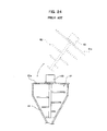
hopper 51 inFIGS. 20 and21 is a cylinder that is vertically extended with a constant shape in cross section. Ahopper 82 inFIGS. 22 ,23A, and 23B is shaped like a rectangular prism. Ahopper 61 inFIG. 24 has a curved shape, e.g., a conical or pyramidal shape expanding upward in cross section. As simply illustrated inFIG. 24 , thecurved hopper 61 expands upward in cross section and can be advantageously reduced in height with a sufficient capacity. However, thehopper 61 with a curved wall surface decreases in cross-sectional area toward the bottom of thehopper 61, causing bridging, that is, partially or entirely remaining powder/granular material with high adhesion and compressibility or a rathole that is a central hole of a material. These phenomena are effectively avoided by adopting a cylindrical hopper or hanging, as illustrated inFIG. 24 , a vertical agitator (stirring part) 62 downward into thehopper 61 from the top surface of thehopper 61. A hopper agitator including such a vertical agitator is disclosed in, for example, Japanese Patent Laid-Open No-9-216688 - Unfortunately, the provision of the
vertical agitator 62 requires a space for lifting theagitator 62 during cleaning of the hopper 61 (thehopper 61 is always cleaned each time a powder/granular material type is changed). Furthermore, atop surface 61a of thehopper 61 needs to be lifted with an additional weight of theagitator 62 and anelectric motor 63 for driving the agitator, reducing workability of cleaning and so on. For this reason, the agitator in general is not so popular among users. - The chute provided under the hopper contains the stirring device that is a mechanism for agitating powder/granular material in the hopper on the chute to prevent bridges in the hopper. A typical stirring device is, as illustrated in
FIGS. 20 and21 , a horizontal agitator that has a stirring part (agitator) 54b for vertically agitating powder/granular material with respect to ashaft 54a protruding from the side of thechute 53. Furthermore, as illustrated inFIG. 25 , a table-type powder/granular material feeding device is available that rotates powder/granular material in a circumferential direction by means of a stirringpart 72 that is called a vertical agitator. The stirringpart 72 rotates about ashaft 71d protruding upward from abottom 71a of achute 71. Moreover, as illustrated inFIGS. 22 ,23A, and 23B , a powder/granular material feeding device of flexible chute type is available in which achute 81 disposed under thehopper 82 is made of flexible resin and is deformed from the outside so as to move an internal material. - The stirring device (stirring part) also supplies powder/granular material into an outlet portion provided under the stirring device and stabilizes the powder/granular material with a high filling rate in the outlet portion. The stable filling rate in the outlet portion remarkably contributes to more stable discharging capability and higher feeding accuracy (small variations).
- The outlet portion is a screw-type outlet (double screws or a single screw) using the
screws 52a and ascrew 84 illustrated inFIGS. 21 to 23B . The outlet portion may be vibration type, belt type, disk type, and so on. However, the screw type is the most suitable for powder/granular materials having various properties, e.g., adhesion and discharge. The single screw 84 (seeFIGS. 22 ,23A, and 23B ) is preferably used for a less adhesive material, whereas thedouble screws 52a (seeFIG. 21 ) capable of self-cleaning is preferably used for a highly adhesive material. The double screws capable of offsetting screw pulsations are frequently used for high feeding accuracy. - Hence, the stirring part of the stirring device disposed in the chute has the function of feeding a material to the screw acting as the outlet portion under the hopper as well as the function of preventing bridges in the hopper disposed on the chute. The stirring part is a mechanism that plays a key role in the powder/granular material feeding device and is quite important in determining the performance and character of the powder/granular material feeding device.
- The conventionally used powder/granular material feeding devices of the respective types and the advantages and disadvantages thereof will be specifically described below.
-
FIGS. 20 ,21 , and26 illustrate the powder/granular material feeding devices, each having the horizontal stirring part called a horizontal agitator. The two types of powder/granular material feeding devices have the dome-shaped chute 53 inFIGS. 20 and21 and asquare chute 91 inFIG. 26 . The rectangular-prism chute 91 inFIG. 26 can be produced by boiler making (also called a welded structure). Ascrew 92a with a flat driving side and a flat discharging side allows the opening of thechute 91 to have a relatively simple sealing structure that advantageously facilitates sealing. Moreover, the rectangular-prism chute 91 and ascrew casing 92b that accommodates the screws (outlet portion) 92a are linearly in contact with each other, forming a long area of feeding to thescrews 92a. Thus, the powder/granular material feeding device including the rectangular-prism chute 91 can feed a material that is hard to come into thescrews 92a, for example, a film material. - However, a powder/granular
material feeding device 90 disadvantageously requires welding over the corners of thechute 91, is likely to deposit or leave a material on the corners of thechute 91, and increases a screw length as compared with the dome-shaped chute 53 (seeFIG. 21 ), forming a dual support structure. Moreover, a hopper (not shown) disposed on the rectangular-prism chute 91 is inevitably shaped like a rectangular prism, so that thechute 91 and the hopper need to be joined with clamps at several points. Disadvantageously, the attachment and detachment of the hopper requires considerable effort and time as compared with the dome-shaped chute.Reference numeral 93 inFIG. 26 denotes the stirring part of the horizontal agitator. - The powder/granular material feeding device with the dome-
shaped chute 53 inFIGS. 20 and21 has no corners on thechute 53, which reduces powder/granular material deposition and residue and facilitates cleaning. Thecylindrical hopper 51 that hardly allows powder/granular material deposition is attached on the upper part of thechute 53, and aclamp band 56 can be used on a joining area between thechute 53 and thehopper 51. Advantageously, thehopper 51 can be attached and detached with less effort and time. - However, the dome-
shaped chute 53 provided in the powder/granular material feeding device disadvantageously needs to be manufactured with a mold, for example, by drawing or a lost-wax process, so that the dome-shaped chute 53 and ascrew casing 52b that accommodates thescrews 52a are joined with a slightly complicated configuration. Furthermore, the stirring part (agitator) 54b approaches closest to thescrews 52a only at a center point. A space is formed between an agitation range and thescrews 52a, and powder/granular material is fed to thescrews 52a with a shorter feeding area as compared with the rectangular-prism chute, so that the powder/granular material is less supplied to thescrews 52a than in the rectangular-prism chute. - The powder/granular material feeding device having the horizontal agitator vertically agitates powder/granular material by means of the stirring
part -
FIG. 25 is a perspective view illustrating the table-type powder/granular material feeding device. In such a powder/granular material feeding device, thebottom 71a of thechute 71 is shaped like a round table. As has been discussed, powder/granular material is agitated in the circumferential direction by thestirring part 72 that is called a vertical agitator. The stirringpart 72 rotates about theshaft 71d that protrudes upward from thebottom 71a of thechute 71.Reference numeral 71b inFIG. 25 denotes a chute outlet for feeding powder/granular material to an outlet portion from thechute 71. In such a so called table-type powder/granular material feeding device, thebottom 71a of thechute 71 can have a relatively large size, allowing a hopper (not shown) to have a large base area. Since the stirringpart 72 including the vertical agitator can be provided, bridges can be effectively prevented. A joining area between thechute 71 and the hopper is inevitably circular, allowing the use of a clamp band similar to theclamp band 56 inFIG. 21 . - Even in the case of a granular material, e.g., a pellet that does not need agitation, the simple stirring part (agitator) 72 is necessary to prevent quite a large amount of the material from remaining on the
bottom 71a shaped like a flat table. Also in the case of a powder material, the material is deposited and left in a gap between thestirring part 72 and the surface of thebottom 71a and on the blade of thestirring part 72. Ascrew 75 disposed directly under the bottom (table surface) 71a is laterally shifted so as to avoid a driving shaft that rotates thestirring part 72, limiting an area of feeding to thescrew 75. Moreover, thestirring part 72 only passes above the screw, reducing the capability of filling to thescrew 75. - The
screw 75 can be centered by providing another room under the bottom (table surface) 71a. Moreover, the provision of a stirring part (horizontal agitator) 73 around thescrew 75 can improve the capability of filling to thescrew 75, though a large amount of powder/granular material is left under thescrew 75. -
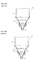
FIGS. 22 ,23A, and 23B are a perspective view and side cross-sectional views of a powder/granularmaterial feeding device 80 that includes thehopper 82 shaped like a square cylinder (that is, a rectangular prism) on theflexible chute 81. The side of the chute is deformed by apaddle 83 from the outside of theflexible chute 81 to move internal powder/granular material, thereby preventing bridges- In the case of the rectangular-prism hopper 82, powder/granular material having medium flowability, e.g., calcium carbonate or talc is highly unlikely to cause bridges. The rectangular-prism hopper 82 can be more easily manufactured than a conical or pyramidal hopper in terms of the manufacturing cost, leading to lower manufacturing cost. Furthermore, the flexible chute type has a lower resistance than in the rotations of a stirring part acting as a rotating object in powder/granular material. Thus, the capacity of a motor for driving the stirring part can be reduced, achieving a clear cost advantage. Since the resistance is low, theflexible chute 81 can have a larger size, so that thehopper 82 can advantageously have a large capacity with relative ease. - In the powder/granular
material feeding device 80 including theflexible chute 81, however, theflexible chute 81 is a consumable item that is an elastic body made of resin or the like. Thus, theflexible chute 81 needs replacing every several years (e.g., two years), requiring running cost for each replacement of theflexible chute 81. Since thepaddle 83 desirably comes into contact with a flat surface, theflexible chute 81 and thehopper 82 have squares, which may lead to deposition of a material on the corners of thehopper 82 so as to cause bridges. In other words, the capability of preventing bridges is slightly lower than in the case where thehopper 82 has a circle. Moreover, agitation by thepaddle 83 does not generate a force pressing a material to thescrew 84, so that the material is dropped and inserted to thescrew 84 only by its own weight. Thus, the capability of filling a material to thescrew 84 is lower than in internal agitation. Since theflexible chute 81 is vibrated by swinging of thepaddle 83, the weight is likely to fluctuate. In the case where the amount of discharged powder/granular material is controlled during measurement, the feeding accuracy may decrease. - As has been discussed, the conventional powder/granular material feeding devices of any types have advantages and disadvantages. Any of the powder/granular material feeding devices does not fully satisfy the function of sufficiently preventing bridges and ratholes, the function of fully stabilizing the filling rate of the outlet portion with a sufficient area of feeding to the screw, and the function of suppressing the amount of remaining powder/granular material. Some of the powder/granular material feeding devices regularly require consumable items such as the
flexible chute 81 or leave a large amount of powder/granular material in a specific area inside the chute. - The present invention has been devised to solve the problems. An object of the present invention is to provide a powder/granular material feeding device that fully satisfies the functions of sufficiently preventing bridges and ratholes and fully stabilizing the filling rate of an outlet portion without requiring consumable items such as a flexible chute or leaving a large amount of powder/granular material in a specific area inside the chute.
- In order to solve the problems, a powder/granular material feeding device according to the present invention is characterized by including: a hopper that receives powder/granular material; an outlet portion that discharges powder/granular material; a chute that guides, into the outlet portion, powder/granular material dropped from the hopper; and a stirring part that rotates a stirring member about a shaft protruding so as to tilt diagonally upward from the lower part of the interior of the chute.
- With this configuration, the stirring member rotates about the shaft protruding so as to tilt diagonally upward from the lower part of the interior of the chute. Thus, powder/granular material is agitated diagonally, that is, in various directions such as a vertical direction and a circumferential direction by the stirring member of the stirring part. This configuration sufficiently agitates powder/granular material in the chute and the hopper, thereby preventing the occurrence of bridges and ratholes. Moreover, the track of rotation of the stirring part can be located along the outlet portion, thereby fully stabilizing the filling rate of powder/granular material to the outlet portion. Furthermore, in the case of weight measurement of powder/granular material being discharged, the stirring member rotating about the inclined shaft of the stirring part can reduce vertical motions of agitated powder/granular material and suppress fluctuations in weight as compared with a horizontal agitator including a stirring part that rotates in the vertical direction. The outlet portion preferably contains a screw.
- Furthermore, the powder/granular material feeding device of the present invention is characterized in that the shaft of the stirring part protrudes to the center of the interior of the chute in plan view. This configuration can sufficiently agitate powder/granular material over the entire interior of the chute.
- Moreover, according to the powder/granular material feeding device of the present invention the chute preferably includes an inclined plane with an inner surface inclined diagonally upward, and the shaft is preferably protruded from the inclined plane. Hence, the chute and the stirring part can be disposed with a relatively simple configuration. Since the shaft of the stirring part is protruded perpendicularly to the inclined plane, the seal structure of the inclined plane of the chute and the shaft can be constructed with relative ease, minimizing an increase in manufacturing cost.
- Preferably, the inclined plane of the chute is circular. With this configuration, powder/granular material can be sufficiently agitated and hardly remains near a joining area between the inclined plane and the side wall of the chute. Moreover, the hopper is oval and has a constant cross-sectional shape in the vertical direction, that is, an oval cylinder, thereby minimizing the occurrence of bridges in the hopper without the need for a vertical agitator.
- Furthermore, the powder/granular material feeding device of the present invention is characterized in that the outlet portion includes a screw casing having an internal space, the internal space of the screw casing and the bottom space of the chute are linearly connected to each other, and the stirring member provided in the stirring part passes directly above the connected part of the spaces. With this configuration, the bottom of the chute and the screw casing are linearly connected, thereby increasing the dimensions of a feed opening to the screw. Moreover, the stirring member passes directly above the overall feed opening to the screw while pressing powder/granular material. This configuration improves filling of powder/granular material into the screw casing, stably keeping a high filling rate.
- The powder/granular material feeding device according to the present invention is characterized by further including a driving force transmission mechanism that transmits the driving force of a motor to the screw provided in the outlet portion and the stirring part, wherein the outlet portion and the stirring part are driven through the driving force transmission mechanism. This configuration can reduce the number of motors as compared with the case where motors are used respectively for the screw and the stirring part, achieving lower manufacturing cost.
- Furthermore, the powder/granular material feeding device of the present invention is characterized in that the chute includes the inclined plane with the inner surface inclined diagonally upward, a conical wall extended from the outer periphery of the inclined plane, and a side wall that connects the conical wall and the hopper to guide powder/granular material in the hopper to the conical wall of the chute.
- In this case, the side wall of the chute may be oval in plan view and may have a constant cross-sectional shape in the vertical direction. With this configuration, the side wall of the chute can have a relatively simple shape.
- The side wall of the chute may have a cross-sectional shape expanding in the lower part of the chute relative to the upper part. With this configuration, powder/granular material introduced from the hopper into the chute is hardly compressed, so that a pressure on the side wall of the chute decreases and powder/granular material deposited on the side wall is likely to fall off the side wall by its own weight. This can reliably prevent bridges caused by powder/granular material deposition on the side wall of the chute.
- In this case, the side wall of the chute may have a circular upper end in plan view, and the hopper may be circular and have a constant cross-sectional shape in the vertical direction. With this configuration, the hopper can be circular. The hopper can be more easily formed than an oval hopper. Furthermore, the hopper and the chute can be easily connected with a simple structure while the hopper can be connected to other members with a simple structure.
- According to the present invention, the stirring member of the stirring part rotates about the shaft protruding so as to incline diagonally upward from the lower part of the interior of the chute, thereby preventing the occurrence of bridges and ratholes. Furthermore, the filling rate of powder/granular material to the outlet portion can be sufficiently stabilized. Even in the case where powder/granular material is discharged during weight measurement, fluctuations in weight can be suppressed, achieving high feeding accuracy. Since the need for consumable items such as a flexible chute can be eliminated, only small maintenance cost is necessary. Moreover, the shaft protruding diagonally upward allows the stirring member, e.g., a stirring blade for agitation in the bottom of the chute to be sufficiently supported on the base of the shaft.
- Furthermore, the chute includes the inclined plane that is directed diagonally upward, and the shaft protruded from the inclined plane. Thus, the chute and the stirring part can be disposed with a relatively simple configuration. Moreover, the seal structure of the inclined plane of the chute and the shaft can be constructed with relative ease, suppressing the manufacturing cost.
- Since the inclined plane of the chute is circular, powder/granular material can be sufficiently agitated and hardly remains near the joining area between the inclined plane and the side wall of the chute. Moreover, the oval hopper has a constant cross-sectional shape in the vertical direction, thereby minimizing the occurrence of bridges in the hopper without the need for a vertical agitator.
- Furthermore, the internal space of the screw casing provided in the outlet portion and the bottom space of the chute are linearly connected to each other, and the stirring member provided in the stirring part passes directly above the connected part. This configuration improves filling of powder/granular material into the screw casing, stably keeping a high filling rate. Consequently, the stability of discharge and the feeding accuracy can be improved.
- The side wall of the chute has a cross-sectional shape expanding in the lower part of the chute relative to the upper part. This configuration can satisfactorily prevent powder/granular material deposition on the side wall of the chute, thereby reliably preventing the occurrence of bridges. Therefore, powder/granular material can be stably discharged from the powder/granular material feeding device, improving the feeding accuracy and reliability of the powder/granular material feeding device.
- In this case, the upper end of the side wall of the chute may be circular in plan view and the circular hopper may have a constant cross-sectional shape in the vertical direction. With this configuration, the hopper can be circular and thus can be more easily formed than an oval hopper. Furthermore, the hopper and the chute can be easily connected with a simple structure while the hopper can be connected to other members with a simple structure, thereby reducing the manufacturing cost.
-
-
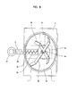
FIG. 1 is a front view illustrating a powder/granular material feeding device according to a first embodiment of the present invention; -
FIG. 2 is a partial cutaway longitudinal side view of the powder/granular material feeding device; -
FIG. 3 is a plan view of the powder/granular material feeding device; -
FIG. 4 is a perspective view of the powder/granular material feeding device viewed diagonally from the front; -
FIG. 5 is a perspective view of the powder/granular material feeding device viewed diagonally from the rear; -
FIG. 6 is a front view illustrating a powder/granular material feeding device according to a second embodiment of the present invention; -
FIG. 7 is a partial cutaway longitudinal side view of the powder/granular material feeding device; -
FIG. 8 is a plan view of the powder/granular material feeding device; -
FIG. 9 is a partial cutaway longitudinal side view illustrating a powder/granular material feeding device according to a third embodiment of the present invention; -
FIG. 10 is a front view illustrating a powder/granular material feeding device according to a fourth embodiment of the present invention; -
FIG. 11 is a partial cutaway longitudinal side view of the powder/granular material feeding device; -
FIG. 12 is a perspective view illustrating double screws and so on; -
FIG. 13 is a partial cutaway longitudinal side view illustrating a powder/granular material feeding device according to a fifth embodiment of the present invention; -
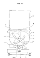
FIG. 14 is a front view illustrating a powder/granular material feeding device according to a sixth embodiment of the present invention; -
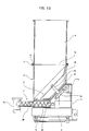
FIG. 15 is a partial cutaway longitudinal side view of the powder/granular material feeding device; -
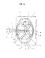
FIG. 16 is a plan view of the powder/granular material feeding device; -
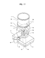
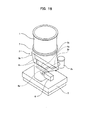
FIG. 17 is a perspective view of the powder/granular material feeding device viewed diagonally from the front; -
FIG. 18 is a perspective view of the powder/granular material feeding device viewed diagonally from the rear; -
FIG. 19 is a partial cutaway side view illustrating a powder/granular material feeding device according to a seventh embodiment of the present invention; -
FIG. 20 is a perspective view illustrating a conventional powder/granular material feeding device including a cylindrical hopper and a horizontal agitator (stirring part); -
FIG. 21 is an exploded perspective view of the conventional powder/granular material feeding device; -
FIG. 22 is an exploded perspective view illustrating another conventional powder/granular material feeding device including a rectangular-prism hopper and a flexible chute; -
FIG. 23A is a longitudinal section of the other conventional powder/granular material feeding device; -
FIG. 23B is a longitudinal section of the other conventional powder/granular material feeding device; -
FIG. 24 is a longitudinal section illustrating a conventional hopper agitator including a hopper and a vertical agitator (stirring part), the hopper being inclined so as to expand upward in cross section; -
FIG. 25 is a partially exploded perspective view illustrating the principle part of a conventional table-type powder/granular material feeding device; and -
FIG. 26 is a perspective view illustrating a conventional powder/granular material feeding device including a rectangular-prism hopper and a horizontal agitator (stirring part). - A powder/granular material feeding device according to embodiments of the present invention will be described below with reference to the accompanying drawings. These embodiments are merely exemplary and thus the present invention is not always limited to these embodiments. In the following explanation, a direction along which powder/granular material is fed in an outlet portion will be referred to as a forward direction.
- As illustrated in
FIGS. 1 to 5 , a powder/granular material feeding device according to a first embodiment of the present invention includes ahopper 1 that receives powder/granular material, anoutlet portion 2 that discharges powder/granular material, achute 3 that guides, to theoutlet portion 2, powder/granular material dropped from thehopper 1, astirring part 4 that rotates stirringmembers 4b about ashaft 4a protruding so as to incline diagonally upward from the lower part of the interior of thechute 3, ametering unit 5 loaded with these constituent elements, and a control unit (not shown). Moreover, the top surface of thehopper 1 is covered with a lid, which is not illustrated. The lid is optionally connected to a powder/granular material feed pipe and so on. - The
hopper 1 and the upper part of the chute 3 (aside wall 3c of the chute 3) are oval in plan view and have a constant cross-sectional shape in a vertical direction, that is, like an oval cylinder. Particularly, on the rear side of thechute 3, aninclined plane 3a is formed with an inner surface inclined diagonally upward (that is, the inner surface inclined in the forward direction). Thestirring part 4 rotates the stirringmembers 4b, which include stirring blades, about theshaft 4a. In the present embodiment, theshaft 4a of thestirring part 4 is extended perpendicularly to theinclined plane 3a from theinclined plane 3a and protrudes to the center of the interior of thechute 3 in plan view. - The
inclined plane 3a of thechute 3 has a round shape. In the present embodiment, the stirringmembers 4b of thestirring part 4 are respectively extended from two points: the proximal end and the leading end of theshaft 4a in the radial direction of theinclined plane 3a. Moreover, the ends of the stirringmembers 4b are radially extended so as to incline along aconical wall 3b and theside wall 3c of thechute 3. In the present embodiment, the two stirringmembers 4b of thestirring part 4 are extended perpendicularly to each other in a direction perpendicular to theshaft 4a at angles differing from each other by 90 degrees each. The present invention is not limited to this configuration. - The
conical wall 3b of thechute 3 is conically extended forward, laterally, and upward from theinclined plane 3a. The ends of the stirringmembers 4b of thestirring part 4 are rotated along the inner surface of theconical wall 3b of thechute 3. The proximal ends of the stirringmembers 4b of thestirring part 4 are rotated along the inner surface of theinclined plane 3a of thechute 3. The lower end of theside wall 3c of thechute 3 is connected along the outer edge of theconical wall 3b of thechute 3. Theside wall 3c of thechute 3 is oval in plan view and is vertically extended upward while keeping the shape of the lower end- Thehopper 1 is identical in shape to theside wall 3c of thechute 3 in plan view and is extended upward. The upper end of thechute 3 and the lower end of thehopper 1 can be joined to each other with aclamp band 7, which is not illustrated. Moreover, agasket 8 is disposed between the upper end of thechute 3 and the lower end of thehopper 1. - The
outlet portion 2 is substantially cylindrical in longitudinal section or has a spectacle shape that is laterally extended. Anoutlet pipe 2a and ascrew casing 2e, which are longitudinally extended, contain a singlerotatable screw 2b or doublerotatable screws 2b (thesingle screw 2b inFIGS. 1 to 6 ). A longitudinally extended part of theconical wall 3b of thechute 3 and the upper edge of thescrew casing 2e are linearly connected and opened. Thescrew casing 2e is filled with powder/granular material from the opening (also called a feed opening). The end of theoutlet pipe 2a is connected to anexit pipe 2c that has an opening at the bottom. Powder/granular material delivered into theexit pipe 2c in thescrew 2b is discharged downward (outside) from theexit pipe 2c. - In the present embodiment, a
motor 6 is provided diagonally at the rear of thechute 3 and aworm gear 6a is provided on the end of the drive shaft of themotor 6. Theshaft 4a of thestirring part 4 is protruded diagonally downward from the outer surface of theinclined plane 3a of thechute 3. A stirringpart gear 4c is attached to the end of a part protruding downward. Furthermore, the rear end of the shaft of thescrew 2b is protruded from the rear end of thescrew casing 2e. Anoutlet gear 2d is attached to the protruded part of thescrew 2b. The stirringpart gear 4c and theoutlet gear 2d are engaged with theworm gear 6a attached to the end of the drive shaft of themotor 6. Thus, themotor 6 is driven to rotate the stirringmembers 4b of thestirring part 4 and thescrew 2b of theoutlet portion 2 through thestirring part gear 4c, theoutlet gear 2d, and so on. In other words, in the present embodiment, theworm gear 6a attached to themotor 6 and thestirring part gear 4c and theoutlet gear 2d that are engaged with theworm gear 6a constitute a driving force transmission mechanism that transmits the driving force of themotor 6 to thescrew 2b and the stirringmembers 4b of thestirring part 4. Thescrew 2b of theoutlet portion 2 and thestirring part 4 are driven through the driving force transmission mechanism. - The constituent elements, specifically, the
hopper 1, thechute 3, the stirringpart 4, and theoutlet portion 2 are placed on themetering unit 5. The total weight of the constituent elements and powder/granular material is measured by themetering unit 5. The control unit (not shown) controls the rotation speed of thescrew 2b so as to keep constant the weight of discharged powder/granular material (the amount of discharged powder/granular material) per hour or the weight of powder/granular material in each discharge. - In this configuration, the
motor 6 is driven to rotate the stirringmembers 4b of thestirring part 4, thereby agitating powder/granular material in thechute 3 and the lower part of the interior of thehopper 1. The powder/granular material is then introduced into thescrew casing 2e from the lower part of thechute 3, is passed through theoutlet pipe 2a by thescrew 2b, and is discharged out of theexit pipe 2c. - In this case, the stirring
members 4b of thestirring part 4 rotate about theshaft 4a. Theshaft 4a protrudes so as to incline diagonally upward from the lower part of the interior of thechute 3, achieving the advantages of a so-called horizontal agitator type and a table type. - Since the
shaft 4a of thestirring part 4 is disposed in an inclined position, powder/granular material can be sufficiently agitated by the stirringmembers 4b in various directions including the vertical direction and a circumferential direction. Moreover, thehopper 1 has a constant cross-sectional shape, that is, a cylindrical shape in the vertical direction. Hence, the occurrence of bridges and ratholes in thechute 3 and thehopper 1 can be quite satisfactorily prevented. Thus, in the case of calcium carbonate or talc powder/granular material with medium flowability as well as pellet or glass fiber powder/granular material with high flowability, bridges and ratholes can be prevented. Moreover, bridges and ratholes can be satisfactorily prevented for materials including titanium oxide that is likely to increase in adhesion and compressibility with low flowability. Furthermore, this configuration can eliminate the need for a vertical agitator and so on, thereby effectively preventing bridges and so on while suppressing an increase in manufacturing cost with high cleaning performance. This configuration can be reliably applied to most kinds of powder/granular material. - The
chute 3 and theoutlet portion 2, specifically, the bottom of thechute 3 and thescrew casing 2e are linearly connected (feed opening), thereby increasing the dimensions of the feed opening to thescrew 2b. Moreover, the stirringmembers 4b pass directly above the overall feed opening to thescrew 2b while pressing powder/granular material. This configuration improves filling of powder/granular material into thescrew casing 2e, stably keeping a high filling rate. Consequently, the stability of discharge and the feeding accuracy can be improved. - Moreover, this configuration hardly moves stirred powder/granular material in the vertical direction as compared with the stirring part of a horizontal agitator. Thus, fluctuations in weight can be suppressed to obtain a stable weight. This stabilizes the control state of the powder/granular material feeding device that controls a weight being measured, achieving high feeding accuracy. Thus, the powder/granular material feeding device can be used for feeding a small amount of powder/granular material in an optimum condition.
- The powder/granular material feeding device is similar to the table-type powder/granular material feeding device in
FIG. 20 in that the shaft is protruded from a surface near the bottom and rotor blades are provided to rotate about the shaft. However, the powder/granular material feeding device is different from the table-type powder/granular material feeding device in that therotary stirring members 4b can scrape powder/granular material substantially over theinclined plane 3a and theconical wall 3b of thechute 3. Since a space in thescrew casing 2e is directly connected to theconical wall 3b of thechute 3, only quite a small amount of powder/granular material is left on the inner surface of theconical wall 3b of thechute 3. Even in the case where powder/granular material is deposited on, for example, the stirringmembers 4b, the stirringmembers 4b rotating in a tilted state facilitate falling of powder/granular material, thereby preventing powder/granular material from partially remaining on the stirringmembers 4b. - The
chute 3 including theinclined plane 3a, theconical wall 3b, and theside wall 3c shaped like an oval cylinder can be manufactured by boiler making (also called a welded structure) without using molds. Thechute 3 can be manufactured using molds. In this case, the manufacturing cost of thechute 3 can be reduced by high volume production. - As illustrated in
FIG. 2 , the rear of the lower part of thechute 3 is inclined as if the rear was cut in side view, thereby suppressing the length of thescrew 2b. Thus, the end of thescrew 2b does not always need to be supported. The manufacturing cost can be reduced by eliminating bearings. Moreover, thescrew 2b can be reduced in diameter, allowing the powder/granular material feeding device to be optimally used for feeding a small amount of powder/granular material. - Some of the components of this configuration are similar to those of the table-type powder/granular material feeding device. As illustrated in
FIG. 1 , thescrew 2b can be located at the center of the powder/granular material feeding device in front view-Hence, the inlet and the outlet for powder/granular material fed to thehopper 1 are located on the same straight line, allowing a user to easily create an installation plan of the powder/granular material feeding device with higher convenience. - Furthermore, the
shaft 4a protrudes diagonally upward from theinclined plane 3a near the bottom of thechute 3, allowing the stirringmembers 4b to be sufficiently supported and stably rotated on the base of theshaft 4a. The shaft may be protruded from above to the bottom of thechute 3 such that the stirring blades are fixed on the end of the shaft. In this case, however, the stirring blades attached to the end of the shaft may vibrate the end of the shaft during rotations and cause unstable rotations of the stirring blades. In contrast, in the present embodiment, the stirringmembers 4b for agitation near the bottom of thechute 3 can be particularly sufficiently supported on the base of theshaft 4a, so that the stirringmembers 4b can be stably rotated. - The
shaft 4a of thestirring part 4 is protruded perpendicularly to theinclined plane 3a, thereby relatively easily constructing a seal structure of theinclined plane 3a of thechute 3 and theshaft 4a of thestirring part 4. This configuration can reduce the manufacturing cost. - In the present embodiment, the
inclined plane 3a of thechute 3 is inclined at 45° with respect to a horizontal line or the conveyance line of thescrew 2b in side view, and theshaft 4a protrudes perpendicularly to theinclined plane 3a. In this case, the stirringmembers 4b can sufficiently agitate powder/granular material in the vertical direction and particularly, in the circumferential direction. The inclination angle of theinclined plane 3a is not limited to 45°. As illustrated inFIGS. 6 to 8 , ashaft 4a may be inclined at more than 45°, for example, 60° with respect to a horizontal line or may be inclined at less than 45°, for example, 30° (not shown) with respect to the horizontal line (a powder/granular material feeding device according to a second embodiment of the present invention). - In the above-described embodiment, the relatively large
inclined plane 3a is formed in the rear of the lower part of thechute 3. The present invention is not limited to this configuration. As illustrated inFIG. 9 , ashaft 4a may protrude diagonally upward substantially from a corner in the rear of the lower part of achute 3 such that stirringmembers 4b rotate about theshaft 4a along aconical wall 3b of the chute (a powder/granular material feeding device according to a third embodiment of the present invention). - In the above-described embodiment, the stirring
members 4b of thestirring part 4 are extended from two points: the base and end of theshaft 4a. The present invention is not limited to this configuration. As illustrated inFIG. 9 , the stirringmembers 4b may be extended to two sides from a point of theshaft 4a. Alternatively, as illustrated inFIGS. 10 and11 , ashaft 4a may be further protruded upward with stirringmembers 4b provided at three points (or at least three points). Moreover, in the above-described embodiment, the stirringmembers 4b are extended in the radial direction. The present invention is not limited to this configuration. The stirringmembers 4b provided at any intervals in a circumferential direction may be extended in multiple directions (at least three directions, a powder/granular material feeding device according to a fourth embodiment of the present invention). - In the drawings of the above-described embodiments, the
single screw 2b is illustrated. As has been discussed,double screws 2b inFIG. 12 may be optionally disposed instead. - In the above-described embodiment, the driving force transmission mechanism including the
worm gear 6a, the stirringpart gear 4c, and theoutlet gear 2d is provided to transmit the driving force of thesingle motor 6 to thescrew 2b of theoutlet portion 2 and thestirring part 4. Thescrew 2b of theoutlet portion 2 and thestirring part 4 are driven through the driving force transmission mechanism. This configuration only requires the single motor, advantageously reducing the manufacturing cost. - The present invention is not limited to this configuration. As illustrated in
FIG. 13 , amotor 11 for rotating ascrew 2b of anoutlet portion 2 and amotor 12 for rotating astirring part 4 may be separately provided (a powder/granular material feeding device according to a fifth embodiment of the present invention). In this case, the number ofmotors screw 2b of theoutlet portion 2 and thestirring part 4 can be separately driven or controlled with different adjusted rotation speeds. - In these embodiments, the
side wall 3c of thechute 3 is oval in plan view and has a constant cross-sectional shape in the vertical direction. The present invention is not limited to this configuration.FIGS. 14 to 18 illustrate a powder/granular material feeding device according to a sixth embodiment of the present invention. As illustrated in these drawings, aside wall 3c of achute 3 in the powder/granular material feeding device expands in the lower part of the chute in cross section relative to the upper part. As illustrated inFIG. 14 and so on, in the powder/granular material feeding device, theleft side wall 3c and theright side wall 3c of thechute 3 expand in the lower part of the chute in front view. As illustrated inFIG. 15 , theside wall 3c on the front end and theside wall 3c on the rear end are formed like vertical straight lines in side view. Theside walls 3c are seamlessly connected in circumferential and vertical directions. Moreover, in the present embodiment, the upper end of theside wall 3c of thechute 3 is circular in plan view (perfect circle) and ahopper 1 is a cylinder (perfect circle) as large as the upper end of theside wall 3c of thechute 3. Thehopper 1 has a constant cross-sectional shape in the vertical direction. - With this configuration, the
side wall 3c of thechute 3 expands in the lower part of the chute in cross section relative to the upper part. Thus, powder/granular material introduced from thehopper 1 into thechute 3 is hardly compressed, so that a pressure on theside wall 3c of thechute 3 decreases and powder/granular material deposited on theside wall 3c is likely to fall off theside wall 3c by its own weight. This configuration can satisfactorily prevent powder/granular material deposition on theside wall 3c of thechute 3. Since thehopper 1 and the upper end of thechute 3 are circular in plan view, a degree of curving is kept constant but is not locally increased unlike in the case of an oval shape in plan view, thereby satisfactorily preventing powder/granular material deposition on theside wall 3c of thechute 3. This configuration can prevent the occurrence of bridges in thechute 3 with higher reliability, stabilize the weight of powder/granular material discharged from the powder/granular material feeding device, and stabilize the rate of filling into ascrew 2b of anoutlet portion 2 provided under thechute 3, thereby improving the accuracy of feeding and reliability of the powder/granular material feeding device. - In this configuration, the
hopper 1 and the upper end of thechute 3 are circular in plan view. Thus, thehopper 1 can be more easily formed than theoval hopper 1. Furthermore, thehopper 1 and thechute 3 can be connected to each other with a simple structure, and the hopper can be also connected to other members with a simple structure, thereby reducing the manufacturing cost. - In the present embodiment, the powder/granular material feeding device is a screw feeder including the
screw 2b provided in theoutlet portion 2. The present invention is not limited to this configuration. As illustrated inFIG. 19 , theoutlet portion 2 may be a feeder device including a belt-type feeder 13 (a powder/granular material feeding device according to a seventh embodiment of the present invention). The present invention is also applicable to a powder/granular material feeding device including an outlet portion with an on-off valve.
Claims (14)
- A powder/granular material feeding device characterized by comprising:a hopper that receives powder/granular material;an outlet portion that discharges powder/granular material;a chute that guides, into the outlet portion, powder/granular material dropped from the hopper; anda stirring part that rotates a stirring member about a shaft protruding so as to tilt diagonally upward from a lower part of an interior of the chute.
- The powder/granular material feeding device according to claim 1, characterized in that the shaft of the stirring part protrudes to a center of the interior of the chute in plan view.
- The powder/granular material feeding device according to claim 1 or 2, characterized in that the outlet portion contains a screw.
- The powder/granular material feeding device according to any one of claims 1 to 3, characterized in that the chute includes an inclined plane with an inner surface inclined diagonally upward, and the shaft is protruded from the inclined plane.
- The powder/granular material feeding device according to claim 4, characterized in that the shaft of the stirring part is protruded perpendicularly to the inclined plane.
- The powder/granular material feeding device according to claim 4 or 5, characterized in that the inclined plane of the chute is circular.
- The powder/granular material feeding device according to any one of claims 1 to 6, characterized in that the hopper is oval and has a constant cross-sectional shape in a vertical direction.
- The powder/granular material feeding device according to claim 3, characterized in that the outlet portion includes a screw casing having an internal space, the internal space of the screw casing and a bottom space of the chute are linearly connected to each other, and the stirring member provided in the stirring part passes directly above a connected part of the spaces.
- The powder/granular material feeding device according to any one of claims 1 to 8, characterized by further comprising a driving force transmission mechanism that transmits a driving force of a motor to the screw provided in the outlet portion and the stirring part, wherein the outlet portion and the stirring part are driven through the driving force transmission mechanism.
- The powder/granular material feeding device according to any one of claims 1 to 9, characterized in that the chute includes the inclined plane with the inner surface inclined diagonally upward, a conical wall extended from an outer periphery of the inclined plane, and a side wall that connects the conical wall and the hopper to guide powder/granular material in the hopper to the conical wall of the chute.
- The powder/granular material feeding device according to claim 10, characterized in that the side wall of the chute is oval in plan view and has a constant cross-sectional shape in the vertical direction.
- The powder/granular material feeding device according to claim 10, characterized in that the side wall of the chute has a cross-sectional shape expanding in a lower part of the chute relative to an upper part.
- The powder/granular material feeding device according to claim 12, characterized in that the side wall of the chute has a circular upper end in plan view.
- The powder/granular material feeding device according to claim 13, characterized in that the hopper is circular and has a constant cross-sectional shape in the vertical direction.
Applications Claiming Priority (2)
| Application Number | Priority Date | Filing Date | Title |
|---|---|---|---|
| JP2011268449 | 2011-12-08 | ||
| JP2012181277A JP5959365B2 (en) | 2011-12-08 | 2012-08-20 | Powder and particle feeder |
Publications (1)
| Publication Number | Publication Date |
|---|---|
| EP2602212A1 true EP2602212A1 (en) | 2013-06-12 |
Family
ID=47602701
Family Applications (1)
| Application Number | Title | Priority Date | Filing Date |
|---|---|---|---|
| EP12008072.6A Withdrawn EP2602212A1 (en) | 2011-12-08 | 2012-11-30 | Powder/granular material feeding device |
Country Status (5)
| Country | Link |
|---|---|
| US (1) | US8820586B2 (en) |
| EP (1) | EP2602212A1 (en) |
| JP (1) | JP5959365B2 (en) |
| KR (1) | KR101931999B1 (en) |
| CN (1) | CN103159042B (en) |
Cited By (8)
| Publication number | Priority date | Publication date | Assignee | Title |
|---|---|---|---|---|
| CN105173446A (en) * | 2015-10-19 | 2015-12-23 | 北京碧福生环保工程设备有限公司 | Arch breaking device |
| CN109122361A (en) * | 2018-09-26 | 2019-01-04 | 麻景峰 | A kind of domestic pets feeder |
| CN110293625A (en) * | 2019-06-03 | 2019-10-01 | 上海港城建筑安装工程有限公司 | One kind, which pours, uses lower hopper |
| EP3549692A4 (en) * | 2016-11-29 | 2020-04-29 | Sintokogio, Ltd. | Casting sand binder supply apparatus and binder supply method |
| US11020792B1 (en) | 2019-12-19 | 2021-06-01 | Toyota Jidosha Kabushiki Kaisha | Core manufacturing apparatus |
| EP3838440A1 (en) * | 2019-12-19 | 2021-06-23 | Toyota Jidosha Kabushiki Kaisha | Core manufacturing apparatus |
| CN114955276A (en) * | 2022-06-20 | 2022-08-30 | 山东和创瑞思环保科技有限公司 | Arch breaking robot for dry powder bin |
| CN116969205A (en) * | 2023-08-29 | 2023-10-31 | 华电重工股份有限公司 | Unloading device |
Families Citing this family (27)
| Publication number | Priority date | Publication date | Assignee | Title |
|---|---|---|---|---|
| US9381550B2 (en) | 2013-05-06 | 2016-07-05 | Spokane Industires | Self-cleaning tank |
| JP2016117559A (en) * | 2014-12-22 | 2016-06-30 | 株式会社日本製鋼所 | Screw feeder and feeding method for feed body |
| CN204588149U (en) * | 2015-04-01 | 2015-08-26 | 覃明文 | Powder output unit |
| CN105383949A (en) * | 2015-12-03 | 2016-03-09 | 江苏广盛源科技发展有限公司 | Waste silk recycling feeding device |
| CN105381736A (en) * | 2015-12-03 | 2016-03-09 | 江苏广盛源科技发展有限公司 | Waste silk powder stirring device |
| CN107870634B (en) * | 2016-09-28 | 2021-01-15 | 中冶长天国际工程有限责任公司 | Material filling rate control and detection method and system |
| WO2018217149A1 (en) * | 2017-05-24 | 2018-11-29 | Valmet Ab | System and chip chute for feeding comminuted cellulosic material |
| CN107214849A (en) * | 2017-05-26 | 2017-09-29 | 东台市建东机械制造有限公司 | A kind of construction quick agitator |
| US10520400B1 (en) * | 2017-09-19 | 2019-12-31 | University Of Puerto Rico | Stream sampler—mass reduction system for flowing powders |
| CN107572147B (en) * | 2017-10-22 | 2023-11-17 | 承德市利维坦纸制品制造有限公司 | Material feeding unit is used in paper handkerchief production |
| JP7029942B2 (en) * | 2017-11-24 | 2022-03-04 | 株式会社クボタ | Granular material supply device |
| US10479623B2 (en) * | 2018-04-04 | 2019-11-19 | Rdp Technologies, Inc. | Sludge handling system with rotating discharge device |
| JP7089395B2 (en) * | 2018-04-11 | 2022-06-22 | 株式会社クボタ | Granule supply device |
| JP7089394B2 (en) * | 2018-04-11 | 2022-06-22 | 株式会社クボタ | Granule supply equipment |
| US10694657B2 (en) * | 2018-10-19 | 2020-06-30 | J&M Manufactuing Co., Inc. | Talc applicator for use with agricultural equipment and operations |
| CN110182449B (en) * | 2019-06-28 | 2020-06-26 | 浙江喜盈门啤酒有限公司 | Hop storage device in beer brewing process |
| WO2021050782A1 (en) * | 2019-09-10 | 2021-03-18 | Perdue Farms, Inc. | A horizontal feed storage system |
| GB2592000B (en) * | 2020-02-05 | 2022-08-24 | Schenck Process Europe Gmbh | Hopper for feeding bulk material |
| RU207774U1 (en) * | 2020-02-18 | 2021-11-16 | Общество с ограниченной ответственностью "ПЛЮС 1" | PELLET MAKING DEVICE |
| CN112873395B (en) * | 2020-12-28 | 2022-08-26 | 苏州础润生态科技有限公司 | Modular cutting device for high-strength PP module machining and using method thereof |
| DE102021207518A1 (en) * | 2021-07-14 | 2023-01-19 | Aim3D Gmbh | Filling device for feeding processing material to an extruder screw with axially extending indentations on a hopper wall |
| JP7541967B2 (en) | 2021-11-25 | 2024-08-29 | 株式会社クボタ | Powder and granular material supply device |
| KR102472254B1 (en) * | 2021-12-06 | 2022-12-05 | 주식회사 원창피드셀 | Quantitative feeder for prevention of hopper bridge |
| WO2025005308A1 (en) * | 2023-06-26 | 2025-01-02 | 주식회사 바우테크 | Feeder device |
| CN117446359B (en) * | 2023-12-25 | 2024-03-01 | 广州唯友斯工程机械配件有限公司 | A feeding storage device for metallurgical equipment |
| TWI884708B (en) * | 2024-02-19 | 2025-05-21 | 陳高松 | Powder bridging breaker |
| CN118494976A (en) * | 2024-06-12 | 2024-08-16 | 浙江迦南科技股份有限公司 | Prevent to pile up hopper of unloading of being convenient for |
Citations (6)
| Publication number | Priority date | Publication date | Assignee | Title |
|---|---|---|---|---|
| FR2324550A1 (en) * | 1975-09-19 | 1977-04-15 | Milton Roy Dosapro | PULVERULENT MATERIAL FEEDING AND METERING EQUIPMENT |
| DE9103810U1 (en) * | 1991-03-28 | 1991-05-29 | Maschinenbau Gabler GmbH, 2400 Lübeck | Device for introducing small-sized goods into a conveyor device |
| JPH09216688A (en) | 1996-02-05 | 1997-08-19 | Fujimori Kogyo Kk | Agitator for hopper |
| DE202004002601U1 (en) * | 2004-02-13 | 2004-04-22 | K-Tron (Switzerland) Ltd. | Device for dosing bulk goods with an agitator and a drive unit |
| WO2009057319A1 (en) * | 2007-11-02 | 2009-05-07 | Tsukasa Co., Ltd. | Table feeder |
| US20110031280A1 (en) * | 2008-07-01 | 2011-02-10 | Tsukasa Co., Ltd. | Table feeder |
Family Cites Families (16)
| Publication number | Priority date | Publication date | Assignee | Title |
|---|---|---|---|---|
| US1290090A (en) * | 1917-05-24 | 1919-01-07 | Eugene M Cole | Planter. |
| US2056478A (en) * | 1931-06-24 | 1936-10-06 | James B Miller | Method and apparatus for stoking furnaces |
| US3417903A (en) * | 1966-10-18 | 1968-12-24 | Market Forge Co | Ice dispensing apparatus |
| US3592368A (en) * | 1969-07-02 | 1971-07-13 | Honeggers & Co Inc | Combination container and spreader package for particulate material |
| US3719307A (en) * | 1970-10-06 | 1973-03-06 | Mcquay Inc | Ice dispensing device |
| US3881642A (en) * | 1973-09-10 | 1975-05-06 | King Seeley Thermos Co | Ice dispensing apparatus |
| US5245949A (en) * | 1987-05-14 | 1993-09-21 | Hively Lawrence R | Animal feeder with multiple adjustable feed volume flow control means |
| JP3177334B2 (en) * | 1993-03-01 | 2001-06-18 | 三洋電機株式会社 | Raw material unloading device |
| US5381967A (en) * | 1993-08-11 | 1995-01-17 | Vki Technologies Corporation | Hopper which is vibrated so as to dispense product |
| US6039220A (en) * | 1997-07-10 | 2000-03-21 | Imi Cornelius Inc. | Low profile ice dispenser |
| JP2000128279A (en) * | 1998-10-28 | 2000-05-09 | Kasei Optonix Co Ltd | Hopper for powder |
| JP2002002873A (en) * | 2000-06-22 | 2002-01-09 | Masao Kanai | Bridge eliminating device for powdery particulate receptacle |
| EP1197930A3 (en) * | 2000-10-13 | 2002-11-13 | Samsung Kwangju Electronics Co., Ltd. | Ice cream vending machine |
| US7748575B2 (en) * | 2005-09-27 | 2010-07-06 | Kabushikikaisha Matsui Seisakusho | Screw type material feeding apparatus |
| DE102006033219B3 (en) * | 2006-07-13 | 2007-12-13 | Dirk Jung | Screw conveyor for transporting powdered material, has rotation speed control provided with programmable controlling unit for controlling rotation speed of motor based on determined rotating position of screw within complete screw rotation |
| US20110297754A1 (en) * | 2010-06-07 | 2011-12-08 | Abel Valdez | Hopper-type texture spray apparatus and hopper assembly therefor |
-
2012
- 2012-08-20 JP JP2012181277A patent/JP5959365B2/en active Active
- 2012-11-15 KR KR1020120129409A patent/KR101931999B1/en active Active
- 2012-11-21 CN CN201210476948.5A patent/CN103159042B/en active Active
- 2012-11-30 EP EP12008072.6A patent/EP2602212A1/en not_active Withdrawn
- 2012-12-04 US US13/693,355 patent/US8820586B2/en active Active
Patent Citations (6)
| Publication number | Priority date | Publication date | Assignee | Title |
|---|---|---|---|---|
| FR2324550A1 (en) * | 1975-09-19 | 1977-04-15 | Milton Roy Dosapro | PULVERULENT MATERIAL FEEDING AND METERING EQUIPMENT |
| DE9103810U1 (en) * | 1991-03-28 | 1991-05-29 | Maschinenbau Gabler GmbH, 2400 Lübeck | Device for introducing small-sized goods into a conveyor device |
| JPH09216688A (en) | 1996-02-05 | 1997-08-19 | Fujimori Kogyo Kk | Agitator for hopper |
| DE202004002601U1 (en) * | 2004-02-13 | 2004-04-22 | K-Tron (Switzerland) Ltd. | Device for dosing bulk goods with an agitator and a drive unit |
| WO2009057319A1 (en) * | 2007-11-02 | 2009-05-07 | Tsukasa Co., Ltd. | Table feeder |
| US20110031280A1 (en) * | 2008-07-01 | 2011-02-10 | Tsukasa Co., Ltd. | Table feeder |
Cited By (12)
| Publication number | Priority date | Publication date | Assignee | Title |
|---|---|---|---|---|
| CN105173446A (en) * | 2015-10-19 | 2015-12-23 | 北京碧福生环保工程设备有限公司 | Arch breaking device |
| CN105173446B (en) * | 2015-10-19 | 2018-05-01 | 北京碧福生环保工程设备有限公司 | A kind of arch breaking apparatus |
| EP3549692A4 (en) * | 2016-11-29 | 2020-04-29 | Sintokogio, Ltd. | Casting sand binder supply apparatus and binder supply method |
| CN109122361A (en) * | 2018-09-26 | 2019-01-04 | 麻景峰 | A kind of domestic pets feeder |
| CN110293625A (en) * | 2019-06-03 | 2019-10-01 | 上海港城建筑安装工程有限公司 | One kind, which pours, uses lower hopper |
| US11020792B1 (en) | 2019-12-19 | 2021-06-01 | Toyota Jidosha Kabushiki Kaisha | Core manufacturing apparatus |
| EP3838439A1 (en) * | 2019-12-19 | 2021-06-23 | Toyota Jidosha Kabushiki Kaisha | Core manufacturing apparatus |
| EP3838440A1 (en) * | 2019-12-19 | 2021-06-23 | Toyota Jidosha Kabushiki Kaisha | Core manufacturing apparatus |
| US11084088B2 (en) | 2019-12-19 | 2021-08-10 | Toyota Jidosha Kabushiki Kaisha | Core manufacturing apparatus |
| CN114955276A (en) * | 2022-06-20 | 2022-08-30 | 山东和创瑞思环保科技有限公司 | Arch breaking robot for dry powder bin |
| CN116969205A (en) * | 2023-08-29 | 2023-10-31 | 华电重工股份有限公司 | Unloading device |
| CN116969205B (en) * | 2023-08-29 | 2025-11-25 | 华电科工股份有限公司 | unloading device |
Also Published As
| Publication number | Publication date |
|---|---|
| KR101931999B1 (en) | 2018-12-24 |
| US8820586B2 (en) | 2014-09-02 |
| JP5959365B2 (en) | 2016-08-02 |
| US20130146619A1 (en) | 2013-06-13 |
| CN103159042B (en) | 2016-08-03 |
| JP2013139333A (en) | 2013-07-18 |
| KR20130064690A (en) | 2013-06-18 |
| CN103159042A (en) | 2013-06-19 |
Similar Documents
| Publication | Publication Date | Title |
|---|---|---|
| US8820586B2 (en) | Powder/granular material feeding device | |
| US5381967A (en) | Hopper which is vibrated so as to dispense product | |
| KR20130112491A (en) | Agitator | |
| CN112867683A (en) | Steady flow feeder | |
| JP2005289379A (en) | Powder filling apparatus and its operating method | |
| US8328051B2 (en) | Fine powder filler system | |
| JP2009539731A (en) | Device for conveying material in a dispensing system | |
| CN115783797A (en) | Powder conveying device | |
| JP5093818B2 (en) | Powder quantitative supply device and powder dissolving device equipped with the powder quantitative supply device | |
| CN111086861A (en) | an automatic feeding device | |
| CN112010058A (en) | Quantitative powder feeding device and method | |
| CN213058514U (en) | Powder arch breaking and feeding device | |
| JP2002308445A (en) | Quantitative powder and granular material supply device | |
| CN221190261U (en) | Screw conveyor | |
| CN1955092B (en) | Screw-type material feeding device | |
| RU2107044C1 (en) | Feeder of flowing and agglomerating components of glass charge | |
| JP2593540Y2 (en) | Granular material fixed feeder | |
| JP5841364B2 (en) | Powder feeder | |
| CN223673808U (en) | Uniform continuous feeding type rotary feeder | |
| JP2005320075A (en) | Screw type material feeder | |
| JP2001048355A (en) | Powder and grain feeder | |
| JP7701033B2 (en) | Granular mass quantitative feeder device | |
| CN115092610B (en) | Powder continuous blanking valve | |
| CN223001140U (en) | Tablet press discharging device | |
| CN214778141U (en) | An anti-clogging vibrating feeder |
Legal Events
| Date | Code | Title | Description |
|---|---|---|---|
| PUAI | Public reference made under article 153(3) epc to a published international application that has entered the european phase |
Free format text: ORIGINAL CODE: 0009012 |
|
| AK | Designated contracting states |
Kind code of ref document: A1 Designated state(s): AL AT BE BG CH CY CZ DE DK EE ES FI FR GB GR HR HU IE IS IT LI LT LU LV MC MK MT NL NO PL PT RO RS SE SI SK SM TR |
|
| AX | Request for extension of the european patent |
Extension state: BA ME |
|
| 17P | Request for examination filed |
Effective date: 20131212 |
|
| RBV | Designated contracting states (corrected) |
Designated state(s): AL AT BE BG CH CY CZ DE DK EE ES FI FR GB GR HR HU IE IS IT LI LT LU LV MC MK MT NL NO PL PT RO RS SE SI SK SM TR |
|
| 17Q | First examination report despatched |
Effective date: 20140227 |
|
| GRAP | Despatch of communication of intention to grant a patent |
Free format text: ORIGINAL CODE: EPIDOSNIGR1 |
|
| RIC1 | Information provided on ipc code assigned before grant |
Ipc: B65G 65/46 20060101ALI20150218BHEP Ipc: B65G 65/48 20060101ALI20150218BHEP Ipc: B65D 88/68 20060101AFI20150218BHEP |
|
| INTG | Intention to grant announced |
Effective date: 20150325 |
|
| STAA | Information on the status of an ep patent application or granted ep patent |
Free format text: STATUS: THE APPLICATION IS DEEMED TO BE WITHDRAWN |
|
| 18D | Application deemed to be withdrawn |
Effective date: 20150805 |