EP2602111B1 - Ink Fountain - Google Patents
Ink Fountain Download PDFInfo
- Publication number
- EP2602111B1 EP2602111B1 EP20110192758 EP11192758A EP2602111B1 EP 2602111 B1 EP2602111 B1 EP 2602111B1 EP 20110192758 EP20110192758 EP 20110192758 EP 11192758 A EP11192758 A EP 11192758A EP 2602111 B1 EP2602111 B1 EP 2602111B1
- Authority
- EP
- European Patent Office
- Prior art keywords
- roller
- ink
- ink fountain
- sheet
- seals
- Prior art date
- Legal status (The legal status is an assumption and is not a legal conclusion. Google has not performed a legal analysis and makes no representation as to the accuracy of the status listed.)
- Active
Links
Images

Classifications
-
- B—PERFORMING OPERATIONS; TRANSPORTING
- B41—PRINTING; LINING MACHINES; TYPEWRITERS; STAMPS
- B41F—PRINTING MACHINES OR PRESSES
- B41F9/00—Rotary intaglio printing presses
- B41F9/06—Details
- B41F9/061—Inking devices
- B41F9/068—End seals between cylinder and housing
-
- B—PERFORMING OPERATIONS; TRANSPORTING
- B41—PRINTING; LINING MACHINES; TYPEWRITERS; STAMPS
- B41F—PRINTING MACHINES OR PRESSES
- B41F31/00—Inking arrangements or devices
- B41F31/02—Ducts, containers, supply or metering devices
- B41F31/06—Troughs or like reservoirs with immersed or partly immersed, rollers or cylinders
-
- B—PERFORMING OPERATIONS; TRANSPORTING
- B41—PRINTING; LINING MACHINES; TYPEWRITERS; STAMPS
- B41F—PRINTING MACHINES OR PRESSES
- B41F31/00—Inking arrangements or devices
- B41F31/02—Ducts, containers, supply or metering devices
- B41F31/06—Troughs or like reservoirs with immersed or partly immersed, rollers or cylinders
- B41F31/07—Troughs or like reservoirs with immersed or partly immersed, rollers or cylinders for rotogravure
-
- B—PERFORMING OPERATIONS; TRANSPORTING
- B41—PRINTING; LINING MACHINES; TYPEWRITERS; STAMPS
- B41F—PRINTING MACHINES OR PRESSES
- B41F9/00—Rotary intaglio printing presses
- B41F9/06—Details
- B41F9/08—Wiping mechanisms
- B41F9/10—Doctors, scrapers, or like devices
-
- B—PERFORMING OPERATIONS; TRANSPORTING
- B41—PRINTING; LINING MACHINES; TYPEWRITERS; STAMPS
- B41F—PRINTING MACHINES OR PRESSES
- B41F9/00—Rotary intaglio printing presses
- B41F9/06—Details
- B41F9/08—Wiping mechanisms
- B41F9/10—Doctors, scrapers, or like devices
- B41F9/1072—Blade construction
Definitions
- the invention relates to an ink fountain for inking a roller, the fountain comprising an ink chamber extending along the roller and having an opening that opens out towards a peripheral surface of the roller, said opening being bounded by doctor blades in circumferential direction of the roller and by seals in axial direction of the roller.
- ink fountains are used for inking a roller in a rotary printing press or in a so-called proofer apparatus that is used for making a colour proof prior to actual printing.
- the roller to be inked may be a gravured inking roller or an anilox roller.
- a conventional ink fountain has a body that forms the ink chamber, and two separate blade members made of metal are clamped to the body so as to form the doctor blades. Separate seal members are mounted on both axial ends of the body.
- the seals and at least one of the doctor blades are formed by a one-piece sheet that is angled at an edge of the doctor blade.
- seals and the doctor blade are formed in one piece, there is no joint between them, and consequently there is no risk of ink leaking out. Moreover, problems with differential wear of the doctor blade and the seals are mitigated because the seals and the doctor blade are made of the same material, e.g. metal.
- the one-piece sheet forms two doctor blades that are connected by the seals.
- the doctor blade and seal structure may be formed by cutting or punching a rectangular opening into a blank of sheet metal so as to obtain a sheet metal frame the longitudinal legs of which will form the doctor blades whereas the shorter legs will form the seals.
- At least one of the doctor blades may have a sharpened edge for engaging the roller.
- a resilient cushion may be provided between the sheet and the body of the ink fountain.
- the ink fountain according to the invention is particularly suited for use in a proofer apparatus, e.g. a proofer apparatus of the type described in applicant's co-pending European patent application EP 11 155 963.9 filed on February 25, 2011 .
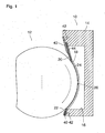
- an ink fountain 10 is set against a peripheral surface of an a gravured inking roller 12 of a proofer apparatus, so that ink may be applied to the surface of the inking roller.
- the ink fountain 10 has a body 14 defining an ink chamber 16 that extends in axial direction along the inking roller 12 and has an opening 18 that opens out towards the surface of the inking roller.
- the ink chamber 16 may be filled with liquid ink via a supply passage that has not been shown in the drawing.
- the opening 18 of the ink chamber 16 is bounded in circumferential direction of the inking roller 12 by an upstream doctor blade 20 and a downstream doctor blade 22.
- upstream and downstream refer to the direction of a rotation of the inking roller 12 that is indicated by an arrow in Fig. 1 .
- the opening 18 is bounded by arcuate seals 24 that engage the peripheral surface of the inking roller and interconnect the two doctor blades 20, 22.
- the seals 24 In the cross-sectional view in Fig. 1 , only one of the seals 24 is visible.
- the doctor blades 20, 22 and the seals 24 are formed by a one-piece sheet 26, e.g. a thin sheet of spring steel which may have a thickness in the order of magnitude of 0.15 mm.
- the doctor blade 20 forms an edge 28 that delimits the opening 18, and it is angled from the seals 24 along a straight line 30 that coincides with the edge 28.
- the downstream doctor blade 22 has an edge 32 and is angled from the seals 24 along a straight line 34 that coincides with the edge 32.
- the angle formed between the doctor blade 20 and the peripheral surface of the inking roller 12 is approximately 23°.
- the edge 28 wipes over the surface of the inking roller, so that the doctor blade 20 retains the ink in the ink chamber 16.
- the edge 32 of the downstream doctor blade 22 forms an angle of approximately 39° with the surface of the inking roller 12.
- the doctor blade 22 projects towards the surface of the inking roller 12 in the direction opposite to the direction of movement of that surface, so that the edge 32 scrapes over the surface of the inking roller.
- the inking roller has a pattern of minute pits which are filled with ink when the surface of the inking roller passes through the ink chamber 16. Then, when the surface passes the edge 32, the ink is scraped off from the surface of the inking roller, so that ink remains only in the pits thereof.
- the configuration of the doctor blades 20, 22 and the seals 24 shown in Fig. 2 may be obtained by cutting or punching the rectangular opening 18 out of a flat blank for the sheet 26 and pressing the sheet into the shape shown in Fig. 2 .
- the sheet 26 takes the configuration of a rectangular frame with the doctor blades 20 and 22 as longer (longitudinal) legs and the seals 24 as shorter legs.
- the process of punching and pressing may be performed in a single operation.
- the opening 18 may be cut out while the sheet is still in a flat shape, and the sheet is pressed into the desired shape in a subsequent separate step.
- This may have the result that the edge 32 engages the surface of the inking roller with an acute knife edge 36 as is shown in Fig. 3 .
- This effect may be enhanced by forming minute incisions 38 ( Fig. 2 ) at both ends of the edge 32.
- the depth of the incisions 38 has been exaggerated in Fig. 2 for illustration purposes. In practice, the depth of these incisions will be smaller than the thickness of the sheet metal forming the sheet 26.
- the acute knife edge 36 may also be formed by post-processing the edge 32, e.g. by sharpening the same in a grinding or hammering process.
- the sheet 26 is secured to the body 14 of the ink fountain by means of clamping plates 40 and bolts 42.
- a resilient cushion layer 44 is interposed between the sheet 26 and the body 14 of the ink fountain.
- the cushion layer 44 is congruent with the sheet 26 and consequently has a rectangular opening corresponding to the opening 18.
- the cushion layer 44 serves a seal between the sheet 26 and the body 14 of the ink fountain and also permits to resiliently bias the edges of the doctor blades 20, 22 as well as the seals 24 against the surface of the inking roller 12, thus assuring a good line contact between the doctor blades and the inking roller and a good surface contact between the seals 24 and the inking roller.
Landscapes
- Engineering & Computer Science (AREA)
- Mechanical Engineering (AREA)
- Inking, Control Or Cleaning Of Printing Machines (AREA)
Description
- The invention relates to an ink fountain for inking a roller, the fountain comprising an ink chamber extending along the roller and having an opening that opens out towards a peripheral surface of the roller, said opening being bounded by doctor blades in circumferential direction of the roller and by seals in axial direction of the roller.
- In the printing industry, ink fountains are used for inking a roller in a rotary printing press or in a so-called proofer apparatus that is used for making a colour proof prior to actual printing. For example, the roller to be inked may be a gravured inking roller or an anilox roller.
- A conventional ink fountain has a body that forms the ink chamber, and two separate blade members made of metal are clamped to the body so as to form the doctor blades. Separate seal members are mounted on both axial ends of the body.
- It is a drawback of this known construction that there is a risk of ink leaking out at joints formed between the doctor blades and the seal members, especially when, after a certain period of use, the doctor blades and the seals have been subject to differential wear. In order to prevent the leakage of ink, complicated and expensive mounting structures for the doctor blades and expensive seal designs are required.
- It is an object of the invention to provide a low-cost ink fountain that can reliably prevent ink from leaking out.
- According to the invention, in order to achieve this object, the seals and at least one of the doctor blades are formed by a one-piece sheet that is angled at an edge of the doctor blade.
- As the seals and the doctor blade are formed in one piece, there is no joint between them, and consequently there is no risk of ink leaking out. Moreover, problems with differential wear of the doctor blade and the seals are mitigated because the seals and the doctor blade are made of the same material, e.g. metal.
- More specific optional features of the invention are indicated in the dependent claims.
- In a preferred embodiment, the one-piece sheet forms two doctor blades that are connected by the seals. For example, the doctor blade and seal structure may be formed by cutting or punching a rectangular opening into a blank of sheet metal so as to obtain a sheet metal frame the longitudinal legs of which will form the doctor blades whereas the shorter legs will form the seals.
- At least one of the doctor blades may have a sharpened edge for engaging the roller.
- In order to provide a perfect seal between the sheet and the body forming the ink chamber, and in order to be able to evenly bias the doctor blades and the seals against the surface of the roller, a resilient cushion may be provided between the sheet and the body of the ink fountain.
- The ink fountain according to the invention is particularly suited for use in a proofer apparatus, e.g. a proofer apparatus of the type described in applicant's co-pending European patent application
EP 11 155 963.9 filed on February 25, 2011 - Document
EP-A-0374710 discloses an ink fountain according to the preamble of claim 1. - A preferred embodiment of the invention will now be described in conjunction with the drawings, wherein:
- Fig. 1
- is a schematic cross-sectional view of an ink fountain according to an embodiment of the invention;
- Fig. 2
- is a perspective view of a sheet forming doctor blades and seals of the ink fountain; and
- Fig. 3
- is an enlarged cross-sectional view of an edge of a doctor blade and an adjoining seal portion.
- As is shown in
Fig. 1 , anink fountain 10 is set against a peripheral surface of an agravured inking roller 12 of a proofer apparatus, so that ink may be applied to the surface of the inking roller. Theink fountain 10 has abody 14 defining anink chamber 16 that extends in axial direction along the inkingroller 12 and has anopening 18 that opens out towards the surface of the inking roller. Theink chamber 16 may be filled with liquid ink via a supply passage that has not been shown in the drawing. - The opening 18 of the
ink chamber 16 is bounded in circumferential direction of theinking roller 12 by anupstream doctor blade 20 and adownstream doctor blade 22. The terms "upstream" and "downstream" refer to the direction of a rotation of theinking roller 12 that is indicated by an arrow inFig. 1 . - In axial direction of the
inking roller 12, theopening 18 is bounded byarcuate seals 24 that engage the peripheral surface of the inking roller and interconnect the twodoctor blades Fig. 1 , only one of theseals 24 is visible. - As is shown in
Fig. 2 , thedoctor blades seals 24 are formed by a one-piece sheet 26, e.g. a thin sheet of spring steel which may have a thickness in the order of magnitude of 0.15 mm. - The
doctor blade 20 forms anedge 28 that delimits theopening 18, and it is angled from theseals 24 along astraight line 30 that coincides with theedge 28. Similarly, thedownstream doctor blade 22 has anedge 32 and is angled from theseals 24 along astraight line 34 that coincides with theedge 32. - In the mounted position shown in
Fig. 1 , the angle formed between thedoctor blade 20 and the peripheral surface of the inking roller 12 (or, more precisely, the tangent thereto) is approximately 23°. When the inkingroller 12 rotates in the direction of the arrow inFig. 1 , theedge 28 wipes over the surface of the inking roller, so that thedoctor blade 20 retains the ink in theink chamber 16. - The
edge 32 of thedownstream doctor blade 22 forms an angle of approximately 39° with the surface of the inkingroller 12. The doctor blade 22 projects towards the surface of the inkingroller 12 in the direction opposite to the direction of movement of that surface, so that theedge 32 scrapes over the surface of the inking roller. Typically, the inking roller has a pattern of minute pits which are filled with ink when the surface of the inking roller passes through theink chamber 16. Then, when the surface passes theedge 32, the ink is scraped off from the surface of the inking roller, so that ink remains only in the pits thereof. - The configuration of the
doctor blades seals 24 shown inFig. 2 may be obtained by cutting or punching therectangular opening 18 out of a flat blank for thesheet 26 and pressing the sheet into the shape shown inFig. 2 . As a result, thesheet 26 takes the configuration of a rectangular frame with thedoctor blades seals 24 as shorter legs. - The process of punching and pressing may be performed in a single operation. Alternatively, the
opening 18 may be cut out while the sheet is still in a flat shape, and the sheet is pressed into the desired shape in a subsequent separate step. This may have the result that theedge 32 engages the surface of the inking roller with anacute knife edge 36 as is shown inFig. 3 . This effect may be enhanced by forming minute incisions 38 (Fig. 2 ) at both ends of theedge 32. It should be noted that the depth of theincisions 38 has been exaggerated inFig. 2 for illustration purposes. In practice, the depth of these incisions will be smaller than the thickness of the sheet metal forming thesheet 26. - As an alternative, the
acute knife edge 36 may also be formed by post-processing theedge 32, e.g. by sharpening the same in a grinding or hammering process. - As is shown in
Fig. 1 , thesheet 26 is secured to thebody 14 of the ink fountain by means ofclamping plates 40 andbolts 42. Aresilient cushion layer 44 is interposed between thesheet 26 and thebody 14 of the ink fountain. Thecushion layer 44 is congruent with thesheet 26 and consequently has a rectangular opening corresponding to theopening 18. When thebolts 42 are tightened, theclamping plates 40 press thedoctor blades body 14 and slightly compress thecushion layer 44. Thecushion layer 44 serves a seal between thesheet 26 and thebody 14 of the ink fountain and also permits to resiliently bias the edges of thedoctor blades seals 24 against the surface of theinking roller 12, thus assuring a good line contact between the doctor blades and the inking roller and a good surface contact between theseals 24 and the inking roller.
Claims (6)
- An ink fountain for inking a roller (12), the fountain (10) comprising an ink chamber (16) extending along the roller (12) and having an opening (18) that opens out towards a peripheral surface of the roller (12), said opening (18) being bounded by doctor blades (20, 22) in circumferential direction of the roller (12) and by seals (24) in axial direction of the roller, characterized in that the seals (24) and at least one of the doctor blades (20, 22) are formed by a one-piece sheet (26) that is angled at an edge (28, 32) of the doctor blade (20, 22).
- The ink fountain according to claim 1, wherein the sheet (26) is made of metal.
- The ink fountain according to claim 1 or 2, wherein the sheet (26) forms two parallel doctor blades (20, 22) that are interconnected at both ends by the seals (24).
- The ink fountain according to any of the preceding claims, wherein the edge (32) of at least one of the doctor blades (20, 22) is configured to engage the surface of the roller (12) with a sharpened knife edge (36).
- The ink fountain according to any of the preceding claims, wherein an elastic cushion layer (44) is interposed between the sheet (26) and a body (14) of the ink fountain (10).
- A proofer apparatus comprising an ink-accepting roller (12), characterized by an ink fountain (10) according to any of the preceding claims for inking the roller (12).
Priority Applications (2)
| Application Number | Priority Date | Filing Date | Title |
|---|---|---|---|
| EP20110192758 EP2602111B1 (en) | 2011-12-09 | 2011-12-09 | Ink Fountain |
| ES11192758.8T ES2496066T3 (en) | 2011-12-09 | 2011-12-09 | Ink fountain |
Applications Claiming Priority (1)
| Application Number | Priority Date | Filing Date | Title |
|---|---|---|---|
| EP20110192758 EP2602111B1 (en) | 2011-12-09 | 2011-12-09 | Ink Fountain |
Publications (2)
| Publication Number | Publication Date |
|---|---|
| EP2602111A1 EP2602111A1 (en) | 2013-06-12 |
| EP2602111B1 true EP2602111B1 (en) | 2014-07-02 |
Family
ID=45346311
Family Applications (1)
| Application Number | Title | Priority Date | Filing Date |
|---|---|---|---|
| EP20110192758 Active EP2602111B1 (en) | 2011-12-09 | 2011-12-09 | Ink Fountain |
Country Status (2)
| Country | Link |
|---|---|
| EP (1) | EP2602111B1 (en) |
| ES (1) | ES2496066T3 (en) |
Families Citing this family (2)
| Publication number | Priority date | Publication date | Assignee | Title |
|---|---|---|---|---|
| JP6183765B1 (en) * | 2017-03-06 | 2017-08-23 | 下村 恭一 | Ink scattering prevention cover and gravure printing device |
| EP3693167A1 (en) | 2019-02-11 | 2020-08-12 | Bobst Bielefeld GmbH | Printing system with ink reservoir |
Family Cites Families (2)
| Publication number | Priority date | Publication date | Assignee | Title |
|---|---|---|---|---|
| US2595070A (en) * | 1948-03-02 | 1952-04-29 | Rca Corp | Ink transfer device |
| DE3843017C1 (en) * | 1988-12-21 | 1990-05-23 | Man Roland Druckmaschinen Ag, 6050 Offenbach, De |
-
2011
- 2011-12-09 ES ES11192758.8T patent/ES2496066T3/en active Active
- 2011-12-09 EP EP20110192758 patent/EP2602111B1/en active Active
Also Published As
| Publication number | Publication date |
|---|---|
| ES2496066T3 (en) | 2014-09-18 |
| EP2602111A1 (en) | 2013-06-12 |
Similar Documents
| Publication | Publication Date | Title |
|---|---|---|
| DE102017211843B4 (en) | Printing machine with a printing unit operating according to the inkjet method and method for preparing printing material | |
| CA2005454C (en) | Chambered doctor blade inker system | |
| JPH0329592B2 (en) | ||
| EP2602111A1 (en) | Ink Fountain | |
| EP0812687A3 (en) | Ink unit for printing press and method | |
| CN201685513U (en) | Non-stop scraping blade replacement device | |
| JP7109668B2 (en) | Doctor blade, doctor blade chamber and printing unit equipped with these | |
| CN105813847A (en) | Device and method for operating ink feed mechanism comprising an ink blade, and mounting device and method for updating ink blade | |
| US2404689A (en) | Doctor blade | |
| EP0722833B1 (en) | Inking rail device | |
| EP1412186B1 (en) | Printing press scraping blade | |
| DE102007041756B4 (en) | ink chamber | |
| JPH09164661A (en) | Are division type ink fountain adjusting plate for rotary press | |
| JP3667003B2 (en) | Doctor holder | |
| DE8908243U1 (en) | Offset printing unit | |
| CN201979788U (en) | Printing ink scraping knife with titanium nitride metal coating | |
| JP4528931B2 (en) | Chamber type ink supply device | |
| WO2008117568A1 (en) | Operating method of rotary printing machine and rotary printing machine | |
| EP2821228A1 (en) | Seal for squeegee devices | |
| DE102013213060B4 (en) | Device and method for guiding sheets in a printing unit that is not involved in the printing process | |
| CN209063680U (en) | A kind of base gravure ink doctor blade holder | |
| CN2936734Y (en) | Indirect printing integlio printer | |
| CA1062956A (en) | Pressurized ink applicator for intaglio printing press | |
| DE3225982A1 (en) | INK FOR A LITHOGRAPHIC PRINTING MACHINE | |
| US6286426B1 (en) | Doctor blades |
Legal Events
| Date | Code | Title | Description |
|---|---|---|---|
| PUAI | Public reference made under article 153(3) epc to a published international application that has entered the european phase |
Free format text: ORIGINAL CODE: 0009012 |
|
| AK | Designated contracting states |
Kind code of ref document: A1 Designated state(s): AL AT BE BG CH CY CZ DE DK EE ES FI FR GB GR HR HU IE IS IT LI LT LU LV MC MK MT NL NO PL PT RO RS SE SI SK SM TR |
|
| AX | Request for extension of the european patent |
Extension state: BA ME |
|
| 17P | Request for examination filed |
Effective date: 20131204 |
|
| RBV | Designated contracting states (corrected) |
Designated state(s): AL AT BE BG CH CY CZ DE DK EE ES FI FR GB GR HR HU IE IS IT LI LT LU LV MC MK MT NL NO PL PT RO RS SE SI SK SM TR |
|
| GRAP | Despatch of communication of intention to grant a patent |
Free format text: ORIGINAL CODE: EPIDOSNIGR1 |
|
| RIC1 | Information provided on ipc code assigned before grant |
Ipc: B41F 31/07 20060101ALI20140107BHEP Ipc: B41F 9/10 20060101ALI20140107BHEP Ipc: B41F 31/06 20060101ALI20140107BHEP Ipc: B41F 9/06 20060101AFI20140107BHEP |
|
| INTG | Intention to grant announced |
Effective date: 20140122 |
|
| GRAS | Grant fee paid |
Free format text: ORIGINAL CODE: EPIDOSNIGR3 |
|
| GRAA | (expected) grant |
Free format text: ORIGINAL CODE: 0009210 |
|
| AK | Designated contracting states |
Kind code of ref document: B1 Designated state(s): AL AT BE BG CH CY CZ DE DK EE ES FI FR GB GR HR HU IE IS IT LI LT LU LV MC MK MT NL NO PL PT RO RS SE SI SK SM TR |
|
| REG | Reference to a national code |
Ref country code: GB Ref legal event code: FG4D |
|
| REG | Reference to a national code |
Ref country code: CH Ref legal event code: EP Ref country code: AT Ref legal event code: REF Ref document number: 675693 Country of ref document: AT Kind code of ref document: T Effective date: 20140715 |
|
| REG | Reference to a national code |
Ref country code: IE Ref legal event code: FG4D |
|
| REG | Reference to a national code |
Ref country code: DE Ref legal event code: R096 Ref document number: 602011008088 Country of ref document: DE Effective date: 20140814 |
|
| REG | Reference to a national code |
Ref country code: ES Ref legal event code: FG2A Ref document number: 2496066 Country of ref document: ES Kind code of ref document: T3 Effective date: 20140918 |
|
| REG | Reference to a national code |
Ref country code: AT Ref legal event code: MK05 Ref document number: 675693 Country of ref document: AT Kind code of ref document: T Effective date: 20140702 |
|
| REG | Reference to a national code |
Ref country code: NL Ref legal event code: VDEP Effective date: 20140702 |
|
| REG | Reference to a national code |
Ref country code: LT Ref legal event code: MG4D |
|
| PG25 | Lapsed in a contracting state [announced via postgrant information from national office to epo] |
Ref country code: CZ Free format text: LAPSE BECAUSE OF FAILURE TO SUBMIT A TRANSLATION OF THE DESCRIPTION OR TO PAY THE FEE WITHIN THE PRESCRIBED TIME-LIMIT Effective date: 20140702 Ref country code: SE Free format text: LAPSE BECAUSE OF FAILURE TO SUBMIT A TRANSLATION OF THE DESCRIPTION OR TO PAY THE FEE WITHIN THE PRESCRIBED TIME-LIMIT Effective date: 20140702 Ref country code: NO Free format text: LAPSE BECAUSE OF FAILURE TO SUBMIT A TRANSLATION OF THE DESCRIPTION OR TO PAY THE FEE WITHIN THE PRESCRIBED TIME-LIMIT Effective date: 20141002 Ref country code: PT Free format text: LAPSE BECAUSE OF FAILURE TO SUBMIT A TRANSLATION OF THE DESCRIPTION OR TO PAY THE FEE WITHIN THE PRESCRIBED TIME-LIMIT Effective date: 20141103 Ref country code: GR Free format text: LAPSE BECAUSE OF FAILURE TO SUBMIT A TRANSLATION OF THE DESCRIPTION OR TO PAY THE FEE WITHIN THE PRESCRIBED TIME-LIMIT Effective date: 20141003 Ref country code: BG Free format text: LAPSE BECAUSE OF FAILURE TO SUBMIT A TRANSLATION OF THE DESCRIPTION OR TO PAY THE FEE WITHIN THE PRESCRIBED TIME-LIMIT Effective date: 20141002 Ref country code: LT Free format text: LAPSE BECAUSE OF FAILURE TO SUBMIT A TRANSLATION OF THE DESCRIPTION OR TO PAY THE FEE WITHIN THE PRESCRIBED TIME-LIMIT Effective date: 20140702 Ref country code: FI Free format text: LAPSE BECAUSE OF FAILURE TO SUBMIT A TRANSLATION OF THE DESCRIPTION OR TO PAY THE FEE WITHIN THE PRESCRIBED TIME-LIMIT Effective date: 20140702 |
|
| PG25 | Lapsed in a contracting state [announced via postgrant information from national office to epo] |
Ref country code: CY Free format text: LAPSE BECAUSE OF FAILURE TO SUBMIT A TRANSLATION OF THE DESCRIPTION OR TO PAY THE FEE WITHIN THE PRESCRIBED TIME-LIMIT Effective date: 20140702 Ref country code: PL Free format text: LAPSE BECAUSE OF FAILURE TO SUBMIT A TRANSLATION OF THE DESCRIPTION OR TO PAY THE FEE WITHIN THE PRESCRIBED TIME-LIMIT Effective date: 20140702 Ref country code: HR Free format text: LAPSE BECAUSE OF FAILURE TO SUBMIT A TRANSLATION OF THE DESCRIPTION OR TO PAY THE FEE WITHIN THE PRESCRIBED TIME-LIMIT Effective date: 20140702 Ref country code: NL Free format text: LAPSE BECAUSE OF FAILURE TO SUBMIT A TRANSLATION OF THE DESCRIPTION OR TO PAY THE FEE WITHIN THE PRESCRIBED TIME-LIMIT Effective date: 20140702 Ref country code: RS Free format text: LAPSE BECAUSE OF FAILURE TO SUBMIT A TRANSLATION OF THE DESCRIPTION OR TO PAY THE FEE WITHIN THE PRESCRIBED TIME-LIMIT Effective date: 20140702 Ref country code: LV Free format text: LAPSE BECAUSE OF FAILURE TO SUBMIT A TRANSLATION OF THE DESCRIPTION OR TO PAY THE FEE WITHIN THE PRESCRIBED TIME-LIMIT Effective date: 20140702 Ref country code: IS Free format text: LAPSE BECAUSE OF FAILURE TO SUBMIT A TRANSLATION OF THE DESCRIPTION OR TO PAY THE FEE WITHIN THE PRESCRIBED TIME-LIMIT Effective date: 20141102 Ref country code: AT Free format text: LAPSE BECAUSE OF FAILURE TO SUBMIT A TRANSLATION OF THE DESCRIPTION OR TO PAY THE FEE WITHIN THE PRESCRIBED TIME-LIMIT Effective date: 20140702 |
|
| REG | Reference to a national code |
Ref country code: DE Ref legal event code: R097 Ref document number: 602011008088 Country of ref document: DE |
|
| PG25 | Lapsed in a contracting state [announced via postgrant information from national office to epo] |
Ref country code: DK Free format text: LAPSE BECAUSE OF FAILURE TO SUBMIT A TRANSLATION OF THE DESCRIPTION OR TO PAY THE FEE WITHIN THE PRESCRIBED TIME-LIMIT Effective date: 20140702 Ref country code: EE Free format text: LAPSE BECAUSE OF FAILURE TO SUBMIT A TRANSLATION OF THE DESCRIPTION OR TO PAY THE FEE WITHIN THE PRESCRIBED TIME-LIMIT Effective date: 20140702 Ref country code: RO Free format text: LAPSE BECAUSE OF FAILURE TO SUBMIT A TRANSLATION OF THE DESCRIPTION OR TO PAY THE FEE WITHIN THE PRESCRIBED TIME-LIMIT Effective date: 20140702 Ref country code: SK Free format text: LAPSE BECAUSE OF FAILURE TO SUBMIT A TRANSLATION OF THE DESCRIPTION OR TO PAY THE FEE WITHIN THE PRESCRIBED TIME-LIMIT Effective date: 20140702 |
|
| PLBE | No opposition filed within time limit |
Free format text: ORIGINAL CODE: 0009261 |
|
| STAA | Information on the status of an ep patent application or granted ep patent |
Free format text: STATUS: NO OPPOSITION FILED WITHIN TIME LIMIT |
|
| 26N | No opposition filed |
Effective date: 20150407 |
|
| PG25 | Lapsed in a contracting state [announced via postgrant information from national office to epo] |
Ref country code: BE Free format text: LAPSE BECAUSE OF NON-PAYMENT OF DUE FEES Effective date: 20141231 |
|
| PG25 | Lapsed in a contracting state [announced via postgrant information from national office to epo] |
Ref country code: LU Free format text: LAPSE BECAUSE OF FAILURE TO SUBMIT A TRANSLATION OF THE DESCRIPTION OR TO PAY THE FEE WITHIN THE PRESCRIBED TIME-LIMIT Effective date: 20141209 |
|
| REG | Reference to a national code |
Ref country code: CH Ref legal event code: PL |
|
| REG | Reference to a national code |
Ref country code: IE Ref legal event code: MM4A |
|
| REG | Reference to a national code |
Ref country code: FR Ref legal event code: ST Effective date: 20150831 |
|
| PG25 | Lapsed in a contracting state [announced via postgrant information from national office to epo] |
Ref country code: LI Free format text: LAPSE BECAUSE OF NON-PAYMENT OF DUE FEES Effective date: 20141231 Ref country code: CH Free format text: LAPSE BECAUSE OF NON-PAYMENT OF DUE FEES Effective date: 20141231 Ref country code: IE Free format text: LAPSE BECAUSE OF NON-PAYMENT OF DUE FEES Effective date: 20141209 |
|
| PG25 | Lapsed in a contracting state [announced via postgrant information from national office to epo] |
Ref country code: FR Free format text: LAPSE BECAUSE OF NON-PAYMENT OF DUE FEES Effective date: 20141231 Ref country code: SI Free format text: LAPSE BECAUSE OF FAILURE TO SUBMIT A TRANSLATION OF THE DESCRIPTION OR TO PAY THE FEE WITHIN THE PRESCRIBED TIME-LIMIT Effective date: 20140702 |
|
| PG25 | Lapsed in a contracting state [announced via postgrant information from national office to epo] |
Ref country code: SM Free format text: LAPSE BECAUSE OF FAILURE TO SUBMIT A TRANSLATION OF THE DESCRIPTION OR TO PAY THE FEE WITHIN THE PRESCRIBED TIME-LIMIT Effective date: 20140702 |
|
| PG25 | Lapsed in a contracting state [announced via postgrant information from national office to epo] |
Ref country code: MC Free format text: LAPSE BECAUSE OF FAILURE TO SUBMIT A TRANSLATION OF THE DESCRIPTION OR TO PAY THE FEE WITHIN THE PRESCRIBED TIME-LIMIT Effective date: 20140702 |
|
| PG25 | Lapsed in a contracting state [announced via postgrant information from national office to epo] |
Ref country code: HU Free format text: LAPSE BECAUSE OF FAILURE TO SUBMIT A TRANSLATION OF THE DESCRIPTION OR TO PAY THE FEE WITHIN THE PRESCRIBED TIME-LIMIT; INVALID AB INITIO Effective date: 20111209 Ref country code: MT Free format text: LAPSE BECAUSE OF FAILURE TO SUBMIT A TRANSLATION OF THE DESCRIPTION OR TO PAY THE FEE WITHIN THE PRESCRIBED TIME-LIMIT Effective date: 20140702 Ref country code: TR Free format text: LAPSE BECAUSE OF FAILURE TO SUBMIT A TRANSLATION OF THE DESCRIPTION OR TO PAY THE FEE WITHIN THE PRESCRIBED TIME-LIMIT Effective date: 20140702 Ref country code: BE Free format text: LAPSE BECAUSE OF FAILURE TO SUBMIT A TRANSLATION OF THE DESCRIPTION OR TO PAY THE FEE WITHIN THE PRESCRIBED TIME-LIMIT Effective date: 20140702 |
|
| GBPC | Gb: european patent ceased through non-payment of renewal fee |
Effective date: 20151209 |
|
| PG25 | Lapsed in a contracting state [announced via postgrant information from national office to epo] |
Ref country code: GB Free format text: LAPSE BECAUSE OF NON-PAYMENT OF DUE FEES Effective date: 20151209 |
|
| REG | Reference to a national code |
Ref country code: DE Ref legal event code: R082 Ref document number: 602011008088 Country of ref document: DE |
|
| PG25 | Lapsed in a contracting state [announced via postgrant information from national office to epo] |
Ref country code: MK Free format text: LAPSE BECAUSE OF FAILURE TO SUBMIT A TRANSLATION OF THE DESCRIPTION OR TO PAY THE FEE WITHIN THE PRESCRIBED TIME-LIMIT Effective date: 20140702 |
|
| PG25 | Lapsed in a contracting state [announced via postgrant information from national office to epo] |
Ref country code: AL Free format text: LAPSE BECAUSE OF FAILURE TO SUBMIT A TRANSLATION OF THE DESCRIPTION OR TO PAY THE FEE WITHIN THE PRESCRIBED TIME-LIMIT Effective date: 20140702 |
|
| P01 | Opt-out of the competence of the unified patent court (upc) registered |
Effective date: 20230519 |
|
| PGFP | Annual fee paid to national office [announced via postgrant information from national office to epo] |
Ref country code: DE Payment date: 20251211 Year of fee payment: 15 |
|
| PGFP | Annual fee paid to national office [announced via postgrant information from national office to epo] |
Ref country code: IT Payment date: 20251223 Year of fee payment: 15 |
|
| PGFP | Annual fee paid to national office [announced via postgrant information from national office to epo] |
Ref country code: ES Payment date: 20260130 Year of fee payment: 15 |