EP2602082A2 - Apparatus and method for forming a hollow component - Google Patents
Apparatus and method for forming a hollow component Download PDFInfo
- Publication number
- EP2602082A2 EP2602082A2 EP12190343.9A EP12190343A EP2602082A2 EP 2602082 A2 EP2602082 A2 EP 2602082A2 EP 12190343 A EP12190343 A EP 12190343A EP 2602082 A2 EP2602082 A2 EP 2602082A2
- Authority
- EP
- European Patent Office
- Prior art keywords
- mandrel
- flexible elements
- axis
- flexible
- flanges
- Prior art date
- Legal status (The legal status is an assumption and is not a legal conclusion. Google has not performed a legal analysis and makes no representation as to the accuracy of the status listed.)
- Granted
Links
- 238000000034 method Methods 0.000 title claims abstract description 23
- 239000002131 composite material Substances 0.000 claims abstract description 22
- 239000000835 fiber Substances 0.000 claims abstract description 19
- 239000000463 material Substances 0.000 claims description 30
- 230000008602 contraction Effects 0.000 claims description 7
- -1 polypropylene Polymers 0.000 claims description 7
- OKTJSMMVPCPJKN-UHFFFAOYSA-N Carbon Chemical compound [C] OKTJSMMVPCPJKN-UHFFFAOYSA-N 0.000 claims description 4
- 239000004743 Polypropylene Substances 0.000 claims description 4
- 229910052786 argon Inorganic materials 0.000 claims description 4
- 229910052799 carbon Inorganic materials 0.000 claims description 4
- 229910052734 helium Inorganic materials 0.000 claims description 4
- 239000002648 laminated material Substances 0.000 claims description 4
- 229910052757 nitrogen Inorganic materials 0.000 claims description 4
- 229920001155 polypropylene Polymers 0.000 claims description 4
- 239000004810 polytetrafluoroethylene Substances 0.000 claims description 4
- 229920001343 polytetrafluoroethylene Polymers 0.000 claims description 4
- 239000004800 polyvinyl chloride Substances 0.000 claims description 4
- 229920000915 polyvinyl chloride Polymers 0.000 claims description 4
- 230000001154 acute effect Effects 0.000 claims description 3
- 239000002033 PVDF binder Substances 0.000 claims description 2
- 239000004952 Polyamide Substances 0.000 claims description 2
- 239000004698 Polyethylene Substances 0.000 claims description 2
- 229910000831 Steel Inorganic materials 0.000 claims description 2
- 239000004760 aramid Substances 0.000 claims description 2
- 229920003235 aromatic polyamide Polymers 0.000 claims description 2
- 239000003365 glass fiber Substances 0.000 claims description 2
- 229920002647 polyamide Polymers 0.000 claims description 2
- 229920000573 polyethylene Polymers 0.000 claims description 2
- 229920002981 polyvinylidene fluoride Polymers 0.000 claims description 2
- 239000010703 silicon Substances 0.000 claims description 2
- 229910052710 silicon Inorganic materials 0.000 claims description 2
- 229910001220 stainless steel Inorganic materials 0.000 claims description 2
- 239000010935 stainless steel Substances 0.000 claims description 2
- 239000010959 steel Substances 0.000 claims description 2
- 229920000785 ultra high molecular weight polyethylene Polymers 0.000 claims description 2
- 239000007789 gas Substances 0.000 description 6
- 238000004519 manufacturing process Methods 0.000 description 6
- 229920005989 resin Polymers 0.000 description 4
- 239000011347 resin Substances 0.000 description 4
- 230000002411 adverse Effects 0.000 description 3
- 238000009730 filament winding Methods 0.000 description 3
- XKRFYHLGVUSROY-UHFFFAOYSA-N Argon Chemical compound [Ar] XKRFYHLGVUSROY-UHFFFAOYSA-N 0.000 description 2
- IJGRMHOSHXDMSA-UHFFFAOYSA-N Atomic nitrogen Chemical compound N#N IJGRMHOSHXDMSA-UHFFFAOYSA-N 0.000 description 2
- 239000011248 coating agent Substances 0.000 description 2
- 238000000576 coating method Methods 0.000 description 2
- 239000011261 inert gas Substances 0.000 description 2
- 239000002184 metal Substances 0.000 description 2
- 239000004677 Nylon Substances 0.000 description 1
- 230000015572 biosynthetic process Effects 0.000 description 1
- 238000007796 conventional method Methods 0.000 description 1
- 238000005260 corrosion Methods 0.000 description 1
- 230000007797 corrosion Effects 0.000 description 1
- 238000013036 cure process Methods 0.000 description 1
- 238000005490 dry winding Methods 0.000 description 1
- 230000000694 effects Effects 0.000 description 1
- 230000002708 enhancing effect Effects 0.000 description 1
- 239000003822 epoxy resin Substances 0.000 description 1
- 238000010438 heat treatment Methods 0.000 description 1
- 239000001307 helium Substances 0.000 description 1
- SWQJXJOGLNCZEY-UHFFFAOYSA-N helium atom Chemical compound [He] SWQJXJOGLNCZEY-UHFFFAOYSA-N 0.000 description 1
- 229920000647 polyepoxide Polymers 0.000 description 1
- 229920001187 thermosetting polymer Polymers 0.000 description 1
- 238000004046 wet winding Methods 0.000 description 1
- 238000004804 winding Methods 0.000 description 1
Images

Classifications
-
- B—PERFORMING OPERATIONS; TRANSPORTING
- B29—WORKING OF PLASTICS; WORKING OF SUBSTANCES IN A PLASTIC STATE IN GENERAL
- B29C—SHAPING OR JOINING OF PLASTICS; SHAPING OF MATERIAL IN A PLASTIC STATE, NOT OTHERWISE PROVIDED FOR; AFTER-TREATMENT OF THE SHAPED PRODUCTS, e.g. REPAIRING
- B29C70/00—Shaping composites, i.e. plastics material comprising reinforcements, fillers or preformed parts, e.g. inserts
- B29C70/04—Shaping composites, i.e. plastics material comprising reinforcements, fillers or preformed parts, e.g. inserts comprising reinforcements only, e.g. self-reinforcing plastics
- B29C70/28—Shaping operations therefor
- B29C70/30—Shaping by lay-up, i.e. applying fibres, tape or broadsheet on a mould, former or core; Shaping by spray-up, i.e. spraying of fibres on a mould, former or core
- B29C70/32—Shaping by lay-up, i.e. applying fibres, tape or broadsheet on a mould, former or core; Shaping by spray-up, i.e. spraying of fibres on a mould, former or core on a rotating mould, former or core
-
- B—PERFORMING OPERATIONS; TRANSPORTING
- B29—WORKING OF PLASTICS; WORKING OF SUBSTANCES IN A PLASTIC STATE IN GENERAL
- B29C—SHAPING OR JOINING OF PLASTICS; SHAPING OF MATERIAL IN A PLASTIC STATE, NOT OTHERWISE PROVIDED FOR; AFTER-TREATMENT OF THE SHAPED PRODUCTS, e.g. REPAIRING
- B29C33/00—Moulds or cores; Details thereof or accessories therefor
- B29C33/30—Mounting, exchanging or centering
- B29C33/308—Adjustable moulds
-
- B—PERFORMING OPERATIONS; TRANSPORTING
- B29—WORKING OF PLASTICS; WORKING OF SUBSTANCES IN A PLASTIC STATE IN GENERAL
- B29C—SHAPING OR JOINING OF PLASTICS; SHAPING OF MATERIAL IN A PLASTIC STATE, NOT OTHERWISE PROVIDED FOR; AFTER-TREATMENT OF THE SHAPED PRODUCTS, e.g. REPAIRING
- B29C33/00—Moulds or cores; Details thereof or accessories therefor
- B29C33/44—Moulds or cores; Details thereof or accessories therefor with means for, or specially constructed to facilitate, the removal of articles, e.g. of undercut articles
- B29C33/48—Moulds or cores; Details thereof or accessories therefor with means for, or specially constructed to facilitate, the removal of articles, e.g. of undercut articles with means for collapsing or disassembling
- B29C33/50—Moulds or cores; Details thereof or accessories therefor with means for, or specially constructed to facilitate, the removal of articles, e.g. of undercut articles with means for collapsing or disassembling elastic or flexible
- B29C33/505—Moulds or cores; Details thereof or accessories therefor with means for, or specially constructed to facilitate, the removal of articles, e.g. of undercut articles with means for collapsing or disassembling elastic or flexible cores or mandrels, e.g. inflatable
-
- B—PERFORMING OPERATIONS; TRANSPORTING
- B29—WORKING OF PLASTICS; WORKING OF SUBSTANCES IN A PLASTIC STATE IN GENERAL
- B29C—SHAPING OR JOINING OF PLASTICS; SHAPING OF MATERIAL IN A PLASTIC STATE, NOT OTHERWISE PROVIDED FOR; AFTER-TREATMENT OF THE SHAPED PRODUCTS, e.g. REPAIRING
- B29C33/00—Moulds or cores; Details thereof or accessories therefor
- B29C33/30—Mounting, exchanging or centering
- B29C33/301—Modular mould systems [MMS], i.e. moulds built up by stacking mould elements, e.g. plates, blocks, rods
- B29C33/302—Assembling a large number of mould elements to constitute one cavity
-
- B—PERFORMING OPERATIONS; TRANSPORTING
- B29—WORKING OF PLASTICS; WORKING OF SUBSTANCES IN A PLASTIC STATE IN GENERAL
- B29L—INDEXING SCHEME ASSOCIATED WITH SUBCLASS B29C, RELATING TO PARTICULAR ARTICLES
- B29L2022/00—Hollow articles
-
- B—PERFORMING OPERATIONS; TRANSPORTING
- B29—WORKING OF PLASTICS; WORKING OF SUBSTANCES IN A PLASTIC STATE IN GENERAL
- B29L—INDEXING SCHEME ASSOCIATED WITH SUBCLASS B29C, RELATING TO PARTICULAR ARTICLES
- B29L2023/00—Tubular articles
- B29L2023/22—Tubes or pipes, i.e. rigid
-
- Y—GENERAL TAGGING OF NEW TECHNOLOGICAL DEVELOPMENTS; GENERAL TAGGING OF CROSS-SECTIONAL TECHNOLOGIES SPANNING OVER SEVERAL SECTIONS OF THE IPC; TECHNICAL SUBJECTS COVERED BY FORMER USPC CROSS-REFERENCE ART COLLECTIONS [XRACs] AND DIGESTS
- Y10—TECHNICAL SUBJECTS COVERED BY FORMER USPC
- Y10T—TECHNICAL SUBJECTS COVERED BY FORMER US CLASSIFICATION
- Y10T156/00—Adhesive bonding and miscellaneous chemical manufacture
- Y10T156/10—Methods of surface bonding and/or assembly therefor
- Y10T156/1002—Methods of surface bonding and/or assembly therefor with permanent bending or reshaping or surface deformation of self sustaining lamina
Definitions
- This invention relates to a method and apparatus for forming a hollow component and particularly, but not exclusively, to the forming of hollow, revolute components.
- Filament winding, fibre placement, and tape laying are three known methods for applying composite fibres to a rotating mandrel to form a hollow component.
- the mandrel In a filament winding process, the mandrel is typically suspended horizontally between end supports. The mandrel rotates about the horizontal axis as a fibre application instrument moves back and forth along the length of the mandrel, placing fibres onto the mandrel in a pre-determined configuration.
- the filament winding apparatus passes the fibre material through a resin bath just before the material touches the mandrel. This is called wet winding.
- wet winding In other applications, often termed dry winding, the fibre has been pre-impregnated with resin, eliminating the need for the resin bath. Following oven or autoclave curing of the resin, the mandrel can remain in place and become part of the wound component, or it can be removed.
- Fiber tape laying is similar to the fibre placement process described above except that fibre tape, rather than individual fibre tows, is laid down on the rotating mandrel to form the hollow component. Narrower tape widths provide enhanced steerability and control during application and are often used for the production of hollow components having a non-cylindrical shape.
- a problem with this type of component forming is that the geometry of the component is limited by the need to be able to remove the mandrel from the finished cured component.
- components having a double curved form, such as a convergent-divergent nozzle cannot be formed without the use of multi-piece mandrels. This can cause joint discontinuities which in turn can be difficult and costly to rectify.
- a further problem with conventional tooling is that a separate mandrel must be manufactured for each component form and size.
- Conventional mandrels are generally formed as ring roll forged metal components which make their production costly and time-consuming.
- the need for separate mandrels for each component form and size results in the need to store large quantities of mandrels which is inconvenient.
- a mandrel for forming a hollow component from a laminated material comprising first and second flanges spaced apart from one another along an axis of the mandrel, a plurality of flexible elements extending between the first and second flanges and a means for adjusting the position of each of the flexible elements along the length of the axis of the mandrel, such that the plurality of flexible elements define a three-dimensional revolute form.
- a mandrel having two flanges with a plurality of flexible elements extending therebetween and a means of adjusting the position of each of the flexible elements allows a single mandrel to be configured to take up a wide range of geometrical forms and sizes. This makes the mandrel of the invention flexible and cost effective. Furthermore, the adjusting means allows changes and adjustments to be made to the form of the mandrel during production, for example to cater for changing requirements or to correct errors.
- the present invention enables a wide variety of mandrel forms, i.e. variation in shapes and sizes, to be created using a single tooling set. This greatly reduces the quantity of separate mandrels required to produce a variety of different hollow components and greatly reduces tooling and manufacturing costs, particularly for prototype production.
- the two flanges are circular with the flexible elements being regularly spaced around the respective peripheries of the flanges.
- the flexible elements extend between the flanges and are each aligned parallel with the axis of rotation. In this arrangement, symmetrically reducing or increasing the radius of the flexible elements can produce a rotationally symmetrical hollow component.
- the flanges may be non-circular and/or the flexible elements may be unevenly spaced around the peripheries of the flanges. In this way, rotationally asymmetrical forms can be produced.
- the two flanges are parallel to one another and each flange is oriented normally to the axis of rotation of the mandrel. In alternative arrangements, one or both of the flanges may be oriented at different angles to the axis of rotation.
- the flexible elements may be formed as metal braided cords or wires.
- Each of the cords or wires passes through respective holes in each of the two flanges.
- the holes in the flanges may be provided with guide rollers to reduce frictional forces between the cords or wires and the flanges. Reducing the frictional forces between the cords or wires and the flanges may reduce any variation in tensional loads between the cords or wires.
- first and second flanges are separated from one another by a central post aligned with the axis of the mandrel.
- the two flanges are connected together and separated from one another by a central post, to form a spool.
- the central post is aligned with the axis of rotation of the mandrel.
- the means for adjusting the position of each of the flexible elements comprises at least one flexible element support frame, positionable axially along the axis of the mandrel and having a plurality of locating portions, each of the plurality of locating portions being connected to a respective one of the plurality of flexible elements.
- the support frame comprises a plurality of spokes, with each of the spokes being provided, at its radially outermost end, with a locating portion in the form of an end block which is secured to the flexible element.
- the axial position of the support frame along the axis of the mandrel and the radial position of the locating portions are adjustable. This arrangement enables the position of the flexible elements, both radially and circumferentially, to be varied along the axis of the mandrel.
- the end block By being secured to the respective flexible element, the end block can both push radially outward and pull radially inward on the respective flexible element.
- a variety of geometrical forms such as, for example, convergent-divergent, straight - divergent and straight-convergent profiles, can be provided on the surface of the mandrel by the use of several support frames.
- each of the spokes is provided, at its radially outermost end, with a turning block which supports, i.e. pushes radially outward against, the flexible element.
- the turning block may comprise a notched cylinder or a profiled roller, which accommodates the respective flexible element.
- the support frame comprises a plate or ring having a plurality of locating portions disposed around its periphery.
- Each of the locating portions is formed as a groove or notch, sized to accommodate a respective one of the flexible elements.
- the means for adjusting the position of each of the flexible elements further comprises at least one contractible hoop element, positionable axially along the axis of the mandrel and connected to each of the plurality of flexible elements in a plane normal to the axis of the mandrel, whereby contraction of the or each hoop element causes each of the plurality of flexible elements to move closer to the axis of the mandrel.
- the hoop element takes the form of a cord, or cable, which is connected circumferentially to each of the flexible elements. By contracting the hoop element, the corresponding circumference defined by the flexible elements can be reduced.
- the hoop element may pass through each of the flexible elements, for example via a stiffening eyelet.
- the hoop element may pass through a separate hook or loop which is itself attached to a radially innermost side of each flexible element.
- the means for adjusting the position of each of the flexible elements further comprises at least one contractible hoop tie, positionable axially along the axis of the mandrel, the or each hoop tie extending between two adjacent flexible elements in a plane normal to the axis of the mandrel, whereby contraction of the or each hoop tie causes the two adjacent flexible elements to move closer to one another.
- hoop ties which each connect two adjacent flexible elements together, can enable an asymmetric mandrel profile, such as, for example, an elliptical section, to be created.
- the means for adjusting the position of each of the flexible elements further comprises at least one contractible cross tie, positionable axially along the axis of the mandrel in a plane normal to the axis of the mandrel, the or each cross tie extending between two radially opposed flexible elements on opposing sides of the axis of the mandrel, whereby contraction of the or each cross tie causes the two radially opposed flexible elements to move closer to one another.
- the plurality of flexible elements extends between the first and second flanges at an acute angle to the axis of the mandrel.
- the orientation of the tape relative to the axis of the mandrel is dictated by the required mechanical properties of the finished composite article.
- Successive layers of the tape material are generally oriented at different angles to the mandrel axis. Examples of sequences of layup orientation angles include +60° / 0° / -60° and +90° / -30° / +30°.
- several support frames may be used to guide the flexible elements in a helical arrangement relative to the axis of rotation. This may assist in orienting the flexible elements so as to be normal to the tape, particularly where the mandrel has a large variation in cross sectional form.
- each of the plurality of flexible elements is tensioned simultaneously.
- the plurality of flexible elements may be brought together after passing through the flanges proximal to the defined revolute form.
- the gathered flexible elements may then be tensioned by means of a single actuator. This simplifies the configuration of the mandrel.
- each of the plurality of flexible elements is tensioned individually.
- each of the plurality of flexible elements is formed from a material selected from the group comprising steel, stainless steel, aramid, high modulus polyethylene, carbon fibre, silicon, glass fibre, PTFE, PVC and polypropylene.
- the choice of material for the flexible element is largely dictated by the need to be able to withstand the temperatures encountered when curing the finished composite lay-up. These temperatures are dictated by the material used for the tape or fibre layup.
- a typical curing process involves a first "pre-cure” phase ( ⁇ 135°C) during which the shape of the article is fixed and the plies of the material are effectively debulked, and a “post-cure” phase ( ⁇ 180°C) in which the case material is fully cured.
- the mandrel is normally removed after the "pre-cure” phase and so would generally only be exposed to the lower temperature of ⁇ 135°C.
- a further requirement of the material is that it should be capable of maintaining the tensile load required to maintain the revolute form onto which the composite tapes, or other fibres, are to be laid.
- each of the plurality of flexible elements is coated with a material selected from the group comprising polyamide (Nylon RTM ), PVC, polyethylene, polypropylene, polyvinylidene fluoride and PTFE.
- the main purpose of the coating applied to the flexible elements is to enhance their release properties when removing the mandrel from the finished cured composite article.
- the coating assists in enhancing the corrosion resistance of the flexible elements.
- the mandrel further comprises a heat shrinkable sheet material positioned over a radially outermost surface of the plurality of flexible elements to form a continuous surface, the surface defining an internal volume.
- the formation of a continuous surface by the application of a heat shrinkable sheet material to the mandrel may improve the surface finish obtained on the inner surface of the finished component.
- the internal volume is pressurised with a gas.
- the gas is selected from the group comprising He, N and Ar.
- a mandrel to form a hollow component from a composite laminated material, the mandrel comprising first and second flanges spaced apart from one another along an axis of the mandrel, the method comprising the steps of:
- the application of a composite fibre material may be advantageously applied by a conventional tape or fibre laying technique.
- step (b) comprises the additional steps of:
- step (c) comprises the additional initial step of:
- the method comprises the additional step of:
- a mandrel according to a first embodiment of the invention is designated generally by the reference numeral 100.
- the mandrel 100 comprises first and second flanges 110,120 which are parallel to one another and spaced apart along an axis of rotation 140 of the mandrel 100.
- the first and second flanges 110,120 are separated from one another by a central post 150.
- a plurality of flexible elements 130 in the form of braided wire cords extend between the first and second flanges 110,120.
- Each of the plurality of flexible elements 130 is equispaced around the respective peripheries of the first and second flanges 110,120.
- Each of the first and second flanges 110,120 comprises a plurality of holes 122 around their periphery; each hole 122 corresponding to a respective one of the flexible elements 130.
- each of the flexible elements 130 After passing through the first and second flanges 110,120, the extremities of each of the flexible elements 130 are gathered together and connected to a tensioning means (not shown).
- the tensioning means applies a tensile load T to the flexible elements 130.
- a pair of guide rollers 124 is located at each hole122 with each flexible element 130 passing between a respective pair of the guide rollers 124.
- the axis of rotation 126 of the guide rollers 124 is arranged to be approximately tangential to the flanges 110,120.
- Adjustment of the radial position of each of the flexible elements 130 along the length of the mandrel 100 can be achieved by the use of one or more flexible element support frames 160 which are located along the central post 150.
- Each support frame 160 comprises a support frame hub 162 which can be slidably positioned along the central post 150 and secured in position by a grub screw (not shown). Extending radially from the support frame hub 162 is a plurality of spokes 164 corresponding to the plurality of flexible elements 130. A stiffening ring 168 is attached to a mid-point of each of the spokes 164.
- Each of the spokes 164 is provided, at its radially outermost end, with a locating portion 166.
- Each locating portion 166 is secured to a respective one of the flexible elements 130.
- the locating portion 166 takes the form of a U-shaped block which locates against the flexible element 130.
- the locating portion takes the form of a grooved roller element which co-operates with the flexible element 130.
- a further means of adjusting the radial position of each of the flexible elements 130 along the length of the mandrel 100 takes the form of a contractible hoop element 170.
- the hoop element 170 takes the form of a wire which is connected to each of the flexible elements 130 in a circumferential arrangement with the plane of the hoop element 170 being normal to the axis of rotation of the mandrel140.
- the hoop element 170 passes through a reinforced eyelet 172 positioned in each flexible element 130.
- the hoop element 170 passes through a hook 174 suspended on a radially inner side of each flexible element 130.
- Figure 6 shows an example of the use of support frames 160 and hoop elements 170 to radially position the flexible elements 130 as they extend between the first and second flanges 110,120.
- two support frames 160 and five hoop elements 170 are used to radially position the flexible elements 130 to thereby define a converging - diverging revolute form.
- the radially outermost surface defined by the flexible elements 130 is covered with a heat shrinkable sheet material 200 which is subsequently shrunk to fit closely over the flexible elements 130 to form a smooth, continuous surface and to thereby define an internal volume 202.
- mandrel 100 can be used in this form to produce a three dimensional hollow component by winding a composite tape of fibre over the radially outer surface defined by the flexible elements 130, this will result in a component having a polygonal or angular internal surface 206.
- the internal volume 202 can then be pressurised with an inert gas, such as, for example, helium, nitrogen or argon.
- This pressurisation P of the internal volume 202 deforms the portions of the sheet material 200 between the flexible elements 130 in a radially outward direction to thus form a smooth, curved, continuous surface 208.
- an asymmetric, revolute form may be created by the use of one or more contractible hoop ties 210.
- Each hoop tie 210 connects two adjacent flexible elements 130 to one another, as shown in Figure 8 .
- the two respective flexible elements 130 can be drawn closer to one another thus creating a local asymmetrical form to the mandrel 100.
- FIG 9 shows an alternative means of obtaining an asymmetrical revolute form by the use of one or more contractible cross ties 220.
- Each cross tie 220 connects two flexible elements 130, on opposing sides of the central post 150, to one another.
- the central post 150 comprises an aperture 154 therethrough to allow passage of the cross tie 220.
- the two respective flexible elements 130 can be drawn closer to one another thus creating a local asymmetrical form to the mandrel 100.
Landscapes
- Engineering & Computer Science (AREA)
- Mechanical Engineering (AREA)
- Chemical & Material Sciences (AREA)
- Composite Materials (AREA)
- Moulding By Coating Moulds (AREA)
Abstract
Description
- This invention relates to a method and apparatus for forming a hollow component and particularly, but not exclusively, to the forming of hollow, revolute components.
- Conventional methods for manufacturing hollow, revolute components from composite materials typically require extensive tooling fixtures and labour-intensive assembly procedures. One such method involves wrapping carbon fibres around a rotating mandrel which provides the basic shape of the component. The carbon fibres are pre-impregnated with a thermoset epoxy resin, and are applied over the rotating mandrel in multiple plies to form the hollow component.
- Filament winding, fibre placement, and tape laying are three known methods for applying composite fibres to a rotating mandrel to form a hollow component. In a filament winding process, the mandrel is typically suspended horizontally between end supports. The mandrel rotates about the horizontal axis as a fibre application instrument moves back and forth along the length of the mandrel, placing fibres onto the mandrel in a pre-determined configuration. In most applications, the filament winding apparatus passes the fibre material through a resin bath just before the material touches the mandrel. This is called wet winding. In other applications, often termed dry winding, the fibre has been pre-impregnated with resin, eliminating the need for the resin bath. Following oven or autoclave curing of the resin, the mandrel can remain in place and become part of the wound component, or it can be removed.
- Tape laying is similar to the fibre placement process described above except that fibre tape, rather than individual fibre tows, is laid down on the rotating mandrel to form the hollow component. Narrower tape widths provide enhanced steerability and control during application and are often used for the production of hollow components having a non-cylindrical shape.
- A problem with this type of component forming is that the geometry of the component is limited by the need to be able to remove the mandrel from the finished cured component. Thus, for example, components having a double curved form, such as a convergent-divergent nozzle cannot be formed without the use of multi-piece mandrels. This can cause joint discontinuities which in turn can be difficult and costly to rectify.
- A further problem with conventional tooling is that a separate mandrel must be manufactured for each component form and size. Conventional mandrels are generally formed as ring roll forged metal components which make their production costly and time-consuming. In addition, the need for separate mandrels for each component form and size, results in the need to store large quantities of mandrels which is inconvenient.
- Furthermore, the expansion and contraction of the mandrels during the heating cycle portion of the curing process (involving temperatures of ≈135°C) results in conventional mandrels having a finite useful working life. This may be as little as 100 cycles, before replacement of the mandrel is required.
- According to a first aspect of the present invention there is provided a mandrel for forming a hollow component from a laminated material comprising first and second flanges spaced apart from one another along an axis of the mandrel, a plurality of flexible elements extending between the first and second flanges and a means for adjusting the position of each of the flexible elements along the length of the axis of the mandrel, such that the plurality of flexible elements define a three-dimensional revolute form.
- The use of a mandrel having two flanges with a plurality of flexible elements extending therebetween and a means of adjusting the position of each of the flexible elements allows a single mandrel to be configured to take up a wide range of geometrical forms and sizes. This makes the mandrel of the invention flexible and cost effective. Furthermore, the adjusting means allows changes and adjustments to be made to the form of the mandrel during production, for example to cater for changing requirements or to correct errors.
- The use of flexible elements to produce the exterior surface form of the mandrel allows the elements to be collapsed and withdrawn from the hollow component irrespective of the complexity of the component's external geometric form.
- By employing flexible elements to produce the form of the mandrel, the present invention enables a wide variety of mandrel forms, i.e. variation in shapes and sizes, to be created using a single tooling set. This greatly reduces the quantity of separate mandrels required to produce a variety of different hollow components and greatly reduces tooling and manufacturing costs, particularly for prototype production.
- In one embodiment of the invention, the two flanges are circular with the flexible elements being regularly spaced around the respective peripheries of the flanges. The flexible elements extend between the flanges and are each aligned parallel with the axis of rotation. In this arrangement, symmetrically reducing or increasing the radius of the flexible elements can produce a rotationally symmetrical hollow component.
- In other embodiments, the flanges may be non-circular and/or the flexible elements may be unevenly spaced around the peripheries of the flanges. In this way, rotationally asymmetrical forms can be produced.
- In one embodiment of the invention, the two flanges are parallel to one another and each flange is oriented normally to the axis of rotation of the mandrel. In alternative arrangements, one or both of the flanges may be oriented at different angles to the axis of rotation.
- In one arrangement, the flexible elements may be formed as metal braided cords or wires. Each of the cords or wires passes through respective holes in each of the two flanges. In an alternative arrangement, the holes in the flanges may be provided with guide rollers to reduce frictional forces between the cords or wires and the flanges. Reducing the frictional forces between the cords or wires and the flanges may reduce any variation in tensional loads between the cords or wires.
- Optionally, the first and second flanges are separated from one another by a central post aligned with the axis of the mandrel.
- In one embodiment of the invention, the two flanges are connected together and separated from one another by a central post, to form a spool. The central post is aligned with the axis of rotation of the mandrel.
- Optionally, the means for adjusting the position of each of the flexible elements comprises at least one flexible element support frame, positionable axially along the axis of the mandrel and having a plurality of locating portions, each of the plurality of locating portions being connected to a respective one of the plurality of flexible elements.
- In one embodiment of the invention, the support frame comprises a plurality of spokes, with each of the spokes being provided, at its radially outermost end, with a locating portion in the form of an end block which is secured to the flexible element. The axial position of the support frame along the axis of the mandrel and the radial position of the locating portions are adjustable. This arrangement enables the position of the flexible elements, both radially and circumferentially, to be varied along the axis of the mandrel.
- By being secured to the respective flexible element, the end block can both push radially outward and pull radially inward on the respective flexible element. In this way, a variety of geometrical forms such as, for example, convergent-divergent, straight - divergent and straight-convergent profiles, can be provided on the surface of the mandrel by the use of several support frames.
- In an alternative embodiment, each of the spokes is provided, at its radially outermost end, with a turning block which supports, i.e. pushes radially outward against, the flexible element. The turning block may comprise a notched cylinder or a profiled roller, which accommodates the respective flexible element.
- In a further alternative arrangement the support frame comprises a plate or ring having a plurality of locating portions disposed around its periphery. Each of the locating portions is formed as a groove or notch, sized to accommodate a respective one of the flexible elements. This arrangement is simpler and more cost effective than the above-mentioned 'spoked' arrangement but is less flexible due to the lack of radial adjustment.
- Optionally, the means for adjusting the position of each of the flexible elements further comprises at least one contractible hoop element, positionable axially along the axis of the mandrel and connected to each of the plurality of flexible elements in a plane normal to the axis of the mandrel, whereby contraction of the or each hoop element causes each of the plurality of flexible elements to move closer to the axis of the mandrel.
- In one embodiment of the invention the hoop element takes the form of a cord, or cable, which is connected circumferentially to each of the flexible elements. By contracting the hoop element, the corresponding circumference defined by the flexible elements can be reduced.
- Any suitable securing technique may be used to locate the hoop element on each of the respective flexible elements. The hoop element may pass through each of the flexible elements, for example via a stiffening eyelet. Alternatively, the hoop element may pass through a separate hook or loop which is itself attached to a radially innermost side of each flexible element.
- Optionally, the means for adjusting the position of each of the flexible elements further comprises at least one contractible hoop tie, positionable axially along the axis of the mandrel, the or each hoop tie extending between two adjacent flexible elements in a plane normal to the axis of the mandrel, whereby contraction of the or each hoop tie causes the two adjacent flexible elements to move closer to one another.
- The use of one or more hoop ties, which each connect two adjacent flexible elements together, can enable an asymmetric mandrel profile, such as, for example, an elliptical section, to be created.
- Optionally, the means for adjusting the position of each of the flexible elements further comprises at least one contractible cross tie, positionable axially along the axis of the mandrel in a plane normal to the axis of the mandrel, the or each cross tie extending between two radially opposed flexible elements on opposing sides of the axis of the mandrel, whereby contraction of the or each cross tie causes the two radially opposed flexible elements to move closer to one another.
- The use of one or more cross ties to bring two opposing flexible elements closer together may be used as an alternative technique for creating a rotationally asymmetric form on the mandrel.
- Optionally, the plurality of flexible elements extends between the first and second flanges at an acute angle to the axis of the mandrel.
- When laying a tape material onto the shaped mandrel, the orientation of the tape relative to the axis of the mandrel is dictated by the required mechanical properties of the finished composite article. Successive layers of the tape material are generally oriented at different angles to the mandrel axis. Examples of sequences of layup orientation angles include +60° / 0° / -60° and +90° / -30° / +30°.
- In some situations, where the tape is laid at an acute angle to the axis of the mandrel, it is possible for wrinkling of the tape material to occur. Such wrinkling may be minimised by rotationally offsetting the two flanges relative to one another such that the flexible elements subtend an angle to the axis of rotation approximately equal to the angle at which the tape is laid. In this way, the tape is laid normal to the axis of each flexible element.
- In an alternative embodiment, in addition to rotationally offsetting the two flanges relative to one another, several support frames may be used to guide the flexible elements in a helical arrangement relative to the axis of rotation. This may assist in orienting the flexible elements so as to be normal to the tape, particularly where the mandrel has a large variation in cross sectional form.
- Optionally, each of the plurality of flexible elements is tensioned simultaneously.
- In one arrangement, the plurality of flexible elements may be brought together after passing through the flanges proximal to the defined revolute form. The gathered flexible elements may then be tensioned by means of a single actuator. This simplifies the configuration of the mandrel. In this arrangement, it may be advantageous to employ guide rollers at the points where the flexible elements pass through the flanges. This may minimise any friction between the flexible elements and the flanges and ensure a more repeatable tension between the flexible elements.
- Optionally, each of the plurality of flexible elements is tensioned individually.
- By tensioning each of the flexible elements individually, it may be possible to more easily configure the mandrel to have an asymmetrical revolute form.
- Optionally, each of the plurality of flexible elements is formed from a material selected from the group comprising steel, stainless steel, aramid, high modulus polyethylene, carbon fibre, silicon, glass fibre, PTFE, PVC and polypropylene.
- The choice of material for the flexible element is largely dictated by the need to be able to withstand the temperatures encountered when curing the finished composite lay-up. These temperatures are dictated by the material used for the tape or fibre layup.
- A typical curing process involves a first "pre-cure" phase (≈135°C) during which the shape of the article is fixed and the plies of the material are effectively debulked, and a "post-cure" phase (≈180°C) in which the case material is fully cured. The mandrel is normally removed after the "pre-cure" phase and so would generally only be exposed to the lower temperature of ≈135°C.
- A further requirement of the material is that it should be capable of maintaining the tensile load required to maintain the revolute form onto which the composite tapes, or other fibres, are to be laid.
- Optionally, each of the plurality of flexible elements is coated with a material selected from the group comprising polyamide (NylonRTM), PVC, polyethylene, polypropylene, polyvinylidene fluoride and PTFE.
- The main purpose of the coating applied to the flexible elements is to enhance their release properties when removing the mandrel from the finished cured composite article.
- In addition, the coating assists in enhancing the corrosion resistance of the flexible elements.
- Optionally, the mandrel further comprises a heat shrinkable sheet material positioned over a radially outermost surface of the plurality of flexible elements to form a continuous surface, the surface defining an internal volume.
- The formation of a continuous surface by the application of a heat shrinkable sheet material to the mandrel may improve the surface finish obtained on the inner surface of the finished component.
- Optionally, the internal volume is pressurised with a gas.
- By pressurising the internal volume with a gas it is possible to obtain a continuous curved surface over the revolute form defined by the flexible elements. This may further improve the surface finish obtained on the inner surface of the finished component.
- Optionally, the gas is selected from the group comprising He, N and Ar.
- It may be advantageous to use an inert gas to pressurise the internal volume since it will not react adversely with either the composite tape or fibre, or the heat shrinkable sheet material.
- It may be advantageous to ensure the gas is dry so as to minimise the risk of moisture ingress into the composite material during the cure process. Such ingress of moisture may adversely affect the mechanical properties of the cured composite material by, for example, causing porosity in the cured composite article.
- According to a second aspect of the present invention there is provided a method of using a mandrel to form a hollow component from a composite laminated material, the mandrel comprising first and second flanges spaced apart from one another along an axis of the mandrel, the method comprising the steps of:
- a. positioning at least one flexible element support frame having a plurality of spokes, along the axis of the mandrel;
- b. positioning a plurality of flexible elements between the first and second flanges, each flexible element being supported by a respective one of the spokes;
- c. applying a composite fibre material to a radially outermost surface of the plurality of flexible elements;
- d. curing the composite fibre material to form a composite revolute shell; and
- e. releasing the plurality of flexible elements and removing the mandrel from the formed revolute shell.
- In the method of the present invention, once the mandrel has been prepared with its revolute form, the application of a composite fibre material may be advantageously applied by a conventional tape or fibre laying technique.
- Optionally, step (b) comprises the additional steps of:
- b'. positioning at least one contractible hoop element connected to each of the plurality of flexible elements along the axis of the mandrel, in a plane normal to the axis of the mandrel; and
- b". contracting the hoop element to move each of the plurality of flexible elements towards the axis of the mandrel by a pre-determined distance.
- Optionally, step (c) comprises the additional initial step of:
- c'. positioning a heat shrinkable sheet material over a radially outermost surface of the plurality of flexible elements, the surface defining an internal volume; and
- c". applying heat to the surface of the heat shrinkable sheet material to form a smooth, continuous revolute surface.
- Optionally, the method comprises the additional step of:
- d. pressurising the internal volume with a gas, the gas being selected from the group comprising He, N and Ar.
- There now follows a description of an embodiment of the invention, by way of nonlimiting example, with reference being made to the accompanying drawings in which:
-
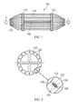
Figure 1 shows a schematic elevational view of a mandrel according to the present invention; -
Figure 2 shows a schematic end view of the mandrel ofFigure 1 with a detail view of the portion of the flange showing the flexible element passing between guide rollers; -
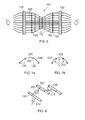
Figure 3a shows a schematic elevational view of a flexible element support frame for use with the mandrel ofFigure 1 ; -
Figure 3b shows a schematic elevational view of an alternative locating portion for use with the support frame ofFigure 3a ; -
Figure 4 shows a partial schematic view of a contractible hoop element for use with the mandrel ofFigure 1 ; -
Figures 5a and 5b show alternative forms of locating the hoop tie ofFigure 4 on the flexible elements of the mandrel ofFigure 1 ; -
Figure 6 shows a schematic elevational view of the mandrel ofFigure 1 together with two support frames and five hoop elements; -
Figures 7a and 7b show partial sectional views of the mandrel ofFigure 1 covered with a heat shrinkable sheet material before and after the pressurisation of the internal volume; -
Figure 8 shows a partial schematic view of a contractible hoop tie for use with the mandrel ofFigure 1 ; and -
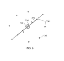
Figure 9 shows a schematic sectional view of the mandrel ofFigure 1 showing a cross tie arrangement. - Referring to
Figures 1 to 5 , a mandrel according to a first embodiment of the invention is designated generally by thereference numeral 100. - The
mandrel 100 comprises first and second flanges 110,120 which are parallel to one another and spaced apart along an axis ofrotation 140 of themandrel 100. The first and second flanges 110,120 are separated from one another by acentral post 150. - A plurality of
flexible elements 130 in the form of braided wire cords extend between the first and second flanges 110,120. Each of the plurality offlexible elements 130 is equispaced around the respective peripheries of the first and second flanges 110,120. - Each of the first and second flanges 110,120 comprises a plurality of
holes 122 around their periphery; eachhole 122 corresponding to a respective one of theflexible elements 130. - After passing through the first and second flanges 110,120, the extremities of each of the
flexible elements 130 are gathered together and connected to a tensioning means (not shown). The tensioning means applies a tensile load T to theflexible elements 130. - In order to minimise the adverse effect of friction between the
flexible elements 130 and the flanges 110,120, a pair ofguide rollers 124 is located at each hole122 with eachflexible element 130 passing between a respective pair of theguide rollers 124. The axis ofrotation 126 of theguide rollers 124 is arranged to be approximately tangential to the flanges 110,120. - Adjustment of the radial position of each of the
flexible elements 130 along the length of themandrel 100 can be achieved by the use of one or more flexible element support frames 160 which are located along thecentral post 150. - Each
support frame 160 comprises asupport frame hub 162 which can be slidably positioned along thecentral post 150 and secured in position by a grub screw (not shown). Extending radially from thesupport frame hub 162 is a plurality ofspokes 164 corresponding to the plurality offlexible elements 130. Astiffening ring 168 is attached to a mid-point of each of thespokes 164. - Each of the
spokes 164 is provided, at its radially outermost end, with a locatingportion 166. Each locatingportion 166 is secured to a respective one of theflexible elements 130. As shown inFigure 3a , the locatingportion 166 takes the form of a U-shaped block which locates against theflexible element 130. In an alternative arrangement, shown inFigure 3b , the locating portion takes the form of a grooved roller element which co-operates with theflexible element 130. - A further means of adjusting the radial position of each of the
flexible elements 130 along the length of themandrel 100 takes the form of acontractible hoop element 170. Thehoop element 170 takes the form of a wire which is connected to each of theflexible elements 130 in a circumferential arrangement with the plane of thehoop element 170 being normal to the axis of rotation of the mandrel140. - In one arrangement, shown in
Figure 5a , thehoop element 170 passes through a reinforcedeyelet 172 positioned in eachflexible element 130. In an alternative arrangement, shown inFigure 5b , thehoop element 170 passes through ahook 174 suspended on a radially inner side of eachflexible element 130. -
Figure 6 shows an example of the use of support frames 160 andhoop elements 170 to radially position theflexible elements 130 as they extend between the first and second flanges 110,120. In the example ofFigure 6 , two support frames 160 and fivehoop elements 170 are used to radially position theflexible elements 130 to thereby define a converging - diverging revolute form. - As shown in
Figures 7a and 7b , the radially outermost surface defined by theflexible elements 130 is covered with a heatshrinkable sheet material 200 which is subsequently shrunk to fit closely over theflexible elements 130 to form a smooth, continuous surface and to thereby define aninternal volume 202. - While the
mandrel 100 can be used in this form to produce a three dimensional hollow component by winding a composite tape of fibre over the radially outer surface defined by theflexible elements 130, this will result in a component having a polygonal or angularinternal surface 206. - The
internal volume 202 can then be pressurised with an inert gas, such as, for example, helium, nitrogen or argon. This pressurisation P of theinternal volume 202 deforms the portions of thesheet material 200 between theflexible elements 130 in a radially outward direction to thus form a smooth, curved,continuous surface 208. - In a second embodiment of the invention, an asymmetric, revolute form may be created by the use of one or more contractible hoop ties 210. Each
hoop tie 210 connects two adjacentflexible elements 130 to one another, as shown inFigure 8 . By applying a tension R to thehoop tie 210, the two respectiveflexible elements 130 can be drawn closer to one another thus creating a local asymmetrical form to themandrel 100. -
Figure 9 shows an alternative means of obtaining an asymmetrical revolute form by the use of one or more contractible cross ties 220. Eachcross tie 220 connects twoflexible elements 130, on opposing sides of thecentral post 150, to one another. As shown inFigure 9 , where the two flanges 110,120 are separated by acentral post 150, thecentral post 150 comprises anaperture 154 therethrough to allow passage of thecross tie 220. - By applying a tension S to the
cross tie 220, the two respectiveflexible elements 130 can be drawn closer to one another thus creating a local asymmetrical form to themandrel 100. - The present invention may be embodied in other specific forms without departing from its essential characteristics. The described embodiments are to be considered in all respects only as illustrative and not restrictive. The scope of the invention is therefore indicated by the appended claims rather than by the foregoing description. All changes which come within the meaning and range of equivalency of the claims are to be embraced within their scope.
Claims (15)
- A mandrel (100) for forming a hollow component from a laminated material comprising:first and second flanges (110,120) spaced apart from one another along an axis (140) of the mandrel (100);a plurality of flexible elements (130) extending between the first and second flanges (110,120); anda means for adjusting the position of each of the flexible elements (130) along the length of the axis (140) of the mandrel (100), such that the plurality of flexible elements (130) define a three-dimensional revolute form.
- A mandrel (100) as claimed in Claim 1, wherein the first and second flanges (110,120) are separated from one another by a central post (150) aligned with the axis (140) of the mandrel (100).
- A mandrel (100) as claimed in Claim 1 or Claim 2, wherein the means for adjusting the position of each of the flexible elements (130) comprises at least one flexible element support frame (160), positionable axially along the axis (140) of the mandrel (100) and having a plurality of locating portions, each of the plurality of locating portions being connected to a respective one of the plurality of flexible elements (130).
- A mandrel (100) as claimed in any one of Claims 1 to 3, wherein the means for adjusting the position of each of the flexible elements (130) further comprises at least one contractible hoop element (170), positionable axially along the axis of the mandrel (100) and connected to each of the plurality of flexible elements (130) in a plane normal to the axis of the mandrel, whereby contraction of the or each hoop element (170) causes each of the plurality of flexible elements (130) to move closer to the axis (140) of the mandrel (100).
- A mandrel (100) as claimed in any one of Claims 1 to 4, wherein the means for adjusting the position of each of the flexible elements (130) further comprises at least one contractible hoop tie (210), positionable axially along the axis of the mandrel (100), the or each hoop tie (210) extending between two adjacent flexible elements (130) in a plane normal to the axis (140) of the mandrel (100), whereby contraction of the or each hoop tie (210) causes the two adjacent flexible elements (130) to move closer to one another.
- A mandrel (100) as claimed in any one of Claims 1 to 5, wherein the means for adjusting the position of each of the flexible elements (130) further comprises at least one contractible cross tie (220), positionable axially along the axis of the mandrel(100) in a plane normal to the axis (140) of the mandrel (100), the or each cross tie (220) extending between two radially opposed flexible elements (130) on opposing sides of the axis (140) of the mandrel (100), whereby contraction of the or each cross tie (220) causes the two radially opposed flexible elements (130) to move closer to one another.
- A mandrel (100) as claimed in any one of Claims 1 to 6, wherein the plurality of flexible elements (130) extends between the first and second flanges (110,120) at an acute angle to the axis (140) of the mandrel (100).
- A mandrel (100) as claimed in any one of Claims 1 to 7, wherein each of the plurality of flexible elements (130) is formed from a material selected from the group comprising steel, stainless steel, aramid, high modulus polyethylene, carbon fibre, silicon, glass fibre, PTFE, PVC and polypropylene.
- A mandrel (100) as claimed in any one of Claims 1 to 8, wherein each of the plurality of flexible elements (130) is coated with a material selected from the group comprising polyamide, PVC, polyethylene, polypropylene, polyvinylidene fluoride and PTFE.
- A mandrel (100) as claimed in any one of Claims 1 to 9, further comprising a heat shrinkable sheet material (200) positioned over a radially outermost surface of the plurality of flexible elements (130) to form a continuous surface, the surface defining an internal volume (202).
- A mandrel (100) as claimed in Claim 10, wherein the internal volume (202)is pressurised with a gas.
- A method of using a mandrel (100) to form a hollow component from a composite laminated material, the mandrel (100) comprising first and second flanges (110,120) spaced apart from one another along an axis (140) of the mandrel (100), the method comprising the steps of:a. positioning at least one flexible element support frame (160) having a plurality of spokes (164), along the axis (140) of the mandrel (100);b. positioning a plurality of flexible elements (130) between the first and second flanges (110,120), each flexible element (130) being supported by a respective one of the spokes (164);c. applying a composite fibre material to a radially outermost surface of the plurality of flexible elements (130);d. curing the composite fibre material to form a composite revolute shell;
ande. releasing the plurality of flexible elements (130) and removing the mandrel (100) from the formed revolute shell. - A method as claimed in Claim 12, wherein step (b) comprises the additional steps of:b'. positioning at least one contractible hoop element (170) connected to each of the plurality of flexible elements (130) along the axis (140) of the mandrel (100), in a plane normal to the axis (140) of the mandrel (100); andb". contracting the hoop element (170) to move each of the plurality of flexible elements (130) towards the axis (140) of the mandrel (100) by a pre-determined distance.
- A method as claimed in Claim 12 or Claim 13, wherein step (c) comprises the additional initial step of:c'. positioning a heat shrinkable sheet material over a radially outermost surface of the plurality of flexible elements (130), the surface defining an internal volume (202); andc". applying heat to the surface of the heat shrinkable sheet material to form a smooth, continuous revolute surface.
- A method as claimed in Claim 14, the method comprising the additional step of:d. pressurising the internal volume (202) with a gas, the gas being selected from the group comprising He, N and Ar.
Applications Claiming Priority (1)
| Application Number | Priority Date | Filing Date | Title |
|---|---|---|---|
| GBGB1121061.4A GB201121061D0 (en) | 2011-12-08 | 2011-12-08 | Apparatus and method for forming a hollow component |
Publications (3)
| Publication Number | Publication Date |
|---|---|
| EP2602082A2 true EP2602082A2 (en) | 2013-06-12 |
| EP2602082A3 EP2602082A3 (en) | 2015-10-28 |
| EP2602082B1 EP2602082B1 (en) | 2017-05-17 |
Family
ID=45541365
Family Applications (1)
| Application Number | Title | Priority Date | Filing Date |
|---|---|---|---|
| EP12190343.9A Not-in-force EP2602082B1 (en) | 2011-12-08 | 2012-10-29 | Apparatus and method for forming a hollow component |
Country Status (3)
| Country | Link |
|---|---|
| US (1) | US8701732B2 (en) |
| EP (1) | EP2602082B1 (en) |
| GB (1) | GB201121061D0 (en) |
Cited By (3)
| Publication number | Priority date | Publication date | Assignee | Title |
|---|---|---|---|---|
| CN110121604A (en) * | 2017-12-06 | 2019-08-13 | 江阴振宏重型锻造有限公司 | A wind turbine main shaft with protective layer and its protective layer attachment process |
| US10399252B2 (en) | 2014-03-01 | 2019-09-03 | Rolls-Royce Plc | Self-heating tool and method of manufacturing a composite component using the same |
| IT201900000951A1 (en) * | 2019-01-22 | 2020-07-22 | People Design S R L | METHOD, GRIPPING ELEMENT, GRIP HEAD AND UNIT FOR THE MODELING OF A SHEET OF FLEXIBLE MATERIAL |
Families Citing this family (4)
| Publication number | Priority date | Publication date | Assignee | Title |
|---|---|---|---|---|
| US10988340B2 (en) * | 2018-03-09 | 2021-04-27 | Advanced Composites, Inc. | Fracking tools and methods of forming the same |
| WO2020107242A1 (en) * | 2018-11-28 | 2020-06-04 | 苏州久美玻璃钢股份有限公司 | Efficient double-yarn-sheet winding machine |
| DE102021109373A1 (en) | 2021-04-14 | 2022-10-20 | Georg Sillner | Process for the manufacture of coreless tubular elements |
| EP4624141A1 (en) * | 2024-03-27 | 2025-10-01 | Airbus Operations GmbH | Manufacturing of fiber-matrix composites components |
Family Cites Families (11)
| Publication number | Priority date | Publication date | Assignee | Title |
|---|---|---|---|---|
| US3080700A (en) * | 1961-01-23 | 1963-03-12 | Rock Island Oil & Refining Co | Apparatus and method for making parallel strand assemblages |
| GB930156A (en) | 1961-03-13 | 1963-07-03 | Ici Ltd | Improvements relating to pressure vessels |
| CH426010A (en) | 1965-11-16 | 1966-12-15 | Landis & Gyr Ag | Winding spool and method of making the same |
| FR2076509A5 (en) * | 1970-01-15 | 1971-10-15 | Paul Gerard | Glass fibre tanks - use of an inflatable core mould allowing withdrawal through a small aperture in the wall |
| DE2124789A1 (en) * | 1971-05-19 | 1972-12-07 | Deutsche Forsch Luft Raumfahrt | Elastomer moulding bladder - reinforced with fibres, to produce reinforced plastic containers of the required size |
| US3975816A (en) | 1974-12-10 | 1976-08-24 | Ershig's, Inc. | Method for making fiber reinforced resin tank forming mandrel |
| GB1537559A (en) | 1976-09-14 | 1978-12-29 | Secr Defence | Methods of fabricating filament-reinforced hollow bodies |
| CH614487A5 (en) * | 1977-02-27 | 1979-11-30 | Roland Frehner | |
| US4983240A (en) | 1987-09-11 | 1991-01-08 | Kamatics Corporation | Method of making a flanged braided bearing |
| US9879440B2 (en) * | 2006-10-11 | 2018-01-30 | Nov North America I/P, Llc | Fiber reinforced resin polymer mortar pole |
| DE102008014380B4 (en) * | 2008-03-17 | 2011-06-30 | EADS Deutschland GmbH, 85521 | Apparatus and method for winding a fiber material on a winding core in the manufacture of a fiber composite component |
-
2011
- 2011-12-08 GB GBGB1121061.4A patent/GB201121061D0/en not_active Ceased
-
2012
- 2012-10-29 EP EP12190343.9A patent/EP2602082B1/en not_active Not-in-force
- 2012-10-30 US US13/663,922 patent/US8701732B2/en active Active
Cited By (4)
| Publication number | Priority date | Publication date | Assignee | Title |
|---|---|---|---|---|
| US10399252B2 (en) | 2014-03-01 | 2019-09-03 | Rolls-Royce Plc | Self-heating tool and method of manufacturing a composite component using the same |
| CN110121604A (en) * | 2017-12-06 | 2019-08-13 | 江阴振宏重型锻造有限公司 | A wind turbine main shaft with protective layer and its protective layer attachment process |
| CN110121604B (en) * | 2017-12-06 | 2021-05-25 | 江阴振宏重型锻造有限公司 | A wind turbine main shaft with protective layer and its protective layer attachment process |
| IT201900000951A1 (en) * | 2019-01-22 | 2020-07-22 | People Design S R L | METHOD, GRIPPING ELEMENT, GRIP HEAD AND UNIT FOR THE MODELING OF A SHEET OF FLEXIBLE MATERIAL |
Also Published As
| Publication number | Publication date |
|---|---|
| GB201121061D0 (en) | 2012-01-18 |
| US8701732B2 (en) | 2014-04-22 |
| EP2602082A3 (en) | 2015-10-28 |
| US20130146210A1 (en) | 2013-06-13 |
| EP2602082B1 (en) | 2017-05-17 |
Similar Documents
| Publication | Publication Date | Title |
|---|---|---|
| US8701732B2 (en) | Apparatus and method for forming a hollow component | |
| US4264278A (en) | Blade or spar | |
| US4273601A (en) | Method for the production of elongated resin impregnated filament composite structures | |
| US8672636B2 (en) | Method for manufacturing braided preforms | |
| US10272302B2 (en) | Fiber-reinforced composite tubular shafts and manufacture thereof | |
| US6510961B1 (en) | Integrally-reinforced braided tubular structure and method of producing the same | |
| US20170066209A1 (en) | Fibre Reinforced Polymer Matrix Composite Pipes | |
| KR19980042411A (en) | Method and apparatus for manufacturing rim preform | |
| CN104185539B (en) | The circular strands of material of fabric prefabricated component for composite component is retrofited | |
| EP2531339B1 (en) | Device and method for producing a fiber composite product | |
| EP2262636B1 (en) | Method of manufacturing a laminated composite item by a winding process, related apparatus and product | |
| CN104169059A (en) | Method and apparatus for forming a fabric preform for a composite material by separately tensioning tows | |
| US20080265656A1 (en) | Wheel, rim and process for manufacturing a wheel | |
| JP2014519995A (en) | Fiber application head having divided compaction rollers | |
| CN104169058B (en) | For compaction pressure being put on the method and apparatus of fabric prefabricated component in winding process | |
| CN112203865B (en) | Method for producing spoke stars from continuous fiber/plastic composite materials | |
| US9975298B2 (en) | Filament winding apparatus | |
| JP2013523488A (en) | Method for manufacturing mechanical member made of composite material with improved mechanical strength of tension and compression and bending | |
| US9981428B2 (en) | Method of manufacturing rim of wheel | |
| US20170225383A1 (en) | Method of manufacturing shaft-shape composite member | |
| US20160298267A1 (en) | Apparatus and method for controlling fabric web | |
| CN103358562B (en) | For manufacturing the constrained system of the sector of the device of airframe | |
| US12539685B2 (en) | Composite structures, forming apparatuses and related systems and methods | |
| US20220242062A1 (en) | Fibre-Reinforced Composite Tubular Shafts and Manufacture Thereof | |
| JP5817275B2 (en) | Manufacturing method and manufacturing apparatus for fiber reinforced plastic |
Legal Events
| Date | Code | Title | Description |
|---|---|---|---|
| PUAI | Public reference made under article 153(3) epc to a published international application that has entered the european phase |
Free format text: ORIGINAL CODE: 0009012 |
|
| AK | Designated contracting states |
Kind code of ref document: A2 Designated state(s): AL AT BE BG CH CY CZ DE DK EE ES FI FR GB GR HR HU IE IS IT LI LT LU LV MC MK MT NL NO PL PT RO RS SE SI SK SM TR |
|
| AX | Request for extension of the european patent |
Extension state: BA ME |
|
| RAP1 | Party data changed (applicant data changed or rights of an application transferred) |
Owner name: ROLLS-ROYCE PLC |
|
| PUAL | Search report despatched |
Free format text: ORIGINAL CODE: 0009013 |
|
| AK | Designated contracting states |
Kind code of ref document: A3 Designated state(s): AL AT BE BG CH CY CZ DE DK EE ES FI FR GB GR HR HU IE IS IT LI LT LU LV MC MK MT NL NO PL PT RO RS SE SI SK SM TR |
|
| AX | Request for extension of the european patent |
Extension state: BA ME |
|
| RIC1 | Information provided on ipc code assigned before grant |
Ipc: B29C 70/30 20060101ALI20150918BHEP Ipc: B29C 33/50 20060101ALI20150918BHEP Ipc: B29L 23/00 20060101ALN20150918BHEP Ipc: B29C 70/32 20060101ALI20150918BHEP Ipc: B29C 33/48 20060101AFI20150918BHEP Ipc: B29L 22/00 20060101ALN20150918BHEP |
|
| 17P | Request for examination filed |
Effective date: 20160427 |
|
| RBV | Designated contracting states (corrected) |
Designated state(s): AL AT BE BG CH CY CZ DE DK EE ES FI FR GB GR HR HU IE IS IT LI LT LU LV MC MK MT NL NO PL PT RO RS SE SI SK SM TR |
|
| GRAP | Despatch of communication of intention to grant a patent |
Free format text: ORIGINAL CODE: EPIDOSNIGR1 |
|
| STAA | Information on the status of an ep patent application or granted ep patent |
Free format text: STATUS: GRANT OF PATENT IS INTENDED |
|
| RIC1 | Information provided on ipc code assigned before grant |
Ipc: B29L 23/00 20060101ALN20170203BHEP Ipc: B29C 70/30 20060101ALI20170203BHEP Ipc: B29C 70/32 20060101ALI20170203BHEP Ipc: B29C 33/48 20060101AFI20170203BHEP Ipc: B29C 33/30 20060101ALI20170203BHEP Ipc: B29C 33/50 20060101ALI20170203BHEP Ipc: B29L 22/00 20060101ALN20170203BHEP |
|
| INTG | Intention to grant announced |
Effective date: 20170224 |
|
| GRAS | Grant fee paid |
Free format text: ORIGINAL CODE: EPIDOSNIGR3 |
|
| GRAA | (expected) grant |
Free format text: ORIGINAL CODE: 0009210 |
|
| STAA | Information on the status of an ep patent application or granted ep patent |
Free format text: STATUS: THE PATENT HAS BEEN GRANTED |
|
| AK | Designated contracting states |
Kind code of ref document: B1 Designated state(s): AL AT BE BG CH CY CZ DE DK EE ES FI FR GB GR HR HU IE IS IT LI LT LU LV MC MK MT NL NO PL PT RO RS SE SI SK SM TR |
|
| REG | Reference to a national code |
Ref country code: GB Ref legal event code: FG4D |
|
| REG | Reference to a national code |
Ref country code: CH Ref legal event code: EP |
|
| REG | Reference to a national code |
Ref country code: IE Ref legal event code: FG4D |
|
| REG | Reference to a national code |
Ref country code: AT Ref legal event code: REF Ref document number: 894063 Country of ref document: AT Kind code of ref document: T Effective date: 20170615 |
|
| REG | Reference to a national code |
Ref country code: DE Ref legal event code: R096 Ref document number: 602012032501 Country of ref document: DE |
|
| REG | Reference to a national code |
Ref country code: NL Ref legal event code: MP Effective date: 20170517 |
|
| REG | Reference to a national code |
Ref country code: LT Ref legal event code: MG4D |
|
| REG | Reference to a national code |
Ref country code: AT Ref legal event code: MK05 Ref document number: 894063 Country of ref document: AT Kind code of ref document: T Effective date: 20170517 |
|
| REG | Reference to a national code |
Ref country code: FR Ref legal event code: PLFP Year of fee payment: 6 |
|
| PG25 | Lapsed in a contracting state [announced via postgrant information from national office to epo] |
Ref country code: LT Free format text: LAPSE BECAUSE OF FAILURE TO SUBMIT A TRANSLATION OF THE DESCRIPTION OR TO PAY THE FEE WITHIN THE PRESCRIBED TIME-LIMIT Effective date: 20170517 Ref country code: GR Free format text: LAPSE BECAUSE OF FAILURE TO SUBMIT A TRANSLATION OF THE DESCRIPTION OR TO PAY THE FEE WITHIN THE PRESCRIBED TIME-LIMIT Effective date: 20170818 Ref country code: NO Free format text: LAPSE BECAUSE OF FAILURE TO SUBMIT A TRANSLATION OF THE DESCRIPTION OR TO PAY THE FEE WITHIN THE PRESCRIBED TIME-LIMIT Effective date: 20170817 Ref country code: ES Free format text: LAPSE BECAUSE OF FAILURE TO SUBMIT A TRANSLATION OF THE DESCRIPTION OR TO PAY THE FEE WITHIN THE PRESCRIBED TIME-LIMIT Effective date: 20170517 Ref country code: AT Free format text: LAPSE BECAUSE OF FAILURE TO SUBMIT A TRANSLATION OF THE DESCRIPTION OR TO PAY THE FEE WITHIN THE PRESCRIBED TIME-LIMIT Effective date: 20170517 Ref country code: FI Free format text: LAPSE BECAUSE OF FAILURE TO SUBMIT A TRANSLATION OF THE DESCRIPTION OR TO PAY THE FEE WITHIN THE PRESCRIBED TIME-LIMIT Effective date: 20170517 Ref country code: HR Free format text: LAPSE BECAUSE OF FAILURE TO SUBMIT A TRANSLATION OF THE DESCRIPTION OR TO PAY THE FEE WITHIN THE PRESCRIBED TIME-LIMIT Effective date: 20170517 |
|
| PG25 | Lapsed in a contracting state [announced via postgrant information from national office to epo] |
Ref country code: NL Free format text: LAPSE BECAUSE OF FAILURE TO SUBMIT A TRANSLATION OF THE DESCRIPTION OR TO PAY THE FEE WITHIN THE PRESCRIBED TIME-LIMIT Effective date: 20170517 Ref country code: BG Free format text: LAPSE BECAUSE OF FAILURE TO SUBMIT A TRANSLATION OF THE DESCRIPTION OR TO PAY THE FEE WITHIN THE PRESCRIBED TIME-LIMIT Effective date: 20170817 Ref country code: PL Free format text: LAPSE BECAUSE OF FAILURE TO SUBMIT A TRANSLATION OF THE DESCRIPTION OR TO PAY THE FEE WITHIN THE PRESCRIBED TIME-LIMIT Effective date: 20170517 Ref country code: IS Free format text: LAPSE BECAUSE OF FAILURE TO SUBMIT A TRANSLATION OF THE DESCRIPTION OR TO PAY THE FEE WITHIN THE PRESCRIBED TIME-LIMIT Effective date: 20170917 Ref country code: SE Free format text: LAPSE BECAUSE OF FAILURE TO SUBMIT A TRANSLATION OF THE DESCRIPTION OR TO PAY THE FEE WITHIN THE PRESCRIBED TIME-LIMIT Effective date: 20170517 Ref country code: LV Free format text: LAPSE BECAUSE OF FAILURE TO SUBMIT A TRANSLATION OF THE DESCRIPTION OR TO PAY THE FEE WITHIN THE PRESCRIBED TIME-LIMIT Effective date: 20170517 Ref country code: RS Free format text: LAPSE BECAUSE OF FAILURE TO SUBMIT A TRANSLATION OF THE DESCRIPTION OR TO PAY THE FEE WITHIN THE PRESCRIBED TIME-LIMIT Effective date: 20170517 |
|
| PG25 | Lapsed in a contracting state [announced via postgrant information from national office to epo] |
Ref country code: RO Free format text: LAPSE BECAUSE OF FAILURE TO SUBMIT A TRANSLATION OF THE DESCRIPTION OR TO PAY THE FEE WITHIN THE PRESCRIBED TIME-LIMIT Effective date: 20170517 Ref country code: CZ Free format text: LAPSE BECAUSE OF FAILURE TO SUBMIT A TRANSLATION OF THE DESCRIPTION OR TO PAY THE FEE WITHIN THE PRESCRIBED TIME-LIMIT Effective date: 20170517 Ref country code: SK Free format text: LAPSE BECAUSE OF FAILURE TO SUBMIT A TRANSLATION OF THE DESCRIPTION OR TO PAY THE FEE WITHIN THE PRESCRIBED TIME-LIMIT Effective date: 20170517 Ref country code: EE Free format text: LAPSE BECAUSE OF FAILURE TO SUBMIT A TRANSLATION OF THE DESCRIPTION OR TO PAY THE FEE WITHIN THE PRESCRIBED TIME-LIMIT Effective date: 20170517 Ref country code: DK Free format text: LAPSE BECAUSE OF FAILURE TO SUBMIT A TRANSLATION OF THE DESCRIPTION OR TO PAY THE FEE WITHIN THE PRESCRIBED TIME-LIMIT Effective date: 20170517 |
|
| REG | Reference to a national code |
Ref country code: DE Ref legal event code: R097 Ref document number: 602012032501 Country of ref document: DE |
|
| PG25 | Lapsed in a contracting state [announced via postgrant information from national office to epo] |
Ref country code: SM Free format text: LAPSE BECAUSE OF FAILURE TO SUBMIT A TRANSLATION OF THE DESCRIPTION OR TO PAY THE FEE WITHIN THE PRESCRIBED TIME-LIMIT Effective date: 20170517 Ref country code: IT Free format text: LAPSE BECAUSE OF FAILURE TO SUBMIT A TRANSLATION OF THE DESCRIPTION OR TO PAY THE FEE WITHIN THE PRESCRIBED TIME-LIMIT Effective date: 20170517 |
|
| PLBE | No opposition filed within time limit |
Free format text: ORIGINAL CODE: 0009261 |
|
| STAA | Information on the status of an ep patent application or granted ep patent |
Free format text: STATUS: NO OPPOSITION FILED WITHIN TIME LIMIT |
|
| 26N | No opposition filed |
Effective date: 20180220 |
|
| PG25 | Lapsed in a contracting state [announced via postgrant information from national office to epo] |
Ref country code: SI Free format text: LAPSE BECAUSE OF FAILURE TO SUBMIT A TRANSLATION OF THE DESCRIPTION OR TO PAY THE FEE WITHIN THE PRESCRIBED TIME-LIMIT Effective date: 20170517 Ref country code: MC Free format text: LAPSE BECAUSE OF FAILURE TO SUBMIT A TRANSLATION OF THE DESCRIPTION OR TO PAY THE FEE WITHIN THE PRESCRIBED TIME-LIMIT Effective date: 20170517 |
|
| REG | Reference to a national code |
Ref country code: CH Ref legal event code: PL |
|
| REG | Reference to a national code |
Ref country code: IE Ref legal event code: MM4A |
|
| PG25 | Lapsed in a contracting state [announced via postgrant information from national office to epo] |
Ref country code: LU Free format text: LAPSE BECAUSE OF NON-PAYMENT OF DUE FEES Effective date: 20171029 Ref country code: LI Free format text: LAPSE BECAUSE OF NON-PAYMENT OF DUE FEES Effective date: 20171031 Ref country code: CH Free format text: LAPSE BECAUSE OF NON-PAYMENT OF DUE FEES Effective date: 20171031 |
|
| REG | Reference to a national code |
Ref country code: BE Ref legal event code: MM Effective date: 20171031 |
|
| PG25 | Lapsed in a contracting state [announced via postgrant information from national office to epo] |
Ref country code: BE Free format text: LAPSE BECAUSE OF NON-PAYMENT OF DUE FEES Effective date: 20171031 |
|
| PG25 | Lapsed in a contracting state [announced via postgrant information from national office to epo] |
Ref country code: MT Free format text: LAPSE BECAUSE OF NON-PAYMENT OF DUE FEES Effective date: 20171029 |
|
| REG | Reference to a national code |
Ref country code: FR Ref legal event code: PLFP Year of fee payment: 7 |
|
| PG25 | Lapsed in a contracting state [announced via postgrant information from national office to epo] |
Ref country code: IE Free format text: LAPSE BECAUSE OF NON-PAYMENT OF DUE FEES Effective date: 20171029 |
|
| PG25 | Lapsed in a contracting state [announced via postgrant information from national office to epo] |
Ref country code: HU Free format text: LAPSE BECAUSE OF FAILURE TO SUBMIT A TRANSLATION OF THE DESCRIPTION OR TO PAY THE FEE WITHIN THE PRESCRIBED TIME-LIMIT; INVALID AB INITIO Effective date: 20121029 |
|
| PG25 | Lapsed in a contracting state [announced via postgrant information from national office to epo] |
Ref country code: CY Free format text: LAPSE BECAUSE OF NON-PAYMENT OF DUE FEES Effective date: 20170517 |
|
| PG25 | Lapsed in a contracting state [announced via postgrant information from national office to epo] |
Ref country code: MK Free format text: LAPSE BECAUSE OF FAILURE TO SUBMIT A TRANSLATION OF THE DESCRIPTION OR TO PAY THE FEE WITHIN THE PRESCRIBED TIME-LIMIT Effective date: 20170517 |
|
| PG25 | Lapsed in a contracting state [announced via postgrant information from national office to epo] |
Ref country code: TR Free format text: LAPSE BECAUSE OF FAILURE TO SUBMIT A TRANSLATION OF THE DESCRIPTION OR TO PAY THE FEE WITHIN THE PRESCRIBED TIME-LIMIT Effective date: 20170517 |
|
| PG25 | Lapsed in a contracting state [announced via postgrant information from national office to epo] |
Ref country code: PT Free format text: LAPSE BECAUSE OF FAILURE TO SUBMIT A TRANSLATION OF THE DESCRIPTION OR TO PAY THE FEE WITHIN THE PRESCRIBED TIME-LIMIT Effective date: 20170517 |
|
| PG25 | Lapsed in a contracting state [announced via postgrant information from national office to epo] |
Ref country code: AL Free format text: LAPSE BECAUSE OF FAILURE TO SUBMIT A TRANSLATION OF THE DESCRIPTION OR TO PAY THE FEE WITHIN THE PRESCRIBED TIME-LIMIT Effective date: 20170517 |
|
| PGFP | Annual fee paid to national office [announced via postgrant information from national office to epo] |
Ref country code: GB Payment date: 20211026 Year of fee payment: 10 Ref country code: DE Payment date: 20211027 Year of fee payment: 10 |
|
| PGFP | Annual fee paid to national office [announced via postgrant information from national office to epo] |
Ref country code: FR Payment date: 20211027 Year of fee payment: 10 |
|
| REG | Reference to a national code |
Ref country code: DE Ref legal event code: R119 Ref document number: 602012032501 Country of ref document: DE |
|
| GBPC | Gb: european patent ceased through non-payment of renewal fee |
Effective date: 20221029 |
|
| P01 | Opt-out of the competence of the unified patent court (upc) registered |
Effective date: 20230528 |
|
| PG25 | Lapsed in a contracting state [announced via postgrant information from national office to epo] |
Ref country code: FR Free format text: LAPSE BECAUSE OF NON-PAYMENT OF DUE FEES Effective date: 20221031 Ref country code: DE Free format text: LAPSE BECAUSE OF NON-PAYMENT OF DUE FEES Effective date: 20230503 |
|
| PG25 | Lapsed in a contracting state [announced via postgrant information from national office to epo] |
Ref country code: GB Free format text: LAPSE BECAUSE OF NON-PAYMENT OF DUE FEES Effective date: 20221029 |