EP2601126B1 - Control of interconnected trolleys - Google Patents
Control of interconnected trolleys Download PDFInfo
- Publication number
- EP2601126B1 EP2601126B1 EP11814156.3A EP11814156A EP2601126B1 EP 2601126 B1 EP2601126 B1 EP 2601126B1 EP 11814156 A EP11814156 A EP 11814156A EP 2601126 B1 EP2601126 B1 EP 2601126B1
- Authority
- EP
- European Patent Office
- Prior art keywords
- hoist trolley
- hoist
- trolley
- speed reference
- ref
- Prior art date
- Legal status (The legal status is an assumption and is not a legal conclusion. Google has not performed a legal analysis and makes no representation as to the accuracy of the status listed.)
- Active
Links
Images

Classifications
-
- B—PERFORMING OPERATIONS; TRANSPORTING
- B66—HOISTING; LIFTING; HAULING
- B66C—CRANES; LOAD-ENGAGING ELEMENTS OR DEVICES FOR CRANES, CAPSTANS, WINCHES, OR TACKLES
- B66C13/00—Other constructional features or details
- B66C13/18—Control systems or devices
- B66C13/22—Control systems or devices for electric drives
-
- B—PERFORMING OPERATIONS; TRANSPORTING
- B66—HOISTING; LIFTING; HAULING
- B66C—CRANES; LOAD-ENGAGING ELEMENTS OR DEVICES FOR CRANES, CAPSTANS, WINCHES, OR TACKLES
- B66C13/00—Other constructional features or details
- B66C13/18—Control systems or devices
- B66C13/22—Control systems or devices for electric drives
- B66C13/30—Circuits for braking, traversing, or slewing motors
-
- B—PERFORMING OPERATIONS; TRANSPORTING
- B66—HOISTING; LIFTING; HAULING
- B66C—CRANES; LOAD-ENGAGING ELEMENTS OR DEVICES FOR CRANES, CAPSTANS, WINCHES, OR TACKLES
- B66C9/00—Travelling gear incorporated in or fitted to trolleys or cranes
- B66C9/14—Trolley or crane travel drives
Definitions
- the invention relates to a hoist trolley assembly according to the preamble of independent claim 1.
- auxiliary lifting apparatus with a faster lifting rate but a lower lifting capacity than that of the main lifting apparatus.
- One way of doing this is to place two lifting machines into the same hoist trolley. This is expensive and requires a special hoist trolley designed for two lifting machines.
- the auxiliary lifting apparatus may be placed in a separate hoist trolley with no drive equipment. This separate hoist trolley is then connected mechanically to the main hoist trolley.
- This solution is expensive and manufacturing-wise poor, because its implementation requires special parts designed exactly for this purpose.
- the order in which the main hoist trolley and the auxiliary hoist trolley without drive equipment are placed on their travel route affects the power supply implementation of the hoist trolleys that is difficult to alter.
- the auxiliary lifting apparatus with a smaller lifting capacity may also be placed in a hoist trolley having its own drive equipment.
- a situation where the auxiliary hoist trolley carries a heavy load generates a problem in this arrangement.
- the torques of the hoist trolley motors are of equal size, the friction of the main hoist trolley wheels is not necessarily enough, and they may start to slip. Slipping may damage both the wheel and the carrier of the wheel, which may be a rail, for instance. In addition any position measurement information is lost, if the position measurement sensor is connected to the slipping wheel.
- the object of the invention is achieved by a hoist trolley assembly which is characterised by what is disclosed in the independent claim. Preferred embodiments of the invention are disclosed in the dependent claims.
- the invention is based on the fact that the control system of the hoist trolley assembly is adapted to generate a final speed reference by utilising the rated torques of the electric motors of the hoist trolleys, the nominal speeds of the hoist trolleys, and the actual values of the total masses of the hoist trolleys.
- the hoist trolley assembly of the invention provides the advantage that the hoist trolley wheels cannot slip even if the load was divided unevenly between the hoist trolleys.
- US 5 803 278 A discloses a hoist trolley assembly according to the preamble of claim 1.
- Figure 1 shows a first hoist trolley 11 and a second hoist trolley 12 that are interconnected such that the first hoist trolley 11 and the second hoist trolley 12 are arranged to move at the same speed.
- the first hoist trolley 11 and the second hoist trolley 12 are arranged to move one after the other.
- the first hoist trolley 11 and the second hoist trolley 12 each comprise four wheels, by means of which the first hoist trolley 11 and the second hoist trolley 12 are arranged to move on rails 80.
- the dead weight of the first hoist trolley 11 is m TA and the load of the first hoist trolley 11 is m LA .
- the dead weight of the second hoist trolley 12 is m TB and the load of the second hoist trolley 12 is m LB .
- the hoist trolley assembly comprises the interconnected hoist trolleys according to Figure 1 , drive equipment for each connected hoist trolley, and the control system according to Figure 2 that is arranged to control the drive equipment of each connected hoist trolley.
- the drive equipment of both the first hoist trolley 11 and the second hoist trolley 12 comprises an electric motor.
- the lifting capacity of the first hoist trolley 11 is substantially higher than that of the second hoist trolley 12.
- the lifting capacity of the first hoist trolley 11 may be 100 tons and that of the second hoist trolley 12 may be 20 tons, for example.
- the control system is arranged to receive information on the location of the interconnected hoist trolleys from a position measurement sensor 114 that is connected to a wheel of the first hoist trolley 11.
- the control system of Figure 2 comprises a programmable logic controller PLC, a first frequency converter FC1, and a second frequency converter FC2.
- the first frequency converter FC1 contains a first restriction block 21 and a first speed controller 31.
- the second frequency converter FC2 contains a second restriction block 22 and a second speed controller 32.
- the programmable logic controller PLC is adapted to receive a preliminary speed reference n ref for the interconnected first 11 and second hoist trolley 12 as well as information on the load m LA of the first hoist trolley 11 and the load m LB of the second hoist trolley 12.
- the programmable logic controller PLC may be adapted to receive the preliminary speed reference n ref for instance from a user interface means, such as control lever that is arranged to be moved by an operator.
- Information on the load m LA of the first hoist trolley 11 and the load m LB of the second hoist trolley 12 may be received from corresponding load sensors, for instance.
- the programmable logic controller PLC is also adapted to store information on the nominal speed v A_nom of the first hoist trolley, the nominal speed v B_nom of the second hoist trolley, the dead weight m TA of the first hoist trolley, the dead weight m TB of the second hoist trolley, the rated torque T A_nom of the first hoist trolley electric motor, the rated torque T B_nom of the second hoist trolley electric motor, the relative value S A_nom of the nominal slip of the first hoist trolley electric motor, the relative value S B_nom of the nominal slip of the second hoist trolley electric motor, this information comprising hoist trolley assembly-specific fixed values.
- the programmable logic controller PLC is adapted to define a load flex coefficient K A for the first hoist trolley.
- the load flex coefficient K B of the second hoist trolley may be freely selected to be 0.02, i.e. 2%, for example.
- the load flex coefficient K B of the second hoist trolley may be a fixed value stored in the programmable logic controller, or it may be a variable, the value of which may be changed by the user.
- the first restriction block 21 of the first frequency converter FC1 is adapted to form a restricted speed reference n rampA for the first hoist trolley by restricting the first time derivative of the preliminary speed reference n refA of the first hoist trolley at its maximum to an acceleration value a rampA of the first restriction block.
- the input signal of the first speed controller 31 is the final speed reference n ref_A_fin for the first hoist trolley 11.
- the first speed controller 31 forms the actual value T A of the first hoist trolley electric motor torque.
- the first frequency converter FC1 comprises a feedback loop.
- the output signal T A of the first speed controller 31, which is also the first output signal of the frequency converter FC1 is fed back in such a manner that the actual value T A of the first hoist trolley electric motor torque is utilized in forming the final speed reference n ref_A_fin of the first hoist trolley.
- the second frequency converter FC2 operates in a corresponding manner as the first frequency converter FC1.
- the second frequency converter FC2 is adapted to form the actual value T B of the second hoist trolley electric motor torque by using as input data the load flex coefficient K B and preliminary speed reference n refB of the second hoist trolley.
- the second restriction block 22 is adapted to form a restricted speed reference n rampB for the second hoist trolley by restricting the first time derivative of the preliminary speed reference n refB of the second hoist trolley at its maximum to an acceleration value a rampB of the second restriction block.
- the input signal of the second speed controller 32 is the final speed reference n ref_B_fin for the second hoist trolley 12, and the output signal of the second speed controller 32 is the actual value T B of the second hoist trolley 12 electric motor torque.
- the acceleration value a r-ampA of the first restriction block is substantially equal to the acceleration value a rampB of the second restriction block.
- Figure 3 is a diagram of the control system of a hoist trolley assembly according to an alternative embodiment of the invention.
- the control system of Figure 3 differs from that of Figure 2 in that the second frequency converter FC2' does not have a feedback loop, that is, the control circuit of the second frequency converter FC2' is an open circuit.
- the features that differ from the control system of Figure 2 are marked with reference numbers equipped with an apostrophe (').
- the programmable logic controller PLC' is adapted to define a preliminary frequency reference f refB ' of the second hoist trolley.
- the second restriction block 22' is adapted to form a restricted frequency reference f rampB ' for the second hoist trolley by restricting the first time derivative of the preliminary frequency reference f refB ' of the second hoist trolley at its maximum to an acceleration value a' rampB of the second restriction block.
- the restricted frequency reference f rampB ' of the second hoist trolley is an input signal of an open circuit controller 32'.
Landscapes
- Engineering & Computer Science (AREA)
- Mechanical Engineering (AREA)
- Automation & Control Theory (AREA)
- Control And Safety Of Cranes (AREA)
Description
- The invention relates to a hoist trolley assembly according to the preamble of independent claim 1.
- It is sometimes necessary to add to a hoist trolley assembly an auxiliary lifting apparatus with a faster lifting rate but a lower lifting capacity than that of the main lifting apparatus. One way of doing this is to place two lifting machines into the same hoist trolley. This is expensive and requires a special hoist trolley designed for two lifting machines. Alternatively, the auxiliary lifting apparatus may be placed in a separate hoist trolley with no drive equipment. This separate hoist trolley is then connected mechanically to the main hoist trolley. This solution is expensive and manufacturing-wise poor, because its implementation requires special parts designed exactly for this purpose. In addition, the order in which the main hoist trolley and the auxiliary hoist trolley without drive equipment are placed on their travel route affects the power supply implementation of the hoist trolleys that is difficult to alter.
- The auxiliary lifting apparatus with a smaller lifting capacity may also be placed in a hoist trolley having its own drive equipment. A situation where the auxiliary hoist trolley carries a heavy load generates a problem in this arrangement. When the torques of the hoist trolley motors are of equal size, the friction of the main hoist trolley wheels is not necessarily enough, and they may start to slip. Slipping may damage both the wheel and the carrier of the wheel, which may be a rail, for instance. In addition any position measurement information is lost, if the position measurement sensor is connected to the slipping wheel.
- It is an object of the invention to provide a hoist trolley assembly comprising interconnected hoist trolleys equipped with their own drive equipment, in which the slipping problem of the hoist trolley wheels caused by unfavourable distribution of loads has been solved. The object of the invention is achieved by a hoist trolley assembly which is characterised by what is disclosed in the independent claim. Preferred embodiments of the invention are disclosed in the dependent claims.
- The invention is based on the fact that the control system of the hoist trolley assembly is adapted to generate a final speed reference by utilising the rated torques of the electric motors of the hoist trolleys, the nominal speeds of the hoist trolleys, and the actual values of the total masses of the hoist trolleys.
- The hoist trolley assembly of the invention provides the advantage that the hoist trolley wheels cannot slip even if the load was divided unevenly between the hoist trolleys.
US 5 803 278 A discloses a hoist trolley assembly according to the preamble of claim 1. - The invention will now be described in greater detail by means of preferred embodiments and with reference to the accompanying drawings, in which:
-
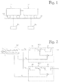
Figure 1 shows interconnected hoist trolleys; -
Figure 2 is a diagram of the control system of a hoist trolley assembly according to an embodiment of the invention; and -
Figure 3 is a diagram of the control system of a hoist trolley assembly according to another embodiment of the invention. -
Figure 1 shows afirst hoist trolley 11 and asecond hoist trolley 12 that are interconnected such that thefirst hoist trolley 11 and thesecond hoist trolley 12 are arranged to move at the same speed. Thefirst hoist trolley 11 and thesecond hoist trolley 12 are arranged to move one after the other. Thefirst hoist trolley 11 and thesecond hoist trolley 12 each comprise four wheels, by means of which thefirst hoist trolley 11 and thesecond hoist trolley 12 are arranged to move onrails 80. The dead weight of thefirst hoist trolley 11 is mTA and the load of thefirst hoist trolley 11 is mLA. The dead weight of thesecond hoist trolley 12 is mTB and the load of thesecond hoist trolley 12 is mLB. - According to an embodiment of the invention, the hoist trolley assembly comprises the interconnected hoist trolleys according to
Figure 1 , drive equipment for each connected hoist trolley, and the control system according toFigure 2 that is arranged to control the drive equipment of each connected hoist trolley. The drive equipment of both thefirst hoist trolley 11 and thesecond hoist trolley 12 comprises an electric motor. The lifting capacity of thefirst hoist trolley 11 is substantially higher than that of thesecond hoist trolley 12. The lifting capacity of thefirst hoist trolley 11 may be 100 tons and that of thesecond hoist trolley 12 may be 20 tons, for example. The control system is arranged to receive information on the location of the interconnected hoist trolleys from aposition measurement sensor 114 that is connected to a wheel of thefirst hoist trolley 11. - The control system of
Figure 2 comprises a programmable logic controller PLC, a first frequency converter FC1, and a second frequency converter FC2. The first frequency converter FC1 contains afirst restriction block 21 and afirst speed controller 31. The second frequency converter FC2 contains asecond restriction block 22 and asecond speed controller 32. - The programmable logic controller PLC is adapted to receive a preliminary speed reference nref for the interconnected first 11 and
second hoist trolley 12 as well as information on the load mLA of thefirst hoist trolley 11 and the load mLB of thesecond hoist trolley 12. The programmable logic controller PLC may be adapted to receive the preliminary speed reference nref for instance from a user interface means, such as control lever that is arranged to be moved by an operator. Information on the load mLA of thefirst hoist trolley 11 and the load mLB of thesecond hoist trolley 12 may be received from corresponding load sensors, for instance. - The programmable logic controller PLC is also adapted to store information on the nominal speed vA_nom of the first hoist trolley, the nominal speed vB_nom of the second hoist trolley, the dead weight mTA of the first hoist trolley, the dead weight mTB of the second hoist trolley, the rated torque TA_nom of the first hoist trolley electric motor, the rated torque TB_nom of the second hoist trolley electric motor, the relative value SA_nom of the nominal slip of the first hoist trolley electric motor, the relative value SB_nom of the nominal slip of the second hoist trolley electric motor, this information comprising hoist trolley assembly-specific fixed values.
- The programmable logic controller PLC is adapted to define a preliminary speed reference nrefA of the first hoist trolley on the basis of the nominal speed vA_nom of the first hoist trolley, the nominal speed vB_nom of the second hoist trolley and the preliminary speed reference nref by using the equation


- In addition to the preliminary speed references nrefA and nrefB, the programmable logic controller PLC is adapted to define a load flex coefficient KA for the first hoist trolley. The load flex coefficient KB of the second hoist trolley may be freely selected to be 0.02, i.e. 2%, for example. The load flex coefficient KB of the second hoist trolley may be a fixed value stored in the programmable logic controller, or it may be a variable, the value of which may be changed by the user. The load flex coefficient KA of the first hoist trolley is defined by
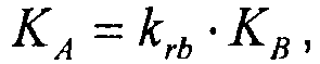

- The
first restriction block 21 of the first frequency converter FC1 is adapted to form a restricted speed reference nrampA for the first hoist trolley by restricting the first time derivative of the preliminary speed reference nrefA of the first hoist trolley at its maximum to an acceleration value arampA of the first restriction block. - The input signal of the
first speed controller 31 is the final speed reference nref_A_fin for thefirst hoist trolley 11. On the basis of its input signal, thefirst speed controller 31 forms the actual value TA of the first hoist trolley electric motor torque. The control system is adapted to form a final speed reference nref_A_fin for thefirst hoist trolley 11 by using the equation

- In accordance with the above equation, the first frequency converter FC1 comprises a feedback loop. The output signal TA of the
first speed controller 31, which is also the first output signal of the frequency converter FC1, is fed back in such a manner that the actual value TA of the first hoist trolley electric motor torque is utilized in forming the final speed reference nref_A_fin of the first hoist trolley. - The second frequency converter FC2 operates in a corresponding manner as the first frequency converter FC1. The second frequency converter FC2 is adapted to form the actual value TB of the second hoist trolley electric motor torque by using as input data the load flex coefficient KB and preliminary speed reference nrefB of the second hoist trolley.
- The
second restriction block 22 is adapted to form a restricted speed reference nrampB for the second hoist trolley by restricting the first time derivative of the preliminary speed reference nrefB of the second hoist trolley at its maximum to an acceleration value arampB of the second restriction block. The input signal of thesecond speed controller 32 is the final speed reference nref_B_fin for thesecond hoist trolley 12, and the output signal of thesecond speed controller 32 is the actual value TB of thesecond hoist trolley 12 electric motor torque. The control system is adapted to form a final speed reference nref_B_fin for thesecond hoist trolley 12 by using the equation
- In an embodiment of the invention, the acceleration value ar-ampA of the first restriction block is substantially equal to the acceleration value arampB of the second restriction block. In an alternative embodiment, the acceleration value arampA of the first restriction block is dependent on the acceleration value arampB of the second restriction block as shown in the equation below.

-
Figure 3 is a diagram of the control system of a hoist trolley assembly according to an alternative embodiment of the invention. The control system ofFigure 3 differs from that ofFigure 2 in that the second frequency converter FC2' does not have a feedback loop, that is, the control circuit of the second frequency converter FC2' is an open circuit. InFigure 3 , the features that differ from the control system ofFigure 2 are marked with reference numbers equipped with an apostrophe ('). - The programmable logic controller PLC' is adapted to define a preliminary frequency reference frefB' of the second hoist trolley. The second restriction block 22' is adapted to form a restricted frequency reference frampB' for the second hoist trolley by restricting the first time derivative of the preliminary frequency reference frefB' of the second hoist trolley at its maximum to an acceleration value a'rampB of the second restriction block. The restricted frequency reference frampB' of the second hoist trolley is an input signal of an open circuit controller 32'.
- It is obvious to a person skilled in the art that the basic idea of the invention may be implemented in many different ways. The invention and its embodiments are thus not restricted to the examples described above but may vary within the scope of the claims.
Claims (8)
- A hoist trolley assembly that comprises a first hoist trolley (11), drive equipment for the first hoist trolley, a second hoist trolley (12), drive equipment for the second hoist trolley, and a control system, the first hoist trolley (11) being connected to the second hoist trolley (12) in such a manner that the first hoist trolley (11) and the second hoist trolley (12) are arranged to move at the same speed, both the drive equipment of the first hoist trolley and the drive equipment of the second hoist trolley comprising an electric motor, the control system being adapted to receive a preliminary speed reference (nref) for the interconnected first hoist trolley (11) and second hoist trolley (12), to form a final speed reference (nref_Afin) for the first hoist trolley (11) by using initial data that comprise the preliminary speed reference (nref), and to control the electric motor of the first hoist trolley (11) with the final speed reference (nref_Afin) for the first hoist trolley (11), characterised in that the control system is adapted to store information on the rated torque TA_nom of the electric motor of the first hoist trolley, the rated torque TB_nom of the electric motor of the second hoist trolley, nominal speed vA_nom of the first hoist trolley, nominal speed vB_nom of the second hoist trolley, dead weight mTA of the first hoist trolley, and dead weight mTB of the second hoist trolley, the control system is adapted to receive information on a load mLA of the first hoist trolley and a load mLB of the second hoist trolley, and the control system is adapted to form a hoist trolley coefficient krb obtainable from

- A hoist trolley assembly as claimed in claim 1, characterised in that the control system comprises a programmable logic controller (PLC) and a first restriction block (21), the programmable logic controller (PLC) being adapted to form a preliminary speed reference nrefA for the first hoist trolley by using the following equation

- A hoist trolley assembly as claimed in claim 2, characterised in that the programmable logic controller (PLC) is also adapted to form a preliminary speed reference nrefB for the second hoist trolley by using the following equation

- A hoist trolley assembly as claimed in claim 3, characterised in that the acceleration value arampA of the first restriction block is substantially equal to the acceleration value arampB of the second restriction block.
- A hoist trolley assembly as claimed in any one of claims 2 to 4, characterised in that the control system is adapted to form a final speed reference nref_A_fin for the first hoist trolley (11) by using the equation
 nrampA = restricted speed reference of the first hoist trolleykrb = hoist trolley coefficientKB = load flex coefficient of the second hoist trolleyTA = actual value of the first hoist trolley electric motor torque.
 - A hoist trolley assembly as claimed in any one of claims 2 to 4, characterised in that the control system is adapted to form a final speed reference nref_A_fin for the first hoist trolley (11) by using the equation
 nrampA = restricted speed reference of the first hoist trolleykrb = hoist trolley coefficientsB = nominal slip of the second hoist trolley short-circuit motor as a relative valueTA = actual value of the first hoist trolley electric motor torque.
 - A hoist trolley assembly as claimed in any preceding claim, characterised in that the hoist trolley assembly also comprises a position measurement sensor (114) that is connected to at least one wheel of the first hoist trolley (11) and adapted to transmit data on the position of the inter-connected hoist trolleys to the control system.
- A hoist trolley assembly as claimed in any preceding claim, characterised in that the lifting capacity of the first hoist trolley (11) is substantially higher than that of the second hoist trolley (12).
Applications Claiming Priority (2)
| Application Number | Priority Date | Filing Date | Title |
|---|---|---|---|
| FI20105838A FI123931B (en) | 2010-08-05 | 2010-08-05 | Lifting carriage assembly |
| PCT/FI2011/050669 WO2012017131A1 (en) | 2010-08-05 | 2011-07-21 | Control of interconnected trolleys |
Publications (3)
| Publication Number | Publication Date |
|---|---|
| EP2601126A1 EP2601126A1 (en) | 2013-06-12 |
| EP2601126A4 EP2601126A4 (en) | 2014-09-03 |
| EP2601126B1 true EP2601126B1 (en) | 2016-04-13 |
Family
ID=42669345
Family Applications (1)
| Application Number | Title | Priority Date | Filing Date |
|---|---|---|---|
| EP11814156.3A Active EP2601126B1 (en) | 2010-08-05 | 2011-07-21 | Control of interconnected trolleys |
Country Status (5)
| Country | Link |
|---|---|
| US (1) | US8751074B2 (en) |
| EP (1) | EP2601126B1 (en) |
| CN (1) | CN103068715B (en) |
| FI (1) | FI123931B (en) |
| WO (1) | WO2012017131A1 (en) |
Families Citing this family (2)
| Publication number | Priority date | Publication date | Assignee | Title |
|---|---|---|---|---|
| EP2868674B1 (en) | 2013-10-30 | 2019-11-20 | 3M Innovative Properties Company | Peroxide curable fluoropolymers obtainable by polymerization using non-fluorinated polyhydroxy emulsifiers |
| US10279823B2 (en) * | 2016-08-08 | 2019-05-07 | General Electric Company | System for controlling or monitoring a vehicle system along a route |
Family Cites Families (13)
| Publication number | Priority date | Publication date | Assignee | Title |
|---|---|---|---|---|
| JPS51126566U (en) * | 1975-04-08 | 1976-10-13 | ||
| JPS51126566A (en) | 1975-04-25 | 1976-11-04 | Junjiro Sakagami | Method for filtering minute particles |
| JPS5439800Y2 (en) * | 1975-08-07 | 1979-11-24 | ||
| JPH07277672A (en) | 1994-04-01 | 1995-10-24 | Ishikawajima Materials Handling Equip Co Ltd | Method and device for preventing meandering of overhead crane |
| TW312680B (en) * | 1995-09-08 | 1997-08-11 | Murata Machinery Ltd | |
| FR2743058B1 (en) * | 1995-12-27 | 1998-01-30 | Schneider Electric Sa | ANTI-SKIDING DEVICE FOR A LIFT TRUCK |
| FI100594B (en) | 1996-09-13 | 1998-01-15 | Kci Kone Cranes Internat Oy | A system for controlling a device, such as a crane jetty, which moves on wheels on rails |
| DE19723372A1 (en) * | 1997-06-04 | 1998-12-10 | Braeutigam Ruhrthaler Transpor | Battery powered trolley |
| DE10103635A1 (en) | 2001-01-27 | 2002-08-22 | Noell Crane Sys Gmbh | Wheel load-dependent torque control of a travel drive |
| JP4207229B2 (en) | 2006-09-06 | 2009-01-14 | 村田機械株式会社 | Traveling cart |
| JP2009057148A (en) | 2007-08-31 | 2009-03-19 | Mitsubishi Heavy Ind Ltd | Idling preventing control device for trolley |
| CN101618832B (en) * | 2008-07-02 | 2013-05-15 | 哈尔滨理工大学 | Intelligent track system for handling and assembly of large parts |
| US8428796B2 (en) * | 2008-10-17 | 2013-04-23 | Frank Wegner Donnelly | Rail conveyance system for mining |
-
2010
- 2010-08-05 FI FI20105838A patent/FI123931B/en not_active IP Right Cessation
-
2011
- 2011-07-21 EP EP11814156.3A patent/EP2601126B1/en active Active
- 2011-07-21 US US13/811,557 patent/US8751074B2/en active Active
- 2011-07-21 WO PCT/FI2011/050669 patent/WO2012017131A1/en not_active Ceased
- 2011-07-21 CN CN201180038521.0A patent/CN103068715B/en active Active
Also Published As
| Publication number | Publication date |
|---|---|
| EP2601126A1 (en) | 2013-06-12 |
| FI20105838A7 (en) | 2012-02-06 |
| EP2601126A4 (en) | 2014-09-03 |
| US20130118373A1 (en) | 2013-05-16 |
| FI20105838A0 (en) | 2010-08-05 |
| US8751074B2 (en) | 2014-06-10 |
| CN103068715B (en) | 2015-09-09 |
| CN103068715A (en) | 2013-04-24 |
| FI123931B (en) | 2013-12-31 |
| WO2012017131A1 (en) | 2012-02-09 |
Similar Documents
| Publication | Publication Date | Title |
|---|---|---|
| EP3078537B1 (en) | Electric vehicle control device and electric vehicle control method | |
| EP3078539B1 (en) | Control device for electric vehicle and control method for electric vehicle | |
| AU2010256020B2 (en) | Energy-saving operation of rail vehicles having at least two drive units | |
| KR101369650B1 (en) | Vehicle status display apparatus of hybrid vehicle | |
| US9440556B2 (en) | Anti-skid control device for a vehicle having an electromotive drive system | |
| EP1731467A1 (en) | Control device of elevator | |
| CN107601312B (en) | Lifting mechanism hybrid power system and its control method, crane | |
| US20100256848A1 (en) | Drive assist device and method for motor driven truck | |
| EP3251906B1 (en) | Vehicle control device and vehicle control method | |
| MODE | DYNAMIC OPTIMIZATION OF A MINE | |
| CN103496326A (en) | Vehicle-mounted energy storing device and method for electric locomotive and electric vehicle set | |
| US20160101700A1 (en) | Control system and method for a vehicle | |
| US9428079B2 (en) | Electric vehicle | |
| JP2013531959A (en) | Method for energy-optimized operation of a floorbound large transport vehicle that can be run with rubber tires and has an electric travel drive | |
| EP2879902B1 (en) | Optimized control of the operation of one or more traction systems of a train for entering and exiting from a coasting condition | |
| US8751074B2 (en) | Control of interconnected trolleys | |
| JP2012017189A (en) | Traveling vehicle system | |
| JP6686452B2 (en) | Electric vehicle control device and electric vehicle control method | |
| EP2891596A1 (en) | Self-balancing mobile body and control method for same | |
| CN109017826A (en) | A kind of braking method and brake apparatus of tooth rail car | |
| CN100566128C (en) | Control device for AC rotating electrical machine and control method for AC rotating electrical machine | |
| CN104444829B (en) | Intelligent collision-proof system and intelligent collision-proof method of crane | |
| JP6291671B2 (en) | Vehicle control device | |
| EP1943178B1 (en) | Vehicle and method for propulsion control of a vehicle | |
| CN106080557A (en) | A kind of Remote Control Automatic BAS and method |
Legal Events
| Date | Code | Title | Description |
|---|---|---|---|
| PUAI | Public reference made under article 153(3) epc to a published international application that has entered the european phase |
Free format text: ORIGINAL CODE: 0009012 |
|
| 17P | Request for examination filed |
Effective date: 20130111 |
|
| AK | Designated contracting states |
Kind code of ref document: A1 Designated state(s): AL AT BE BG CH CY CZ DE DK EE ES FI FR GB GR HR HU IE IS IT LI LT LU LV MC MK MT NL NO PL PT RO RS SE SI SK SM TR |
|
| DAX | Request for extension of the european patent (deleted) | ||
| A4 | Supplementary search report drawn up and despatched |
Effective date: 20140805 |
|
| RIC1 | Information provided on ipc code assigned before grant |
Ipc: B66C 9/14 20060101AFI20140730BHEP Ipc: B66C 13/30 20060101ALI20140730BHEP |
|
| GRAP | Despatch of communication of intention to grant a patent |
Free format text: ORIGINAL CODE: EPIDOSNIGR1 |
|
| INTG | Intention to grant announced |
Effective date: 20150715 |
|
| INTG | Intention to grant announced |
Effective date: 20151127 |
|
| INTG | Intention to grant announced |
Effective date: 20151202 |
|
| INTG | Intention to grant announced |
Effective date: 20151210 |
|
| INTG | Intention to grant announced |
Effective date: 20151217 |
|
| RAP1 | Party data changed (applicant data changed or rights of an application transferred) |
Owner name: KONECRANES GLOBAL CORPORATION |
|
| GRAS | Grant fee paid |
Free format text: ORIGINAL CODE: EPIDOSNIGR3 |
|
| GRAA | (expected) grant |
Free format text: ORIGINAL CODE: 0009210 |
|
| AK | Designated contracting states |
Kind code of ref document: B1 Designated state(s): AL AT BE BG CH CY CZ DE DK EE ES FI FR GB GR HR HU IE IS IT LI LT LU LV MC MK MT NL NO PL PT RO RS SE SI SK SM TR |
|
| REG | Reference to a national code |
Ref country code: GB Ref legal event code: FG4D |
|
| REG | Reference to a national code |
Ref country code: AT Ref legal event code: REF Ref document number: 789902 Country of ref document: AT Kind code of ref document: T Effective date: 20160415 Ref country code: CH Ref legal event code: EP |
|
| REG | Reference to a national code |
Ref country code: IE Ref legal event code: FG4D |
|
| REG | Reference to a national code |
Ref country code: DE Ref legal event code: R096 Ref document number: 602011025369 Country of ref document: DE |
|
| REG | Reference to a national code |
Ref country code: FR Ref legal event code: PLFP Year of fee payment: 6 |
|
| REG | Reference to a national code |
Ref country code: LT Ref legal event code: MG4D |
|
| REG | Reference to a national code |
Ref country code: AT Ref legal event code: MK05 Ref document number: 789902 Country of ref document: AT Kind code of ref document: T Effective date: 20160413 |
|
| REG | Reference to a national code |
Ref country code: NL Ref legal event code: MP Effective date: 20160413 |
|
| PG25 | Lapsed in a contracting state [announced via postgrant information from national office to epo] |
Ref country code: NL Free format text: LAPSE BECAUSE OF FAILURE TO SUBMIT A TRANSLATION OF THE DESCRIPTION OR TO PAY THE FEE WITHIN THE PRESCRIBED TIME-LIMIT Effective date: 20160413 Ref country code: LT Free format text: LAPSE BECAUSE OF FAILURE TO SUBMIT A TRANSLATION OF THE DESCRIPTION OR TO PAY THE FEE WITHIN THE PRESCRIBED TIME-LIMIT Effective date: 20160413 Ref country code: PL Free format text: LAPSE BECAUSE OF FAILURE TO SUBMIT A TRANSLATION OF THE DESCRIPTION OR TO PAY THE FEE WITHIN THE PRESCRIBED TIME-LIMIT Effective date: 20160413 Ref country code: FI Free format text: LAPSE BECAUSE OF FAILURE TO SUBMIT A TRANSLATION OF THE DESCRIPTION OR TO PAY THE FEE WITHIN THE PRESCRIBED TIME-LIMIT Effective date: 20160413 Ref country code: NO Free format text: LAPSE BECAUSE OF FAILURE TO SUBMIT A TRANSLATION OF THE DESCRIPTION OR TO PAY THE FEE WITHIN THE PRESCRIBED TIME-LIMIT Effective date: 20160713 |
|
| PG25 | Lapsed in a contracting state [announced via postgrant information from national office to epo] |
Ref country code: RS Free format text: LAPSE BECAUSE OF FAILURE TO SUBMIT A TRANSLATION OF THE DESCRIPTION OR TO PAY THE FEE WITHIN THE PRESCRIBED TIME-LIMIT Effective date: 20160413 Ref country code: GR Free format text: LAPSE BECAUSE OF FAILURE TO SUBMIT A TRANSLATION OF THE DESCRIPTION OR TO PAY THE FEE WITHIN THE PRESCRIBED TIME-LIMIT Effective date: 20160714 Ref country code: PT Free format text: LAPSE BECAUSE OF FAILURE TO SUBMIT A TRANSLATION OF THE DESCRIPTION OR TO PAY THE FEE WITHIN THE PRESCRIBED TIME-LIMIT Effective date: 20160816 Ref country code: HR Free format text: LAPSE BECAUSE OF FAILURE TO SUBMIT A TRANSLATION OF THE DESCRIPTION OR TO PAY THE FEE WITHIN THE PRESCRIBED TIME-LIMIT Effective date: 20160413 Ref country code: ES Free format text: LAPSE BECAUSE OF FAILURE TO SUBMIT A TRANSLATION OF THE DESCRIPTION OR TO PAY THE FEE WITHIN THE PRESCRIBED TIME-LIMIT Effective date: 20160413 Ref country code: SE Free format text: LAPSE BECAUSE OF FAILURE TO SUBMIT A TRANSLATION OF THE DESCRIPTION OR TO PAY THE FEE WITHIN THE PRESCRIBED TIME-LIMIT Effective date: 20160413 Ref country code: AT Free format text: LAPSE BECAUSE OF FAILURE TO SUBMIT A TRANSLATION OF THE DESCRIPTION OR TO PAY THE FEE WITHIN THE PRESCRIBED TIME-LIMIT Effective date: 20160413 Ref country code: LV Free format text: LAPSE BECAUSE OF FAILURE TO SUBMIT A TRANSLATION OF THE DESCRIPTION OR TO PAY THE FEE WITHIN THE PRESCRIBED TIME-LIMIT Effective date: 20160413 |
|
| PG25 | Lapsed in a contracting state [announced via postgrant information from national office to epo] |
Ref country code: BE Free format text: LAPSE BECAUSE OF FAILURE TO SUBMIT A TRANSLATION OF THE DESCRIPTION OR TO PAY THE FEE WITHIN THE PRESCRIBED TIME-LIMIT Effective date: 20160413 Ref country code: IT Free format text: LAPSE BECAUSE OF FAILURE TO SUBMIT A TRANSLATION OF THE DESCRIPTION OR TO PAY THE FEE WITHIN THE PRESCRIBED TIME-LIMIT Effective date: 20160413 |
|
| REG | Reference to a national code |
Ref country code: DE Ref legal event code: R097 Ref document number: 602011025369 Country of ref document: DE |
|
| PG25 | Lapsed in a contracting state [announced via postgrant information from national office to epo] |
Ref country code: DK Free format text: LAPSE BECAUSE OF FAILURE TO SUBMIT A TRANSLATION OF THE DESCRIPTION OR TO PAY THE FEE WITHIN THE PRESCRIBED TIME-LIMIT Effective date: 20160413 Ref country code: EE Free format text: LAPSE BECAUSE OF FAILURE TO SUBMIT A TRANSLATION OF THE DESCRIPTION OR TO PAY THE FEE WITHIN THE PRESCRIBED TIME-LIMIT Effective date: 20160413 Ref country code: SK Free format text: LAPSE BECAUSE OF FAILURE TO SUBMIT A TRANSLATION OF THE DESCRIPTION OR TO PAY THE FEE WITHIN THE PRESCRIBED TIME-LIMIT Effective date: 20160413 Ref country code: CZ Free format text: LAPSE BECAUSE OF FAILURE TO SUBMIT A TRANSLATION OF THE DESCRIPTION OR TO PAY THE FEE WITHIN THE PRESCRIBED TIME-LIMIT Effective date: 20160413 Ref country code: RO Free format text: LAPSE BECAUSE OF FAILURE TO SUBMIT A TRANSLATION OF THE DESCRIPTION OR TO PAY THE FEE WITHIN THE PRESCRIBED TIME-LIMIT Effective date: 20160413 |
|
| PLBE | No opposition filed within time limit |
Free format text: ORIGINAL CODE: 0009261 |
|
| STAA | Information on the status of an ep patent application or granted ep patent |
Free format text: STATUS: NO OPPOSITION FILED WITHIN TIME LIMIT |
|
| PG25 | Lapsed in a contracting state [announced via postgrant information from national office to epo] |
Ref country code: SM Free format text: LAPSE BECAUSE OF FAILURE TO SUBMIT A TRANSLATION OF THE DESCRIPTION OR TO PAY THE FEE WITHIN THE PRESCRIBED TIME-LIMIT Effective date: 20160413 |
|
| REG | Reference to a national code |
Ref country code: CH Ref legal event code: PL |
|
| 26N | No opposition filed |
Effective date: 20170116 |
|
| PG25 | Lapsed in a contracting state [announced via postgrant information from national office to epo] |
Ref country code: MC Free format text: LAPSE BECAUSE OF FAILURE TO SUBMIT A TRANSLATION OF THE DESCRIPTION OR TO PAY THE FEE WITHIN THE PRESCRIBED TIME-LIMIT Effective date: 20160413 |
|
| PG25 | Lapsed in a contracting state [announced via postgrant information from national office to epo] |
Ref country code: LI Free format text: LAPSE BECAUSE OF NON-PAYMENT OF DUE FEES Effective date: 20160731 Ref country code: CH Free format text: LAPSE BECAUSE OF NON-PAYMENT OF DUE FEES Effective date: 20160731 |
|
| REG | Reference to a national code |
Ref country code: IE Ref legal event code: MM4A |
|
| PG25 | Lapsed in a contracting state [announced via postgrant information from national office to epo] |
Ref country code: SI Free format text: LAPSE BECAUSE OF FAILURE TO SUBMIT A TRANSLATION OF THE DESCRIPTION OR TO PAY THE FEE WITHIN THE PRESCRIBED TIME-LIMIT Effective date: 20160413 |
|
| REG | Reference to a national code |
Ref country code: FR Ref legal event code: PLFP Year of fee payment: 7 |
|
| PG25 | Lapsed in a contracting state [announced via postgrant information from national office to epo] |
Ref country code: IE Free format text: LAPSE BECAUSE OF NON-PAYMENT OF DUE FEES Effective date: 20160721 |
|
| PG25 | Lapsed in a contracting state [announced via postgrant information from national office to epo] |
Ref country code: LU Free format text: LAPSE BECAUSE OF NON-PAYMENT OF DUE FEES Effective date: 20160721 |
|
| PG25 | Lapsed in a contracting state [announced via postgrant information from national office to epo] |
Ref country code: CY Free format text: LAPSE BECAUSE OF FAILURE TO SUBMIT A TRANSLATION OF THE DESCRIPTION OR TO PAY THE FEE WITHIN THE PRESCRIBED TIME-LIMIT Effective date: 20160413 Ref country code: HU Free format text: LAPSE BECAUSE OF FAILURE TO SUBMIT A TRANSLATION OF THE DESCRIPTION OR TO PAY THE FEE WITHIN THE PRESCRIBED TIME-LIMIT; INVALID AB INITIO Effective date: 20110721 |
|
| PG25 | Lapsed in a contracting state [announced via postgrant information from national office to epo] |
Ref country code: IS Free format text: LAPSE BECAUSE OF FAILURE TO SUBMIT A TRANSLATION OF THE DESCRIPTION OR TO PAY THE FEE WITHIN THE PRESCRIBED TIME-LIMIT Effective date: 20160413 Ref country code: MK Free format text: LAPSE BECAUSE OF FAILURE TO SUBMIT A TRANSLATION OF THE DESCRIPTION OR TO PAY THE FEE WITHIN THE PRESCRIBED TIME-LIMIT Effective date: 20160413 Ref country code: MT Free format text: LAPSE BECAUSE OF NON-PAYMENT OF DUE FEES Effective date: 20160731 Ref country code: TR Free format text: LAPSE BECAUSE OF FAILURE TO SUBMIT A TRANSLATION OF THE DESCRIPTION OR TO PAY THE FEE WITHIN THE PRESCRIBED TIME-LIMIT Effective date: 20160413 |
|
| REG | Reference to a national code |
Ref country code: FR Ref legal event code: PLFP Year of fee payment: 8 |
|
| PG25 | Lapsed in a contracting state [announced via postgrant information from national office to epo] |
Ref country code: BG Free format text: LAPSE BECAUSE OF FAILURE TO SUBMIT A TRANSLATION OF THE DESCRIPTION OR TO PAY THE FEE WITHIN THE PRESCRIBED TIME-LIMIT Effective date: 20160413 |
|
| PG25 | Lapsed in a contracting state [announced via postgrant information from national office to epo] |
Ref country code: AL Free format text: LAPSE BECAUSE OF FAILURE TO SUBMIT A TRANSLATION OF THE DESCRIPTION OR TO PAY THE FEE WITHIN THE PRESCRIBED TIME-LIMIT Effective date: 20160413 |
|
| P01 | Opt-out of the competence of the unified patent court (upc) registered |
Effective date: 20230428 |
|
| PGFP | Annual fee paid to national office [announced via postgrant information from national office to epo] |
Ref country code: DE Payment date: 20250722 Year of fee payment: 15 |
|
| PGFP | Annual fee paid to national office [announced via postgrant information from national office to epo] |
Ref country code: GB Payment date: 20250724 Year of fee payment: 15 |
|
| PGFP | Annual fee paid to national office [announced via postgrant information from national office to epo] |
Ref country code: FR Payment date: 20250723 Year of fee payment: 15 |