EP2601046B1 - Packaging container made of a sheet-like composite with improved adhesion-layer and inner-layer combination - Google Patents
Packaging container made of a sheet-like composite with improved adhesion-layer and inner-layer combination Download PDFInfo
- Publication number
- EP2601046B1 EP2601046B1 EP11754984.0A EP11754984A EP2601046B1 EP 2601046 B1 EP2601046 B1 EP 2601046B1 EP 11754984 A EP11754984 A EP 11754984A EP 2601046 B1 EP2601046 B1 EP 2601046B1
- Authority
- EP
- European Patent Office
- Prior art keywords
- layer
- container
- composite
- polymer
- adhesive layer
- Prior art date
- Legal status (The legal status is an assumption and is not a legal conclusion. Google has not performed a legal analysis and makes no representation as to the accuracy of the status listed.)
- Active
Links
- 239000002131 composite material Substances 0.000 title claims description 105
- 238000004806 packaging method and process Methods 0.000 title description 4
- 239000010410 layer Substances 0.000 claims description 403
- 229920000642 polymer Polymers 0.000 claims description 145
- 239000012790 adhesive layer Substances 0.000 claims description 71
- 230000004888 barrier function Effects 0.000 claims description 65
- 238000000034 method Methods 0.000 claims description 46
- 239000000155 melt Substances 0.000 claims description 31
- 239000011888 foil Substances 0.000 claims description 21
- 238000004519 manufacturing process Methods 0.000 claims description 18
- 229920001169 thermoplastic Polymers 0.000 claims description 18
- QVGXLLKOCUKJST-UHFFFAOYSA-N atomic oxygen Chemical compound [O] QVGXLLKOCUKJST-UHFFFAOYSA-N 0.000 claims description 13
- 229910052760 oxygen Inorganic materials 0.000 claims description 13
- 239000001301 oxygen Substances 0.000 claims description 13
- 238000007669 thermal treatment Methods 0.000 claims description 13
- 239000000203 mixture Substances 0.000 claims description 12
- 239000007789 gas Substances 0.000 claims description 9
- 229910052751 metal Inorganic materials 0.000 claims description 9
- 239000002184 metal Substances 0.000 claims description 9
- 239000011248 coating agent Substances 0.000 claims description 7
- 238000000576 coating method Methods 0.000 claims description 7
- 230000005674 electromagnetic induction Effects 0.000 claims description 7
- 239000012968 metallocene catalyst Substances 0.000 claims description 7
- 229920000098 polyolefin Polymers 0.000 claims description 7
- 239000011111 cardboard Substances 0.000 claims description 5
- 239000011087 paperboard Substances 0.000 claims description 5
- UZMKOEWHQQPOBJ-UHFFFAOYSA-M sodium;2,3-dihydroxypropane-1-sulfonate Chemical compound [Na+].OCC(O)CS([O-])(=O)=O UZMKOEWHQQPOBJ-UHFFFAOYSA-M 0.000 claims description 5
- 239000000126 substance Substances 0.000 claims description 4
- 238000002604 ultrasonography Methods 0.000 claims description 4
- 238000007599 discharging Methods 0.000 claims 2
- 239000010408 film Substances 0.000 claims 2
- 239000011104 metalized film Substances 0.000 claims 1
- 238000002156 mixing Methods 0.000 claims 1
- 239000011343 solid material Substances 0.000 claims 1
- 235000013305 food Nutrition 0.000 description 34
- 239000002243 precursor Substances 0.000 description 29
- 229920003023 plastic Polymers 0.000 description 28
- 239000004033 plastic Substances 0.000 description 28
- -1 polyethylene Polymers 0.000 description 23
- 238000003475 lamination Methods 0.000 description 18
- 239000004698 Polyethylene Substances 0.000 description 15
- 229920000573 polyethylene Polymers 0.000 description 15
- 229910052782 aluminium Inorganic materials 0.000 description 14
- XAGFODPZIPBFFR-UHFFFAOYSA-N aluminium Chemical compound [Al] XAGFODPZIPBFFR-UHFFFAOYSA-N 0.000 description 14
- 238000002844 melting Methods 0.000 description 13
- 230000008018 melting Effects 0.000 description 13
- 238000007789 sealing Methods 0.000 description 13
- 239000004952 Polyamide Substances 0.000 description 12
- 229920002647 polyamide Polymers 0.000 description 12
- 239000011521 glass Substances 0.000 description 11
- VGGSQFUCUMXWEO-UHFFFAOYSA-N Ethene Chemical compound C=C VGGSQFUCUMXWEO-UHFFFAOYSA-N 0.000 description 9
- 229920000219 Ethylene vinyl alcohol Polymers 0.000 description 9
- UFRKOOWSQGXVKV-UHFFFAOYSA-N ethene;ethenol Chemical compound C=C.OC=C UFRKOOWSQGXVKV-UHFFFAOYSA-N 0.000 description 8
- 239000004715 ethylene vinyl alcohol Substances 0.000 description 8
- 238000011282 treatment Methods 0.000 description 8
- 238000011049 filling Methods 0.000 description 7
- 238000010438 heat treatment Methods 0.000 description 7
- 238000004026 adhesive bonding Methods 0.000 description 6
- 229920001684 low density polyethylene Polymers 0.000 description 6
- 239000004702 low-density polyethylene Substances 0.000 description 6
- 229920001155 polypropylene Polymers 0.000 description 6
- 206010053648 Vascular occlusion Diseases 0.000 description 5
- 239000002318 adhesion promoter Substances 0.000 description 5
- 238000001125 extrusion Methods 0.000 description 5
- 239000007788 liquid Substances 0.000 description 5
- 239000000463 material Substances 0.000 description 5
- 230000005855 radiation Effects 0.000 description 5
- 239000007787 solid Substances 0.000 description 5
- 239000004743 Polypropylene Substances 0.000 description 4
- 150000001252 acrylic acid derivatives Chemical class 0.000 description 4
- 230000005540 biological transmission Effects 0.000 description 4
- 238000001816 cooling Methods 0.000 description 4
- 230000006378 damage Effects 0.000 description 4
- 230000008569 process Effects 0.000 description 4
- 239000004416 thermosoftening plastic Substances 0.000 description 4
- 229920000089 Cyclic olefin copolymer Polymers 0.000 description 3
- 239000005977 Ethylene Substances 0.000 description 3
- 238000005520 cutting process Methods 0.000 description 3
- 230000035622 drinking Effects 0.000 description 3
- 230000005670 electromagnetic radiation Effects 0.000 description 3
- 235000021149 fatty food Nutrition 0.000 description 3
- 239000000835 fiber Substances 0.000 description 3
- 229920001903 high density polyethylene Polymers 0.000 description 3
- 239000004700 high-density polyethylene Substances 0.000 description 3
- 229910003480 inorganic solid Inorganic materials 0.000 description 3
- 239000010902 straw Substances 0.000 description 3
- 229920001187 thermosetting polymer Polymers 0.000 description 3
- 230000003313 weakening effect Effects 0.000 description 3
- SMZOUWXMTYCWNB-UHFFFAOYSA-N 2-(2-methoxy-5-methylphenyl)ethanamine Chemical compound COC1=CC=C(C)C=C1CCN SMZOUWXMTYCWNB-UHFFFAOYSA-N 0.000 description 2
- BLDFSDCBQJUWFG-UHFFFAOYSA-N 2-(methylamino)-1,2-diphenylethanol Chemical compound C=1C=CC=CC=1C(NC)C(O)C1=CC=CC=C1 BLDFSDCBQJUWFG-UHFFFAOYSA-N 0.000 description 2
- NIXOWILDQLNWCW-UHFFFAOYSA-N 2-Propenoic acid Natural products OC(=O)C=C NIXOWILDQLNWCW-UHFFFAOYSA-N 0.000 description 2
- 238000012371 Aseptic Filling Methods 0.000 description 2
- VTYYLEPIZMXCLO-UHFFFAOYSA-L Calcium carbonate Chemical compound [Ca+2].[O-]C([O-])=O VTYYLEPIZMXCLO-UHFFFAOYSA-L 0.000 description 2
- 239000004713 Cyclic olefin copolymer Substances 0.000 description 2
- 241001465754 Metazoa Species 0.000 description 2
- QAOWNCQODCNURD-UHFFFAOYSA-N Sulfuric acid Chemical compound OS(O)(=O)=O QAOWNCQODCNURD-UHFFFAOYSA-N 0.000 description 2
- GWEVSGVZZGPLCZ-UHFFFAOYSA-N Titan oxide Chemical compound O=[Ti]=O GWEVSGVZZGPLCZ-UHFFFAOYSA-N 0.000 description 2
- 208000027418 Wounds and injury Diseases 0.000 description 2
- 239000002998 adhesive polymer Substances 0.000 description 2
- 244000052616 bacterial pathogen Species 0.000 description 2
- 230000015572 biosynthetic process Effects 0.000 description 2
- 150000001244 carboxylic acid anhydrides Chemical class 0.000 description 2
- 150000001875 compounds Chemical class 0.000 description 2
- 238000007334 copolymerization reaction Methods 0.000 description 2
- 230000001419 dependent effect Effects 0.000 description 2
- 238000013461 design Methods 0.000 description 2
- 239000006185 dispersion Substances 0.000 description 2
- 230000000694 effects Effects 0.000 description 2
- 238000005265 energy consumption Methods 0.000 description 2
- 229920006242 ethylene acrylic acid copolymer Polymers 0.000 description 2
- 238000007765 extrusion coating Methods 0.000 description 2
- 125000000524 functional group Chemical group 0.000 description 2
- 238000005227 gel permeation chromatography Methods 0.000 description 2
- 229920000578 graft copolymer Polymers 0.000 description 2
- 208000014674 injury Diseases 0.000 description 2
- 239000011256 inorganic filler Substances 0.000 description 2
- 229910003475 inorganic filler Inorganic materials 0.000 description 2
- 238000010030 laminating Methods 0.000 description 2
- 229920000092 linear low density polyethylene Polymers 0.000 description 2
- 239000004707 linear low-density polyethylene Substances 0.000 description 2
- FPYJFEHAWHCUMM-UHFFFAOYSA-N maleic anhydride Chemical compound O=C1OC(=O)C=C1 FPYJFEHAWHCUMM-UHFFFAOYSA-N 0.000 description 2
- 229920001179 medium density polyethylene Polymers 0.000 description 2
- 239000004701 medium-density polyethylene Substances 0.000 description 2
- 238000000465 moulding Methods 0.000 description 2
- 239000002365 multiple layer Substances 0.000 description 2
- 239000000123 paper Substances 0.000 description 2
- 238000002360 preparation method Methods 0.000 description 2
- 238000004321 preservation Methods 0.000 description 2
- 238000012545 processing Methods 0.000 description 2
- 238000004080 punching Methods 0.000 description 2
- 230000009467 reduction Effects 0.000 description 2
- 230000001954 sterilising effect Effects 0.000 description 2
- 238000004659 sterilization and disinfection Methods 0.000 description 2
- 238000003860 storage Methods 0.000 description 2
- 239000012815 thermoplastic material Substances 0.000 description 2
- 229920001817 Agar Polymers 0.000 description 1
- 229920006045 Akulon® Polymers 0.000 description 1
- 229920003313 Bynel® Polymers 0.000 description 1
- OYPRJOBELJOOCE-UHFFFAOYSA-N Calcium Chemical compound [Ca] OYPRJOBELJOOCE-UHFFFAOYSA-N 0.000 description 1
- 235000007466 Corylus avellana Nutrition 0.000 description 1
- 240000007582 Corylus avellana Species 0.000 description 1
- 241000065675 Cyclops Species 0.000 description 1
- 229920006055 Durethan® Polymers 0.000 description 1
- 240000003517 Elaeocarpus dentatus Species 0.000 description 1
- 241000196324 Embryophyta Species 0.000 description 1
- 229920006060 Grivory® Polymers 0.000 description 1
- 101000576320 Homo sapiens Max-binding protein MNT Proteins 0.000 description 1
- 206010061245 Internal injury Diseases 0.000 description 1
- FYYHWMGAXLPEAU-UHFFFAOYSA-N Magnesium Chemical compound [Mg] FYYHWMGAXLPEAU-UHFFFAOYSA-N 0.000 description 1
- CERQOIWHTDAKMF-UHFFFAOYSA-N Methacrylic acid Chemical compound CC(=C)C(O)=O CERQOIWHTDAKMF-UHFFFAOYSA-N 0.000 description 1
- FAIIFDPAEUKBEP-UHFFFAOYSA-N Nilvadipine Chemical compound COC(=O)C1=C(C#N)NC(C)=C(C(=O)OC(C)C)C1C1=CC=CC([N+]([O-])=O)=C1 FAIIFDPAEUKBEP-UHFFFAOYSA-N 0.000 description 1
- 229920003298 Nucrel® Polymers 0.000 description 1
- 229920006121 Polyxylylene adipamide Polymers 0.000 description 1
- 241001312297 Selar Species 0.000 description 1
- 229920003365 Selar® Polymers 0.000 description 1
- 229920006097 Ultramide® Polymers 0.000 description 1
- 238000005299 abrasion Methods 0.000 description 1
- 150000001253 acrylic acids Chemical class 0.000 description 1
- 239000000853 adhesive Substances 0.000 description 1
- 230000001070 adhesive effect Effects 0.000 description 1
- 229920006020 amorphous polyamide Polymers 0.000 description 1
- 238000000149 argon plasma sintering Methods 0.000 description 1
- 229910052788 barium Inorganic materials 0.000 description 1
- DSAJWYNOEDNPEQ-UHFFFAOYSA-N barium atom Chemical compound [Ba] DSAJWYNOEDNPEQ-UHFFFAOYSA-N 0.000 description 1
- 238000005452 bending Methods 0.000 description 1
- 229910052791 calcium Inorganic materials 0.000 description 1
- 239000011575 calcium Substances 0.000 description 1
- 229910000019 calcium carbonate Inorganic materials 0.000 description 1
- 235000014171 carbonated beverage Nutrition 0.000 description 1
- 150000004649 carbonic acid derivatives Chemical class 0.000 description 1
- 230000008859 change Effects 0.000 description 1
- 239000003795 chemical substances by application Substances 0.000 description 1
- 239000000470 constituent Substances 0.000 description 1
- 238000010276 construction Methods 0.000 description 1
- 229920001577 copolymer Polymers 0.000 description 1
- 230000007797 corrosion Effects 0.000 description 1
- 238000005260 corrosion Methods 0.000 description 1
- 238000005336 cracking Methods 0.000 description 1
- LDHQCZJRKDOVOX-NSCUHMNNSA-N crotonic acid Chemical compound C\C=C\C(O)=O LDHQCZJRKDOVOX-NSCUHMNNSA-N 0.000 description 1
- 235000013365 dairy product Nutrition 0.000 description 1
- 230000006735 deficit Effects 0.000 description 1
- 230000008021 deposition Effects 0.000 description 1
- 238000009826 distribution Methods 0.000 description 1
- 235000013399 edible fruits Nutrition 0.000 description 1
- JBKVHLHDHHXQEQ-UHFFFAOYSA-N epsilon-caprolactam Chemical compound O=C1CCCCCN1 JBKVHLHDHHXQEQ-UHFFFAOYSA-N 0.000 description 1
- 238000010096 film blowing Methods 0.000 description 1
- 238000009472 formulation Methods 0.000 description 1
- 239000012634 fragment Substances 0.000 description 1
- 235000011389 fruit/vegetable juice Nutrition 0.000 description 1
- 239000004519 grease Substances 0.000 description 1
- 230000003760 hair shine Effects 0.000 description 1
- 229910052736 halogen Inorganic materials 0.000 description 1
- 150000002367 halogens Chemical class 0.000 description 1
- 238000009998 heat setting Methods 0.000 description 1
- 230000006872 improvement Effects 0.000 description 1
- 238000013532 laser treatment Methods 0.000 description 1
- 229960000869 magnesium oxide Drugs 0.000 description 1
- 239000000395 magnesium oxide Substances 0.000 description 1
- CPLXHLVBOLITMK-UHFFFAOYSA-N magnesium oxide Inorganic materials [Mg]=O CPLXHLVBOLITMK-UHFFFAOYSA-N 0.000 description 1
- 235000012245 magnesium oxide Nutrition 0.000 description 1
- 150000002739 metals Chemical class 0.000 description 1
- 239000002245 particle Substances 0.000 description 1
- 238000009832 plasma treatment Methods 0.000 description 1
- 230000010287 polarization Effects 0.000 description 1
- 125000003367 polycyclic group Chemical group 0.000 description 1
- 229920002959 polymer blend Polymers 0.000 description 1
- 238000006116 polymerization reaction Methods 0.000 description 1
- 238000007639 printing Methods 0.000 description 1
- 239000010453 quartz Substances 0.000 description 1
- 238000010791 quenching Methods 0.000 description 1
- 230000000171 quenching effect Effects 0.000 description 1
- 239000002994 raw material Substances 0.000 description 1
- 238000004064 recycling Methods 0.000 description 1
- 229920005989 resin Polymers 0.000 description 1
- 239000011347 resin Substances 0.000 description 1
- 150000003839 salts Chemical class 0.000 description 1
- 235000015067 sauces Nutrition 0.000 description 1
- 238000000926 separation method Methods 0.000 description 1
- 238000005029 sieve analysis Methods 0.000 description 1
- VYPSYNLAJGMNEJ-UHFFFAOYSA-N silicon dioxide Inorganic materials O=[Si]=O VYPSYNLAJGMNEJ-UHFFFAOYSA-N 0.000 description 1
- 239000002356 single layer Substances 0.000 description 1
- 239000002689 soil Substances 0.000 description 1
- 238000007711 solidification Methods 0.000 description 1
- 230000008023 solidification Effects 0.000 description 1
- 210000002023 somite Anatomy 0.000 description 1
- 235000014347 soups Nutrition 0.000 description 1
- 150000003467 sulfuric acid derivatives Chemical class 0.000 description 1
- 235000013616 tea Nutrition 0.000 description 1
- 238000010998 test method Methods 0.000 description 1
- 238000001931 thermography Methods 0.000 description 1
- 239000005028 tinplate Substances 0.000 description 1
- 239000004408 titanium dioxide Substances 0.000 description 1
- LDHQCZJRKDOVOX-UHFFFAOYSA-N trans-crotonic acid Natural products CC=CC(O)=O LDHQCZJRKDOVOX-UHFFFAOYSA-N 0.000 description 1
- 238000003466 welding Methods 0.000 description 1
Images


Classifications
-
- B—PERFORMING OPERATIONS; TRANSPORTING
- B65—CONVEYING; PACKING; STORING; HANDLING THIN OR FILAMENTARY MATERIAL
- B65D—CONTAINERS FOR STORAGE OR TRANSPORT OF ARTICLES OR MATERIALS, e.g. BAGS, BARRELS, BOTTLES, BOXES, CANS, CARTONS, CRATES, DRUMS, JARS, TANKS, HOPPERS, FORWARDING CONTAINERS; ACCESSORIES, CLOSURES, OR FITTINGS THEREFOR; PACKAGING ELEMENTS; PACKAGES
- B65D81/00—Containers, packaging elements, or packages, for contents presenting particular transport or storage problems, or adapted to be used for non-packaging purposes after removal of contents
- B65D81/34—Containers, packaging elements, or packages, for contents presenting particular transport or storage problems, or adapted to be used for non-packaging purposes after removal of contents for packaging foodstuffs or other articles intended to be cooked or heated within the package
-
- B—PERFORMING OPERATIONS; TRANSPORTING
- B29—WORKING OF PLASTICS; WORKING OF SUBSTANCES IN A PLASTIC STATE IN GENERAL
- B29D—PRODUCING PARTICULAR ARTICLES FROM PLASTICS OR FROM SUBSTANCES IN A PLASTIC STATE
- B29D22/00—Producing hollow articles
- B29D22/003—Containers for packaging, storing or transporting, e.g. bottles, jars, cans, barrels, tanks
-
- B—PERFORMING OPERATIONS; TRANSPORTING
- B32—LAYERED PRODUCTS
- B32B—LAYERED PRODUCTS, i.e. PRODUCTS BUILT-UP OF STRATA OF FLAT OR NON-FLAT, e.g. CELLULAR OR HONEYCOMB, FORM
- B32B15/00—Layered products comprising a layer of metal
- B32B15/04—Layered products comprising a layer of metal comprising metal as the main or only constituent of a layer, which is next to another layer of the same or of a different material
- B32B15/08—Layered products comprising a layer of metal comprising metal as the main or only constituent of a layer, which is next to another layer of the same or of a different material of synthetic resin
-
- B—PERFORMING OPERATIONS; TRANSPORTING
- B32—LAYERED PRODUCTS
- B32B—LAYERED PRODUCTS, i.e. PRODUCTS BUILT-UP OF STRATA OF FLAT OR NON-FLAT, e.g. CELLULAR OR HONEYCOMB, FORM
- B32B15/00—Layered products comprising a layer of metal
- B32B15/20—Layered products comprising a layer of metal comprising aluminium or copper
-
- B—PERFORMING OPERATIONS; TRANSPORTING
- B32—LAYERED PRODUCTS
- B32B—LAYERED PRODUCTS, i.e. PRODUCTS BUILT-UP OF STRATA OF FLAT OR NON-FLAT, e.g. CELLULAR OR HONEYCOMB, FORM
- B32B27/00—Layered products comprising a layer of synthetic resin
- B32B27/06—Layered products comprising a layer of synthetic resin as the main or only constituent of a layer, which is next to another layer of the same or of a different material
- B32B27/08—Layered products comprising a layer of synthetic resin as the main or only constituent of a layer, which is next to another layer of the same or of a different material of synthetic resin
-
- B—PERFORMING OPERATIONS; TRANSPORTING
- B32—LAYERED PRODUCTS
- B32B—LAYERED PRODUCTS, i.e. PRODUCTS BUILT-UP OF STRATA OF FLAT OR NON-FLAT, e.g. CELLULAR OR HONEYCOMB, FORM
- B32B27/00—Layered products comprising a layer of synthetic resin
- B32B27/06—Layered products comprising a layer of synthetic resin as the main or only constituent of a layer, which is next to another layer of the same or of a different material
- B32B27/10—Layered products comprising a layer of synthetic resin as the main or only constituent of a layer, which is next to another layer of the same or of a different material of paper or cardboard
-
- B—PERFORMING OPERATIONS; TRANSPORTING
- B32—LAYERED PRODUCTS
- B32B—LAYERED PRODUCTS, i.e. PRODUCTS BUILT-UP OF STRATA OF FLAT OR NON-FLAT, e.g. CELLULAR OR HONEYCOMB, FORM
- B32B27/00—Layered products comprising a layer of synthetic resin
- B32B27/32—Layered products comprising a layer of synthetic resin comprising polyolefins
- B32B27/322—Layered products comprising a layer of synthetic resin comprising polyolefins comprising halogenated polyolefins, e.g. PTFE
-
- B—PERFORMING OPERATIONS; TRANSPORTING
- B32—LAYERED PRODUCTS
- B32B—LAYERED PRODUCTS, i.e. PRODUCTS BUILT-UP OF STRATA OF FLAT OR NON-FLAT, e.g. CELLULAR OR HONEYCOMB, FORM
- B32B27/00—Layered products comprising a layer of synthetic resin
- B32B27/32—Layered products comprising a layer of synthetic resin comprising polyolefins
- B32B27/327—Layered products comprising a layer of synthetic resin comprising polyolefins comprising polyolefins obtained by a metallocene or single-site catalyst
-
- B—PERFORMING OPERATIONS; TRANSPORTING
- B32—LAYERED PRODUCTS
- B32B—LAYERED PRODUCTS, i.e. PRODUCTS BUILT-UP OF STRATA OF FLAT OR NON-FLAT, e.g. CELLULAR OR HONEYCOMB, FORM
- B32B27/00—Layered products comprising a layer of synthetic resin
- B32B27/34—Layered products comprising a layer of synthetic resin comprising polyamides
-
- B—PERFORMING OPERATIONS; TRANSPORTING
- B32—LAYERED PRODUCTS
- B32B—LAYERED PRODUCTS, i.e. PRODUCTS BUILT-UP OF STRATA OF FLAT OR NON-FLAT, e.g. CELLULAR OR HONEYCOMB, FORM
- B32B29/00—Layered products comprising a layer of paper or cardboard
- B32B29/002—Layered products comprising a layer of paper or cardboard as the main or only constituent of a layer, which is next to another layer of the same or of a different material
-
- B—PERFORMING OPERATIONS; TRANSPORTING
- B65—CONVEYING; PACKING; STORING; HANDLING THIN OR FILAMENTARY MATERIAL
- B65D—CONTAINERS FOR STORAGE OR TRANSPORT OF ARTICLES OR MATERIALS, e.g. BAGS, BARRELS, BOTTLES, BOXES, CANS, CARTONS, CRATES, DRUMS, JARS, TANKS, HOPPERS, FORWARDING CONTAINERS; ACCESSORIES, CLOSURES, OR FITTINGS THEREFOR; PACKAGING ELEMENTS; PACKAGES
- B65D5/00—Rigid or semi-rigid containers of polygonal cross-section, e.g. boxes, cartons or trays, formed by folding or erecting one or more blanks made of paper
- B65D5/02—Rigid or semi-rigid containers of polygonal cross-section, e.g. boxes, cartons or trays, formed by folding or erecting one or more blanks made of paper by folding or erecting a single blank to form a tubular body with or without subsequent folding operations, or the addition of separate elements, to close the ends of the body
- B65D5/06—Rigid or semi-rigid containers of polygonal cross-section, e.g. boxes, cartons or trays, formed by folding or erecting one or more blanks made of paper by folding or erecting a single blank to form a tubular body with or without subsequent folding operations, or the addition of separate elements, to close the ends of the body with end-closing or contents-supporting elements formed by folding inwardly a wall extending from, and continuously around, an end of the tubular body
- B65D5/064—Rectangular containers having a body with gusset-flaps folded outwardly or adhered to the side or the top of the container
- B65D5/065—Rectangular containers having a body with gusset-flaps folded outwardly or adhered to the side or the top of the container with supplemental means facilitating the opening, e.g. tear lines, tear tabs
-
- B—PERFORMING OPERATIONS; TRANSPORTING
- B65—CONVEYING; PACKING; STORING; HANDLING THIN OR FILAMENTARY MATERIAL
- B65D—CONTAINERS FOR STORAGE OR TRANSPORT OF ARTICLES OR MATERIALS, e.g. BAGS, BARRELS, BOTTLES, BOXES, CANS, CARTONS, CRATES, DRUMS, JARS, TANKS, HOPPERS, FORWARDING CONTAINERS; ACCESSORIES, CLOSURES, OR FITTINGS THEREFOR; PACKAGING ELEMENTS; PACKAGES
- B65D5/00—Rigid or semi-rigid containers of polygonal cross-section, e.g. boxes, cartons or trays, formed by folding or erecting one or more blanks made of paper
- B65D5/42—Details of containers or of foldable or erectable container blanks
- B65D5/72—Contents-dispensing means
- B65D5/74—Spouts
- B65D5/746—Spouts formed separately from the container
- B65D5/747—Spouts formed separately from the container with means for piercing or cutting the container wall or a membrane connected to said wall
-
- B—PERFORMING OPERATIONS; TRANSPORTING
- B32—LAYERED PRODUCTS
- B32B—LAYERED PRODUCTS, i.e. PRODUCTS BUILT-UP OF STRATA OF FLAT OR NON-FLAT, e.g. CELLULAR OR HONEYCOMB, FORM
- B32B2255/00—Coating on the layer surface
- B32B2255/10—Coating on the layer surface on synthetic resin layer or on natural or synthetic rubber layer
-
- B—PERFORMING OPERATIONS; TRANSPORTING
- B32—LAYERED PRODUCTS
- B32B—LAYERED PRODUCTS, i.e. PRODUCTS BUILT-UP OF STRATA OF FLAT OR NON-FLAT, e.g. CELLULAR OR HONEYCOMB, FORM
- B32B2255/00—Coating on the layer surface
- B32B2255/20—Inorganic coating
- B32B2255/205—Metallic coating
-
- B—PERFORMING OPERATIONS; TRANSPORTING
- B32—LAYERED PRODUCTS
- B32B—LAYERED PRODUCTS, i.e. PRODUCTS BUILT-UP OF STRATA OF FLAT OR NON-FLAT, e.g. CELLULAR OR HONEYCOMB, FORM
- B32B2264/00—Composition or properties of particles which form a particulate layer or are present as additives
- B32B2264/10—Inorganic particles
- B32B2264/101—Glass
-
- B—PERFORMING OPERATIONS; TRANSPORTING
- B32—LAYERED PRODUCTS
- B32B—LAYERED PRODUCTS, i.e. PRODUCTS BUILT-UP OF STRATA OF FLAT OR NON-FLAT, e.g. CELLULAR OR HONEYCOMB, FORM
- B32B2264/00—Composition or properties of particles which form a particulate layer or are present as additives
- B32B2264/10—Inorganic particles
- B32B2264/102—Oxide or hydroxide
-
- B—PERFORMING OPERATIONS; TRANSPORTING
- B32—LAYERED PRODUCTS
- B32B—LAYERED PRODUCTS, i.e. PRODUCTS BUILT-UP OF STRATA OF FLAT OR NON-FLAT, e.g. CELLULAR OR HONEYCOMB, FORM
- B32B2264/00—Composition or properties of particles which form a particulate layer or are present as additives
- B32B2264/10—Inorganic particles
- B32B2264/104—Oxysalt, e.g. carbonate, sulfate, phosphate or nitrate particles
-
- B—PERFORMING OPERATIONS; TRANSPORTING
- B32—LAYERED PRODUCTS
- B32B—LAYERED PRODUCTS, i.e. PRODUCTS BUILT-UP OF STRATA OF FLAT OR NON-FLAT, e.g. CELLULAR OR HONEYCOMB, FORM
- B32B2307/00—Properties of the layers or laminate
- B32B2307/50—Properties of the layers or laminate having particular mechanical properties
- B32B2307/514—Oriented
- B32B2307/516—Oriented mono-axially
-
- B—PERFORMING OPERATIONS; TRANSPORTING
- B32—LAYERED PRODUCTS
- B32B—LAYERED PRODUCTS, i.e. PRODUCTS BUILT-UP OF STRATA OF FLAT OR NON-FLAT, e.g. CELLULAR OR HONEYCOMB, FORM
- B32B2307/00—Properties of the layers or laminate
- B32B2307/50—Properties of the layers or laminate having particular mechanical properties
- B32B2307/554—Wear resistance
-
- B—PERFORMING OPERATIONS; TRANSPORTING
- B32—LAYERED PRODUCTS
- B32B—LAYERED PRODUCTS, i.e. PRODUCTS BUILT-UP OF STRATA OF FLAT OR NON-FLAT, e.g. CELLULAR OR HONEYCOMB, FORM
- B32B2307/00—Properties of the layers or laminate
- B32B2307/70—Other properties
- B32B2307/72—Density
-
- B—PERFORMING OPERATIONS; TRANSPORTING
- B32—LAYERED PRODUCTS
- B32B—LAYERED PRODUCTS, i.e. PRODUCTS BUILT-UP OF STRATA OF FLAT OR NON-FLAT, e.g. CELLULAR OR HONEYCOMB, FORM
- B32B2307/00—Properties of the layers or laminate
- B32B2307/70—Other properties
- B32B2307/724—Permeability to gases, adsorption
- B32B2307/7242—Non-permeable
- B32B2307/7244—Oxygen barrier
-
- B—PERFORMING OPERATIONS; TRANSPORTING
- B32—LAYERED PRODUCTS
- B32B—LAYERED PRODUCTS, i.e. PRODUCTS BUILT-UP OF STRATA OF FLAT OR NON-FLAT, e.g. CELLULAR OR HONEYCOMB, FORM
- B32B2307/00—Properties of the layers or laminate
- B32B2307/70—Other properties
- B32B2307/732—Dimensional properties
-
- B—PERFORMING OPERATIONS; TRANSPORTING
- B32—LAYERED PRODUCTS
- B32B—LAYERED PRODUCTS, i.e. PRODUCTS BUILT-UP OF STRATA OF FLAT OR NON-FLAT, e.g. CELLULAR OR HONEYCOMB, FORM
- B32B2307/00—Properties of the layers or laminate
- B32B2307/70—Other properties
- B32B2307/746—Slipping, anti-blocking, low friction
-
- B—PERFORMING OPERATIONS; TRANSPORTING
- B32—LAYERED PRODUCTS
- B32B—LAYERED PRODUCTS, i.e. PRODUCTS BUILT-UP OF STRATA OF FLAT OR NON-FLAT, e.g. CELLULAR OR HONEYCOMB, FORM
- B32B2307/00—Properties of the layers or laminate
- B32B2307/70—Other properties
- B32B2307/75—Printability
-
- B—PERFORMING OPERATIONS; TRANSPORTING
- B32—LAYERED PRODUCTS
- B32B—LAYERED PRODUCTS, i.e. PRODUCTS BUILT-UP OF STRATA OF FLAT OR NON-FLAT, e.g. CELLULAR OR HONEYCOMB, FORM
- B32B2439/00—Containers; Receptacles
-
- B—PERFORMING OPERATIONS; TRANSPORTING
- B32—LAYERED PRODUCTS
- B32B—LAYERED PRODUCTS, i.e. PRODUCTS BUILT-UP OF STRATA OF FLAT OR NON-FLAT, e.g. CELLULAR OR HONEYCOMB, FORM
- B32B2439/00—Containers; Receptacles
- B32B2439/70—Food packaging
-
- B—PERFORMING OPERATIONS; TRANSPORTING
- B32—LAYERED PRODUCTS
- B32B—LAYERED PRODUCTS, i.e. PRODUCTS BUILT-UP OF STRATA OF FLAT OR NON-FLAT, e.g. CELLULAR OR HONEYCOMB, FORM
- B32B27/00—Layered products comprising a layer of synthetic resin
- B32B27/32—Layered products comprising a layer of synthetic resin comprising polyolefins
-
- B—PERFORMING OPERATIONS; TRANSPORTING
- B32—LAYERED PRODUCTS
- B32B—LAYERED PRODUCTS, i.e. PRODUCTS BUILT-UP OF STRATA OF FLAT OR NON-FLAT, e.g. CELLULAR OR HONEYCOMB, FORM
- B32B7/00—Layered products characterised by the relation between layers; Layered products characterised by the relative orientation of features between layers, or by the relative values of a measurable parameter between layers, i.e. products comprising layers having different physical, chemical or physicochemical properties; Layered products characterised by the interconnection of layers
- B32B7/04—Interconnection of layers
- B32B7/12—Interconnection of layers using interposed adhesives or interposed materials with bonding properties
Definitions
- the preservation of food whether food for human consumption or animal food products by storing them in either a can or in a sealed glass with a lid.
- the durability can be increased, for example, by each of the food and the container, here glass or can, be sterilized as far as possible sterilized and then filled the food in the container and this is closed.
- this proven over a long time measure to increase the shelf life of food however, have a number of disadvantages, such as a further necessary downstream sterilization.
- Cans and glasses have the disadvantage due to their substantially cylindrical shape that a very dense and space-saving storage is not possible.
- cans and glasses have a considerable weight, which leads to increased energy consumption during transport.
- tinplate or aluminum even if the raw materials used for this purpose come from recycling, a fairly high energy consumption is necessary.
- glasses comes added aggravating an increased transport costs, since these are usually prefabricated in a glassworks and then need to be transported using significant transport volumes to the food-filling operation.
- glasses and cans can be opened only with considerable effort or with the help of tools and thus rather cumbersome. With cans, there is a high risk of injury due to sharp edges created when opening. When it comes to glasses, it often happens that when filling or opening the filled glasses, glass fragments enter the food, which in the worst case can lead to internal injuries when eating the food.
- sheet-like composites are often referred to as laminate - produced container.
- Such sheet-like composites are often composed of a thermoplastic plastic layer, a carrier layer, usually consisting of cardboard or paper, an adhesive layer, an aluminum layer and another plastic layer, such as inter alia in WO 90/09926 A2 disclosed.
- the object of the present invention is to at least partially overcome the disadvantages resulting from the prior art.
- an object of the invention is a high stress corrosion cracking resistance with at least as good opening and sealing behavior and oxygen impermeability, in particular along the sealing seams, as the longitudinal seam to receive a container, with low material usage and simple high-speed production. This is especially true when food with high fat content, which is often present as a separated fat such as grease eyes, long time at room temperature or even higher temperatures must be stored in interrupting the storage and cold chain.
- plastic threads should be avoided. Such threads are observed, for example, when opening perforations.
- this often leads to an undesired adhesion of the liquids to these threads, which leads to a blurred pouring with run-on.
- over the opening web-like exciting threads can cause the food is dammed by this.
- the phrase "further layer Y following a layer X toward the interior of the container" as used above is intended to express that layer Y is closer to the interior than layer X.
- This formulation does not necessarily imply that layer Y is instantaneous rather follows the layer X but rather also includes a constellation in which there are one or more further layers between the layer X and the layer Y.
- the sheet-like composite is characterized in that at least the carrier layer directly on the polymer outer layer, the adhesive layer directly on the barrier layer and the polymer inner layer immediately following the adhesive layer.
- the container according to the invention preferably has at least one, preferably between 6 and 16 edges, more preferably between 7 and 12 or even more edges.
- edges are understood to be, in particular, regions which, when a surface is folded, result from the superposition of two parts of this surface.
- edges are the elongated contact areas each called by two wall surfaces of a substantially cuboid container.
- Such a cuboid container usually has 12 edges.
- the container walls preferably represent the surfaces of the container framed by the edges.
- the container walls of a container according to the invention are preferably at least 50, preferably at least 70 and more preferably at least 90% of their area from a carrier layer as part of the sheet-like composite educated.
- thermoplastics As a polymer outer layer, which usually has a layer thickness in a range of 5 to 25 .mu.m, more preferably in a range of 8 to 20 microns and most preferably in a range of 10 to 18 microns, in particular thermoplastics come into consideration.
- Thermoplastics preferred in this context are in particular those having a melting temperature in a range from 80 to 155.degree. C., preferably in a range from 90 to 145.degree. C. and more preferably in a range from 95 to 135.degree.
- the polymer outer layer may also include an inorganic filler in addition to the thermoplastic polymer.
- Suitable inorganic fillers are all those which appear suitable to the person skilled in the art, preferably particulate solids, which, inter alia, lead to an improved heat distribution in the plastic and thus to a better sealability of the plastic.
- the sieve analysis determined average particle sizes (d50%) of the inorganic solids in a range of 0.1 to 10 microns, preferably in a range of 0.5 to 5 microns and more preferably in a range of 1 to 3 microns.
- Suitable inorganic solids are preferably metal salts or oxides of di- to tetravalent metals.
- the sulfates or carbonates of calcium, barium or magnesium or titanium dioxide, preferably calcium carbonate may be mentioned here.
- the polymer outer layer contains at least 60% by volume, preferably at least 80% by volume and particularly preferably at least 95% by volume, in each case based on the outer polymer layer, of a thermoplastic polymer.
- Suitable thermoplastic polymers of the polymer outer layer are polymers obtained by chain polymerization, in particular polyolefins, cyclic olefin copolymers (COC), polycyclic olefin copolymers (POC), in particular polyethylene and polypropylene, being preferred here, and polyethylene being particularly preferred.
- the melt flow rate ( MFR) which is also determined as mixtures of at least two usable thermoplastic polymers by means of DIN 1133 (190 ° C./2.16 kg), is preferably in the range from 1 to 25 g / 10 min, preferably in one range from 2 to 9 g / 10 min, and more preferably in a range of from 3.5 to 8 g / 10 min.
- the MFRs of these polymers determined by means of DIN 1133 are preferably in a range of 3 to 15 g / 10 min, preferably in a range of 3 to 9 g / 10 min and more preferably in a range of 3.5 to 8 g / 10 min.
- polyethylenes having a density (according to ISO 1183-1: 2004) in a range of 0.900 to 0.960 g / cm 3, preferably in a range of 0.912 to 0.950 g / cm 3 , an MFR in a range from 2.5 to 8 g / 10min and a melting temperature (according to ISO 11357) in a range of 96 to 135 ° C to use.
- a further layer or further layers may be provided on the side of the outer polymer layer facing the surroundings be.
- a pressure layer can also be applied to the side of the polymer outer layer facing the surroundings.
- any backing material suitable for this purpose may be used as the backing layer following the polymer outer layer toward the interior of the container, which material has sufficient strength and rigidity to give stability to the container so that the container essentially retains its shape in the filled state.
- plant-based pulps in particular pulps, preferably glued, bleached and / or unbleached pulps are preferred, with paper and board being particularly preferred.
- the basis weight of the carrier layer is preferably in a range of 140 to 450 g / m 2 , more preferably in a range of 160 to 400 g / m 2, and most preferably in a range of 170 to 350 g / m 2 .
- the barrier layer may be a metal foil, such as an aluminum foil, a metallized foil or a plastic barrier layer.
- a plastic barrier layer in the case of a plastic barrier layer, this preferably comprises at least 70% by weight, particularly preferably at least 80% by weight and most preferably at least 95% by weight of at least one plastic which is suitable for this purpose by the person skilled in the art, in particular for flavoring or packaging containers Gas barrier properties is known.
- thermoplastic materials are used here.
- the plastic barrier layer has a melting temperature (according to ISO 11357) in a range of more than 155 to 300 ° C, preferably in a range of 160 to 280 ° C, and more preferably in a range of 170 to 270 ° C has.
- plastics in particular thermoplastics, here N or O-bearing plastics come into consideration either alone or in mixtures of two or more.
- a plastic barrier layer it is further preferred that this is as homogeneous as possible and therefore can preferably be obtained from melts, such as those produced by extrusion, in particular layer extrusion.
- plastic barrier layers obtainable by deposition from a solution or dispersion of plastics are less preferred since, especially when deposited or formed from a plastic dispersion, they often have at least partially particulate structures which are less as compared to plastic barrier layers obtainable from melts show good gas and moisture barrier properties.
- Suitable polymers on which the plastic barrier layers can be based are, in particular, polyamide (PA) or polyethylene-vinyl alcohol (EVOH) or a mixture thereof.
- Suitable PAs are all PAs which appear suitable to the person skilled in the art for the production of and use in the containers according to the invention. Particular mention may be made here of PA 6, PA 6.6, PA 6.10, PA 6.12, PA 11 or PA 12 or a mixture of at least two thereof, with PA 6 and PA 6.6 being particularly preferred and PA 6 furthermore being preferred.
- PA 6 is commercially available under the trade names Akulon ®, Durethan ® and Ultramid ®.
- amorphous polyamides such as MXD6, Grivory ® and Selar ® ..
- the molecular weight of the PA should preferably be selected so that the selected molecular weight range for a enabling a good layer extrusion in the production of the flat grouping of the container and the flat composite on the other hand sufficiently good mechanical properties, such as a high elongation at break, a high abrasion resistance and a sufficient rigidity owns for the container itself.
- the PA has a density (according to ISO 1183-1: 2004) in a range of 1.01 to 1.40 g / cm 3 , preferably in a range of 1 , 0.05 to 1.3 g / cm 3, and more preferably in a range of 1.08 to 1.25 g / cm 3 . Further, it is preferable that the PA has a viscosity number in a range of 130 to 185 ml / g, and preferably in a range of 140 to 180, determined according to ISO 307 in 95% sulfuric acid.
- EVOH As EVOH, it is possible to use all polymers which appear to the person skilled in the art as suitable for the preparation and use of a container according to the invention.
- suitable EVOHs are commercially available under the trade names EVAL TM from EVAL Europe NV, Belgium in a variety of different designs. Especially suitable are the grades EVAL TM F104B, EVAL TM LR101B or EVAL TM LR171B.
- the polyamide layer has a basis weight in a range of 2 to 120 g / m 2 , preferably in a range of 3 to 75 g / m 2 and more preferably in a range of 5 to 55 g / m 2. Furthermore, in this context, it is preferable that the plastic barrier layer has a thickness in a range of 2 to 90 ⁇ m, preferably in a range of 3 to 68 ⁇ m, and more preferably in a range of 4 to 50 ⁇ m.
- EVOH as a plastic barrier layer
- at least one, preferably at least all of the parameters previously listed for polyamide are fulfilled with regard to the basis weight and the layer thickness.
- a barrier layer is the use of an aluminum foil, which advantageously has a thickness in a range from 3.5 to 20 .mu.m, more preferably in a range from 4 to 12 .mu.m and most preferably in a range from 5 to 9 .mu.m.
- the barrier layer it is furthermore preferred according to the invention if the aluminum foil is bonded to the carrier layer via a laminating layer. In this case, so between the Barrier layer and the carrier layer with the lamination layer another layer provided.
- a lamination layer which usually has a layer thickness in a range of 8 to 50 microns, more preferably in a range of 10 to 40 film and most preferably in a range of 15 to 30 microns, come as well as the polymer outer layer in particular thermoplastic materials consideration.
- preferred thermoplastics are again those having a melting temperature in a range of 80 to 155 ° C, preferably in a range of 90 to 145 ° C and more preferably in a range of 95 to 135 ° C.
- Suitable thermoplastic polymers for the lamination layer are in particular polyethylene or polypropylene, wherein the use of polyethylene is particularly preferred.
- the MFR of the polymers usable for the lamination layer determined by means of DIN 1133 are preferably in a range of 3 to 15 g / 10 min, preferably in a range of 3 to 9 g / 10 min and more preferably in a range of 3.5 to 8 g / 10 min.
- a density (according to ISO 1183-1: 2004) in a range of 0.900 to 0.960 g / cm 3, preferably in a range of 0.912 to 0.950 g / cm 3 , an MFR in a range of 2.5 to 8 g / 10 min and a melting temperature (according to ISO 11357) in a range of 96 to 135 ° C to use.
- an adhesion promoter layer may also be interposed between the aluminum foil and the lamination layer, between the lamination layer and the support layer or between the lamination layer and the barrier layer and the lamination layer and the support layer be provided.
- Adhesion promoters are all polymers which, by means of suitable functional groups, are capable of producing a solid compound by forming ionic bonds or covalent bonds to the surface of the respective other layer.
- Acrylic acids such as acrylic acid, methacrylic acid, crotonic acid, acrylates, acrylate derivatives or double bond-bearing carboxylic acid anhydrides, for example maleic anhydride, or at least two thereof.
- Polyethylenmaleinklad graft polymers are particularly preferred, which are marketed under the trade name Bynel ® by DuPont.
- an adhesion promoter layer is provided.
- the adhesive layer following the barrier layer towards the container interior is preferably based on polymers which are capable, by means of suitable functional groups, of forming ionic bonds or covalent bonds to the surface of the respective other layer, in particular to the surface of the Aluminum foil, a solid compound, particularly preferably to produce a chemical bond.
- polymers which are capable, by means of suitable functional groups, of forming ionic bonds or covalent bonds to the surface of the respective other layer, in particular to the surface of the Aluminum foil, a solid compound, particularly preferably to produce a chemical bond.
- polyethylene maleic anhydride graft polymers and ethylene-acrylic acid copolymers are particularly preferred, with ethylene-acrylic acid copolymers completely are particularly preferred.
- Such copolymers are sold for example under the trade name Nucrel ® by DuPont or under the trade name Escor ® from ExxonMobil Chemicals.
- the polymer inner layer following the adhesive layer towards the container interior is based on thermoplastic polymers, wherein the polymer inner layer as well as the polymer outer layer may include a particulate inorganic solid.
- the polymer inner layer contains at least 70 wt .-%, preferably at least 80 wt .-% and particularly preferably at least 95 wt .-%, each based on the inner polymer layer, a thermoplastic polymer.
- the polymer inner layer at least 70 wt .-%, more preferably at least 75 wt .-% and most preferably at least 80 wt .-%, each based on the inner polymer layer, one prepared by means of a metallocene catalyst Polyolefins, preferably a produced by a metallocene catalyst polyethylene (mPE) includes.
- mPE metallocene catalyst polyethylene
- the polymer inner layer is a mixture of a polyolefin prepared by a metallocene catalyst and another mixture polymer, wherein the further mixture polymer is preferably polyethylene not prepared by means of a metallocene catalyst, preferably not by means of a metallocene Catalyst produced LDPE is.
- the polymer inner layer is a mixture of 70 to 95 wt .-%, particularly preferably 75 to 85 wt .-% mPE and 5 to 30 wt .-%, particularly preferably 15 to 25 wt .-% LDPE.
- the polymer or polymer mixture of the inner polymer layer has a density (according to ISO 1183-1: 2004) in a range of 0.900 to 0.930 g / cm 3 , more preferably in a range of 0.900 to 0.920 g / cm 3, and most preferably in a range of 0.900 to 0.910 g / cm 3
- the MFR ISO 1133, 190 ° C / 2.16kg
- the MFR is preferably in a range of 4 to 17 g / 10min, more preferably in a range of 4.5 to 14 g / 10 min, and most preferably in a range of 5 to 10 g / 10 min.
- the polymer inner layer directly follows the adhesive layer. Accordingly, no further layer, in particular no further polyethylene-based layer, very particularly preferably no further LDPE or HDPE layer is provided between the preferably mPE-containing polymer inner layer and the adhesive layer.
- the container according to the invention is now characterized in that the layer thickness of the adhesive layer SD HS is greater than the layer thickness of the polymer inner layer SD PIS . It is particularly preferred that the layer thickness of the adhesive layer SD HS by a factor in a range of 1.1 to 5, more preferably in a range of 1.2 to 4 and most preferably in a range of 1.3 to 3.5 is greater than the layer thickness of the polymer inner layer SD PIS .
- the total thickness of the adhesive layer and the polymer inner layer is often in the range of 10 to 120 microns, preferably in a range of 15 to 80 microns and more preferably in a range of 18 to 60 microns.
- the preferred layer thicknesses of the individual two layers result from the above factors.
- At least the inner polymer layer or at least the adhesive layer or at least both of these layers include a stretch-oriented polymer, preferably a monoaxially oriented polymer oriented.
- a stretch-oriented polymer preferably a monoaxially oriented polymer oriented.
- Such layers are obtainable, for example, by stretching the layers applied after extrusion, in which the thermoplastic polymer is still heated above the melting point, in the uniaxial direction and then cooling them in the stretched state to a temperature below the melting point for the purpose of heat setting to fix the orientation of the polymer chains.
- the support layer has at least one hole which is covered at least with the barrier layer, the adhesive layer and the polymer inner layer as Lochdeck harshen.
- the carrier layer has a hole which is covered at least with the outer polymer layer, the barrier layer, the adhesion layer and the inner polymer layer as a hole top layers.
- a configuration of a composite is for example in the EP-A-1 507 660 and the EP-A-1 507 661 described, but there is provided between the polymer inner layer and the adhesive layer, a further, preferably LDPE-based layer.
- the hole provided in the carrier layer can have any shape known to the person skilled in the art and suitable for different closures or drinking straws.
- the hole in the supervision curves on.
- the hole may be substantially circular, oval, elliptical or teardrop-shaped.
- the shape of the hole in the carrier layer is usually the shape of the opening, the either predetermined by an openable closure associated with the container, whereby the container contents are removed from the container after opening, or produced by a drinking straw in the container.
- the openings of the opened container often have shapes that are comparable or even equal to the hole in the carrier layer.
- the perforated cover layers are at least partially, preferably at least 30%, preferably at least 70% and particularly preferably at least 90% through the hole formed surface are interconnected. It is further preferred that the perforated cover layers are connected to each other in the region of the hole edges enclosing the hole and preferably abut against the hole edge in order to achieve improved tightness over a connection extending over the entire hole surface. Frequently, the hole-covering layers are connected to each other via the region formed by the hole in the carrier layer. This leads to a good tightness of the container formed from the composite and thus to the desired high durability of stored in the container food.
- the opening of the container is created by at least partially destroying the hole covering layers covering the hole. This destruction can be done by cutting, pushing into the container or pulling out of the container. Destroying can take place by means of a receptacle which is connected to the container and arranged in the region of the hole, usually above the hole, or a drinking straw which is pushed through the perforated covering layers covering the hole.
- the carrier layer has a plurality of holes in the form of a Having perforation, wherein the individual holes are covered at least with the barrier layer, the adhesive layer and the inner polymer layer as Lochdeck harshen.
- the container can then be opened by tearing along the perforation.
- the holes in the carrier layer which preferably also extend over the carrier layer in the direction of the environment lying layers (polymer outer layer and optionally printing layer), each have the skilled person for the design of an openable area in the container according to the invention seem appropriate form.
- circular or oblong holes which preferably extend along a line which forms a perforation in a container wall of the container according to the invention, are preferred.
- Such perforations are preferably produced by means of a laser which removes the layers previously located in the hole.
- the perforation as a whole is formed as a linear weakening of the sheet-like composite, which has groups of sections in the region of the weakening with a smaller layer thickness compared to the weakening.
- These perforations are preferably obtained by mechanical, usually blades having perforation tools. In particular, this ensures that the container according to the invention can be opened without excessive force or even the aid of a tool with less risk of injury, in which the container wall of the container according to the invention is torn open along the perforation thus formed.
- the barrier layer is in contact with the environment without a further plastic layer, such as the polymer outer layer.
- a further plastic layer such as the polymer outer layer.
- This is preferably by scribing, cutting or punching or a combination of at least two of these Measures accomplished by the layer facing from the barrier layer to the environment accomplished.
- at least one of these measures takes place by means of a laser.
- the use of laser beams is particularly preferred when a metal foil or a metallized foil is used as the barrier layer. In particular, perforations for easy tearing of the container can be produced.
- this composite precursor is a laminate comprising the outer polymer layer, the support layer and the barrier layer.
- the barrier layer is a metal foil such as an aluminum foil or a metallized foil
- the composite precursor also comprises the lamination layer described above.
- the composite precursor may optionally comprise a pressure layer applied to the outer polymer layer. If the carrier layer has one or more holes to facilitate the ability to open, then there are various production possibilities of the inventive composite precursor.
- a carrier layer is presented, which already has the hole.
- the further layers in particular the outer polymer layer and the barrier layer or the lamination layer, can then be laminated onto this carrier layer in such a way that these layers cover the holes at least partially, but preferably completely.
- the polymer outer layer can directly be laminated on the barrier layer or the lamination layer, as for example in the EP-A-1 570 660 or the EP-A-1 570 661 is described.
- the composite precursor can be produced using a carrier layer which does not yet have holes, and then holes can be introduced into the carrier layer by cutting, laser treatment or punching, this measure optionally also only after process step b. can be carried out.
- holes can be introduced into the carrier layer by cutting, laser treatment or punching, this measure optionally also only after process step b. can be carried out.
- the polymer outer layer, the carrier layer and the barrier layer or, in the case of using an aluminum foil, the composite precursors comprising the polymer outer layer, the carrier layer, the laminating layer and the barrier layer on the side of the polymer outer layer with a laser treat that a plurality of holes comprising the polymer outer layer and the carrier layer are formed in the form of a perforation.
- the adhesive layer and the polymer inner layer are then applied by melt coating, preferably by extrusion coating, wherein the adhesive layer is applied to the barrier layer and the polymer inner layer following the adhesive layer.
- the thermoplastic polymer forming the adhesive layer or the polymer inner layer is melted in an extruder and applied in a molten state in the form of a planar coating on the composite precursor, wherein it is ensured that the layer thickness of the adhesive layer SD HS is greater than the layer thickness of the polymer inner layer SD PIS ,
- the extrusion can be carried out by a series of successive individual extruders in single layers or by coextrusion in multiple layers.
- the melt coating can also take place in that first the adhesive layer and the polymer inner layer are joined to form a precursor layer and then applied to the carrier layer.
- This application can take place, on the one hand, by melting the surface of the precursor layer or, on the other hand, by using a further adhesion promoter, which is preferably in the form of a melt.
- the precursor layer can be applied to any method which appears to be suitable for the preparation of thin two-layer and multiple-layer layers, wherein the film blowing, in which stretching and thus orientation can be set, is particularly preferred as the method. As a result, this precursor layer can be used as a rolled product, which can be manufactured independently of the production process of the composite according to the invention.
- the carrier layer comprises one or more holes as described above, that at least the polymer inner layer or at least the adhesive layer or at least both layers are stretched during the application
- This stretching is preferably carried out by melt-stretching, most preferably by monoaxial melting.
- the corresponding layer is applied by means of a melt extruder in a molten state to the composite precursor and the coated, still in the molten state layer is then stretched in a preferably monoaxial direction to achieve an orientation of the polymer in this direction. Subsequently, the applied layer is allowed to cool for the purpose of thermosetting. If both the adhesive layer and the polymer inner layer are stretched, then this process can be repeated twice, first with the adhesive layer and then with the polymer inner layer. In another embodiment, this can be done by coextrusion of two or more layers simultaneously.
- the stretching of the adhesive layer, the polymeric inner layer, or both layers is achieved by moving the composite precursor to which these layers are melt extruded relative to the melt exit velocity from the extruder at a rate greater than that of the extruder is the exit velocity of the melt, resulting in stretching of the melt film.
- the slot width in the melt extruder is preferably in a range of 0.2 to 1.5 mm, more preferably in a range of 0.4 to 1.0 mm, so that the exit thickness of the melt when leaving the extruder slot preferably in a range of 0.2 to 1.5 mm, more preferably in a range of 0.4 to 1.0 mm, while the thickness of the applied to the composite precursor melt layer (adhesive layer or polymer inner layer) in a range of 5 to 100 .mu.m, especially preferably in a range of 7 to 50 microns.
- the stretching thus results in a significant reduction in the layer thickness of the melt layer from the region of the exit from the melt extruder to the melt layer which has been brought into contact with the composite precursor by application.
- the melt it is preferable for the melt to have a temperature in the range from 200 to 360 ° C., particularly preferably in a range from 250 to 320 ° C., on leaving the melt extruder.
- the stretching takes place in the direction of the fiber direction in the case of a carrier layer formed of fibers, for example paper or cardboard.
- the direction of the fiber is understood to be the direction in which the carrier layer has the least bending stiffness. Often this is the so-called machine direction in which the carrier layer, if this is paper or cardboard, is produced. This measure can lead to an improved opening behavior.
- the melt layer is allowed to cool for the purpose of thermosetting, this cooling preferably by quenching via contact with a surface having a temperature in the range of 5 to 50 ° C, is more preferably maintained in a range of 10 to 30 ° C.
- the duration of this contacting The composite precursor having the temperature-controlled surface coated with the melt film is preferably in a range of 2 to 0.15 ms, particularly preferably in a range of 1 to 0.2 ms.
- thermosetting it may furthermore prove to be particularly advantageous if the sheet-like composite is thermally treated at least in the region of the at least one hole to effect there an at least partial cancellation of the orientation of the polymer in the adhesive layer, in the polymer inner layer or in both layers ,
- This thermal treatment results in improved openability of the container.
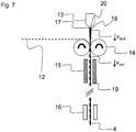
- a linear inductor according to the invention is preferably used for the treatment.
- the surface to be treated of the sheet-like composite is moved past, and this preferably at speeds of at least 50m / min but usually not more than 500m / min. Frequently, speeds in a range of 100 to 300m / min are achieved.
- any type of radiation suitable for softening the plastics is considered by the person skilled in the art.
- Preferred types of radiation are IR, UV, and microwaves.
- Preferred modes of vibration are ultrasound.
- IR rays which are also used for IR welding of sheet-like composites, wavelength ranges of 0.7 to 5 ⁇ m must be mentioned.
- laser beams in a wavelength range of 0.6 to less than 10.6 microns can be used.
- Short-wave radiators in the range of 1 to 1.6 ⁇ m are preferably halogen radiators.
- Medium-wave radiators in the range of> 1.6 to 3.5 microns for example, metal foil radiator.
- quartz emitters are often used. More and more often lasers are used.
- diode lasers are used in a wavelength range of 0.8 to 1 .mu.m
- Nd Y AG laser at about 1 .mu.m
- CO 2 laser at about 10.6 microns.
- high frequency techniques with a frequency range of 10 to 45 MHz, often in a power range of 0.1 to 100 kW are used.
- a hose can be formed by folding forms. This can, for example, on an in WO 2010/023859 in FIG. 3 done device described.
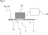
- Heating via contact with a solid may, for example, take place by means of a heating plate or heating mold which is in direct contact with the sheet-like composite and which transfers the heat to the sheet-like composite.
- Hot air may be directed onto the sheet composite by suitable fans, orifices or nozzles or a combination thereof. Frequently, contact heating and hot gas are used simultaneously.
- a hot gas flowed through and thereby heated and the Hot gas through suitable openings releasing holding device for a formed from the sheet-like composite jacket, the sheet-like composite by contact with the wall of the holding device and the hot gas to heat.
- the heating of the jacket can also take place in that the jacket is fixed with a jacket holder and the areas of the jacket to be heated are flown by one or two and more hot gas nozzles provided in the jacket holder.
- the above-described thermal treatment, the adhesive layer or the polymer inner layer is heated to a surface temperature in a range of 70 to 260 ° C, more preferably in a range of 80 to 220 ° C, to the orientation of the polymers in this layer or at least partially decrease in these two layers.
- the surface temperature is determined by the use of a LAND Cyclops TI35 + thermal imaging camera, scanning system with 8-sided polygon mirror, 25Hz at a measuring angle of 45 ° to the flat-lying sample (adjustable via photo tripod) at a distance of 240mm from the lens ring to the polymer inner layer and an emission factor 1 determined.
- the surface temperature is determined by hot air having a temperature in the range of 200 to 500 ° C and more preferably in a range of 250 to 400 ° C each over a treatment period in a range of 0.1 to 5 seconds, and more preferably in a range of 0 , Generated 5 to 3sec. This is particularly preferred for the treatment of hole areas.
- the maximum transmission intensity of at least one of the perforated cover layers containing an expanded polymer differ before and after the thermal treatment. This can usually be determined by different representations of the area considered by a polarization filter. Thus, the thermally treated areas differ from the adjoining thermally untreated areas on a surface by light-dark contrasts. The same applies to areas before and after the thermal treatment.
- the at least one hole covering layer is the polymer inner layer.
- the barrier layer is a metal foil or a metallized plastic layer.
- the thermally treated polymer layer usually the polymer inner layer of the later-shaped container, is provided over it in such a way that the barrier layer shines through.
- the change in the structure of the inner layer of the polymer resulting from the thermal treatment generally reveals a difference in gloss compared to the non-thermally treated layer.
- the areas of different gloss coincide with the thermally treated areas of the surface of the polymer inner layer.
- other areas of the sheet-like composite can also be thermally treated. These too show a different maximum transmission intensity compared to the untreated areas. This includes all areas in which a connection is done by sealing and / or creases are provided for folding. Under these areas, the longitudinal seams on which the sheet-like composite is formed into a tubular or shell-like structure are particularly preferred. Following the above thermal treatment, the thermally treated areas may be allowed to cool again.
- a sheet-like composite obtained by the above-described method for producing a sheet-like composite is provided, from which then in method step A2. by folding forms a container is formed.
- folds are understood to mean a process in which an elongate bend forming an angle is preferably produced in the folded planar composite by means of a folding edge of a folding tool.
- two adjacent surfaces of a sheet-like composite are often always more bent on each other.
- at least two adjoining folding surfaces are created, which are then joined at least in partial regions to form a container region.
- connection can be effected by any measure which appears suitable to the person skilled in the art and which makes possible a connection which is as gas- and liquid-tight as possible.
- the bonding can be done by sealing or gluing or a combination of both.
- sealing the connection is created by means of a liquid and its solidification.
- gluing chemical bonds are formed between the interfaces or surfaces of the two articles to be joined, creating the bond. It is often advantageous when sealing or gluing to press together the surfaces to be sealed or adhesive.
- the sealing temperature is preferably selected so that the plastic or resins involved in the sealing, preferably the polymers of the polymer outer layer and / or the inner layer of the polymer, are present as a melt.
- the sealing temperature should not be too high, so as not to put too much strain on the plastic or plastics, so that they do not lose their intended material properties.
- the sealing temperatures are at least 1 K, preferably at least 5 K and more preferably at least 10 K above the melting temperature of the respective plastic.
- a food can be enclosed by the sheet-like composite.
- Suitable foods are all foods known to the person skilled in the art for human consumption and also animal feed.
- Preferred foods are liquid above 5 ° C, for example drinks.
- Preferred foods are dairy products, soups, sauces, non-carbonated beverages such as fruit drinks and juices or teas.
- the foods can be used for a previously sterilized in previously sterilized container filled or enclosed with a likewise previously sterilized sheet-like composite.
- the food can be sterilized after filling or enclosing. This is done for example by autoclaving.
- foods especially fatty foods are preferred.
- fatty foods have a fat content in the dry matter of the fat of at least 10% by weight, preferably at least 30% by weight, preferably at least 40% by weight, more preferably at least 50% by weight, and most preferably at least 60 wt .-% on.
- a container with this fatty food is available, in which this can be stored very well for a long time uncorrupted.
- a tubular structure with a fixed longitudinal seam is formed from the sheet-like composite first by folding and sealing or gluing the overlapping butt edges.
- This tubular structure is laterally compressed, fixed and separated and formed into an open container by folding forms and sealing or gluing.
- the food can be filled already after fixing and before the separation and folding of the soil.
- a container obtained by folding forming the sheet-like composite, closed in the bottom area and opened in the head area is used.
- the molding of the sheet-like composite and the preservation of such an opened container can be carried out by any method of operation that appears suitable for the person skilled in the art.
- the molding can be done by, in their blank already taking into account the shape of the container, sheet-shaped container blanks so be folded, that over a jacket creates an open container. This is usually done in that after folding this container blank whose longitudinal edges sealed to form a side wall or glued and one side of the shell by folding and further fixing, in particular sealing or gluing, is closed.
- the filling with food can be done in several ways.
- the food and the container can be separated as far as possible before filling by suitable means such as treating the container with H 2 O 2 or UV radiation or other suitable high-energy radiation or plasma treatment or a combination of at least two thereof and heating the food be sterilized.
- This type of filling is often referred to as "aseptic filling" and is preferred according to the invention.
- the food-filled container is heated to reduce the germ count. This is preferably done by autoclaving. Less sterile items and containers can also be used in this procedure.
- the latter is no longer subjected to a treatment with a flame or a plasma.
- the maximum transmission intensity is determined by placing on a surface to be tested a polarizing filter film IFK-P-W76 from Schneider Optik GmbH. The film is rotated on the surface to be tested until the differences in the maximum transmission intensity can be seen with the maximum bright-dark contrast.
Description
Die vorliegende Erfindung betrifft allgemein einen einen Behälterinnenraum von der Umgebung abgrenzender Behälter, welcher zumindest teilweise aus einem flächenförmigen Verbund gebildet ist, wobei der flächenförmige Verbund als Verbundbestandteile mindestens beinhaltet:
- eine der Umgebung zugewandte Polymeraußenschicht;
- eine auf die Polymeraußenschicht zum Behälterinnenraum hin folgende Trägerschicht;
- eine auf die Trägerschicht zum Behälterinnenraum hin folgende Barriereschicht;
- eine auf die Barriereschicht zum Behälterinnenraum hin folgende Haftschicht;
- eine auf die Haftschicht um Behälterinnenraum hin folgende Polymerinnenschicht,
- an outer polymer facing layer;
- a carrier layer following the polymer outer layer towards the container interior;
- a following on the carrier layer to the container interior following barrier layer;
- a following on the barrier layer to the container interior adhesive layer;
- a polymer inner layer following the adhesive layer around the container interior,
Seit langer Zeit erfolgt die Konservierung von Nahrungsmitteln, seien es Nahrungsmittel für den menschlichen Verzehr oder auch Tiernahrungsprodukte, in dem diese entweder in einer Dose oder in einem mit einem Deckel verschlossenen Glas gelagert werden. Hierbei kann die Haltbarkeit beispielsweise dadurch erhöht werden, indem jeweils das Nahrungsmittel und der Behälter, hier Glas bzw. Dose, getrennt möglichst weitestgehend entkeimt werden und dann das Nahrungsmittel in den Behälter gefüllt und dieser verschlossen wird. Diese an sich über eine lange Zeit bewährte Maßnahme zur Erhöhung der Haltbarkeit von Nahrungsmitteln haben jedoch eine Reihe von Nachteilen, beispielsweise eine nochmals notwendige nachgelagerte Entkeimung.For a long time, the preservation of food, whether food for human consumption or animal food products by storing them in either a can or in a sealed glass with a lid. In this case, the durability can be increased, for example, by each of the food and the container, here glass or can, be sterilized as far as possible sterilized and then filled the food in the container and this is closed. However, this proven over a long time measure to increase the shelf life of food, however, have a number of disadvantages, such as a further necessary downstream sterilization.
Dosen und Gläser haben aufgrund ihrer im Wesentlichen zylindrischen Form den Nachteil, dass eine sehr dichte und platzsparende Lagerung nicht möglich ist. Zudem haben Dosen und Gläser ein erhebliches Eigengewicht, das zu einem erhöhten Energieaufwand beim Transport führt. Außerdem ist zur Herstellung von Glas, Weißblech oder Aluminium, selbst wenn die hierzu verwendeten Rohstoffe aus dem Recycling stammen, ein recht hoher Energieaufwand notwendig. Bei Gläsern kommt erschwerend ein erhöhter Transportaufwand hinzu, da diese meist in einer Glashütte vorgefertigt werden und dann unter Nutzen erheblicher Transportvolumina zu dem das Nahrungsmittel abfüllenden Betrieb transportiert werden müssen. Darüber hinaus lassen sich Gläser und Dosen nur mit einem erheblichen Kraftaufwand oder unter Zuhilfenahme von Werkzeugen und damit eher umständlich öffnen. Bei Dosen kommt eine hohe Verletzungsgefahr durch scharfe, beim Öffnen entstehende Kanten hinzu. Bei Gläsern kommt es immer wieder dazu, dass beim Füllen oder Öffnen der gefüllten Gläser Glassplitter in das Nahrungsmittel gelangen, die schlimmstenfalls zu inneren Verletzungen beim Verzehr des Nahrungsmittels führen können.Cans and glasses have the disadvantage due to their substantially cylindrical shape that a very dense and space-saving storage is not possible. In addition, cans and glasses have a considerable weight, which leads to increased energy consumption during transport. In addition, for the production of glass, tinplate or aluminum, even if the raw materials used for this purpose come from recycling, a fairly high energy consumption is necessary. For glasses comes added aggravating an increased transport costs, since these are usually prefabricated in a glassworks and then need to be transported using significant transport volumes to the food-filling operation. In addition, glasses and cans can be opened only with considerable effort or with the help of tools and thus rather cumbersome. With cans, there is a high risk of injury due to sharp edges created when opening. When it comes to glasses, it often happens that when filling or opening the filled glasses, glass fragments enter the food, which in the worst case can lead to internal injuries when eating the food.
Andere Verpackungssysteme sind aus dem Stand der Technik bekannt, um Nahrungsmittel über einen langen Zeitraum möglichst ohne Beeinträchtigungen zu lagern. Hierbei handelt es sich um aus flächenförmigen Verbunden - häufig auch als Laminat bezeichnet - hergestellte Behälter. Derartige flächenförmige Verbunde sind häufig aufgebaut aus einer thermoplastischen Kunststoffschicht, einer meist aus Karton oder Papier bestehenden Trägerschicht, einer Haftvermittlerschicht, einer Aluminiumschicht und einer weiteren Kunststoffschicht, wie unter anderem in
Diese Laminatbehälter weisen bereits viele Vorteile gegenüber den herkömmlichen Gläsern und Dosen auf. Gleichwohl bestehen Verbesserungsmöglichkeiten auch bei diesen Verpackungssystemen.These laminate containers already have many advantages over conventional glasses and cans. Nevertheless, there are also possibilities for improvement in these packaging systems.
So kommt es in Bereichen der flächenförmigen Verbunde, die bei der Herstellung des Behälters hohen mechanischen Belastungen ausgesetzt werden, immer wieder zur Bildung von kleinen Fehlstellen wie Rissen, Blasen, Delaminationsbereichen oder nicht gesiegelten Taschen bzw. Mikrokanälen bis hin zu Leckagen, in denen sich Keime einlagern oder in den Behälter eindringen können und das in dem Behälter befindliche Nahrungsmittel leichter verderben können. Diesen Keimen in kleinen Fehlstellen der Behälter kann auch durch ein stärkeres Entkeimen der Nahrungsmittel nicht begegnet werden. Sogar der Versuch eines stärkeren Entkeimens des Behälters vor dem Befüllen mit Nahrungsmittel führt kaum zu der gewünschten langen Haltbarkeit des Nahrungsmittels. Weiterhin führt jede Beschädigung einer Aluminiumbarriereschicht zu Störstellen im Hinblick auf Sauerstoffeintritt in den Behälter, der wiederum zu Qualitätseinbußen des Nahrungsmittels und damit zu einer verkürzten Haltbarkeit beiträgt. Besonders gefährdet sind Bereiche bei der Behälterherstellung, die Rillkreuze aufweisen, die besonders stark bzw. in mehrere Dimensionen gefaltet werden, beispielsweise in den Boden- und Kopfbereichsecken der Behälter.So it comes in areas of the sheet-like composites, which are exposed in the manufacture of the container high mechanical loads, again and again to the formation of small imperfections such as cracks, bubbles, Delaminationsbereichen or unsealed pockets or microchannels to leaks in which germs store or can penetrate into the container and spoil the food in the container easier. These germs in small imperfections of the container can not be met by a stronger sterilization of food. Even attempting to sterilize the container before filling it with food hardly results in the desired long shelf life of the food. Furthermore, any damage to an aluminum barrier layer leads to imperfections with regard to oxygen entry into the container, which in turn contributes to reduced quality of the food and thus to a shortened durability. Particularly at risk are areas in the container production, which have Rillkreuze that are particularly strong or folded into several dimensions, for example in the bottom and head area corners of the container.
Allgemein liegt die Aufgabe der vorliegenden Erfindung darin, die sich aus dem Stand der Technik ergebenden Nachteile zumindest teilweise zu beseitigen.In general, the object of the present invention is to at least partially overcome the disadvantages resulting from the prior art.
Zudem besteht eine erfindungsgemäße Aufgabe darin eine hohe Spannungsrisskorrosionsbeständigkeit bei zumindest gleich gutem Öffnungs- und Siegelverhalten sowie Sauerstoffundurchlässigkeit, insbesondere entlang der Siegelnähte, wie der Längsnaht, eines Behälters, bei geringem Materialeinsatz und einfacher Hochgeschwindigkeitsfertigung zu erhalten. Dieses gilt insbesondere dann, wenn Lebensmittel mit hohem Fettanteil, der oft als separiertes Fett wie Fettaugen vorliegt, lange Zeit bei Raumtemperatur oder gar höheren Temperaturen bei unterbrechen der Lager- und Kühlkette gelagert werden müssen. Im Zusammenhang mit dem Öffnungsverhalten soll insbesondere das Entstehen von Kunststofffäden vermieden werden. Derartige Fäden werden beispielsweise beim Öffnen von Perforationen beobachtet. Insbesondere bei flüssigkeitshaltigen Behälterfüllungen führt dieses häufig zu einem unerwünschten Anhaften der Flüssigkeiten an diesen Fäden, was zu einem unscharfen Ausgießen mit Nachlaufen führt. Außerdem können sich über die Öffnung stegartig spannende Fäden dazu führen, dass das Nahrungsmittel durch diese aufgestaut wird.In addition, an object of the invention is a high stress corrosion cracking resistance with at least as good opening and sealing behavior and oxygen impermeability, in particular along the sealing seams, as the longitudinal seam to receive a container, with low material usage and simple high-speed production. This is especially true when food with high fat content, which is often present as a separated fat such as grease eyes, long time at room temperature or even higher temperatures must be stored in interrupting the storage and cold chain. In connection with the opening behavior in particular the emergence of plastic threads should be avoided. Such threads are observed, for example, when opening perforations. In particular, in the case of liquid-containing container fillings, this often leads to an undesired adhesion of the liquids to these threads, which leads to a blurred pouring with run-on. In addition, over the opening web-like exciting threads can cause the food is dammed by this.
Einen Beitrag zur Lösung mindestens einer der eingangs genannten Aufgaben leisten die Gegenstände der kategoriebildenden Ansprüche. Die Gegenstände der von den kategoriebildenden Ansprüchen abhängigen Unteransprüche stellen bevorzugte Ausgestaltungen dieses Lösungsbeitrages dar.A contribution to the solution of at least one of the objects mentioned above is provided by the objects of the category-forming claims. The subject matters dependent on the categoriebildenden claims dependent claims represent preferred embodiments of this solution contribution.
Einen Beitrag zur Lösung der vorstehenden Aufgaben leistet ein einen Behälterinnenraum von der Umgebung abgrenzender Behälter, welcher zumindest teilweise aus einem flächenförmigen Verbund gebildet ist, wobei der flächenformige Verbund als Verbundbestandteile mindestens beinhaltet:
- eine der Umgebung zugewandte Polymeraußenschicht;
- eine auf die Polymeraußenschicht zum Behälterinnenraum hin folgende Trägerschicht;
- eine auf die Trägerschicht zum Behälterinnenraum hin folgende Barriereschicht;
- eine auf die Barriereschicht zum Behälterinnenraum hin folgende Haftschicht;
- eine auf die Haftschicht um Behälterinnenraum hin folgende Polymerinnenschicht;
- an outer polymer facing layer;
- a carrier layer following the polymer outer layer towards the container interior;
- a following on the carrier layer to the container interior following barrier layer;
- a following on the barrier layer to the container interior adhesive layer;
- a polymer inner layer following the adhesive layer around the container interior;
Die Formulierung "auf eine Schicht X zum Behälterinnenraum hin folgende weitere Schicht Y", wie sie vorstehend verwendet wird, soll ausdrücken, dass sich die Schicht Y näher am Innenraum befindet als die Schicht X. Diese Formulierung besagt nicht zwingend, dass die Schicht Y unmittelbar auf die Schicht X folgt sondern schließt vielmehr auch eine Konstellation ein, bei der sich zwischen der Schicht X und der Schicht Y eine oder mehrere weitere Schichten befinden. Gemäß einer besonderen Ausgestaltung ist jedoch der flächenförmige Verbund dadurch gekennzeichnet, dass zumindest die Trägerschicht unmittelbar auf die Polymeraußenschicht, die Haftschicht unmittelbar auf die Barriereschicht und die Polymerinnenschicht unmittelbar auf die Haftschicht folgt.The phrase "further layer Y following a layer X toward the interior of the container" as used above is intended to express that layer Y is closer to the interior than layer X. This formulation does not necessarily imply that layer Y is instantaneous rather follows the layer X but rather also includes a constellation in which there are one or more further layers between the layer X and the layer Y. According to a particular embodiment, however, the sheet-like composite is characterized in that at least the carrier layer directly on the polymer outer layer, the adhesive layer directly on the barrier layer and the polymer inner layer immediately following the adhesive layer.
Der erfindungsgemäße Behälter weist vorzugsweise mindestens eine, bevorzugt zwischen 6 und 16 Kanten, besonders bevorzugt zwischen 7 und 12 oder auch mehr Kanten auf. Als Kante werden erfindungsgemäß insbesondere Bereiche verstanden, die beim Falten einer Fläche durch das Übereinanderlegen von zwei Teilen dieser Fläche entstehen. Als beispielhafte Kanten seien die länglichen Berührungsbereiche von jeweils zwei Wandflächen eines im Wesentlichen quaderförmigen Behälters genannt. Ein solcher quaderförmiger Behälter hat in der Regel 12 Kanten. In dem Behälter stellen die Behälterwände vorzugsweise die von den Kanten eingerahmten Flächen des Behälters dar. Die Behälterwände eines erfindungsgemäßen Behälters sind vorzugsweise zu mindestens 50, bevorzugt zu mindestens 70 und darüber hinaus bevorzugt zu mindestens 90% ihrer Fläche aus einer Trägerschicht als Teil des flächenförmigen Verbunds ausgebildet.The container according to the invention preferably has at least one, preferably between 6 and 16 edges, more preferably between 7 and 12 or even more edges. According to the invention, edges are understood to be, in particular, regions which, when a surface is folded, result from the superposition of two parts of this surface. As exemplary edges are the elongated contact areas each called by two wall surfaces of a substantially cuboid container. Such a cuboid container usually has 12 edges. In the container, the container walls preferably represent the surfaces of the container framed by the edges. The container walls of a container according to the invention are preferably at least 50, preferably at least 70 and more preferably at least 90% of their area from a carrier layer as part of the sheet-like composite educated.
Als Polymeraußenschicht, welche üblicherweise eine Schichtdicke in einem Bereich von 5 bis 25 µm, besonders bevorzugt in einem Bereich von 8 bis 20 µm und am meisten bevorzugt in einem Bereich von 10 bis 18 µm aufweist, kommen insbesondere thermoplastische Kunststoffe in Betracht. In diesem Zusammenhang bevorzugte thermoplastische Kunststoffe sind insbesondere solche mit einer Schmelztemperatur in einem Bereich von 80 bis 155°C, vorzugsweise in einem Bereich von 90 bis 145°C und besonders bevorzugt in einem Bereich von 95 bis 135°C.As a polymer outer layer, which usually has a layer thickness in a range of 5 to 25 .mu.m, more preferably in a range of 8 to 20 microns and most preferably in a range of 10 to 18 microns, in particular thermoplastics come into consideration. Thermoplastics preferred in this context are in particular those having a melting temperature in a range from 80 to 155.degree. C., preferably in a range from 90 to 145.degree. C. and more preferably in a range from 95 to 135.degree.
Gegebenenfalls kann die Polymeraußenschicht neben dem thermoplastischen Polymer auch einen anorganischen Füllstoff beinhalten. Als anorganischer Füllstoff kommen alle dem Fachmann geeignet erscheinenden, vorzugsweise teilchenförmige Feststoffe in Betracht, die unter anderem zu einer verbesserter Wärmeverteilung in dem Kunststoff und damit zu einer besseren Siegelbarkeit des Kunststoffs führen. Vorzugsweise liegen die durch Siebanalyse bestimmten mittlere Teilchengrößen (d50%) der anorganischen Feststoffe in einem Bereich von 0,1 bis 10 µm, vorzugsweise in einem Bereich von 0,5 bis 5 µm und besonders bevorzugt in einem Bereich von 1 bis 3 µm. Als anorganische Feststoffe kommen vorzugsweise Metallsalze oder Oxide von zwei- bis vierwertigen Metallen in Betracht. Beispielsweise sind hier die Sulfate oder Carbonate des Calciums, Bariums oder Magnesiums oder Titandioxid, vorzugsweise Calciumcarbonat, zu nennen.Optionally, the polymer outer layer may also include an inorganic filler in addition to the thermoplastic polymer. Suitable inorganic fillers are all those which appear suitable to the person skilled in the art, preferably particulate solids, which, inter alia, lead to an improved heat distribution in the plastic and thus to a better sealability of the plastic. Preferably, the sieve analysis determined average particle sizes (d50%) of the inorganic solids in a range of 0.1 to 10 microns, preferably in a range of 0.5 to 5 microns and more preferably in a range of 1 to 3 microns. Suitable inorganic solids are preferably metal salts or oxides of di- to tetravalent metals. For example, the sulfates or carbonates of calcium, barium or magnesium or titanium dioxide, preferably calcium carbonate, may be mentioned here.
In diesem Zusammenhang ist es jedoch bevorzugt, dass die Polymeraußenschicht zu mindestens 60 Vol.-%, vorzugsweise mindestens 80 Vol.-% und besonders bevorzugt mindestens 95 Vol.-%, jeweils bezogen auf die Polymeraußenschicht, ein thermoplastisches Polymer beinhaltet.In this connection, however, it is preferred that the polymer outer layer contains at least 60% by volume, preferably at least 80% by volume and particularly preferably at least 95% by volume, in each case based on the outer polymer layer, of a thermoplastic polymer.
Als thermoplastische Polymere der Polymeraußenschicht eignen sich durch Kettenpolymerisation erhaltene Polymere, insbesondere Polyolefine, wobei cyclische Olefincopolymere (COC), polycyclische Olefin-copolymere (POC), insbesondere Polyethylen und Polypropylen, hierunter bevorzugt sind und Polyethylen besonders bevorzugt ist. Die mittels DIN 1133 (190°C/2,16kg) ermittelten Schmelzflussraten (melt flow rate - MFR) der auch als Mischungen von mindestens zwei einsetzbaren thermoplastischen Polymere liegt vorzugsweise in einem Bereich von 1 bis 25 g/10 min, vorzugsweise in einem Bereich von 2 bis 9 g/10 min und besonders bevorzugt in einem Bereich von 3,5 bis 8 g/10 min.Suitable thermoplastic polymers of the polymer outer layer are polymers obtained by chain polymerization, in particular polyolefins, cyclic olefin copolymers (COC), polycyclic olefin copolymers (POC), in particular polyethylene and polypropylene, being preferred here, and polyethylene being particularly preferred. The melt flow rate ( MFR), which is also determined as mixtures of at least two usable thermoplastic polymers by means of DIN 1133 (190 ° C./2.16 kg), is preferably in the range from 1 to 25 g / 10 min, preferably in one range from 2 to 9 g / 10 min, and more preferably in a range of from 3.5 to 8 g / 10 min.
Unter den Polyethlylenen sind HDPE, MDPE, LDPE, LLDPE und PE sowie Mischungen aus mindestens zwei davon für das erfindungsgemäße Verfahren bevorzugt. Die mittels DIN 1133 (190°C/2,16kg) ermittelten MFR dieser Polymere liegen vorzugsweise in einem Bereich von 3 bis 15 g/10 min, vorzugsweise in einem Bereich von 3 bis 9 g/10 min und besonders bevorzugt in einem Bereich von 3,5 bis 8 g/10 min. Im Zusammenhang mit der Polymeraußenschicht ist es bevorzugt Polyethylene mit einer Dichte (gemäß ISO 1183-1:2004) in einem Bereich von 0,900 bis 0,960 g/cm3 vorzugsweise in einem Bereich von 0,912 bis 0,950 g/cm3, einem MFR in einem Bereich von 2,5 bis 8 g/10min und einer Schmelztemperatur (gemäß ISO 11357) in einem Bereich von 96 bis 135°C einzusetzen.Among the polyethlylenes, HDPE, MDPE, LDPE, LLDPE and PE and mixtures of at least two thereof are preferred for the process of the present invention. The MFRs of these polymers determined by means of DIN 1133 (190 ° C./2.16 kg) are preferably in a range of 3 to 15 g / 10 min, preferably in a range of 3 to 9 g / 10 min and more preferably in a range of 3.5 to 8 g / 10 min. In the context of the polymer outer layer, it is preferable to have polyethylenes having a density (according to ISO 1183-1: 2004) in a range of 0.900 to 0.960 g / cm 3, preferably in a range of 0.912 to 0.950 g / cm 3 , an MFR in a range from 2.5 to 8 g / 10min and a melting temperature (according to ISO 11357) in a range of 96 to 135 ° C to use.
Gegebenenfalls kann/können auf der zur Umgebung bin zugwandten Seite der Polymeraußenschicht noch eine weitere Schicht bzw. weitere Schichten vorgesehen sein. Insbesondere kann auf der zur Umgebung bin zugewandten Seite der Polymeraußenschicht noch eine Druckschicht aufgetragen sein.Optionally, a further layer or further layers may be provided on the side of the outer polymer layer facing the surroundings be. In particular, a pressure layer can also be applied to the side of the polymer outer layer facing the surroundings.
Als auf die Polymeraußenschicht zum Behälterinnenraum hin folgende Trägerschicht kann jedes dem Fachmann für diesen Zweck geeignete Material eingesetzt werden, welches eine ausreichende Festigkeit und Steifigkeit aufweist, um den Behälter soweit Stabilität zu geben, dass der Behälter im gefüllten Zustand seine Form im Wesentlichen beibehält. Neben einer Reihe von Kunststoffen sind auf Pflanzen basierende Faserstoffe, insbesondere Zellstoffe, vorzugsweise verleimte, gebleichte und/oder ungebleichte Zellstoffe bevorzugt, wobei Papier und Karton besonders bevorzugt sind. Das Flächengewicht der Trägerschicht liegt vorzugsweise in einem Bereich von 140 bis 450 g/m2, besonders bevorzugt in einem Bereich von 160 bis 400 g/m2 und am meisten bevorzugt in einem Bereich von 170 bis 350 g/m2.Any backing material suitable for this purpose may be used as the backing layer following the polymer outer layer toward the interior of the container, which material has sufficient strength and rigidity to give stability to the container so that the container essentially retains its shape in the filled state. In addition to a number of plastics, plant-based pulps, in particular pulps, preferably glued, bleached and / or unbleached pulps are preferred, with paper and board being particularly preferred. The basis weight of the carrier layer is preferably in a range of 140 to 450 g / m 2 , more preferably in a range of 160 to 400 g / m 2, and most preferably in a range of 170 to 350 g / m 2 .
Als auf die Trägerschicht zum Behälterinnenraum hin folgende Barriereschicht kann jedes dem Fachmann für diesen Zweck geeignete Material eingesetzt werden, welches eine ausreichende Barrierewirkung insbesondere gegenüber Sauerstoff aufweist. Bei der Barriereschicht kann es sich um eine Metallfolie, wie etwa eine Aluminiumfolie, um eine metallisierte Folie oder aber um eine Kunststoffbarriereschicht handeln.As following the carrier layer to the container interior following barrier layer can be used any of the skilled person for this purpose suitable material which has a sufficient barrier effect especially against oxygen. The barrier layer may be a metal foil, such as an aluminum foil, a metallized foil or a plastic barrier layer.
Im Falle einer Kunststoffbarriereschicht beinhaltet diese vorzugsweise mindestens 70 Gew.-%, besonders bevorzugt mindestens 80 Gew.-% und am meisten bevorzugt mindestens 95 Gew.-% mindestens eines Kunststoffs, der dem Fachmann für diesen Zweck insbesondere wegen für Verpackungsbehälter geeigneter Aroma- bzw. Gasbarriereeigenschaften bekannt ist. Vorzugsweise werden hier thermoplastische Kunststoffe eingesetzt. In dem erfindungsgemäßen Behälter kann es sich als vorteilhaft erweisen, wenn die Kunststoffbarriereschicht eine Schmelztemperatur (gemäß ISO 11357) in einem Bereich von mehr als 155 bis 300°C, vorzugsweise in einem Bereich von 160 bis 280°C und besonders bevorzugt in einem Bereich von 170 bis 270°C besitzt. Als Kunststoffe, insbesondere thermoplastische Kunststoffe, kommen hier N oder O tragenden Kunststoffe sowohl für sich als auch in Mischungen aus zwei oder mehr in Betracht. Im Falle einer Kunststoffbarriereschicht ist es weiterhin bevorzugt, dass diese möglichst homogen ist und daher vorzugsweise aus Schmelzen, wie sie beispielsweise durch Extrusion, insbesondere Schichtextrusion, entstehen, erhalten werden kann. Hingegen sind Kunststoffbarriereschichten, die durch Abscheidung aus einer Lösung oder Dispersion von Kunststoffen erhältlich sind, weniger bevorzugt, da diese, insbesondere, wenn eine Abscheidung oder Bildung aus einer Kunststoffdispersion erfolgt, oft mindestens teilpartikuläre Strukturen aufweisen, die im Vergleich zu aus Schmelzen erhältlichen Kunststoffbarriereschichten weniger gute Gas- und Feuchtigkeitsbarriere-eigenschaften zeigen.In the case of a plastic barrier layer, this preferably comprises at least 70% by weight, particularly preferably at least 80% by weight and most preferably at least 95% by weight of at least one plastic which is suitable for this purpose by the person skilled in the art, in particular for flavoring or packaging containers Gas barrier properties is known. Preferably, thermoplastic materials are used here. In the container according to the invention, it may prove advantageous if the plastic barrier layer has a melting temperature (according to ISO 11357) in a range of more than 155 to 300 ° C, preferably in a range of 160 to 280 ° C, and more preferably in a range of 170 to 270 ° C has. As plastics, in particular thermoplastics, here N or O-bearing plastics come into consideration either alone or in mixtures of two or more. In the case of a plastic barrier layer, it is further preferred that this is as homogeneous as possible and therefore can preferably be obtained from melts, such as those produced by extrusion, in particular layer extrusion. On the other hand, plastic barrier layers obtainable by deposition from a solution or dispersion of plastics are less preferred since, especially when deposited or formed from a plastic dispersion, they often have at least partially particulate structures which are less as compared to plastic barrier layers obtainable from melts show good gas and moisture barrier properties.
Als geeignete Polymere, auf denen die Kunststoffbarriereschichten basieren können, kommen insbesondere Polyamid (PA) oder Polyethylenvinyl-alkohol (EVOH) oder einer Mischung daraus in Betracht.Suitable polymers on which the plastic barrier layers can be based are, in particular, polyamide (PA) or polyethylene-vinyl alcohol (EVOH) or a mixture thereof.
Als PA kommen alle dem Fachmann für die Herstellung von und dem Einsatz in den erfindungsgemäßen Behältern geeignet erscheinenden PAs in Betracht. Besonders sind hier PA 6, PA 6.6, PA 6.10, PA 6.12, PA 11 oder PA 12 oder eine Mischung aus mindestens zwei davon zu nennen, wobei PA 6 und PA 6.6 besonders bevorzugt sind und PA 6 ferner bevorzugt ist. PA 6 ist unter den Handelsnamen Akulon®, Durethan® und Ultramid® kommerziell erhältlich. Darüber hinaus geeignet sind amorphe Polyamide wie z.B. MXD6, Grivory® sowie Selar®.. Das Molekulargewicht des PA sollte vorzugsweise so ausgewählt werden, dass der gewählte Molekulargewichtsbereich zum einen eine gute Schichtextrusion bei der Herstellung des flächigen Verbunds für den Behälter ermöglicht und der flächige Verbund zum anderen ausreichend gute mechanische Eigenschaften, wie eine hohe Bruchdehnung, eine hohe Abriebfestigkeit und eine ausreichende Steifigkeit für den Behälter selbst besitzt. Hieraus ergeben sich bevorzugte als Gewichtsmittel über Gelpermeationschromatographie (GPC) (gemäß ISO/DIS 16014-3:2003) mit Lichtstreuung (gemäß ISO/DIS 16014-5:2003) bestimmte Molekulargewichte in einem Bereich von 3x10³ bis 1x10⁷ g/mol, vorzugsweise in einem Bereich von 5x10³ bis 1x10⁶ g/mol und besonders bevorzugt in einem Bereich von 6x10³ bis 1x10⁵ g/mol. Zudem ist es im Zusammenhang mit den Verarbeitungs- und mechanischen Eigenschaften bevorzugt, dass das PA eine Dichte (gemäß ISO 1183-1:2004) in einem Bereich von 1,01 bis 1,40 g/cm3, vorzugsweise in einem Bereich von 1,05 bis 1,3 g/cm3 und besonders bevorzugt in einem Bereich von 1,08 bis 1,25 g/cm3 aufweist. Weiterhin ist es bevorzugt, dass das PA eine Viskositätszahl in einem Bereich von 130 bis 185 ml/g und vorzugsweise in einem Bereich von 140 bis 180, bestimmt nach ISO 307 in 95% Schwefelsäure, hat.Suitable PAs are all PAs which appear suitable to the person skilled in the art for the production of and use in the containers according to the invention. Particular mention may be made here of
Als EVOH können alle Polymere eingesetzt werden, welche dem Durchschnittsfachmann als für die Herstellung und Verwendung eines erfindungsgemäßen Behälters geeignet erscheinen. Beispiele geeigneter EVOHs sind unter anderem unter den Handelsnamen EVAL™ der EVAL Europe NV, Belgien in einer Vielzahl unterschiedlicher Ausführungen kommerziell erhältlich. Besonders geeignet erscheinen die Sorten EVAL™ F104B, EVAL™ LR101B oder EVAL™ LR171B.As EVOH, it is possible to use all polymers which appear to the person skilled in the art as suitable for the preparation and use of a container according to the invention. Examples of suitable EVOHs are commercially available under the trade names EVAL ™ from EVAL Europe NV, Belgium in a variety of different designs. Especially suitable are the grades EVAL ™ F104B, EVAL ™ LR101B or EVAL ™ LR171B.
Geeignete EVOH Sorten zeichnen sich durch mindestens eine, besonders bevorzugt durch alle der folgenden Eigenschaften aus:
- ein Ethylengehalt in
einem Bereich von 20 bis 60 mol %, bevorzugt 25 bis 45 mol% - eine Dichte (gemäß ISO 1183-1:2004) in
einem Bereich von 1,0bis 1,4 g/cm3,bevorzugt zwischen bis 1,3 g/cm3. - einen Schmelzpunkt (gemäß ISO11357) in einem Bereich von 115 bis 235°C, bevorzugt zwischen 165 bis 225°C
- ein MFR-Wert (gemäß ISO 1133: 210°C/2,16kg bei einer Schmelztemperatur des EVOH kleiner 230°C und 230°C/2,16kg bei einer Schmelztemperatur des EVOH in einem Bereich zwischen 210 bis 230°C) in
einem Bereich von 1 bis 20 g/10min,bevorzugt 2 bis 15 g/10min - eine Sauerstoffpermeationsrate (gemäß ISO 14663-2 Anhang C bei 20°C und 65% relativer Luftfeuchte) in einem Bereich von 0,05
bis bevorzugt zwischen 0,1bis 0,6 cm3×20µm/m2×Tag×atm.
- an ethylene content in a range of 20 to 60 mol%, preferably 25 to 45 mol%
- a density (according to ISO 1183-1: 2004) in a range of 1.0 to 1.4 g / cm 3 , preferably between 1.1 to 1.3 g / cm 3 .
- a melting point (according to ISO 11357) in a range of 115 to 235 ° C, preferably between 165 to 225 ° C
- an MFR value (according to ISO 1133: 210 ° C / 2.16kg at a melting temperature of the EVOH lower than 230 ° C and 230 ° C / 2.16kg at a melting temperature of the EVOH in a range between 210 to 230 ° C) in one Range of 1 to 20 g / 10min, preferably 2 to 15 g / 10min
- an oxygen permeation rate (according to ISO 14663-2 Annex C at 20 ° C and 65% relative humidity) in a range of 0.05 to 3.2 cm 3 x 20 μm / m 2 x day x atm, preferably between 0.1 to 0 , 6 cm 3 × 20 μm / m 2 × day × atm.
Im Falle eines Einsatzes von Polyamid als Kunststoffbarriereschicht ist es bevorzugt, dass die Polyamidschicht ein Flächengewicht in einem Bereich von 2 bis 120 g/m2, vorzugsweise in einem Bereich von 3 bis 75 g/m2 und besonders bevorzugt in einem Bereich von 5 bis 55 g/m2 besitzt. Weiterhin ist es in diesem Zusammenhang bevorzugt, dass die Kunststoffbarriereschicht eine Dicke in einem Bereich von 2 bis 90 µm, vorzugsweise ein Bereich von 3 bis 68 µm und besonders bevorzugt in einem Bereich von 4 bis 50 µm hat.In the case of using polyamide as a plastic barrier layer, it is preferable that the polyamide layer has a basis weight in a range of 2 to 120 g / m 2 , preferably in a range of 3 to 75 g / m 2 and more preferably in a range of 5 to 55 g / m 2. Furthermore, in this context, it is preferable that the plastic barrier layer has a thickness in a range of 2 to 90 μm, preferably in a range of 3 to 68 μm, and more preferably in a range of 4 to 50 μm.
Ferner gilt, dass im Falle von EVOH als Kunststoffbarriereschicht mindestens einer, vorzugsweise mindestens alle der zuvor für Polyamid aufgeführten Parameter hinsichtlich des Flächengewichtes und der Schichtdicke erfüllt sind.Furthermore, in the case of EVOH as a plastic barrier layer, at least one, preferably at least all of the parameters previously listed for polyamide are fulfilled with regard to the basis weight and the layer thickness.
Erfindungsgemäß bevorzugt als Barriereschicht ist jedoch der Einsatz einer Aluminiumfolie, welche vorteilhafterweise eine Dicke in einem Bereich von 3,5 bis 20 µm, besonders bevorzugt in einem Bereich von 4 bis 12 µm und ganz besonders bevorzugt in einem Bereich von 5 bis 9 µm aufweist.According to the invention, however, preferred as a barrier layer is the use of an aluminum foil, which advantageously has a thickness in a range from 3.5 to 20 .mu.m, more preferably in a range from 4 to 12 .mu.m and most preferably in a range from 5 to 9 .mu.m.
Wird eine Aluminiumfolie als Barriereschicht eingesetzt, so ist es erfindungsgemäß weiterhin bevorzugt, wenn die Aluminiumfolie über eine Laminierungsschicht an die Trägerschicht gebunden ist. In diesem Fall ist also zwischen der Barriereschicht und der Trägerschicht mit der Laminierungsschicht eine weitere Schicht vorgesehen.If an aluminum foil is used as the barrier layer, it is furthermore preferred according to the invention if the aluminum foil is bonded to the carrier layer via a laminating layer. In this case, so between the Barrier layer and the carrier layer with the lamination layer another layer provided.
Als Laminierungsschicht, welche üblicherweise eine Schichtdicke in einem Bereich von 8 bis 50 µm, besonders bevorzugt in einem Bereich von 10 bis 40 film und am meisten bevorzugt in einem Bereich von 15 bis 30 µm aufweist, kommen ebenso wie bei der Polymeraußenschicht insbesondere thermoplastische Kunststoffe in Betracht. In diesem Zusammenhang bevorzugte thermoplastische Kunststoffe sind wiederum solche mit einer Schmelztemperatur in einem Bereich von 80 bis 155°C, vorzugsweise in einem Bereich von 90 bis 145°C und besonders bevorzugt in einem Bereich von 95 bis 135°C. Geeignete thermoplastische Polymere für die Laminierungsschicht sind insbesondere Polyethylen oder Polypropylen, wobei der Einsatz von Polyethylen besonders bevorzugt ist. Auch hier kann als Polyethylen HDPE, MDPE, LDPE, LLDPE, PE oder eine Mischung aus mindestens zwei davon eingesetzt werden. Die mittels DIN 1133 ermittelten MFR der für die Laminierungsschicht einsetzbaren Polymere liegen vorzugsweise in einem Bereich von 3 bis 15 g/10 min, vorzugsweise in einem Bereich von 3 bis 9 g/10 min und besonders bevorzugt in einem Bereich von 3,5 bis 8 g/10 min. Im Zusammenhang mit der Laminierungsschicht ist es bevorzugt mit einer Dichte (gemäß ISO 1183-1:2004) in einem Bereich von 0,900 bis 0.960 g/cm3 vorzugsweise in einem Bereich von 0,912 bis 0,950 g/cm3, einem MFR in einem Bereich von 2,5 bis 8 g/10 min und einer Schmelztemperatur (gemäß ISO 11357)in einem Bereich von 96 bis 135°C einzusetzen.As a lamination layer, which usually has a layer thickness in a range of 8 to 50 microns, more preferably in a range of 10 to 40 film and most preferably in a range of 15 to 30 microns, come as well as the polymer outer layer in particular thermoplastic materials consideration. In this context, preferred thermoplastics are again those having a melting temperature in a range of 80 to 155 ° C, preferably in a range of 90 to 145 ° C and more preferably in a range of 95 to 135 ° C. Suitable thermoplastic polymers for the lamination layer are in particular polyethylene or polypropylene, wherein the use of polyethylene is particularly preferred. Here, too, can be used as polyethylene HDPE, MDPE, LDPE, LLDPE, PE or a mixture of at least two thereof. The MFR of the polymers usable for the lamination layer determined by means of DIN 1133 are preferably in a range of 3 to 15 g / 10 min, preferably in a range of 3 to 9 g / 10 min and more preferably in a range of 3.5 to 8 g / 10 min. In the context of the lamination layer, it is preferred to have a density (according to ISO 1183-1: 2004) in a range of 0.900 to 0.960 g / cm 3, preferably in a range of 0.912 to 0.950 g / cm 3 , an MFR in a range of 2.5 to 8 g / 10 min and a melting temperature (according to ISO 11357) in a range of 96 to 135 ° C to use.
Weiterhin kann im Falle einer Aluminiumfolie als Barriereschicht und dem Einsatz der vorstehend beschriebenen Laminierungsschicht zwischen der Barriereschicht und der Trägerschicht auch eine Haftvermittlerschicht zwischen der Aluminiumfolie und der Laminierungsschicht, zwischen der Laminierungsschicht und der Trägerschicht oder zwischen der Laminierungsschicht und der Barriereschicht und der Laminierungsschicht und der Trägerschicht vorgesehen sein.Furthermore, in the case of an aluminum foil as the barrier layer and the use of the above-described lamination layer between the barrier layer and the support layer, an adhesion promoter layer may also be interposed between the aluminum foil and the lamination layer, between the lamination layer and the support layer or between the lamination layer and the barrier layer and the lamination layer and the support layer be provided.
Als Haftvermittler kommen alle Polymere in Betracht, die mittels geeigneter funktioneller Gruppen in der Lage sind, durch das Ausbilden von lonenbindungen oder kovalenten Bindungen zu der Oberfläche der jeweils anderen Schicht eine feste Verbindung zu erzeugen. Vorzugsweise handelt es sich um funktionalisierte Polyolefine, die durch Co-Polymerisation von Ethylen mit Acrylsäuren wie Acrylsäure, Methacrylsäure, Crotonsäure, Acrylaten, Acrylatderivaten oder Doppelbindungen tragenden Carbonsäureanhydriden, beispielsweise Maleinsäureanhydrid, oder mindestens zwei davon, erhalten wurden. Hierunter sind Polyethylenmaleinsäureanhydrid-Pfropfpolymere besonders bevorzugt, die beispielsweise unter der Handelsbezeichnung Bynel® durch DuPont vertrieben werden.Adhesion promoters are all polymers which, by means of suitable functional groups, are capable of producing a solid compound by forming ionic bonds or covalent bonds to the surface of the respective other layer. Preference is given to functionalized polyolefins obtained by co-polymerization of ethylene with acrylic acids such as acrylic acid, methacrylic acid, crotonic acid, acrylates, acrylate derivatives or double bond-bearing carboxylic acid anhydrides, for example maleic anhydride, or at least two thereof. Among Polyethylenmaleinsäureanhydrid graft polymers are particularly preferred, which are marketed under the trade name Bynel ® by DuPont.
Gemäß einer besonderes Ausgestaltung des erfindungsgemäßen Behälters ist allerdings weder zwischen der vorzugsweise auf Polyethylen basierenden Laminierungsschicht und der Aluminiumfolie noch zwischen der vorzugsweise auf Polyethylen basierenden Laminierungsschicht und der Trägerschicht, vorzugsweise der Kartonschicht, eine Haftvermittlerschicht vorgesehen.According to a particular embodiment of the container according to the invention, however, neither between the preferably polyethylene-based lamination layer and the aluminum foil nor between the preferably polyethylene-based lamination layer and the carrier layer, preferably the paperboard layer, an adhesion promoter layer is provided.
Die auf die Barriereschicht zum Behälterinnenraum hin folgende Haftschicht basiert ebenso wie die vorstehend beschriebene Haftvermittlerschicht vorzugsweise auf Polymeren, die mittels geeigneter funktioneller Gruppen in der Lage sind durch das Ausbilden von Ionenbindungen oder kovalenten Bindungen zu der Oberfläche der jeweils anderen Schicht, insbesondere zu der Oberfläche der Aluminiumfolie, eine feste Verbindung, besonders bevorzugt eine chemische Bindung zu erzeugen. Vorzugsweise handelt es sich um funktionalisierte Polyolefine, die durch Co-Polymerisation von Ethylen mit Acrylsäure, Acrylaten, Acrylatderivaten oder Doppelbindungen tragenden Carbonsäureanhydriden, beispielsweise Maleinsäureanhydrid, oder mindestens zwei davon, erhalten wurden. Hierunter sind Polyethylenmaleinsäureanhydrid-Pfropfpolymere und Ethylen-Acrylsäure-Copolymere besonders bevorzugt, wobei Ethylen-Acrylsäure-Copolymere ganz besonders bevorzugt sind. Derartige Copolymere werden beispielsweise unter der Handelsbezeichnung Nucrel® durch DuPont oder unter der Handelsbezeichnung Escor® von ExxonMobile Chemicals vertrieben.The adhesive layer following the barrier layer towards the container interior, like the adhesion promoter layer described above, is preferably based on polymers which are capable, by means of suitable functional groups, of forming ionic bonds or covalent bonds to the surface of the respective other layer, in particular to the surface of the Aluminum foil, a solid compound, particularly preferably to produce a chemical bond. Preference is given to functionalized polyolefins obtained by co-polymerization of ethylene with acrylic acid, acrylates, acrylate derivatives or double bond-bearing carboxylic acid anhydrides, for example maleic anhydride, or at least two thereof. Of these, polyethylene maleic anhydride graft polymers and ethylene-acrylic acid copolymers are particularly preferred, with ethylene-acrylic acid copolymers completely are particularly preferred. Such copolymers are sold for example under the trade name Nucrel ® by DuPont or under the trade name Escor ® from ExxonMobil Chemicals.
Die auf die Haftschicht zum Behälterinnenraum hin folgende Polymerinnenschicht basiert ebenso wie die eingangs beschriebene Polymeraußenschicht auf thermoplastischen Polymeren, wobei die Polymerinnenschicht ebenso wie die Polymeraußenschicht einen teilchenförmigen anorganischen Feststoff beinhalten kann. Bevorzugt ist es jedoch, dass die Polymerinnenschicht zu mindestens 70 Gew.-%, vorzugsweise mindestens 80 Gew.-% und besonders bevorzugt mindestens 95 Gew.-%, jeweils bezogen auf die Polymerinnenschicht, ein thermoplastisches Polymer beinhaltet.The polymer inner layer following the adhesive layer towards the container interior, like the polymer outer layer described above, is based on thermoplastic polymers, wherein the polymer inner layer as well as the polymer outer layer may include a particulate inorganic solid. However, it is preferred that the polymer inner layer contains at least 70 wt .-%, preferably at least 80 wt .-% and particularly preferably at least 95 wt .-%, each based on the inner polymer layer, a thermoplastic polymer.
In diesem Zusammenhang besonders bevorzugt ist es, dass die Polymerinnenschicht mindestens 70 Gew.-%, besonders bevorzugt mindestens 75 Gew.-% und am meisten bevorzugt mindestens 80 Gew.-%, jeweils bezogen auf die Polymerinnenschicht, eines mittels eines Metallocen-Katalysators hergestellten Polyolefins, vorzugsweise eines mittels eines Metallocen-Katalysators hergestellten Polyethylens (mPE), beinhaltet.In this context, it is particularly preferred that the polymer inner layer at least 70 wt .-%, more preferably at least 75 wt .-% and most preferably at least 80 wt .-%, each based on the inner polymer layer, one prepared by means of a metallocene catalyst Polyolefins, preferably a produced by a metallocene catalyst polyethylene (mPE) includes.
Erfindungsgemäß besonders bevorzugt ist es, dass die Polymerinnenschicht eine Mischung aus einem mittels eines Metallocen-Katalysators hergestelltem Polyolefin und einem weiteren Mischungspolymer ist, wobei es sich bei dem weiteren Mischungspolymer vorzugsweise um nicht mittels eines Metallocen-Katalysators hergestelltes Polyethylen, vorzugsweise um nicht mittels eines Metallocen-Katalysators hergestelltes LDPE handelt. Vorzugsweise handelt es sich bei der Polymerinnenschicht um eine Mischung aus 70 bis 95 Gew.-%, besonders bevorzugt 75 bis 85 Gew.-% mPE und 5 bis 30 Gew.-%, besonders bevorzugt 15 bis 25 Gew.-% LDPE.According to the invention, it is particularly preferred that the polymer inner layer is a mixture of a polyolefin prepared by a metallocene catalyst and another mixture polymer, wherein the further mixture polymer is preferably polyethylene not prepared by means of a metallocene catalyst, preferably not by means of a metallocene Catalyst produced LDPE is. Preferably, the polymer inner layer is a mixture of 70 to 95 wt .-%, particularly preferably 75 to 85 wt .-% mPE and 5 to 30 wt .-%, particularly preferably 15 to 25 wt .-% LDPE.
Vorzugsweise weist das Polymer bzw. die Polymermischung der Polymerinnenschicht eine Dichte (gemäß ISO 1183-1:2004) in einem Bereich von 0,900 bis 0,930 g/ cm3, besonders bevorzugt in einem Bereich von 0,900 bis 0,920 g/ cm3 und am meisten bevorzugt in einem Bereich von 0,900 bis 0,910 g/cm3 auf, während der MFR (ISO 1133, 190°C/2,16kg) vorzugsweise in einem Bereich von 4 bis 17 g/10min, besonders bevorzugt in einem Bereich von 4,5 bis 14 g/10min und am meisten bevorzugt in einem Bereich von 5 bis 10 g/10 min liegt.Preferably, the polymer or polymer mixture of the inner polymer layer has a density (according to ISO 1183-1: 2004) in a range of 0.900 to 0.930 g / cm 3 , more preferably in a range of 0.900 to 0.920 g / cm 3, and most preferably in a range of 0.900 to 0.910 g / cm 3 , while the MFR (ISO 1133, 190 ° C / 2.16kg) is preferably in a range of 4 to 17 g / 10min, more preferably in a range of 4.5 to 14 g / 10 min, and most preferably in a range of 5 to 10 g / 10 min.
Gemäß einer besonders bevorzugten Ausgestaltung des erfindungsgemäßen Behälters folgt die Polymerinnenschicht unmittelbar auf die Haftschicht. Zwischen der vorzugsweise mPE beinhaltenden Polymerinnenschicht und der Haftschicht ist demnach keine weitere Schicht, insbesondere keine weitere auf Polyethylen basierende Schicht, ganz besonders bevorzugt keine weitere LDPE- oder HDPE-Schicht vorgesehen.According to a particularly preferred embodiment of the container according to the invention, the polymer inner layer directly follows the adhesive layer. Accordingly, no further layer, in particular no further polyethylene-based layer, very particularly preferably no further LDPE or HDPE layer is provided between the preferably mPE-containing polymer inner layer and the adhesive layer.
Der erfindungsgemäße Behälter ist nun dadurch gekennzeichnet, dass die Schichtdicke der Haftschicht SDHS größer ist als die Schichtdicke der Polymerinnenschicht SDPIS. Besonders bevorzugt ist es dabei, dass die Schichtdicke der Haftschicht SDHS um einen Faktor in einem Bereich von 1,1 bis 5, noch mehr bevorzugt in einem Bereich von 1,2 bis 4 und am meisten bevorzugt in einem Bereich von 1,3 bis 3,5 größer ist als die Schichtdicke der Polymerinnenschicht SDPIS.The container according to the invention is now characterized in that the layer thickness of the adhesive layer SD HS is greater than the layer thickness of the polymer inner layer SD PIS . It is particularly preferred that the layer thickness of the adhesive layer SD HS by a factor in a range of 1.1 to 5, more preferably in a range of 1.2 to 4 and most preferably in a range of 1.3 to 3.5 is greater than the layer thickness of the polymer inner layer SD PIS .
Die Gesamtdicke der Haftschicht und der Polymerinnenschicht liegt häufig im Bereich von 10 bis 120 µm, vorzugsweise in einem Bereich von 15 bis 80 µm und besonders bevorzugt in einem Bereich von 18 bis 60 µm. Die bevorzugten Schichtdicken der einzelnen beiden Schichten ergeben sich aus den obenstehenden Faktoren.The total thickness of the adhesive layer and the polymer inner layer is often in the range of 10 to 120 microns, preferably in a range of 15 to 80 microns and more preferably in a range of 18 to 60 microns. The preferred layer thicknesses of the individual two layers result from the above factors.
Weiterhin entspricht es einer besonderen Ausgestaltung des erfindungsgemäßen Behälters, dass mindestens die Polymerinnenschicht oder mindestens die Haftschicht oder mindestens beide dieser Schichten ein durch Strecken orientiertes Polymer, vorzugsweise ein durch monoaxiales Verstrecken orientiertes Polymer beinhalten. Derartige Schichten sind beispielsweise dadurch erhältlich, dass die nach Extrusion aufgetragenen Schichten, in denen das thermoplastische Polymer noch oberhalb des Schmelzpunktes erwärmt ist, in monoaxialer Richtung gestreckt und dann zum Zwecke der Thermofixiernng im gestreckten Zustand auf eine Temperatur unterhalb des Schmelzpunktes abgekühlt wird, um so die Orientierung der Polymerketten zu fixieren.Furthermore, it corresponds to a particular embodiment of the container according to the invention that at least the inner polymer layer or at least the adhesive layer or at least both of these layers include a stretch-oriented polymer, preferably a monoaxially oriented polymer oriented. Such layers are obtainable, for example, by stretching the layers applied after extrusion, in which the thermoplastic polymer is still heated above the melting point, in the uniaxial direction and then cooling them in the stretched state to a temperature below the melting point for the purpose of heat setting to fix the orientation of the polymer chains.
Um die Öffenbarkeit des erfindungsgemäßen Behälters zu erleichtern, weist die Trägerschicht mindestens ein Loch auf, das mindestens mit der Barriereschicht, der Haftschicht und der Polymerinnenschicht als Lochdeckschichten überdeckt ist.In order to facilitate the Öffenbarkeit of the container according to the invention, the support layer has at least one hole which is covered at least with the barrier layer, the adhesive layer and the polymer inner layer as Lochdeckschichten.
Gemäß dem erfindungsgemäßen Behälter weist die Trägerschicht ein Loch auf, das mindestens mit der Polymeraußenschicht, der Barriereschicht, der Haftschicht und der Polymerinnenschicht als Lochdeckschichten überdeckt ist. Eine solche Ausgestaltung eines Verbundes ist beispielsweise in der
Im Zusammenhang mit dieser ersten besonderen Ausgestaltung des erfindungsgemäßen Behälters kann das in der Trägerschicht vorgesehene Loch jede dem Fachmann bekannte und für verschieden Verschlüsse oder Trinkhalme geeignete Form haben. Häufig weist das Loch in der Aufsicht Rundungen auf. So kann das Loch im Wesentlichen kreisrund, oval, ellipsen- oder tropfenförmig sein. Mit der Form des Lochs in der Trägerschicht wird meist auch die Form der Öffnung, die entweder durch einen mit dem Behälter verbundenen offenbaren Verschluss, durch den der Behälterinhalt nach dem Öffnen aus dem Behälter entfernt wird, oder durch einen Trinkhalm in dem Behälter erzeugt wird, vorbestimmt. Damit haben die Öffnungen des geöffneten Behälters häufig Formen, die mit dem Loch in der Trägerschicht vergleichbar oder sogar gleich sind.In connection with this first particular embodiment of the container according to the invention, the hole provided in the carrier layer can have any shape known to the person skilled in the art and suitable for different closures or drinking straws. Often, the hole in the supervision curves on. Thus, the hole may be substantially circular, oval, elliptical or teardrop-shaped. With the shape of the hole in the carrier layer is usually the shape of the opening, the either predetermined by an openable closure associated with the container, whereby the container contents are removed from the container after opening, or produced by a drinking straw in the container. Thus, the openings of the opened container often have shapes that are comparable or even equal to the hole in the carrier layer.
Im Zusammenhang mit dem Überdecken des Lochs der Trägerschicht ist es im Zusammenhang mit der ersten besonderen Ausgestaltung des erfindungsgemäßen Behälters bevorzugt, dass die Lochdeckschichten mindestens teilweise, vorzugsweise zu mindestens 30%, bevorzugt mindestens 70% und besonders bevorzugt zu mindestens 90% der durch das Loch gebildeten Fläche miteinander verbunden sind. Bevorzugt ist ferner, dass die Lochdeckschichten in dem Bereich der das Loch umschließenden Lochkanten miteinander verbunden sind und vorzugsweise verbunden an der Lochkante anliegen, um so über eine sich über die gesamte Lochfläche erstreckende Verbindung eine verbesserte Dichtigkeit zu erzielen. Häufig sind die Lochdeckschichten über den durch das Loch in der Trägerschicht gebildeten Bereich miteinander verbunden. Dieses führt zu einer guten Dichtigkeit des aus dem Verbund gebildeten Behälters und damit zu der gewünschten hohen Haltbarkeit der in dem Behälter aufbewahrten Lebensmittel.In connection with the covering of the hole of the carrier layer, it is preferred in connection with the first particular embodiment of the container according to the invention that the perforated cover layers are at least partially, preferably at least 30%, preferably at least 70% and particularly preferably at least 90% through the hole formed surface are interconnected. It is further preferred that the perforated cover layers are connected to each other in the region of the hole edges enclosing the hole and preferably abut against the hole edge in order to achieve improved tightness over a connection extending over the entire hole surface. Frequently, the hole-covering layers are connected to each other via the region formed by the hole in the carrier layer. This leads to a good tightness of the container formed from the composite and thus to the desired high durability of stored in the container food.
Meist wird die Öffnung des Behälters durch mindestens teilweises Zerstören der das Loch überdeckenden Lochdeckschichten erzeugt. Dieses Zerstören kann durch Schneiden, Eindrücken in den Behälter oder Herausziehen aus dem Behälter erfolgen. Das Zerstören kann durch ein mit dem Behälter verbundenen und im Bereich des Lochs, meist oberhalb des Lochs angeordneten, öffnenbaren Verschluss oder einen Trinkhalm, der durch die das Loch bedeckenden Lochdeckschichten gestoßen wird, erfolgen.Mostly, the opening of the container is created by at least partially destroying the hole covering layers covering the hole. This destruction can be done by cutting, pushing into the container or pulling out of the container. Destroying can take place by means of a receptacle which is connected to the container and arranged in the region of the hole, usually above the hole, or a drinking straw which is pushed through the perforated covering layers covering the hole.
Gemäß einer zweiten besonderen Ausgestaltung des erfindungsgemäßen Behälters ist es bevorzugt, dass die Trägerschicht eine Vielzahl von Löchern in Form einer Perforation aufweist, wobei die einzelnen Löcher mindestens mit der Barriereschicht, der Haftschicht und der Polymerinnenschicht als Lochdeckschichten überdeckt sind. Der Behälter kann dann durch Aufreißen entlang der Perforation geöffnet werden. Grundsätzlich können die Löcher in der Trägerschicht, die vorzugsweise auch alle über der Trägerschicht in Richtung der Umgebung liegenden Schichten (Polymeraußenschicht und gegebenenfalls Druckschicht) erstrecken, jede dem Fachmann zur Ausgestaltung eines zu öffnenden Bereichs in dem erfindungsgemäßen Behälter geeignet erscheinende Form aufweisen. Bevorzugt sind jedoch in der Aufsicht kreisförmige oder längliche Löcher, die vorzugsweise entlang einer Linie verlaufen, die eine Perforation in einer Behälterwand des erfindungsgemäßen Behälters ausbildet. Derartige Perforationen werden bevorzugt mittels eines Lasers erzeugt, der die vormals in dem Loch befindlichen Schichten entfernt. Es ist ferner möglich, dass die Perforation insgesamt als eine linienförmige Schwächung des flächenförmigen Verbunds ausgebildet ist, die im Bereich der Schwächung Gruppen von Abschnitten mit einer im Vergleich zu der Schwächung geringeren Schichtdicke aufweist. Diese Perforationen werden bevorzugt durch mechanische, meist Klingen aufweisende, Perforationswerkzeuge erhalten. Insbesondere wird hierdurch erreicht, dass sich der erfindungsgemäße Behälter ohne übermäßigen Kraftaufwand oder gar der Zuhilfenahme eines Werkzeugs bei geringerer Verletzungsgefahr öffnen lassen kann, in dem die Behälterwand des erfindungsgemäßen Behälters entlang der so gebildeten Perforation aufgerissen wird.According to a second particular embodiment of the container according to the invention, it is preferred that the carrier layer has a plurality of holes in the form of a Having perforation, wherein the individual holes are covered at least with the barrier layer, the adhesive layer and the inner polymer layer as Lochdeckschichten. The container can then be opened by tearing along the perforation. In principle, the holes in the carrier layer, which preferably also extend over the carrier layer in the direction of the environment lying layers (polymer outer layer and optionally printing layer), each have the skilled person for the design of an openable area in the container according to the invention seem appropriate form. However, in plan view, circular or oblong holes, which preferably extend along a line which forms a perforation in a container wall of the container according to the invention, are preferred. Such perforations are preferably produced by means of a laser which removes the layers previously located in the hole. It is also possible that the perforation as a whole is formed as a linear weakening of the sheet-like composite, which has groups of sections in the region of the weakening with a smaller layer thickness compared to the weakening. These perforations are preferably obtained by mechanical, usually blades having perforation tools. In particular, this ensures that the container according to the invention can be opened without excessive force or even the aid of a tool with less risk of injury, in which the container wall of the container according to the invention is torn open along the perforation thus formed.
Sowohl bei der ersten als auch bei der zweiten besonderen Ausgestaltung kann es vorgesehen sein, dass zu der Umgebung des Behälters hin keine Polymeraußenschicht bzw. Druckschicht im Bereich des oder der Löcher vorgesehen ist. Vielmehr ist es bei dieser Variante der beiden Ausgestaltungen bevorzugt, dass die Barriereschicht ohne eine weitere Kunststoffschicht wie die Polymeraußenschicht mit der Umgebung in Kontakt steht. Dieses wird vorzugsweise durch Ritzen, Schneiden oder Stanzen oder einer Kombination aus mindestens zwei dieser Maßnahmen der von der Barriereschicht zur Umgebung hin weisenden Schichten bewerkstelligt. Hierbei ist es bevorzugt, dass mindestens eine dieser Maßnahmen durch einen Laser erfolgt. Besonders bevorzugt ist der Einsatz von Laserstrahlen, wenn eine Metallfolie oder eine metallisieret Folie als Barriereschicht eingesetzt wird. So lassen sich insbesondere Perforationen zum leichten Aufreißen des Behälters erzeugen.Both in the first and in the second particular embodiment, provision may be made for no polymer outer layer or pressure layer to be provided in the region of the hole or holes relative to the surroundings of the container. Rather, in this variant of the two embodiments, it is preferred that the barrier layer is in contact with the environment without a further plastic layer, such as the polymer outer layer. This is preferably by scribing, cutting or punching or a combination of at least two of these Measures accomplished by the layer facing from the barrier layer to the environment accomplished. In this case, it is preferred that at least one of these measures takes place by means of a laser. The use of laser beams is particularly preferred when a metal foil or a metallized foil is used as the barrier layer. In particular, perforations for easy tearing of the container can be produced.
Einen Beitrag zur Lösung der eingangs genannten Aufgaben leistet auch ein Verfahren zur Herstellung eines flächenförmigen Verbunds, beinhalten als Verbundbestandteile:
- eine Polymeraußenschicht, die in dem aus dem flächenförmigen Verbund hergestellten Behälter der Umgebung zugewandt ist;
- eine auf die Polymeraußenschicht folgende Trägerschicht;
- eine auf die Trägerschicht folgende Barriereschicht;
- eine auf die Barriereschicht folgende Haftschicht;
- eine auf die Haftschicht folgende Polymerinnenschicht;
- a. Bereitstellen eines mindestens die Trägerschicht aufweisenden Verbundvorläufers;
- b. Aufbringen der Haftschicht und der Polymerinnenschicht durch Schmelzbeschichtung, vorzugsweise durch Extrusionsbeschichtung;
- a polymer outer layer facing the environment in the container made of the sheet composite;
- a backing layer following the polymer outer layer;
- a barrier layer following the carrier layer;
- an adhesive layer following the barrier layer;
- a polymer inner layer following the adhesive layer;
- a. Providing a composite precursor comprising at least the carrier layer;
- b. Applying the adhesive layer and the polymer inner layer by melt coating, preferably by extrusion coating;
Im Verfahrensschritt a. des erfindungsgemäßen Verfahrens wird zunächst ein mindestens die Trägerschicht aufweisender Verbundvorläufer hergestellt. Vorzugsweise handelt es sich bei diesem Verbundvorläufer um ein Laminat umfassend die Polymeraußenschicht, die Trägerschicht und die Barriereschicht. Sofern es sich bei der Barriereschicht um eine Metallfolie wie eine Aluminiumfolie oder eine metallisierte Folie handelt, umfasst der Verbundvorläufer auch die eingangs beschriebene Laminierungsschicht. Auch kann der Verbundvorläufer gegebenenfalls eine auf die Polymeraußenschicht aufgebrachte Druckschicht umfassen. Sofern die Trägerschicht zur Erleichterung der Öffenbarkeit ein oder mehrere Löcher aufweist, so gibt es verschiedene Herstellungsmöglichkeiten des erfindungsgemä-ßen Verbundvorläufers.In process step a. In the method according to the invention, first of all a composite precursor having at least the carrier layer is produced. Preferably, this composite precursor is a laminate comprising the outer polymer layer, the support layer and the barrier layer. If the barrier layer is a metal foil such as an aluminum foil or a metallized foil, the composite precursor also comprises the lamination layer described above. Also, the composite precursor may optionally comprise a pressure layer applied to the outer polymer layer. If the carrier layer has one or more holes to facilitate the ability to open, then there are various production possibilities of the inventive composite precursor.
Gemäß dem Verfahren wird eine Trägerschicht vorgelegt, welche bereits das Loch aufweist. Auf diese Trägerschicht können dann die weiteren Schichten, insbesondere die Polymeraußenschicht und die Barriereschicht bzw. die Laminierungsschicht dergestalt auflaminiert werden, dass diese Schichten die Löcher mindestens teilweise, vorzugsweise jedoch vollständig überdecken. In dem das Loch überdeckenden Bereich kann dann die Polymeraußenschicht direkt auf die Barriereschicht bzw. die Laminierungsschicht auflaminiert werden, wie dies beispielsweise in der
Gemäß einer anderen Verfahrensweise kann zunächst der Verbundvorläufer unter Einsatz einer noch keine Löcher aufweisenden Trägerschicht hergestellt werden und anschließend können durch Schneiden, durch Laserbehandlung oder durch Stanzen Löcher in die Trägerschicht eingebracht werden, wobei diese Maßnahme gegebenenfalls auch erst nach dem Verfahrensschritt b. durchgeführt werden kann. Insbesondere zur Herstellung einer Perforation ist es bevorzugt, den die Polymeraußenschicht, die Trägerschicht und die Barriereschicht bzw. im Falle des Einsatzes einer Aluminiumfolie den die Polymeraußenschicht, die Trägerschicht, die Laminierungsschicht und die Barriereschicht umfassenden Verbundvorläufe auf der Seite der Polymeraußenschicht mit einem Laser dergestalt zu behandeln, dass eine Vielzahl von die Polymeraußenschicht und die Trägerschicht umfassenden Löchern in Form einer Perforation entstehen.According to another procedure, firstly the composite precursor can be produced using a carrier layer which does not yet have holes, and then holes can be introduced into the carrier layer by cutting, laser treatment or punching, this measure optionally also only after process step b. can be carried out. In particular for producing a perforation, it is preferable for the polymer outer layer, the carrier layer and the barrier layer or, in the case of using an aluminum foil, the composite precursors comprising the polymer outer layer, the carrier layer, the laminating layer and the barrier layer on the side of the polymer outer layer with a laser treat that a plurality of holes comprising the polymer outer layer and the carrier layer are formed in the form of a perforation.
Im Verfahrensschritt b. des erfindungsgemäßen Verfahrens werden sodann die Haftschicht und die Polymerinnenschicht durch Schmelzbeschichtung, vorzugsweise durch Extrusionsbeschichtung, aufgetragen, wobei die Haftschicht auf die Barriereschicht und die Polymerinnenschicht nachfolgend auf die Haftschicht aufgebracht wird. Dazu wird das die Haftschicht bzw. die Polymerinnenschicht bildende thermoplastische Polymer in einem Extruder geschmolzen und in geschmolzenem Zustand in Form einer flächigen Beschichtung auf den Verbundvorläufer aufgebracht, wobei sichergestellt wird, dass die Schichtdicke der Haftschicht SDHS größer ist als die Schichtdicke der Polymerinnenschicht SDPIS. Die Extrusion kann durch eine Reihe aufeinander folgender einzelner Extruder in Einzelschichten oder auch durch Coextrusion in Mehrfachschichten erfolgen.In process step b. In the method according to the invention, the adhesive layer and the polymer inner layer are then applied by melt coating, preferably by extrusion coating, wherein the adhesive layer is applied to the barrier layer and the polymer inner layer following the adhesive layer. For this purpose, the thermoplastic polymer forming the adhesive layer or the polymer inner layer is melted in an extruder and applied in a molten state in the form of a planar coating on the composite precursor, wherein it is ensured that the layer thickness of the adhesive layer SD HS is greater than the layer thickness of the polymer inner layer SD PIS , The extrusion can be carried out by a series of successive individual extruders in single layers or by coextrusion in multiple layers.
Gemäß einer weiteren Ausgestaltung kann das Schmelzbeschichten auch dadurch erfolgen, dass zunächst die Haftschicht und die Polymerinnenschicht zu einer Vorläuferschicht verbunden werden und dann auf die Trägerschicht aufgebracht werden. Dieses Auftragen kann zum einen durch Anschmelzen der Oberfläche der Vorläuferschicht oder zum anderen durch Einsatz eines weiteren Haftvermittlers, der vorzugsweise als Schmelze vorliegt, erfolgen. Die Vorläuferschicht kann auf jede dem Fachmann zur Herstellung von dünnen Zwei- und Mehrfachschichten geeignet erscheinendes Verfahren erfolgen, wobei das Folienblasen, bei dem eine Streckung und damit eine Orientierung eingestellt werden kann, als Verfahren besonders bevorzugt ist. Hierdurch kann diese Vorläuferschicht als Rollware eingesetzt werden, die unabhängig von dem Herstellungsprozess des erfindungsgemäßen Verbunds gefertigt werden kann.According to a further embodiment, the melt coating can also take place in that first the adhesive layer and the polymer inner layer are joined to form a precursor layer and then applied to the carrier layer. This application can take place, on the one hand, by melting the surface of the precursor layer or, on the other hand, by using a further adhesion promoter, which is preferably in the form of a melt. The precursor layer can be applied to any method which appears to be suitable for the preparation of thin two-layer and multiple-layer layers, wherein the film blowing, in which stretching and thus orientation can be set, is particularly preferred as the method. As a result, this precursor layer can be used as a rolled product, which can be manufactured independently of the production process of the composite according to the invention.
Gemäß einer besonderen Ausgestaltung des erfindungsgemäßen Verfahrens zur Herstellung eines flächenförmigen Verbundes ist es insbesondere dann, wenn die Trägerschicht, wie vorstehend beschrieben, ein Loch oder mehrere Löcher umfasst, bevorzugt, dass mindestens die Polymerinnenschicht oder mindestens die Haftschicht oder mindestens beide Schichten während des Aufbringens gestreckt werden, wobei dieses Strecken vorzugsweise durch Schmelzstrecken, ganz besonders bevorzugt durch monoaxiales Schmelzstrecken erfolgt. Dazu wird die entsprechende Schicht mittels eines Schmelzextruders in geschmolzenem Zustand auf den Verbundvorläufer aufgebracht und die aufgetragene, sich noch in geschmolzenem Zustand befindliche Schicht wird anschließend in vorzugsweise monoaxialer Richtung gestreckt, um eine Orientierung des Polymers in dieser Richtung zu erzielen. Anschließend lässt man die aufgetragene Schicht zum Zwecke der Thermofixierung abkühlen. Werden sowohl die Haftschicht als auch die Polymerinnenschicht gestreckt, so kann dieser Vorgang entsprechend zweimal wiederholt, zunächst mit der Haftschicht und anschließend mit der Polymerinnenschicht. In einer anderen Ausgestaltung kann dieses durch Coextrusion von zwei und mehr Schichten gleichzeitig erfolgen.According to a particular embodiment of the method according to the invention for producing a sheet-like composite, it is particularly preferred if the carrier layer comprises one or more holes as described above, that at least the polymer inner layer or at least the adhesive layer or at least both layers are stretched during the application This stretching is preferably carried out by melt-stretching, most preferably by monoaxial melting. For this purpose, the corresponding layer is applied by means of a melt extruder in a molten state to the composite precursor and the coated, still in the molten state layer is then stretched in a preferably monoaxial direction to achieve an orientation of the polymer in this direction. Subsequently, the applied layer is allowed to cool for the purpose of thermosetting. If both the adhesive layer and the polymer inner layer are stretched, then this process can be repeated twice, first with the adhesive layer and then with the polymer inner layer. In another embodiment, this can be done by coextrusion of two or more layers simultaneously.
In diesem Zusammenhang ist es besonders bevorzugt, dass das Strecken durch mindestens folgende Aufbringschritte erfolgt:
- b1. Austreten mindestens der Polymerinnenschicht oder mindestens der Haftschicht oder mindestens beider Schichten als mindestens einen Schmelzefilm über mindestens einen Extruderschlitz mit einer Austrittsgeschwindigkeit Vaus;
- b2. Auftragen des mindestens einen Schmelzefilms auf den sich relativ zu dem mindestens einen Extruderschlitz mit einer Bewegungsgeschwindigkeit Vvor bewegenden Verbundvorläufer;
- b1. Exiting from at least the inner polymer layer or at least the adhesive layer or at least two layers and at least one melt film on at least one extruder slot with an exit velocity V;
- b2. Applying the at least one melt film on the relative to the at least one extruder slot at a moving speed V before moving composite precursor;
Erfindungsgemäß wird demnach der Verstrecken der Haftschicht, der Polymerinnenschicht oder dieser beiden Schicht dadurch erreicht, dass der Verbundvorläufer, auf den diese Schichten durch Schmelzextrusion aufgetragen werden, relativ zu der Austrittsgeschwindigkeit der Schmelze aus dem Extruder mit einer Geschwindigkeit von dem Extruder wegbewegt wird, die größer ist als die Austrittsgeschwindigkeit der Schmelze, wodurch es zu einer Streckung des Schmelzefilms kommt.Thus, according to the present invention, the stretching of the adhesive layer, the polymeric inner layer, or both layers is achieved by moving the composite precursor to which these layers are melt extruded relative to the melt exit velocity from the extruder at a rate greater than that of the extruder is the exit velocity of the melt, resulting in stretching of the melt film.
Die Schlitzbreite im Schmelzextruder liegt dabei vorzugsweise in einem Bereich von 0,2 bis 1,5 mm, besonders bevorzugt in einem Bereich von 0,4 bis 1,0 mm, so dass die Austrittsdicke der Schmelze beim Verlassen des Extruderschlitzes vorzugsweise in einem Bereich von 0,2 bis 1,5 mm, besonders bevorzugt in einem Bereich von 0,4 bis 1,0 mm liegt, während die Dicke der auf den Verbundvorläufer aufgetragenen Schmelzeschicht (Haftschicht bzw. Polymerinnenschicht) in einem Bereich von 5 bis 100 µm, besonders bevorzugt in einem Bereich von 7 bis 50 µm liegt. Durch das Strecken kommt es also zu einer signifikanten Verringerung der Schichtdicke der Schmelzeschicht von dem Bereich des Austritts aus dem Schmelzextruder hin zu der auf dem Verbundvorläufer durch Aufgetragen in Kontakt stehenden Schmelzeschicht.The slot width in the melt extruder is preferably in a range of 0.2 to 1.5 mm, more preferably in a range of 0.4 to 1.0 mm, so that the exit thickness of the melt when leaving the extruder slot preferably in a range of 0.2 to 1.5 mm, more preferably in a range of 0.4 to 1.0 mm, while the thickness of the applied to the composite precursor melt layer (adhesive layer or polymer inner layer) in a range of 5 to 100 .mu.m, especially preferably in a range of 7 to 50 microns. The stretching thus results in a significant reduction in the layer thickness of the melt layer from the region of the exit from the melt extruder to the melt layer which has been brought into contact with the composite precursor by application.
Ferner ist es in diesem Zusammenhang bevorzugt, dass die Schmelze beim Austritt aus dem Schmelzextruder eine Temperatur in einem Bereich von 200 bis 360°C, besonders bevorzugt in einem Bereich von 250 bis 320°C aufweist.Furthermore, in this context, it is preferable for the melt to have a temperature in the range from 200 to 360 ° C., particularly preferably in a range from 250 to 320 ° C., on leaving the melt extruder.
Weiterhin ist es bevorzugt, dass das Strecken bei einer aus einer aus Fasern gebildeten Trägerschicht, beispielsweise Papier oder Karton, in Richtung der Faserrichtung erfolgt. Als Faserrichtung wird vorliegend die Richtung verstanden, in der die Trägerschicht die geringste Biegesteifigkeit aufweist. Häufig handelt es sich hierbei um die sogenannte Maschinenrichtung, in der die Trägerschicht, sofern diese Papier oder Karton ist, hergestellt wird. Diese Maßnahme kann zu einem verbesserten Öffnungsverhalten führen.Furthermore, it is preferred that the stretching takes place in the direction of the fiber direction in the case of a carrier layer formed of fibers, for example paper or cardboard. In the present case, the direction of the fiber is understood to be the direction in which the carrier layer has the least bending stiffness. Often this is the so-called machine direction in which the carrier layer, if this is paper or cardboard, is produced. This measure can lead to an improved opening behavior.
Nachdem die Schmelzeschicht auf den Verbundvorläufer mittels des vorstehend beschriebenen Streckverfahrens aufgebracht wurde, lässt man die Schmelzeschicht zum Zwecke der Thermofixierung abkühlen, wobei dieses Abkühlen vorzugsweise durch Abschrecken über den Kontakt mit einer Fläche erfolgt, die auf eine Temperatur in einem Bereich von 5 bis 50°C, besonders bevorzugt in einem Bereich von 10 bis 30°C gehalten wird. Die Dauer dieses in Kontakt bringens des mit dem Schmelzefilm belegten Verbundvorläufers mit der temperierten Fläche liegt vorzugsweise in einem Bereich von 2 bis 0,15 ms, besonders bevorzugt in einem Bereich von 1 bis 0,2 ms.After the melt layer has been applied to the composite precursor by the stretching process described above, the melt layer is allowed to cool for the purpose of thermosetting, this cooling preferably by quenching via contact with a surface having a temperature in the range of 5 to 50 ° C, is more preferably maintained in a range of 10 to 30 ° C. The duration of this contacting The composite precursor having the temperature-controlled surface coated with the melt film is preferably in a range of 2 to 0.15 ms, particularly preferably in a range of 1 to 0.2 ms.
Nach der Thermofixierung kann es sich weiterhin als besonders vorteilhaft erweisen, wenn der flächenförmige Verbund mindestens im Bereich des mindestens einen Lochs thermisch behandelt wird, um dort eine zumindest teilweise Aufhebung der Orientierung der Polymer in der Haftschicht, in der Polymerinnenschicht oder in beiden Schicht zu bewirken. Diese thermische Behandlung bewirkt eine verbesserte Öffenbarkeit des Behälters. Im Fall von mehreren in Form einer Perforation vorliegenden Löchern in der Trägerschicht ist es insbesondere bevorzugt, diese thermische Behandlung um den Randbereich des Loches herum durchzuführen.After thermosetting, it may furthermore prove to be particularly advantageous if the sheet-like composite is thermally treated at least in the region of the at least one hole to effect there an at least partial cancellation of the orientation of the polymer in the adhesive layer, in the polymer inner layer or in both layers , This thermal treatment results in improved openability of the container. In the case of a plurality of holes in the carrier layer in the form of a perforation, it is particularly preferable to carry out this thermal treatment around the edge area of the hole.
Die thermische Behandlung kann elektromagnetisch Strahlung, durch Behandlung mit Heißgas, durch einen Feststoffwärmekontakt, durch Ultraschall oder durch eine Kombination von mindestens zwei dieser Maßnahmen erfolgen. Besonders bevorzugt erfolgt die thermische Behandlung durch elektromagnetische Induktion. Im Zusammenhang mit der Behandlung durch elektromagnetische Strahlung, insbesondere durch elektromagnetische Induktion ist es bevorzugt, dass mindestens einer, vorzugsweise jeder der nachfolgenden Betriebsparameter verwirklicht ist:
- i. Ausgangspannung in einem Bereich von 30 bis 120 Veff und bevorzugt in einem Bereich von 45 bis 90 Veff;
- ii. Ausgangsstrom in
einem Bereich von 10 bis 70 A und bevorzugt in einem Bereich von 25 bis 50 A; - iii. Ausgangsleistung in
einem Bereich von 0,5bis 10 kW und bevorzugt in einemBereich von 1bis 5 kW; - iv. Ausgangsfrequenz in
einem Bereich von 10 bis 1000 kHz und bevorzugt in einem Bereich von 50 bis 500 kHz.
- i. Output voltage in a range of 30 to 120 V rms, and preferably in a range of 45 to 90 V rms ;
- ii. Output current in a range of 10 to 70 A, and preferably in a range of 25 to 50 A;
- iii. Output power in a range of 0.5 to 10 kW and preferably in a range of 1 to 5 kW;
- iv. Output frequency in a range of 10 to 1000 kHz and preferably in a range of 50 to 500 kHz.
Diese Betriebsbedingungen werden beispielsweise durch einen Indunktionsgenerator und -oszilator des Typ "i-class" der Firma Cobes GmbH, Deutschland erreicht. Ferner wird zur Behandlung bevorzugt ein Linearinduktor erfindungsgemäß eingesetzt. An diesem wird die zu behandelnde Fläche des flächenförmigen Verbunds vorbeibewegt, wobei dieses vorzugsweise mit Geschwindigkeiten von mindesten 50m/Min aber meist nicht mehr als 500m/Min erfolgt. Häufig werden Geschwindigkeiten in einem Bereich von 100 bis 300m/Min erreicht.These operating conditions are achieved for example by a Indunktionsgenerator and Oszilator of the type "i-class" Cobes GmbH, Germany. Furthermore, a linear inductor according to the invention is preferably used for the treatment. At this, the surface to be treated of the sheet-like composite is moved past, and this preferably at speeds of at least 50m / min but usually not more than 500m / min. Frequently, speeds in a range of 100 to 300m / min are achieved.
Im Fall des Bestrahlens kommt jede dem Fachmann zum Erweichen der Kunststoffe geeignete Strahlenart in Betracht. Bevorzugte Strahlenarten sind IR-, UV-Strahlen, und Mikrowellen. Bevorzugte Schwingungsarten sind Ultraschall. Im Fall der IR-Strahlen, die auch zum IR-Schweißen von flächenförmigen Verbunden eingesetzt werden, sind Wellenlängenbereiche von 0,7 bis 5 µm zu nennen. Weiterhin können Laserstrahlen in einem Wellenlängenbereich von 0,6 bis kleiner 10,6 µm eingesetzt werden. Im Zusammenhang mit dem Einsatz von IR-Strahlen werden diese durch verschiedene, dem Fachmann bekannte und geeignete Strahler erzeugt. Kurzwellige Strahler im Bereich von 1 bis 1,6 µm sind vorzugsweise Halogenstrahler. Mittelwellige Strahler im Bereich von >1,6 bis 3,5 µm sind beispielsweise Metallfolienstrahler. Als langwellige Strahler im Bereich >3,5 µm werden häufig Quarzstrahler eingesetzt. Immer öfter werden Laser eingesetzt. So werden Diodenlaser in einem Wellenlängenbereich von 0,8 bis 1 µm, Nd : Y AG-Laser bei etwa 1 µm und CO2-Laser bei etwa 10,6 µm eingesetzt. Auch Hochfrequenztechniken mit einem Frequenzbereich von 10 bis 45 MHz, häufig in einem Leistungsbereich von 0,1 bis 100 kW werden eingesetzt.In the case of irradiation, any type of radiation suitable for softening the plastics is considered by the person skilled in the art. Preferred types of radiation are IR, UV, and microwaves. Preferred modes of vibration are ultrasound. In the case of IR rays, which are also used for IR welding of sheet-like composites, wavelength ranges of 0.7 to 5 μm must be mentioned. Furthermore, laser beams in a wavelength range of 0.6 to less than 10.6 microns can be used. In connection with the use of IR rays, these are produced by various radiators known and suitable to the person skilled in the art. Short-wave radiators in the range of 1 to 1.6 μm are preferably halogen radiators. Medium-wave radiators in the range of> 1.6 to 3.5 microns, for example, metal foil radiator. As a long-wave radiator in the range> 3.5 microns quartz emitters are often used. More and more often lasers are used. Thus, diode lasers are used in a wavelength range of 0.8 to 1 .mu.m, Nd: Y AG laser at about 1 .mu.m and CO 2 laser at about 10.6 microns. Also high frequency techniques with a frequency range of 10 to 45 MHz, often in a power range of 0.1 to 100 kW are used.
Im Fall des Ultraschalls sind die nachfolgenden Behandlungsparameter bevorzugt:
- P1
- eine Frequenz in
einem Bereich von 5 bis 100 kHz, vorzugsweise ineinem Bereich von 10 bis 50 kHz und besonders bevorzugt in einemBereich von 15 bis 40 kHz; - P2
- eine Amplitude
im Bereich von 2 bis 100 µm, vorzugweise ineinem Bereich von 5 bis 70 µm und besonders bevorzugt in einemBereich von 10 bis 50 µm; - P3
- eine Schwingzeit (als Zeitraum, in dem ein Schwingungskörper wie eine Sonotrode auf den flächenförmigen Verbund kontaktschwingend wirkt) in einem Bereich von 50 bis 1000 msec, vorzugsweise in einem Bereich von 100 bis 600 msec und besonders bevorzugt in einem Bereich von 150 bis 300m sec.
- P1
- a frequency in a range of 5 to 100 kHz, preferably in a range of 10 to 50 kHz, and more preferably in a range of 15 to 40 kHz;
- P2
- an amplitude in the range of 2 to 100 microns, preferably in a range of 5 to 70 microns and more preferably in a range of 10 to 50 microns;
- P3
- a vibration time (as a period in which a vibration body such as a sonotrode acts on the sheet-like composite contact swinging) in a range of 50 to 1000 msec, preferably in a range of 100 to 600 msec and more preferably in a range of 150 to 300m sec.
Bei der geeigneten Auswahl der Strahlungs- bzw. Schwingungsbedingungen ist es vorteilhaft, die Eigenresonanzen der Kunststoffe zu berücksichtigen und Frequenzen nahe dieser auszuwählen.With the appropriate selection of the radiation or vibration conditions, it is advantageous to take into account the natural resonances of the plastics and to select frequencies close to them.
Hier wird das Weiterverarbeiten des flächenförmigen Verbunds zu einem Behälter beispielhaft für das über einen Mantel laufenden Verfahren beschrieben. Es ist jedoch durchaus möglich, den erfindungsgemäßen Behälter auch über andere Verfahren zu schaffen. So kann beispielsweise von einer Rollware aus ein Schlauch durch Faltformen gebildet werden. Dieses kann beispielsweise auf einer in
Ein Erwärmen über einen Kontakt mit einem Feststoff kann beispielsweise durch eine direkt mit dem flächenförmigen Verbund in Kontakt stehenden Heizplatte oder Heizform erfolgen, die die Wärme an den flächenförmigen Verbund abgibt. Heißluft kann durch geeignete Gebläse, Austrittsöffnungen oder Düsen oder einer Kombination daraus auf den flächenförmigen Verbund gerichtet werden. Häufig werden das Kontakterwärmen und das Heißgas gleichzeitig eingesetzt. So kann beispielsweise eine mit Heißgas durchströmte und dadurch aufgeheizte und das Heißgas durch geeignete Öffnungen abgebende Haltevorrichtung für einen aus dem flächenförmigen Verbund geformten Mantel den flächenförmigen Verbund durch Kontakt mit der Wand der Haltevorrichtung und dem Heißgas erwärmen. Ferner kann das Erwärmen des Mantels auch dadurch erfolgen, dass der Mantel mit einer Mantelhalterung fixiert und die zu erwärmenden Bereiche des Mantels von einer oder zwei und mehr in der Mantelhalterung vorgesehenen Heißgasdüsen angeströmt werden.Heating via contact with a solid may, for example, take place by means of a heating plate or heating mold which is in direct contact with the sheet-like composite and which transfers the heat to the sheet-like composite. Hot air may be directed onto the sheet composite by suitable fans, orifices or nozzles or a combination thereof. Frequently, contact heating and hot gas are used simultaneously. Thus, for example, a hot gas flowed through and thereby heated and the Hot gas through suitable openings releasing holding device for a formed from the sheet-like composite jacket, the sheet-like composite by contact with the wall of the holding device and the hot gas to heat. Furthermore, the heating of the jacket can also take place in that the jacket is fixed with a jacket holder and the areas of the jacket to be heated are flown by one or two and more hot gas nozzles provided in the jacket holder.
Vorzugsweise wird durch die vorstehend beschriebene thermische Behandlung die Haftschicht bzw. die Polymerinnenschicht auf eine Oberflächentemperatur in einem Bereich von 70 bis 260°C, besonders bevorzugt in einem Bereich von 80 bis 220°C erhitzt, um die Orientierung der Polymere in dieser Schicht bzw. in diesen beiden Schichten zumindest teilweise zu vermindern. Die Oberflächentemperatur wird durch den Einsatz einer IR-Messeinrichtung vom Typ LAND Cyclops TI35+ Wärmebildkamera, Abtastsystem mit 8-seitigem Polygonspiegel, 25Hz in einem Messwinkel von zur flachaufliegenden Probe von 45° (einstellbar über Fotostativ) in einem Abstand von dem Objektivring zur Polymerinnenschicht von 240mm und einem Emissionsfaktor 1 ermittelt. Bevorzugt wird die Oberflächentemperatur durch Heißluft mit einer Temperatur im Bereich von 200 bis 500°C und besonders bevorzugt in einem Bereich von 250 bis 400°C jeweils über einen Behandlungszeitraum in einem Bereich von 0,1 bis 5sec und besonders bevorzugt in einem Bereich von 0,5 bis 3sec erzeugt. Dieses ist für die Behandlung von Lochbereichen besonders bevorzugt.Preferably, the above-described thermal treatment, the adhesive layer or the polymer inner layer is heated to a surface temperature in a range of 70 to 260 ° C, more preferably in a range of 80 to 220 ° C, to the orientation of the polymers in this layer or at least partially decrease in these two layers. The surface temperature is determined by the use of a LAND Cyclops TI35 + thermal imaging camera, scanning system with 8-sided polygon mirror, 25Hz at a measuring angle of 45 ° to the flat-lying sample (adjustable via photo tripod) at a distance of 240mm from the lens ring to the polymer inner layer and an
In einer weiteren Ausgestaltung des erfindungsgemäßen Verfahrens ist es bevorzugt, dass die thermische Behandlung durch elektromagnetische Induktion erfolgt. Hierbei ist es bevorzugt, dass der Induktor an der Oberfläche des flächenförmigen Verbunds vorgesehen ist, die in dem daraus gebildeten Behälter der Umgebung zugewandt ist. Im Zusammenhang mit der Behandlung durch elektromagnetische Strahlung, insbesondere durch elektromagnetische Induktion ist es bevorzugt, dass mindestens einer, vorzugsweise jeder der nachfolgenden Betriebsparameter verwirklicht ist:
- i. Ausgangspannung in einem Bereich von 30 bis 120 Veff und bevorzugt in einem Bereich von 45 bis 90 Veff;
- ii. Ausgangsstrom in
einem Bereich von 10 bis 70 A und bevorzugt in einem Bereich von 25 bis 50 A; - iii. Ausgangsleistung in
einem Bereich von 0,5bis 10 kW und bevorzugt in einemBereich von 1bis 5 kW; - iv. Ausgangsfrequenz in
einem Bereich von 10 bis 1000 kHz und bevorzugt in einem Bereich von 50 bis 500 kHz; - v. Abstand zwischen Induktoroberfläche und Verbundoberläche in einem
Bereich von 0,3 bis 3mm und bevorzugt in einemBereich von 0,5 bis 2mm.
- i. Output voltage in a range of 30 to 120 V rms, and preferably in a range of 45 to 90 V rms ;
- ii. Output current in a range of 10 to 70 A, and preferably in a range of 25 to 50 A;
- iii. Output power in a range of 0.5 to 10 kW and preferably in a range of 1 to 5 kW;
- iv. Output frequency in a range of 10 to 1000 kHz, and preferably in a range of 50 to 500 kHz;
- v. Distance between inductor surface and composite surface in a range of 0.3 to 3 mm, and preferably in a range of 0.5 to 2 mm.
In dem erfindungsgemäßen Verfahren ist es weiterhin bevorzugt, dass sich die maximalen Transmissionsintensität mindestens einer der ein gestrecktes Polymer beinhaltenden Lochdeckschichten vor und nach der thermischen Behandlung unterscheiden. Dieses läßt sich üblicherweise durch unterschiedliche Darstellungen des durch einen Polaristaionsfilter betrachteten Bereichs feststellen. So unterscheiden die thermisch behandelten Bereiche sich von den an diesen angrenzenden thermisch nicht behandelten Bereiche auf einer Oberfläche durch Hell-Dunkel-Kontraste. Gleiches gilt für Bereiche vor und nach der thermischen Behandlung. In diesem Zusammenhang weiter bevorzugt ist es, dass die mindestens eine Lochdeckschicht die Polymerinnenschicht ist. Es ist zudem bevorzugt, dass die Barriereschicht eine Metallfolie oder eine metallisierte Kunststoffschicht ist. Über diese ist die in Bereichen thermisch behandelte Polymerschicht, meist die Polymerinnenschicht des später geformten Behälters, vorgesehen, so dass die Barriereschicht durchscheint. Zudem ist allgemein durch die von der thermischen Behandlung herrührende Veränderung der Struktur der Polymerinnenschicht im Vergleich zu den nicht thermisch behandelten ein Glanzunterschied zu erkennen.In the method according to the invention, it is further preferred that the maximum transmission intensity of at least one of the perforated cover layers containing an expanded polymer differ before and after the thermal treatment. This can usually be determined by different representations of the area considered by a polarization filter. Thus, the thermally treated areas differ from the adjoining thermally untreated areas on a surface by light-dark contrasts. The same applies to areas before and after the thermal treatment. In this context, it is further preferred that the at least one hole covering layer is the polymer inner layer. It is also preferred that the barrier layer is a metal foil or a metallized plastic layer. The thermally treated polymer layer, usually the polymer inner layer of the later-shaped container, is provided over it in such a way that the barrier layer shines through. In addition, the change in the structure of the inner layer of the polymer resulting from the thermal treatment generally reveals a difference in gloss compared to the non-thermally treated layer.
Die Bereiche unterschiedlichen Glanz decken sich mit den thermisch behandelten Bereichen der Oberfläche der Polymerinnenschicht.The areas of different gloss coincide with the thermally treated areas of the surface of the polymer inner layer.
Neben den Lochdeckschichten können auch noch weitere Bereiche des flächenförmigen Verbunds thermisch behandelt werden. Auch diese zeigen eine gegenüber den unbehandelten Bereichen verschiedene maximale Transmissionsintensität. Hierunter fallen alle Bereiche, in denen ein Verbinden durch Siegeln erfolgt und/oder Rillungen zum Falten vorgesehen sind. Unter diesen Bereichen sind die Längsnähte, an denen der flächenförmige Verbund zu einem schlauch- oder mantelartigen Gebilde geformt wird, besonders bevorzugt. Im Anschluss an die vorstehende thermische Behandlung kann man die thermisch behandelten Bereiche wieder abkühlen lassen.In addition to the hole-covering layers, other areas of the sheet-like composite can also be thermally treated. These too show a different maximum transmission intensity compared to the untreated areas. This includes all areas in which a connection is done by sealing and / or creases are provided for folding. Under these areas, the longitudinal seams on which the sheet-like composite is formed into a tubular or shell-like structure are particularly preferred. Following the above thermal treatment, the thermally treated areas may be allowed to cool again.
Einen Beitrag zur Lösung der eingangs genannten Aufgaben leistet auch ein Verfahren zur Herstellung eines Behälters, beinhaltend die Verfahrensschritte:
- A1. Bereitstellen eines flächenförmigen Verbunds, erhältlich durch das vorstehend beschriebene Verfahren zur Herstellung eines flächenförmigen Verbunds;
- A2. Faltformen des flächenförmigen Verbunds unter Erhalt des Behälters;
- A3. Verschließen des Behälters.
- A1. Providing a sheet-like composite obtainable by the above-described method for producing a sheet-like composite;
- A2. Folding forms of the sheet-like composite to obtain the container;
- A3. Closing the container.
Im Verfahrensschritt A1. des erfindungsgemäßen Verfahrens wird zunächst ein durch das vorstehend beschriebene Verfahren zur Herstellung eines flächenförmigen Verbunds erhaltener flächenförmiger Verbund bereitgestellt, aus dem dann im Verfahrensschritt A2. durch Faltformen ein Behälter gebildet wird. Unter "Falten" wird dabei erfindungsgemäß ein Vorgang verstanden, bei dem vorzugsweise mittels einer Faltkante eines Faltwerkzeugs ein länglicher, einen Winkel bildender Knick in dem gefalteten flächenförmigen Verbund erzeugt wird. Hierzu werden häufig zwei aneinandergrenzende Flächen eines flächenförmigen Verbunds immer mehr auf einander zu gebogen. Durch die Faltung entstehen mindestens zwei aneinandergrenzende Faltflächen, die dann zumindest in Teilbereichen zum Ausbilden eines Behälterbereiches verbunden werden. Erfindungsgemäß kann das Verbinden durch jede dem Fachmann geeignet erscheinende Maßnahme erfolgen, die eine möglichst gas- und flüssigkeitsdichte Verbindung ermöglicht. Das Verbinden kann durch Siegeln oder Kleben oder einer Kombination beider Maßnahmen erfolgen. Im Fall des Siegelns wird die Verbindung mittels einer Flüssigkeit und deren Erstarren geschaffen. Im Fall des Klebens bilden sich zwischen den Grenzflächen oder Oberflächen der beiden zu verbindenden Gegenstände chemische Bindungen aus, die die Verbindung schaffen. Häufig ist es beim Siegeln oder Kleben vorteilhaft, die zu siegelnden bzw. klebenden Flächen miteinander zu verpressen.In process step A1. In the method according to the invention, first of all, a sheet-like composite obtained by the above-described method for producing a sheet-like composite is provided, from which then in method step A2. by folding forms a container is formed. According to the invention, "folds" are understood to mean a process in which an elongate bend forming an angle is preferably produced in the folded planar composite by means of a folding edge of a folding tool. For this purpose, two adjacent surfaces of a sheet-like composite are often always more bent on each other. As a result of the folding, at least two adjoining folding surfaces are created, which are then joined at least in partial regions to form a container region. According to the invention, the connection can be effected by any measure which appears suitable to the person skilled in the art and which makes possible a connection which is as gas- and liquid-tight as possible. The bonding can be done by sealing or gluing or a combination of both. In the case of sealing, the connection is created by means of a liquid and its solidification. In the case of gluing, chemical bonds are formed between the interfaces or surfaces of the two articles to be joined, creating the bond. It is often advantageous when sealing or gluing to press together the surfaces to be sealed or adhesive.
Die Siegeltemperatur wird vorzugsweise so ausgewählt, dass der oder die am Siegeln beteiligten Kunststoffe, vorzugsweise die Polymere der Polymeraußenschicht und/oder der Polymerinnenschicht, als Schmelze vorliegen. Zudem sollte die Siegeltemperatur nicht zu hoch gewählt werden, um den oder die Kunststoffe nicht unnötig stark thermisch zu belasten, so dass diese ihre vorgesehen Materialeigenschaften nicht einbüßen. Üblicherweise liegen die Siegeltemperaturen mindestens 1 K, vorzugsweise mindestens 5 K und besonders bevorzugt mindestens 10 K oberhalb der Schmelztemperatur des jeweiligen Kunststoffs.The sealing temperature is preferably selected so that the plastic or resins involved in the sealing, preferably the polymers of the polymer outer layer and / or the inner layer of the polymer, are present as a melt. In addition, the sealing temperature should not be too high, so as not to put too much strain on the plastic or plastics, so that they do not lose their intended material properties. Usually, the sealing temperatures are at least 1 K, preferably at least 5 K and more preferably at least 10 K above the melting temperature of the respective plastic.
Bereits bevor auf die vorstehend beschriebene Weise im Verfahrensschritt A2. ein Behälter erhalten oder nachdem dieser Behälter im Verfahrensschritt A2. erhalten wurde, kann ein Nahrungsmittel von dem flächenförmigen Verbund umschlossen werden. Als Nahrungsmittel kommen alle dem Fachmann bekannten Lebensmittel für den menschlichen Verzehr und auch Tierfutter in Betracht. Bevorzugte Nahrungsmittel sind oberhalb 5°C flüssig, beispielsweise Getränke. Bevorzugte Nahrungsmittel sind Milchprodukte, Suppen, Saucen, nichtkohlensäurehaltige Getränke, wie Fruchtgetränke und -säfte oder Tees. Die Nahrungsmittel können zum einen zuvor entkeimt in ebenfalls zuvor entkeimte Behälter gefüllt bzw. mit einem ebenfalls zuvor entkeimten flächenförmigen Verbund umschlossen werden. Zudem können die Nahrungsmittel nach dem Befüllten bzw. Umschließen entkeimt werden. Dieses erfolgt beispielsweise durch Autoklavieren. Als Nahrungsmittel sind insbesondere fetthaltige Nahrungsmittel bevorzugt. Oft weisen fetthaltige Nahrungsmittel einen in Trockenmasse des Fetts auf das Nahrungsmittel bestimmten Fettgehalt von mindestens 10 Gew.-%, vorzugsweise mindestens 30 Gew.-%, bevorzugt mindestens 40 Gew.-%, weiterhin bevorzugt mindestens 50 Gew.-% und besonders bevorzugt mindestens 60 Gew.-% auf. Hierdurch ist ein Behälter mit diesem fetthaltigen Nahrungsmittel erhältlich, in dem sich dieses besonders gut über lange Zeit unverdorben lagern lässt.Already before in the manner described above in step A2. receive a container or after this container in step A2. was obtained, a food can be enclosed by the sheet-like composite. Suitable foods are all foods known to the person skilled in the art for human consumption and also animal feed. Preferred foods are liquid above 5 ° C, for example drinks. Preferred foods are dairy products, soups, sauces, non-carbonated beverages such as fruit drinks and juices or teas. The foods can be used for a previously sterilized in previously sterilized container filled or enclosed with a likewise previously sterilized sheet-like composite. In addition, the food can be sterilized after filling or enclosing. This is done for example by autoclaving. As foods, especially fatty foods are preferred. Often, fatty foods have a fat content in the dry matter of the fat of at least 10% by weight, preferably at least 30% by weight, preferably at least 40% by weight, more preferably at least 50% by weight, and most preferably at least 60 wt .-% on. As a result, a container with this fatty food is available, in which this can be stored very well for a long time uncorrupted.
In der Ausgestaltung des erfindungsgemäßen Verfahrens zur Herstellung eines Behälters, bei dem bereits vor dem Verfahrensschritt A2. das Nahrungsmittel von dem flächenförmigen Verbund umschlossen wird, ist es bevorzugt, dass aus dem flächenförmigen Verbund zunächst durch Falten und Siegeln bzw. Kleben der überlappenden Stosskanten ein schlauchförmiges Gebilde mit einer fixierten Längsnaht geformt wird. Dieses schlauchartige Gebilde wird lateral zusammengedrückt, fixiert und getrennt und zu einem offenen Behälter durch Faltformen und Siegeln bzw. Kleben gebildet. Hierbei kann das Nahrungsmittel bereits nach dem Fixieren und vor dem Trennen und Faltformen des Bodens eingefüllt werden.In the embodiment of the method according to the invention for the production of a container in which already before the method step A2. the food is enclosed by the sheet-like composite, it is preferred that a tubular structure with a fixed longitudinal seam is formed from the sheet-like composite first by folding and sealing or gluing the overlapping butt edges. This tubular structure is laterally compressed, fixed and separated and formed into an open container by folding forms and sealing or gluing. Here, the food can be filled already after fixing and before the separation and folding of the soil.
In der Ausgestaltung des erfindungsgemäßen Verfahrens, in dem nach Schritt A2. der Behälter mit Nahrungsmittel gefüllt wird, ist es bevorzugt, dass ein durch Faltformen des flächenförmigen Verbunds erhaltener, im Bodenbereich verschlossener und im Kopfbereich geöffneter Behälter eingesetzt wird. Das Formen des flächenförmigen Verbunds und der Erhalt eines derartigen geöffneten Behälters kann durch jede dem Fachmann hierfür geeignet erscheinende Arbeitsweise erfolgen. Insbesondere kann das Formen dadurch erfolgen, indem, in ihrem Zuschnitt bereits die Form des Behälters berücksichtigende, blattförmige Behälterrohlinge so gefaltet werden, dass über einen Mantel ein geöffneter Behälter entsteht. Dieses erfolgt in der Regel dadurch, dass nach dem Falten dieses Behälterrohlings dessen Längskanten unter Ausbildung einer Seitenwand versiegelt bzw. verklebt und die eine Seite des Mantels durch Falten und weiteres Fixieren, insbesondere Versiegeln oder Kleben, geschlossen wird.In the embodiment of the method according to the invention, in which after step A2. When the container is filled with food, it is preferred that a container obtained by folding forming the sheet-like composite, closed in the bottom area and opened in the head area is used. The molding of the sheet-like composite and the preservation of such an opened container can be carried out by any method of operation that appears suitable for the person skilled in the art. In particular, the molding can be done by, in their blank already taking into account the shape of the container, sheet-shaped container blanks so be folded, that over a jacket creates an open container. This is usually done in that after folding this container blank whose longitudinal edges sealed to form a side wall or glued and one side of the shell by folding and further fixing, in particular sealing or gluing, is closed.
Das Füllen mit Nahrungsmittel kann auf verschiedene Weise erfolgen. Zum einen können das Nahrungsmittel und der Behälter getrennt vor dem Füllen durch geeignete Maßnahmen wie der Behandlung des Behälters mit H2O2 oder UV-Strahlung oder anderer geeigneter energiereicher Strahlung oder Plasmabehandlung oder einer Kombination aus mindestens zwei davon und dem Erhitzen des Nahrungsmittels möglichst weitestgehend entkeimt werden. Diese Art des Füllens wird häufig als "aseptisches Füllen" bezeichnet und ist erfindungsgemäß bevorzugt. Ist ferner zusätzlich oder auch anstelle der aseptischen Füllung weit verbreitet, dass der mit Nahrungsmittel gefüllte Behälter zum Verringern der Keimzahl erhitzt wird. Dieses erfolgt vorzugsweise durch Autoklavieren. Bei dieser Vorgehensweise können auch weniger sterile Nahrungsmittel und Behälter eingesetzt werden.The filling with food can be done in several ways. On the one hand, the food and the container can be separated as far as possible before filling by suitable means such as treating the container with H 2 O 2 or UV radiation or other suitable high-energy radiation or plasma treatment or a combination of at least two thereof and heating the food be sterilized. This type of filling is often referred to as "aseptic filling" and is preferred according to the invention. Further, in addition to or even in place of the aseptic filling, it is also widespread that the food-filled container is heated to reduce the germ count. This is preferably done by autoclaving. Less sterile items and containers can also be used in this procedure.
Gemäß einer besonderen Ausgestaltung des erfindungsgemäßen Verfahrens zur Herstellung eines Behälters wird dieser nach dem Verbinden der Verbundbestandteile unter Bildung des Behälters keiner Behandlung mehr mit einer Flamme oder einem Plasma unterworfen.According to a particular embodiment of the method according to the invention for producing a container, after the composite constituents have been bonded together to form the container, the latter is no longer subjected to a treatment with a flame or a plasma.
Sofern nicht anders hierin bestimmt, werden die hierin aufgeführten Größen durch DIN Vorschriften gemessen.Unless otherwise specified herein, the sizes listed herein are measured by DIN specifications.
Die maximale Transmissionsintensität wird bestimmt, in dem auf eine zu prüfende Fläche ein Polarisationsfilterfolie IFK-P-W76 der Firma Schneider Optik GmbH gelegt wird. Die Folie wird auf der zu prüfenden Fläche so lange gedreht, bis mit dem maximalen Hell-Dunkel-Kontrast die Unterschiede der maximalen Transmissionsintensität erkennbar sind.The maximum transmission intensity is determined by placing on a surface to be tested a polarizing filter film IFK-P-W76 from Schneider Optik GmbH. The film is rotated on the surface to be tested until the differences in the maximum transmission intensity can be seen with the maximum bright-dark contrast.
Die vorliegende Erfindung wird nun durch diese nicht einschränkende, beispielhaften Zeichnungen näher erläutert, wobei Figur
- 1 eine schematische Ansicht eines erfindungsgemäßen Behälters,
- 2 eine schematische Darstellung des zur Herstellung dieses Behälters eingesetzten flächenförmigen Verbundes,
- 3 eine schematische Darstellung einer bevorzugten Ausführungsform des zur Herstellung dieses Behälters eingesetzten flächenförmigen Verbundes,
- 4 eine schematische Ansicht eines erfindungsgemäßen Behälters aufweisend ein Vielzahl von Löchern in der Trägerschicht in Form einer Perforation,
- 5 eine schematische Ansicht eines erfindungsgemäßen Behälters aufweisend eine Loch in der Trägerschicht, welches mit einem offenbaren Verschluss versehen werden kann,
- 6 eine schematische Darstellung eines mit Lochdeckschichten überdeckten Lochs mit einem offenbaren Verschluss mit Öffnungsmitteln als Teile eines Verschlusssystems,
- 7 eine schematische Darstellung des erfindungsgemäßen Verfahrens betreffend das Aufbringen der Haftschicht und/oder der Polymerinnenschicht, und
- 8 eine schematische Darstellung zur thermischen Behandlung mittels eines Induktors.
-
Figur 1von der Umgebung 2 trennt. -
Figur 2Der Verbund 4 umfasst mindestens eine Polymeraußenschicht 4_1, welche nach Bildung desBehälters 3der Umgebung 2 zugewandt ist. Auf die Polymeraußenschicht 4_1, die vorzugsweise aus einem thermoplastischen Polymer wie Polyethylen oder Polypropylen gebildet ist, folgt eine vorzugsweise auf Papier oder Karton basierende Trägerschicht 4_2, auf die wiederum eine Barriereschicht 4_3 folgt. Auf die Barriereschicht 4_3 folgt die Haftschicht 4_4, auf die schließlich die Polymerinnenschicht 4_5 folgt.Im Behälter 3 steht diese Polymerinnenschicht 4_5 in unmittelbarem Kontakt mit dem Lebensmittel. -
Figur 3Der Verbund 4 umfasst zusätzlich zu den inFigur 2 -
Figur 4Figur 1Behälters 3 entlang einer Linie 5 eine Vielzahl von Löchern vorgesehen sind, die eine Perforation zum einfachen Öffnen desBehälters 3 bilden. -
Figur 5Figur 1ein überdecktes Loch 6 vorgesehen ist, über das ein offenbarer Verschluss (nicht gezeigt) vorgesehen werden kann. - In
Figur 6Figur 3weist ein Loch 6, das über eine Lochkante 10 abgegrenzt ist, auf. Indem Loch 6befinden sich Lochdeckschichten 7, die mindestens die Barriereschicht 4_3, die Haftschicht 4_4 und die Polymerinnenschicht 4_5 umfassen. Durch das Fehlen der Trägerschicht 4_2 im Bereich des Lochs 6 umschließen dieLochdeckschichten 7 entlang der Lochkante 10 diebis zur Lochkante 10 reichende Trägerschicht 4_2 feuchtigkeitsdicht und überdeckendas Loch 6, so dass der Behälter 3 möglichst flüssigkeits- und gasdicht abgeschlossen ist. An der Außenseite desBehälters 3 istüber das Loch 6 überdeckendein offenbarer Verschluss 8 vorgesehen.Der Verschluss 8 verfügtüber ein Öffnungsmittel 9, dasmit den Lochdeckschichten 7 verbunden ist und überein Gelenk 11 in Richtung des gestrichelten Pfeils schwenkbar ist. BeimSchwenken des Öffnungsmittels 9 in Pfeilrichtung werden dieLochdeckschichten 7 aufgerissen und so der verschlossene Behälter 3 geöffnet. -
Figur 7ein Walzenpaar 14 kontinuierlich zwischen dieses Walzenpaar 14 hindurch und somit kontinuierlich unter einem Schmelzextruder 13 vorbeigeführt.Aus dem Schmelzextruder 13 wird eine Schmelze desjenigen thermoplastischen Polymers, aus dem die Haftschicht 4_4 bzw. die Polymerinnenschicht 4_5 gebildet wird, mit der Austrittsgeschwindigkeit Vaus aus dem Extruderschlitz mit einer durch die Schlitzbreite 17 bestimmten Austrittsdicke 18 ausgeschieden. Sie gelangt auf die Oberfläche desVerbundvorläufers 12. Handelt es sich bei der Schmelze um die Haftschicht 4_4, so wird diese auf die Seite der Barriereschicht 4_3 desVerbundvorläufers 12, welche der Trägerschicht 4_2 abgewandt ist, mit einerSchichtdicke 19 aufgetragen. Handelt es sich bei der Schmelze um die Polymerinnenschicht 4_5, so wird diese auf die Haftschicht 4_4 aufgetragen. Dadurch, dass sich der Verbundvorläufer 12 relativ zu dem Extruderschlitz mit einer Geschwindigkeit Vvor bewegt, die größer ist als Vaus, kommt es beim Auftragen der Haftschicht 4_4 bzw. der Polymerinnenschicht 4_5 zu einem Strecken der Schmelzeschicht in monoaxialer Richtung und mithin zu einer monoaxialen Orientierung der Polymerketten in dieser Schicht. Gezeigt ist inder Figur 7 auch, dass es durch das Strecken zu einer signifikanten Verringerung der Schichtdicke der Schmelzeschicht von dem Bereich des Austritts aus dem Schmelzextruder hin zu der auf dem Verbundvorläufer aufgetragenen Schmelzeschicht kommt.
Nachdem die Haftschicht bzw. die Polymerinnenschicht auf die vorstehend beschriebene Weise in monoaxial gestreckter Form als Schmelzeschicht aufgebracht wurde, kann der so erhaltene Verbund zum Zwecke der Thermofixierung der gestreckten Schmelzeschicht beispielsweise durch einen Kontakt mit einer häufig als Kühlrolle ausgestalteten temperierten Fläche 15 gekühlt werden.
Wenn sowohl die Haftschicht 4_4 als auch die Polymerinnenschicht 4_5 durch das vorstehend beschriebene Verfahren als gestreckte Schmelzeschicht aufgetragen werden sollen, so wird das vorstehend beschriebene Verfahren zunächst mit der Haftschicht 4_4 und danach mit der Polymerinnenschicht 4_5 durchgeführt.
Um zumindest in den das Loch bzw. die Löcherim flächenförmigen Verbund 4 überspannenden Bereichen der Lochdeckschichten 7 die Orientierung der Polymerketten in der Haftschicht 4_4 und/oder der Polymerinnenschicht 4_5 zumindest zu vermindern, kann der Verbund mittels geeigneter Erwärmungsvorrichtungen 16 insbesondere in den Lochbereichen noch erwärmt werden. -
Figur 8den Figuren 2 und3 dargestellten Aufbau besitzt. Im Bereich desmit den Lochdeckschichten 7verschlossenen Lochs 6, dasvon der Lochkante 10 umschlossen wird,ist ein Induktor 22 vorgesehen, der über einen Hochfrequenzgenerator 23 dieLochdeckschichten 7 und einen Randbereich des flächenförmigen Verbunds 4 um dieLochkanten 10 durch elektromagnetische Induktion erwärmt.
- 1 is a schematic view of a container according to the invention,
- FIG. 2 shows a schematic representation of the sheet-like composite used to produce this container, FIG.
- 3 shows a schematic illustration of a preferred embodiment of the sheet-like composite used to produce this container,
- 4 shows a schematic view of a container according to the invention having a multiplicity of holes in the carrier layer in the form of a perforation,
- 5 shows a schematic view of a container according to the invention, having a hole in the carrier layer, which can be provided with an openable closure,
- 6 shows a schematic representation of a hole covered with perforated cover layers with an openable closure with opening means as parts of a closure system,
- 7 shows a schematic representation of the method according to the invention relating to the application of the adhesive layer and / or the polymer inner layer, and
- 8 is a schematic representation of the thermal treatment by means of an inductor.
-
FIG. 1 shows acontainer 1 surrounding aninterior 1 of a sheet-like composite 4, which separates a food enclosed therein from theenvironment 2. -
FIG. 2 shows the layer structure of the sheet-like composite 4, from which thecontainer 3 can be produced by folding. Thecomposite 4 comprises at least one outer polymer layer 4_1, which faces theenvironment 2 after formation of thecontainer 3. The polymer outer layer 4_1, which is preferably formed from a thermoplastic polymer such as polyethylene or polypropylene, is followed by a carrier layer 4_2, preferably based on paper or cardboard, followed by a barrier layer 4_3. The barrier layer 4_3 is followed by the adhesive layer 4_4, which is finally followed by the polymer inner layer 4_5. In thecontainer 3, this polymer inner layer 4_5 is in direct contact with the food. -
FIG. 3 shows the preferred layer structure of the sheet-like composite 4, from which thecontainer 3 can be produced by folding. Thecomposite 4 comprises in addition to those inFIG. 2 layers shown still on the polymer outer layer 4_1 applied pressure layer 4_7 and provided between the support layer 4_2 and the barrier layer 4_3 lamination 4_6. This lamination layer 4_6, which is preferably based on thermoplastic polymers such as polyethylene or polypropylene, is provided in particular when a metal foil such as aluminum foil is used as the barrier layer 4_3. -
FIG. 4 shows a first particular embodiment of thecontainer 3 according to the invention, in which, in contrast to the inFIG. 1 showncontainer 3 on the top of thecontainer 3 along a line 5 a plurality of holes are provided which form a perforation for easy opening of thecontainer 3. -
FIG. 5 shows a second particular embodiment of thecontainer 3 according to the invention, in which, in contrast to the inFIG. 1 container 3 shown in the head area acovered hole 6 is provided, via which an openable closure (not shown) can be provided. - In
FIG. 6 a section of the head region of acontainer 3 according to the invention is shown in a schematic cross-sectional representation. A with the details of the layer structure inFIG. 3 illustrated sheet-like composite 4 has ahole 6, which is delimited by ahole edge 10, on. In thehole 6 there areperforated cover layers 7, which comprise at least the barrier layer 4_3, the adhesion layer 4_4 and the polymer inner layer 4_5. Due to the absence of the carrier layer 4_2 in the region of thehole 6, theperforated cover layers 7 enclose the carrier layer 4_2 reaching thehole edge 10 in a moisture-tight manner along the edge of thehole 10 and cover thehole 6 so that thecontainer 3 is closed in a manner as liquid and gastight as possible. On the outside of thecontainer 3, anapparent closure 8 is provided over thehole 6 overlapping. Theclosure 8 has an opening means 9, which is connected to theperforated cover layers 7 and is pivotable via ahinge 11 in the direction of the dashed arrow. When pivoting the opening means 9 in the arrow direction, the holetop layers 7 are torn open and so the sealedcontainer 3. -
FIG. 7 shows a schematic representation of the method according to the invention relating to the application of the adhesive layer and / or the polymer inner layer. A composite precursor is driven by a pair ofrollers 14 continuously between this pair ofrollers 14 through and thus passed continuously under amelt extruder 13. From themelt extruder 13 is a melt of that thermoplastic polymer from which the adhesive layer 4_4 or the polymer inner layer 4_5 is formed, with the exit velocity V out of the extruder slot with a determined by the slot width 17exit thickness 18 eliminated. It reaches the surface of thecomposite precursor 12. If the melt is the adhesive layer 4_4, it is applied to the side of the barrier layer 4_3 of thecomposite precursor 12, which faces away from the carrier layer 4_2, with alayer thickness 19. If the melt is the polymer inner layer 4_5, it is applied to the adhesive layer 4_4. Characterized that thecomposite precursor 12 prior moved relative to the extruder slot at a velocity V which is greater than V, problems arise when applying the adhesive layer 4_4 or the polymer inner layer 4_5 monoaxial to a stretching of the melt film in a monoaxial direction and therefore to a Orientation of the polymer chains in this layer. Shown in theFIG. 7 also that stretching results in a significant reduction in the layer thickness of the melt layer from the region of exit from the melt extruder to the melt layer applied to the composite precursor.
After the adhesive layer or the polymer inner layer has been applied in the manner described above in monoaxially stretched form as a melt layer, the composite thus obtained for the purpose of thermofixing the stretched melt layer can be cooled for example by contact with atempered surface 15 often designed as a cooling roller.
If both the adhesive layer 4_4 and the polymer inner layer 4_5 are to be applied as a stretched melt layer by the method described above, the method described above is carried out firstly with the adhesive layer 4_4 and then with the inner polymer layer 4_5.
The orientation of the polymer chains in the adhesive layer 4_4 and / or the polymer inner layer 4_5 at least in the regions of the holetop layers 7 spanning the hole or holes in the sheet-like composite 4, at least To reduce the composite by means ofsuitable heating devices 16, in particular in the hole areas still be heated. -
FIG. 8 shows a sheet-like composite 4, for example, in theFigures 2 and3 has shown construction. In the area of thehole 6 sealed with the hole-coveringlayers 7, which is enclosed by thehole edge 10, aninductor 22 is provided, which heats the hole-coveringlayers 7 and an edge area of the sheet-like composite 4 around the hole edges 10 by electromagnetic induction via a high-frequency generator 23.
- 11
- Innenrauminner space
- 22
- UmgebungSurroundings
- 33
- Behältercontainer
- 44
- flächenförmiger Verbundsheet-like composite
- 4_14_1
- PolymeraußenschichtPolymer outer layer
- 4_24_2
- Trägerschichtbacking
- 4_34_3
- Barriereschichtbarrier layer
- 4_44_4
- Haftschichtadhesive layer
- 4_54_5
- PolymerinnenschichtPolymer inner layer
- 4_64_6
- Laminierungsschichtlamination
- 4_74_7
- Druckschichtprint layer
- 55
- Perforationperforation
- 66
- Lochhole
- 77
- Lochdeckschichtenhole facings
- 88th
- Verschlussshutter
- 99
- Öffnungsmittelopening means
- 1010
- Lochkantehole edge
- 1111
- Gelenkjoint
- 1212
- Verbundvorläufercomposite precursor
- 1313
- Schmelzextrudermelt extruder
- 1414
- Walzenpaarroller pair
- 1515
- Kühlflächecooling surface
- 1616
- Erwärmungsvorrichtungheater
- 1717
- Schlitzbreiteslot width
- 1818
- Austrittsdickeexit thickness
- 1919
- Schichtdickelayer thickness
- 2020
- Extruderschlitzextruder slot
- 2121
- Thermisch behandelter BereichThermally treated area
- 2222
- Induktorinductor
- 2323
- HochfrequenzgeneratorHigh-frequency generator
Claims (21)
- Container (3) that delimits a container interior (1) from the surroundings (2) and is formed at least in part from a sheet-like composite (4), wherein the sheet-like composite (4) at least comprises as component parts of the composite as composite layers:- a polymer outer layer (4_1) facing the surroundings (2);- a carrier layer (4_2) following the polymer outer layer (4_1) in the direction of the container interior (1);- an oxygen barrier layer (4_3) following the carrier layer (4_2) in the direction of the container interior (1);- an adhesive layer (4_4) following the oxygen barrier layer (4_3) in the direction of the container interior (1);- a polymer inner layer (4_5) following the adhesive layer (4_4) in the direction of the container interior (1);wherein the layer thickness of the adhesive layer (4_4) SDHS is greater than the layer thickness of the polymer inner layer (4_5) SDPIS;
wherein the carrier layer (4_2) has a hole (6), which is covered at least by the oxygen barrier layer (4_3), the adhesive layer (4_4) and the polymer inner layer (4_5) as hole-covering layers. - Container according to Claim 1, wherein the layer thickness of the adhesive layer (4_4) is greater than the sum of all the layer thicknesses of the composite layers lying between the adhesive layer (4_4) and the container interior (1).
- Container (3) according to Claim 1 or 2, wherein at least the polymer inner layer (4_5) or at least the adhesive layer (4_4) or at least both comprise an oriented polymer.
- Container (3) according to one of the preceding claims, wherein the polymer inner layer (4_5) comprises a thermoplastic polymer.
- Container (3) according to one of the preceding claims, wherein SDHS is at least 1.1 times greater than SDPIS.
- Container (3) according to one of the preceding claims, wherein the adhesive layer (4_4) forms chemical bonds with the oxygen barrier layer (4_3).
- Container (3) according to one of the preceding claims, wherein the polymer inner layer (4_5) comprises a polyolefin produced by means of a metallocene catalyst in respect of at least 70% by weight, on the basis of the polymer inner layer (4_5).
- Container (3) according to one of the preceding claims, wherein the polymer inner layer (4_5) comprises a mixture of a polyolefin produced by means of metallocene catalysts and at least one further mixing polymer.
- Container (3) according to one of the preceding claims, wherein the carrier layer (4_2) consists of paper or cardboard.
- Container (3) according to one of the preceding claims, wherein the oxygen barrier layer (4_3) consists of a metal foil or of a metallized film.
- Method for producing a sheet-like composite (4), comprising as component parts of the composite:- a polymer outer layer (4_1);- a carrier layer (4_2) following the polymer outer layer (4_1);- an oxygen barrier layer (4_3) following the carrier layer (4_2);- an adhesive layer (4_4) following the oxygen barrier layer (4_3);- a polymer inner layer (4_5) following the adhesive layer (4_4);wherein the layer thickness of the adhesive layer (4_4) SDHS is greater than the layer thickness of the polymer inner layer (4_5) SDPIS;
comprising the method steps of:a. providing a preliminary composite (12) comprising at least the carrier layer (4_2);b. applying the adhesive layer (4_4) and the polymer inner layer (4_5) by melt coating;wherein the carrier layer (4_2) is provided with at least one hole (6), which is covered at least by the oxygen barrier layer (4_3), the adhesive layer (4_4) and the polymer inner layer (4_5) as hole-covering layers. - Method according to Claim 11, wherein at least the polymer inner layer (4_5) or at least the adhesive layer (4_4) or at least both is/are stretched while it/they are being applied.
- Method according to Claim 12, wherein the stretching is a melt stretching.
- Method according to Claim 12 or 13, wherein the stretching is performed by at least the following application steps:b1. discharging at least the polymer inner layer (4_5) or at least the adhesive layer (4_4) or at least both as at least one melt film via at least one extruder slot (20) at a discharging speed Vaus; andb2. applying the at least one melt film to the preliminary composite (12) moving in relation to the at least one extruder slot (20) at a moving speed Vvor;
where Vaus<Vvor. - Method according to Claim 14, wherein Vvor is greater than Vaus by a factor in the range of 5 to 200.
- Method according to one of Claims 11 to 15, wherein the sheet-like composite (4) is thermally treated at least in the region of the at least one hole 6).
- Method according to Claim 16, wherein the thermal treatment is performed electromagnetically, by hot gas, by thermal contact with a solid material, by ultrasound or a combination of at least two of these measures.
- Method according to Claim 16 or 17, wherein the thermal treatment is performed by electromagnetic induction.
- Method for producing a container (3), comprising the method steps of:A1. providing a sheet-like composite (4) which can be obtained in accordance with a method according to one of Claims 11 to 18;A2. fold-forming the sheet-like composite (4) to give the container (3);A3. closing the container (3).
- Method according to Claim 19, wherein the composite (4) has a hole (6), which is covered at least by the oxygen barrier layer (4_3), the adhesive layer (4_4) and the polymer inner layer (4_5) as hole-covering layers (7) wherein the hole (6) is provided with a closure (8) that perforates the hole-covering layers (7) during opening.
- Method according to either of Claims 19 and 20, wherein the container (3) is filled with a foodstuff before closing.
Priority Applications (1)
| Application Number | Priority Date | Filing Date | Title |
|---|---|---|---|
| PL11754984T PL2601046T3 (en) | 2010-08-05 | 2011-08-04 | Packaging container made of a sheet-like composite with improved adhesion-layer and inner-layer combination |
Applications Claiming Priority (2)
| Application Number | Priority Date | Filing Date | Title |
|---|---|---|---|
| DE102010033466A DE102010033466B4 (en) | 2010-08-05 | 2010-08-05 | Packaging container made of a sheet-like composite with improved adhesive and inner layer combination |
| PCT/EP2011/003913 WO2012016701A1 (en) | 2010-08-05 | 2011-08-04 | Packaging container made of a sheet-like composite with improved adhesion-layer and inner-layer combination |
Publications (2)
| Publication Number | Publication Date |
|---|---|
| EP2601046A1 EP2601046A1 (en) | 2013-06-12 |
| EP2601046B1 true EP2601046B1 (en) | 2017-09-27 |
Family
ID=44645035
Family Applications (1)
| Application Number | Title | Priority Date | Filing Date |
|---|---|---|---|
| EP11754984.0A Active EP2601046B1 (en) | 2010-08-05 | 2011-08-04 | Packaging container made of a sheet-like composite with improved adhesion-layer and inner-layer combination |
Country Status (9)
| Country | Link |
|---|---|
| US (1) | US9975685B2 (en) |
| EP (1) | EP2601046B1 (en) |
| CN (1) | CN103209833B (en) |
| BR (1) | BR112013002711B8 (en) |
| CA (1) | CA2807172C (en) |
| DE (1) | DE102010033466B4 (en) |
| ES (1) | ES2653683T3 (en) |
| PL (1) | PL2601046T3 (en) |
| WO (1) | WO2012016701A1 (en) |
Families Citing this family (17)
| Publication number | Priority date | Publication date | Assignee | Title |
|---|---|---|---|---|
| DE102010033466B4 (en) | 2010-08-05 | 2012-11-08 | Sig Technology Ag | Packaging container made of a sheet-like composite with improved adhesive and inner layer combination |
| DE102010033465B4 (en) | 2010-08-05 | 2012-11-08 | Sig Technology Ag | From a roll of molded containers with improved opening properties by stretch heat treatment of polymer layers |
| DE102010033464B4 (en) | 2010-08-05 | 2012-09-06 | Sig Technology Ag | Container vessel shaped container having improved opening properties by stretch heat treatment of polymer layers |
| DE102012014261A1 (en) * | 2012-07-19 | 2014-02-06 | Sig Technology Ag | SURFACE CONNECTION OF PLASTIC LAYERS OF DIFFERENT DAMPING PROPERTIES |
| DE102014009466A1 (en) * | 2014-06-30 | 2015-12-31 | Sig Technology Ag | Sheet-like composite with a mPolyolefinschicht with reduced antioxidant content, especially for food packaging |
| DE102014010016A1 (en) * | 2014-07-08 | 2016-01-14 | Sig Technology Ag | Sheet-like composite, in particular for containers, having a bonding agent layer characterized by various C = O group absorption maxima |
| CN108472925B (en) * | 2015-12-28 | 2021-09-21 | Sig技术股份公司 | Sheet-like composite material with polymer inner layer |
| US20190009961A1 (en) * | 2015-12-28 | 2019-01-10 | Sig Technology Ag | Sheet-like composite, especially packaging laminate for dimensionally stable foodstuff containers, having a polymeric intermediate layer characterized by differential scanning calorimetry |
| DE102015226767A1 (en) * | 2015-12-28 | 2017-06-29 | Sig Technology Ag | Sheet-like composite, in particular packaging material laminate for dimensionally stable food containers, with a polymer intermediate layer characterized by differential scanning calorimetry |
| DE102016003827A1 (en) * | 2016-04-04 | 2017-10-05 | Sig Technology Ag | Blank, packaging sheath, packaging and method of making a blank, a package sheath and a package |
| DE102016003826A1 (en) | 2016-04-04 | 2017-10-05 | Sig Technology Ag | Packing jacket, packaging and method of making a package |
| CN108698386A (en) * | 2016-05-26 | 2018-10-23 | 金帕拉米图贝公司 | Layer flexible piece with high bright luster |
| DE102016209237A1 (en) * | 2016-05-27 | 2017-11-30 | Sig Technology Ag | Container precursor with Aufformkoeffizienten, especially for a single dimensionally stable food container |
| EP3800040A1 (en) | 2017-11-30 | 2021-04-07 | Dart Container Corporation | Apparatus for applying ink and adhesive to sleeve blanks for paper containers and related process |
| WO2020112034A2 (en) * | 2018-11-27 | 2020-06-04 | Scg Packaging Public Company Limited | Susceptor film structure for packaging used with microwave ovens and packaging comprising the said susceptor film structure |
| US11084249B2 (en) | 2019-07-16 | 2021-08-10 | Sonoco Development, Inc. | Fracture film for peelable membrane containers |
| DE202020101752U1 (en) | 2020-04-01 | 2020-05-04 | Helmut Kampffmeyer | Packaging machine |
Citations (3)
| Publication number | Priority date | Publication date | Assignee | Title |
|---|---|---|---|---|
| US4894267A (en) * | 1987-09-28 | 1990-01-16 | Bettle Iii Griscom | Blow-molded plastic bottle with barrier structure for food packages |
| US5725917A (en) * | 1996-02-01 | 1998-03-10 | Westvaco Corporation | Barrier laminate with improved interlayer adhesion |
| WO2004089628A1 (en) * | 2003-04-14 | 2004-10-21 | Tetra Laval Holdings & Finance S.A. | Method in production of packaging laminate |
Family Cites Families (21)
| Publication number | Priority date | Publication date | Assignee | Title |
|---|---|---|---|---|
| ES2087905T3 (en) | 1989-03-03 | 1996-08-01 | Fbi Brands Ltd | CONTAINER FOR PERISHABLE LIQUIDS IN CARDBOARD WITH UPPER PART IN PINION. |
| JPH0655485B2 (en) * | 1990-12-20 | 1994-07-27 | ウェストヴァコ コーポレイション | Paperboard container and manufacturing method thereof |
| SE502583C2 (en) | 1992-04-02 | 1995-11-20 | Tetra Laval Holdings & Finance | Ways of producing packaging material in the form of a web |
| JPH07148895A (en) * | 1993-11-30 | 1995-06-13 | Dainippon Printing Co Ltd | Paper container |
| GB9620412D0 (en) | 1996-09-01 | 1996-11-20 | Elopak Systems | A method of treating a laminate |
| SE9604687L (en) | 1996-12-19 | 1998-06-20 | Tetra Laval Holdings & Finance | Packaging laminate, methods of making the packaging laminate and packaging containers |
| JP4879377B2 (en) * | 1998-12-08 | 2012-02-22 | 大日本印刷株式会社 | Transparent barrier film, laminated material using the same, and packaging container |
| SE9902112D0 (en) * | 1999-06-07 | 1999-06-07 | Tetra Laval Holdings & Finance | Packaging laminate having barrier properties, method of producing the laminate and packaging containers prepared from the packaging laminate |
| SE516817C2 (en) * | 1999-09-07 | 2002-03-05 | Tetra Laval Holdings & Finance | Process for producing a laminated packaging material, packaging material made according to this procedure, and packaging made from this packaging material |
| AU771712B2 (en) * | 1999-09-16 | 2004-04-01 | Tetra Laval Holdings & Finance Sa | Laminated packaging material and method for producing the same |
| EP1088765A1 (en) * | 1999-10-01 | 2001-04-04 | Tetra Laval Holdings & Finance SA | Resealable opening device for sealed packages of pourable food products |
| SE522498C2 (en) * | 2002-05-07 | 2004-02-10 | Tetra Laval Holdings & Finance | Packaging laminate, method of manufacture thereof, and packaging container made of packaging laminate |
| SE523861C2 (en) | 2002-05-07 | 2004-05-25 | Tetra Laval Holdings & Finance | Packaging laminate, method of manufacture thereof, and packaging container made of packaging laminate |
| US20060074744A1 (en) | 2002-11-28 | 2006-04-06 | Koninklijke Philips Electronics N.V. | Method and electronic device for creating personalized content |
| WO2004051998A1 (en) | 2002-12-05 | 2004-06-17 | Koninklijke Philips Electronics N.V. | Allocation and scheduling strategy for improved trick play performance and temporal scalability |
| US20080299403A1 (en) * | 2007-06-01 | 2008-12-04 | Weyerhaeuser Co. | Gas barrier packaging board |
| SE532388C2 (en) * | 2008-03-14 | 2010-01-12 | Tetra Laval Holdings & Finance | Packaging laminates and containers with two separate gas barrier layers and method for their preparation |
| RU2503594C2 (en) | 2008-08-24 | 2014-01-10 | Тетра Лаваль Холдингз Энд Файнэнс С.А. | Packaging and filling machine |
| DE102010033465B4 (en) | 2010-08-05 | 2012-11-08 | Sig Technology Ag | From a roll of molded containers with improved opening properties by stretch heat treatment of polymer layers |
| DE102010033464B4 (en) | 2010-08-05 | 2012-09-06 | Sig Technology Ag | Container vessel shaped container having improved opening properties by stretch heat treatment of polymer layers |
| DE102010033466B4 (en) | 2010-08-05 | 2012-11-08 | Sig Technology Ag | Packaging container made of a sheet-like composite with improved adhesive and inner layer combination |
-
2010
- 2010-08-05 DE DE102010033466A patent/DE102010033466B4/en not_active Expired - Fee Related
-
2011
- 2011-08-04 CA CA2807172A patent/CA2807172C/en not_active Expired - Fee Related
- 2011-08-04 ES ES11754984.0T patent/ES2653683T3/en active Active
- 2011-08-04 CN CN201180047073.0A patent/CN103209833B/en active Active
- 2011-08-04 PL PL11754984T patent/PL2601046T3/en unknown
- 2011-08-04 WO PCT/EP2011/003913 patent/WO2012016701A1/en active Application Filing
- 2011-08-04 US US13/814,390 patent/US9975685B2/en active Active
- 2011-08-04 BR BR112013002711A patent/BR112013002711B8/en active IP Right Grant
- 2011-08-04 EP EP11754984.0A patent/EP2601046B1/en active Active
Patent Citations (3)
| Publication number | Priority date | Publication date | Assignee | Title |
|---|---|---|---|---|
| US4894267A (en) * | 1987-09-28 | 1990-01-16 | Bettle Iii Griscom | Blow-molded plastic bottle with barrier structure for food packages |
| US5725917A (en) * | 1996-02-01 | 1998-03-10 | Westvaco Corporation | Barrier laminate with improved interlayer adhesion |
| WO2004089628A1 (en) * | 2003-04-14 | 2004-10-21 | Tetra Laval Holdings & Finance S.A. | Method in production of packaging laminate |
Also Published As
| Publication number | Publication date |
|---|---|
| DE102010033466A1 (en) | 2012-02-09 |
| WO2012016701A1 (en) | 2012-02-09 |
| CN103209833B (en) | 2015-11-25 |
| US20130213962A1 (en) | 2013-08-22 |
| BR112013002711B1 (en) | 2020-04-14 |
| ES2653683T3 (en) | 2018-02-08 |
| DE102010033466B4 (en) | 2012-11-08 |
| CA2807172C (en) | 2019-09-10 |
| CA2807172A1 (en) | 2012-02-09 |
| EP2601046A1 (en) | 2013-06-12 |
| PL2601046T3 (en) | 2018-03-30 |
| BR112013002711A2 (en) | 2016-05-31 |
| BR112013002711B8 (en) | 2023-01-10 |
| CN103209833A (en) | 2013-07-17 |
| US9975685B2 (en) | 2018-05-22 |
Similar Documents
| Publication | Publication Date | Title |
|---|---|---|
| EP2601046B1 (en) | Packaging container made of a sheet-like composite with improved adhesion-layer and inner-layer combination | |
| EP2601049B1 (en) | Container formed from a container blank and having improved opening properties as a result of stretching heat treatment of polymer layers | |
| DE102014010016A1 (en) | Sheet-like composite, in particular for containers, having a bonding agent layer characterized by various C = O group absorption maxima | |
| DE102017215078A1 (en) | Sheet-like composite, in particular for producing dimensionally stable food containers, having a roof surface formed by a multiplicity of partially convexly curved creasing lines | |
| DE102011108401A1 (en) | Robust laminar composite with an intermediate layer with increased Vicat softening temperature | |
| DE102010005848B4 (en) | Method for producing a container for foods from an aluminum-free sheet-like composite with a multiple inner layer by cold folding | |
| DE102011108402A1 (en) | SURFACE CONNECTION WITH PLASTIC LAYERS OF DIFFERENT VICAT IMPROVEMENT TEMPERATURES | |
| DE102010006036A1 (en) | Aluminum-free sheet-like composite food container with a coated hole as part of a closure system | |
| EP2601050B1 (en) | Container formed from a roll and having improved opening properties as a result of stretching heat treatment of polymer layers | |
| DE102014009466A1 (en) | Sheet-like composite with a mPolyolefinschicht with reduced antioxidant content, especially for food packaging | |
| DE102014015960A1 (en) | Container precursor, in particular for producing a food container, from a laminate with a gas and aroma barrier made of plastic and a peeled and partially folded on itself edge region | |
| DE102014015961A1 (en) | Container precursor, in particular for producing a food container, from a laminate with peeled and partially turned on itself edge region | |
| DE102016209237A1 (en) | Container precursor with Aufformkoeffizienten, especially for a single dimensionally stable food container | |
| DE102010005850B4 (en) | Method for producing a container for foods made of an aluminum-free sheet-like composite with an inner layer by cold folding | |
| DE102010005847B4 (en) | A method of manufacturing a food-free aluminum-free laminar composite food container having a multiple inner layer by hot folding | |
| DE102014015959A1 (en) | Device, in particular for closing a head region of a food container, of a laminate with peeled and partially self-folded edge region | |
| DE102012014261A1 (en) | SURFACE CONNECTION OF PLASTIC LAYERS OF DIFFERENT DAMPING PROPERTIES | |
| DE102016213838A1 (en) | Surface-shaped composite for producing dimensionally stable food containers with a bio-based barrier layer | |
| DE102010005849B4 (en) | Method for producing a container for foods made of an aluminum-free sheet-like composite with an inner layer by means of hot folds | |
| EP3212515B1 (en) | Device, in particular for closing a top portion of a food container, consisting of a laminate with a peeled and folded-back edge region | |
| DE102013001263A1 (en) | Sheet-like composite with plastic layers of plastics of different damping properties with a layer containing LLDPE | |
| DE102016209235A1 (en) | Method for producing a container precursor, in particular for a single dimensionally stable food container, without folding over the container precursor | |
| EP3507082B1 (en) | Device and method for producing packaging precursors by means of a heating device acting on the edge area of the packaging precursor | |
| WO2011047871A1 (en) | Perforated composite with a polyamide layer on the outer face thereof | |
| DE102018212799A1 (en) | FLAT-SHAPED COMPOSITE, ESPECIALLY FOR THE PRODUCTION OF STABLE FOOD CONTAINERS, INCLUDING A POLYMER OUTER LAYER WITH A POLYESTER |
Legal Events
| Date | Code | Title | Description |
|---|---|---|---|
| PUAI | Public reference made under article 153(3) epc to a published international application that has entered the european phase |
Free format text: ORIGINAL CODE: 0009012 |
|
| 17P | Request for examination filed |
Effective date: 20130228 |
|
| AK | Designated contracting states |
Kind code of ref document: A1 Designated state(s): AL AT BE BG CH CY CZ DE DK EE ES FI FR GB GR HR HU IE IS IT LI LT LU LV MC MK MT NL NO PL PT RO RS SE SI SK SM TR |
|
| DAX | Request for extension of the european patent (deleted) | ||
| 17Q | First examination report despatched |
Effective date: 20160816 |
|
| GRAP | Despatch of communication of intention to grant a patent |
Free format text: ORIGINAL CODE: EPIDOSNIGR1 |
|
| INTG | Intention to grant announced |
Effective date: 20170327 |
|
| GRAS | Grant fee paid |
Free format text: ORIGINAL CODE: EPIDOSNIGR3 |
|
| GRAA | (expected) grant |
Free format text: ORIGINAL CODE: 0009210 |
|
| AK | Designated contracting states |
Kind code of ref document: B1 Designated state(s): AL AT BE BG CH CY CZ DE DK EE ES FI FR GB GR HR HU IE IS IT LI LT LU LV MC MK MT NL NO PL PT RO RS SE SI SK SM TR |
|
| REG | Reference to a national code |
Ref country code: GB Ref legal event code: FG4D Free format text: NOT ENGLISH |
|
| REG | Reference to a national code |
Ref country code: CH Ref legal event code: EP |
|
| REG | Reference to a national code |
Ref country code: AT Ref legal event code: REF Ref document number: 931592 Country of ref document: AT Kind code of ref document: T Effective date: 20171015 |
|
| REG | Reference to a national code |
Ref country code: IE Ref legal event code: FG4D Free format text: LANGUAGE OF EP DOCUMENT: GERMAN |
|
| REG | Reference to a national code |
Ref country code: DE Ref legal event code: R096 Ref document number: 502011013064 Country of ref document: DE |
|
| PG25 | Lapsed in a contracting state [announced via postgrant information from national office to epo] |
Ref country code: NO Free format text: LAPSE BECAUSE OF FAILURE TO SUBMIT A TRANSLATION OF THE DESCRIPTION OR TO PAY THE FEE WITHIN THE PRESCRIBED TIME-LIMIT Effective date: 20171227 Ref country code: FI Free format text: LAPSE BECAUSE OF FAILURE TO SUBMIT A TRANSLATION OF THE DESCRIPTION OR TO PAY THE FEE WITHIN THE PRESCRIBED TIME-LIMIT Effective date: 20170927 Ref country code: LT Free format text: LAPSE BECAUSE OF FAILURE TO SUBMIT A TRANSLATION OF THE DESCRIPTION OR TO PAY THE FEE WITHIN THE PRESCRIBED TIME-LIMIT Effective date: 20170927 Ref country code: SE Free format text: LAPSE BECAUSE OF FAILURE TO SUBMIT A TRANSLATION OF THE DESCRIPTION OR TO PAY THE FEE WITHIN THE PRESCRIBED TIME-LIMIT Effective date: 20170927 Ref country code: HR Free format text: LAPSE BECAUSE OF FAILURE TO SUBMIT A TRANSLATION OF THE DESCRIPTION OR TO PAY THE FEE WITHIN THE PRESCRIBED TIME-LIMIT Effective date: 20170927 |
|
| REG | Reference to a national code |
Ref country code: NL Ref legal event code: MP Effective date: 20170927 |
|
| REG | Reference to a national code |
Ref country code: ES Ref legal event code: FG2A Ref document number: 2653683 Country of ref document: ES Kind code of ref document: T3 Effective date: 20180208 |
|
| REG | Reference to a national code |
Ref country code: LT Ref legal event code: MG4D |
|
| PG25 | Lapsed in a contracting state [announced via postgrant information from national office to epo] |
Ref country code: RS Free format text: LAPSE BECAUSE OF FAILURE TO SUBMIT A TRANSLATION OF THE DESCRIPTION OR TO PAY THE FEE WITHIN THE PRESCRIBED TIME-LIMIT Effective date: 20170927 Ref country code: BG Free format text: LAPSE BECAUSE OF FAILURE TO SUBMIT A TRANSLATION OF THE DESCRIPTION OR TO PAY THE FEE WITHIN THE PRESCRIBED TIME-LIMIT Effective date: 20171227 Ref country code: LV Free format text: LAPSE BECAUSE OF FAILURE TO SUBMIT A TRANSLATION OF THE DESCRIPTION OR TO PAY THE FEE WITHIN THE PRESCRIBED TIME-LIMIT Effective date: 20170927 Ref country code: GR Free format text: LAPSE BECAUSE OF FAILURE TO SUBMIT A TRANSLATION OF THE DESCRIPTION OR TO PAY THE FEE WITHIN THE PRESCRIBED TIME-LIMIT Effective date: 20171228 |
|
| PG25 | Lapsed in a contracting state [announced via postgrant information from national office to epo] |
Ref country code: NL Free format text: LAPSE BECAUSE OF FAILURE TO SUBMIT A TRANSLATION OF THE DESCRIPTION OR TO PAY THE FEE WITHIN THE PRESCRIBED TIME-LIMIT Effective date: 20170927 |
|
| PG25 | Lapsed in a contracting state [announced via postgrant information from national office to epo] |
Ref country code: CZ Free format text: LAPSE BECAUSE OF FAILURE TO SUBMIT A TRANSLATION OF THE DESCRIPTION OR TO PAY THE FEE WITHIN THE PRESCRIBED TIME-LIMIT Effective date: 20170927 Ref country code: RO Free format text: LAPSE BECAUSE OF FAILURE TO SUBMIT A TRANSLATION OF THE DESCRIPTION OR TO PAY THE FEE WITHIN THE PRESCRIBED TIME-LIMIT Effective date: 20170927 |
|
| PG25 | Lapsed in a contracting state [announced via postgrant information from national office to epo] |
Ref country code: SM Free format text: LAPSE BECAUSE OF FAILURE TO SUBMIT A TRANSLATION OF THE DESCRIPTION OR TO PAY THE FEE WITHIN THE PRESCRIBED TIME-LIMIT Effective date: 20170927 Ref country code: IS Free format text: LAPSE BECAUSE OF FAILURE TO SUBMIT A TRANSLATION OF THE DESCRIPTION OR TO PAY THE FEE WITHIN THE PRESCRIBED TIME-LIMIT Effective date: 20180127 Ref country code: SK Free format text: LAPSE BECAUSE OF FAILURE TO SUBMIT A TRANSLATION OF THE DESCRIPTION OR TO PAY THE FEE WITHIN THE PRESCRIBED TIME-LIMIT Effective date: 20170927 Ref country code: EE Free format text: LAPSE BECAUSE OF FAILURE TO SUBMIT A TRANSLATION OF THE DESCRIPTION OR TO PAY THE FEE WITHIN THE PRESCRIBED TIME-LIMIT Effective date: 20170927 |
|
| REG | Reference to a national code |
Ref country code: DE Ref legal event code: R097 Ref document number: 502011013064 Country of ref document: DE |
|
| PG25 | Lapsed in a contracting state [announced via postgrant information from national office to epo] |
Ref country code: DK Free format text: LAPSE BECAUSE OF FAILURE TO SUBMIT A TRANSLATION OF THE DESCRIPTION OR TO PAY THE FEE WITHIN THE PRESCRIBED TIME-LIMIT Effective date: 20170927 |
|
| PLBE | No opposition filed within time limit |
Free format text: ORIGINAL CODE: 0009261 |
|
| STAA | Information on the status of an ep patent application or granted ep patent |
Free format text: STATUS: NO OPPOSITION FILED WITHIN TIME LIMIT |
|
| REG | Reference to a national code |
Ref country code: FR Ref legal event code: PLFP Year of fee payment: 8 |
|
| 26N | No opposition filed |
Effective date: 20180628 |
|
| PG25 | Lapsed in a contracting state [announced via postgrant information from national office to epo] |
Ref country code: MT Free format text: LAPSE BECAUSE OF FAILURE TO SUBMIT A TRANSLATION OF THE DESCRIPTION OR TO PAY THE FEE WITHIN THE PRESCRIBED TIME-LIMIT Effective date: 20170927 |
|
| PG25 | Lapsed in a contracting state [announced via postgrant information from national office to epo] |
Ref country code: SI Free format text: LAPSE BECAUSE OF FAILURE TO SUBMIT A TRANSLATION OF THE DESCRIPTION OR TO PAY THE FEE WITHIN THE PRESCRIBED TIME-LIMIT Effective date: 20170927 |
|
| PG25 | Lapsed in a contracting state [announced via postgrant information from national office to epo] |
Ref country code: MC Free format text: LAPSE BECAUSE OF FAILURE TO SUBMIT A TRANSLATION OF THE DESCRIPTION OR TO PAY THE FEE WITHIN THE PRESCRIBED TIME-LIMIT Effective date: 20170927 |
|
| REG | Reference to a national code |
Ref country code: CH Ref legal event code: PL |
|
| PG25 | Lapsed in a contracting state [announced via postgrant information from national office to epo] |
Ref country code: LI Free format text: LAPSE BECAUSE OF NON-PAYMENT OF DUE FEES Effective date: 20180831 Ref country code: CH Free format text: LAPSE BECAUSE OF NON-PAYMENT OF DUE FEES Effective date: 20180831 Ref country code: LU Free format text: LAPSE BECAUSE OF NON-PAYMENT OF DUE FEES Effective date: 20180804 |
|
| REG | Reference to a national code |
Ref country code: BE Ref legal event code: MM Effective date: 20180831 |
|
| REG | Reference to a national code |
Ref country code: IE Ref legal event code: MM4A |
|
| REG | Reference to a national code |
Ref country code: DE Ref legal event code: R082 Ref document number: 502011013064 Country of ref document: DE Representative=s name: HERZOG IP PATENTANWALTS GMBH, DE |
|
| PG25 | Lapsed in a contracting state [announced via postgrant information from national office to epo] |
Ref country code: IE Free format text: LAPSE BECAUSE OF NON-PAYMENT OF DUE FEES Effective date: 20180804 |
|
| PG25 | Lapsed in a contracting state [announced via postgrant information from national office to epo] |
Ref country code: BE Free format text: LAPSE BECAUSE OF NON-PAYMENT OF DUE FEES Effective date: 20180831 |
|
| REG | Reference to a national code |
Ref country code: AT Ref legal event code: MM01 Ref document number: 931592 Country of ref document: AT Kind code of ref document: T Effective date: 20180804 |
|
| PG25 | Lapsed in a contracting state [announced via postgrant information from national office to epo] |
Ref country code: AT Free format text: LAPSE BECAUSE OF NON-PAYMENT OF DUE FEES Effective date: 20180804 |
|
| PG25 | Lapsed in a contracting state [announced via postgrant information from national office to epo] |
Ref country code: PT Free format text: LAPSE BECAUSE OF FAILURE TO SUBMIT A TRANSLATION OF THE DESCRIPTION OR TO PAY THE FEE WITHIN THE PRESCRIBED TIME-LIMIT Effective date: 20170927 Ref country code: HU Free format text: LAPSE BECAUSE OF FAILURE TO SUBMIT A TRANSLATION OF THE DESCRIPTION OR TO PAY THE FEE WITHIN THE PRESCRIBED TIME-LIMIT; INVALID AB INITIO Effective date: 20110804 |
|
| PG25 | Lapsed in a contracting state [announced via postgrant information from national office to epo] |
Ref country code: CY Free format text: LAPSE BECAUSE OF FAILURE TO SUBMIT A TRANSLATION OF THE DESCRIPTION OR TO PAY THE FEE WITHIN THE PRESCRIBED TIME-LIMIT Effective date: 20170927 Ref country code: MK Free format text: LAPSE BECAUSE OF NON-PAYMENT OF DUE FEES Effective date: 20170927 |
|
| PG25 | Lapsed in a contracting state [announced via postgrant information from national office to epo] |
Ref country code: AL Free format text: LAPSE BECAUSE OF FAILURE TO SUBMIT A TRANSLATION OF THE DESCRIPTION OR TO PAY THE FEE WITHIN THE PRESCRIBED TIME-LIMIT Effective date: 20170927 |
|
| PGFP | Annual fee paid to national office [announced via postgrant information from national office to epo] |
Ref country code: TR Payment date: 20210730 Year of fee payment: 11 |
|
| REG | Reference to a national code |
Ref country code: GB Ref legal event code: 732E Free format text: REGISTERED BETWEEN 20230713 AND 20230719 |
|
| PGFP | Annual fee paid to national office [announced via postgrant information from national office to epo] |
Ref country code: IT Payment date: 20230829 Year of fee payment: 13 Ref country code: GB Payment date: 20230818 Year of fee payment: 13 Ref country code: ES Payment date: 20230901 Year of fee payment: 13 |
|
| PGFP | Annual fee paid to national office [announced via postgrant information from national office to epo] |
Ref country code: PL Payment date: 20230801 Year of fee payment: 13 Ref country code: FR Payment date: 20230824 Year of fee payment: 13 Ref country code: DE Payment date: 20230831 Year of fee payment: 13 |
|
| REG | Reference to a national code |
Ref country code: ES Ref legal event code: PC2A Owner name: SIG COMBIBLOC SERVICES AG Effective date: 20231130 |