EP2600636B1 - Distortion reduction for small loudspeakers by band limiting - Google Patents
Distortion reduction for small loudspeakers by band limiting Download PDFInfo
- Publication number
- EP2600636B1 EP2600636B1 EP11191329.9A EP11191329A EP2600636B1 EP 2600636 B1 EP2600636 B1 EP 2600636B1 EP 11191329 A EP11191329 A EP 11191329A EP 2600636 B1 EP2600636 B1 EP 2600636B1
- Authority
- EP
- European Patent Office
- Prior art keywords
- audio
- loudspeaker
- frequency band
- attenuation
- limited frequency
- Prior art date
- Legal status (The legal status is an assumption and is not a legal conclusion. Google has not performed a legal analysis and makes no representation as to the accuracy of the status listed.)
- Active
Links
- 230000005236 sound signal Effects 0.000 claims description 16
- 238000000034 method Methods 0.000 claims description 9
- 230000000694 effects Effects 0.000 description 5
- 230000002238 attenuated effect Effects 0.000 description 3
- 238000010586 diagram Methods 0.000 description 3
- 238000006243 chemical reaction Methods 0.000 description 1
- 230000000593 degrading effect Effects 0.000 description 1
- 230000002452 interceptive effect Effects 0.000 description 1
- 230000037361 pathway Effects 0.000 description 1
- 238000007781 pre-processing Methods 0.000 description 1
- 238000003672 processing method Methods 0.000 description 1
Images

Classifications
-
- H—ELECTRICITY
- H04—ELECTRIC COMMUNICATION TECHNIQUE
- H04R—LOUDSPEAKERS, MICROPHONES, GRAMOPHONE PICK-UPS OR LIKE ACOUSTIC ELECTROMECHANICAL TRANSDUCERS; DEAF-AID SETS; PUBLIC ADDRESS SYSTEMS
- H04R3/00—Circuits for transducers, loudspeakers or microphones
- H04R3/002—Damping circuit arrangements for transducers, e.g. motional feedback circuits
-
- H—ELECTRICITY
- H04—ELECTRIC COMMUNICATION TECHNIQUE
- H04R—LOUDSPEAKERS, MICROPHONES, GRAMOPHONE PICK-UPS OR LIKE ACOUSTIC ELECTROMECHANICAL TRANSDUCERS; DEAF-AID SETS; PUBLIC ADDRESS SYSTEMS
- H04R3/00—Circuits for transducers, loudspeakers or microphones
- H04R3/04—Circuits for transducers, loudspeakers or microphones for correcting frequency response
Definitions
- the present invention relates to the field of signal processing, especially audio signal processing, and more specifically processing of audio signals for playback by small loudspeakers. More specifically, the invention provides a processor and a method for reducing distortion produced by small loudspeakers, and/or increasing the possible acoustic output for such loudspeakers, and/or possibly reducing the risk of damaging the loudspeakers.
- Small loudspeaker units are used in many devices today for reproducing audio signals in compact portable audio devices, e.g. mobile phones, media players, car audio systems and the like. Due to the small size, such loudspeakers have a limited maximum acoustic output, a limited dynamic range, and especially a limited low frequency output. When the dynamic capability of a small loudspeaker is exceeded, the result is a severely distorted audio signal. Especially, the distortion is clearly audible on audio signal including a few pure tones, e.g. as popular ring tones used by many Japanese in their mobile phones.
- the goal is to maintain an acoustic output while lower the distortion.
- the invention provides a device arranged for application to an associated loudspeaker acoustically mounted such that it exhibits a lower resonance frequency.
- the device comprises
- Such device is advantageous, since it allows reproduction of sound with a miniature or micro-speaker with reduced distortion.
- Typical loudspeakers where the invention is advantageous are loudspeaker with a small diaphragm area and which are mounted such that its lower resonance frequency Fc is rather high, e.g. 1 kHz, as in many mobile phones and the like.
- the free air resonance frequency of the loudspeaker is typically lower, but due to a small back volume the resulting lower resonance frequency Fc often becomes rather high.
- the invention is based on the insight that by attenuating a limited frequency band including the Fc, e.g.
- Such as 3-6 dB of attenuation at high signal levels in said frequency band can dramatically reduce distortion from a small loudspeaker, thus leading to either improved sound quality and/or increased effective acoustic output from the small loudspeaker at audio frequencies above Fc, but in many cases also below Fc.
- the invention should preferably be present just prior to digital to analog conversion resulting in the analog signal to drive the loudspeaker.
- the limited frequency band has a bandwidth of less than 2 octaves, such as less than 1 octave, such as less than 2/3 octaves, such as less than 1/3 octave.
- the limited frequency band may be centred around said lower resonance frequency of the associated loudspeaker.
- the bandwidth optimal in each case will depend on the loudspeaker and the acoustical environment where it is mounted. A more effective distortion protection can be achieved with a rather wide bandwidth, whereas the most inaudible processing is obtained with a narrow bandwidth.
- the invention comprises a gain control unit arranged to control said attenuation in the limited frequency band.
- the gain control unit may be arranged to detect a level of the audio input signal within the limited frequency band and to provide said attenuation according to a predetermined attenuation scheme.
- Said scheme may include detecting whether a peak level of the audio input signal within the limited frequency band exceeds a predetermined maximum level, and determining said attenuation accordingly to ensure that the modified audio signal does not exceed the predetermined maximum level.
- Said predetermined maximum level is preferably selected such in relation to the associated loudspeaker that the audio output signal will not cause the loudspeaker to perform a diaphragm excursion exceeding its limit.
- the gain control unit is preferably designed such, that zero attenuation is provided most of the time when signal levels are low enough to ensure that the loudspeaker diaphragm will not reach excursions causing severe distortion.
- ML 100 dB
- P 110 dB
- ML can be selected according to the application to include a safety margin to ensure that the loudspeaker is never overloaded, or it can be set to a more aggressive value allowing slightly overloading the loudspeaker.
- the attenuation will preferably be zero, thus leaving the processing inactive.
- the attenuation can effectively ensure that severe audible distortion is avoided.
- the filter section may be implemented in various ways, using various types of filters with various cut off slope steepness etc.
- the filter section may comprise a band pass filter arranged to band pass filter the audio input signal to said limited frequency band, and a band stop filter arranged to band stop filter the audio input signal with the stop band being said limited frequency band. Outputs from the band pass filter and the band stop filter may then be summed to generate the audio output signal.
- the device may be designed to accept an audio input signal with a plurality of audio channels, such as a stereo signal, and wherein the audio channels are processed to form an audio output signal with a corresponding plurality of audio channels.
- the audio input signal may be analog or digital, and also the audio output signal may be analog or digital.
- the filter section and the attenuation is implemented by means of a digital processor programmed to perform the required signal processing.
- the device may comprise a loudspeaker acoustically mounted such that it exhibits said lower resonance frequency, and a power amplifier connected to drive the loudspeaker according to the audio output signal.
- the device may be a mobile device, such as portable audio device, portable video devices, and portable players. More specifically, the device may be one of: a mobile phone, a tablet, a laptop, and a personal navigation device.
- the invention may be useful in combination to any application where an acoustic output from a small loudspeaker is required with a minimum of audible distortion.
- the loudspeaker is small, i.e.
- the loudspeaker may be further acoustically mounted, e.g. a closed or vented cabinet, such that the lower resonance frequency is above 100 Hz, such as above 300 Hz, such as above 500 Hz, such as above 800 Hz, such as above 1 kHz.
- the lower resonance frequency may be between 500 Hz and 2 kHz, such as between 700 Hz and 1.5 kHz.
- the invention provides a method for reducing distortion from an associated loudspeaker acoustically mounted such that it exhibits a lower resonance frequency, the method comprising attenuating a limited frequency band of an audio input signal, wherein the limited frequency band includes said lower resonance frequency.
- the invention provides a computer executable program code arranged to perform the method according to the second aspect, such as a computer executable program code stored on a data carrier.
- the program code may be implemented on any type of audio processing platform, e.g. a sound card in a computer, a general processor in a mobile device e.g.
- Fig. 1 illustrates a device embodiment in block diagram form taking an audio signal A_in as input.
- a miniature loudspeaker L with lower resonance frequency Fc 1 kHz, e.g. resulting from the loudspeaker L being mounted in a mobile device cabinet which causes the lower resonance frequency Fc to be higher than the free air resonance frequency of the loudspeaker L.
- the large box illustrates the signal processing which is preferably implemented as program code of a processor system, e.g. the main processor of a mobile device. This processing is preferably the last part of a digital audio processing chain, since it is important that the correct signal level is detected to ensure that the resulting output signal A_out is the actual signal reaching the loudspeaker L, e.g. taking into account a possible gain in an intermediate power amplifier PA driving the loudspeaker L.
- the signal processing according to the invention can be interpreted as a "band limiter", since it basically detects and attenuates, i.e. limits signal level, in a narrow frequency band around the lower resonance frequency Fc of the loudspeaker L.
- this narrow frequency range e.g. 1/3-2/3 octave wide
- control the signal level in this range to ensure that the large diaphragm excursions which occur around Fc will be limited such that the diaphragm will not reach its maximum amplitude - not even during onsets of demanding sound signals with high energy level in the range around Fc. This reduces distortion of the loudspeaker L.
- the band limiter is implemented as a band pass filter BPF and a band stop filter BSF, both operating on the same frequency range, namely a frequency range with a bandwidth BW of less than 1 octave, e.g. 2/3 octaves, and centred around Fc.
- the input signal A_in is applied to both filters BPF, BSF, and a gain control unit GC detects a peak level of an output of the band pass filter BPF, i.e. the peak level of the signal present within the frequency range around Fc.
- a predetermined maximum allowed band pass peak level MBPP e.g. -10 dB re.
- the gain control unit GC determines the gain factor to be applied to the output of the band pass filter BPF so as to obtain a resulting attenuation of the signal level within this band according to a predetermined attenuation scheme.
- the rest of the input signal A_in i.e. the output of the band stop filter BSF, is finally added to the attenuated version of the output of the band pass filter BPF to form the output signal A_out.
- This output signal A_out is then digital to analog converted and applied to the power amplifier PA driving the loudspeaker L.
- a simple scheme is to apply zero attenuation at low signal levels and then apply a fixed attenuation, e.g. 10 dB attenuation, when the detected peak level exceeds MBPP.
- the attenuation will thus be zero dB, i.e. the resulting processing is inactive and thus does not influence sound quality.
- the processing will effectively protect the loudspeaker L from large diaphragm excursions, and thus severe audible distortion can be eliminated.
- Fig. 2 shows an example with a band limiter BL as explained in connection with Fig. 2 with Fc, BW, and MBPP as input parameters.
- the band limiter BL is here implemented on a processor P which also handles a pre-equalizing Eq, e.g. to compensate unequal frequency response of the loudspeakers used, of the audio input signal, here shown as a stereo PCM signal.
- the band limiter BL has separate path ways for the two stereo signals, here illustrated as a stereo PCM output signal to be applied to a stereo power amplifier PA which drives a set of stereo loudspeakers.
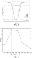
- Fig. 3 shows an example of different curves of attenuation of an embodiment of a band limiter.
- the upper curve show zero attenuation (0 dB), whereas the lowest curve illustrates 10 dB attenuation (-10 dB).
- the loudspeaker plays a single tone with a duration of 200 ms, i.e. a tone burst.
- the maximum distortion about 7.5 %, occurs for tones with a frequency near Fc, i.e. a clearly audible distortion.
- attenuation of the input signal to the loudspeaker in this frequency range helps to reduce the resulting distortion.
- the invention provides a method and a device for reducing distortion from an associated loudspeaker acoustically mounted such that it exhibits a lower resonance frequency Fc.
- a limited frequency band, including Fc, of an audio input signal is attenuated.
- the amount of attenuation to be applied to this limited signal frequency range is determined in response to the peak signal level in this limited signal frequency range so as to only apply an attenuation when the signal level in this frequency range exceeds a predetermined level.
Description
- The present invention relates to the field of signal processing, especially audio signal processing, and more specifically processing of audio signals for playback by small loudspeakers. More specifically, the invention provides a processor and a method for reducing distortion produced by small loudspeakers, and/or increasing the possible acoustic output for such loudspeakers, and/or possibly reducing the risk of damaging the loudspeakers.
- Small loudspeaker units are used in many devices today for reproducing audio signals in compact portable audio devices, e.g. mobile phones, media players, car audio systems and the like. Due to the small size, such loudspeakers have a limited maximum acoustic output, a limited dynamic range, and especially a limited low frequency output. When the dynamic capability of a small loudspeaker is exceeded, the result is a severely distorted audio signal. Especially, the distortion is clearly audible on audio signal including a few pure tones, e.g. as popular ring tones used by many Japanese in their mobile phones.
- A number of known solutions exist for processing the electric signal applied to a small loudspeaker in order to remedy the limited capacity of the loudspeaker, if a low distortion signal is required: reduce the overall level and accept a low acoustic output, sharply filter out low frequency content, or limit the level by means of a compressor.
- An example of such a processing of an audio signal is given by
JP2000253484 - Thus, according to the above description, it is an object of the present invention to provide a simple and effective processor and processing method for preprocessing an audio signal before applying it to a small loudspeaker, so as to increase the acoustic output of the loudspeaker without severely affecting sound quality due to distortion. Alternatively, the goal is to maintain an acoustic output while lower the distortion.
- In a first aspect, the invention provides a device arranged for application to an associated loudspeaker acoustically mounted such that it exhibits a lower resonance frequency. The device comprises
- an input arranged to receive an audio input signal,
- a filter section arranged to receive the audio input signal and to attenuate a limited frequency band thereof and generate a modified audio signal accordingly, wherein the limited frequency band includes said lower resonance frequency of the associated loudspeaker, and
- an output arranged to output the modified audio signal as an audio output signal.
- Such device is advantageous, since it allows reproduction of sound with a miniature or micro-speaker with reduced distortion. Typical loudspeakers where the invention is advantageous are loudspeaker with a small diaphragm area and which are mounted such that its lower resonance frequency Fc is rather high, e.g. 1 kHz, as in many mobile phones and the like. The free air resonance frequency of the loudspeaker is typically lower, but due to a small back volume the resulting lower resonance frequency Fc often becomes rather high. The invention is based on the insight that by attenuating a limited frequency band including the Fc, e.g. centred around Fc (on a logarithmic frequency scale), it is possible to limit large diaphragm excursions of the loudspeaker which occurs when applying sound around Fc. Such large excursions of the diaphragm will at higher signal levels lead to severe audible non-linear distortion, and potentially they may damage the loudspeaker. Such severe distortion can be reduced or even eliminated by proper attenuation of the limited frequency band around Fc. Since the attenuated frequency band is limited, e.g. only 1 octave wide or even narrower such as 1/3-2/3 octaves wide, the negative audible effect of such attenuation is very limited, and in many cases not even audible. Such as 3-6 dB of attenuation at high signal levels in said frequency band can dramatically reduce distortion from a small loudspeaker, thus leading to either improved sound quality and/or increased effective acoustic output from the small loudspeaker at audio frequencies above Fc, but in many cases also below Fc.
- In a digital signal processing chain, the invention should preferably be present just prior to digital to analog conversion resulting in the analog signal to drive the loudspeaker.
- In preferred embodiments, the limited frequency band has a bandwidth of less than 2 octaves, such as less than 1 octave, such as less than 2/3 octaves, such as less than 1/3 octave. The limited frequency band may be centred around said lower resonance frequency of the associated loudspeaker. The bandwidth optimal in each case will depend on the loudspeaker and the acoustical environment where it is mounted. A more effective distortion protection can be achieved with a rather wide bandwidth, whereas the most inaudible processing is obtained with a narrow bandwidth.
- The invention comprises a gain control unit arranged to control said attenuation in the limited frequency band. The gain control unit may be arranged to detect a level of the audio input signal within the limited frequency band and to provide said attenuation according to a predetermined attenuation scheme. Said scheme may include detecting whether a peak level of the audio input signal within the limited frequency band exceeds a predetermined maximum level, and determining said attenuation accordingly to ensure that the modified audio signal does not exceed the predetermined maximum level. Said predetermined maximum level is preferably selected such in relation to the associated loudspeaker that the audio output signal will not cause the loudspeaker to perform a diaphragm excursion exceeding its limit.
- The gain control unit is preferably designed such, that zero attenuation is provided most of the time when signal levels are low enough to ensure that the loudspeaker diaphragm will not reach excursions causing severe distortion. Especially, an attenuation Att (in dB) should preferably be determined in response to a detected peak signal level P (in dB) such that a predetermined maximum allowable level ML (in dB), determined in accordance with the capability of the loudspeaker, e.g. according to:

- Thus, with ML = 100 dB, and a detected peak level P exceeding this, e.g. P = 110 dB, an attenuation of A = 10 dB will be determined, thus leading to a resulting signal level in the frequency band which has a peak level equal to the maximum allowed, i.e. ML. ML can be selected according to the application to include a safety margin to ensure that the loudspeaker is never overloaded, or it can be set to a more aggressive value allowing slightly overloading the loudspeaker. As mentioned, for many signals, the attenuation will preferably be zero, thus leaving the processing inactive. However, in case of signals with high levels within the frequency band including Fc, especially tone complexes with large onsets, the attenuation can effectively ensure that severe audible distortion is avoided.
- It is to be understood, that the filter section may be implemented in various ways, using various types of filters with various cut off slope steepness etc. In one implementation, the filter section may comprise a band pass filter arranged to band pass filter the audio input signal to said limited frequency band, and a band stop filter arranged to band stop filter the audio input signal with the stop band being said limited frequency band. Outputs from the band pass filter and the band stop filter may then be summed to generate the audio output signal.
- The device may be designed to accept an audio input signal with a plurality of audio channels, such as a stereo signal, and wherein the audio channels are processed to form an audio output signal with a corresponding plurality of audio channels. The audio input signal may be analog or digital, and also the audio output signal may be analog or digital. Preferably, the filter section and the attenuation is implemented by means of a digital processor programmed to perform the required signal processing.
- The device may comprise a loudspeaker acoustically mounted such that it exhibits said lower resonance frequency, and a power amplifier connected to drive the loudspeaker according to the audio output signal. Especially, the device may be a mobile device, such as portable audio device, portable video devices, and portable players. More specifically, the device may be one of: a mobile phone, a tablet, a laptop, and a personal navigation device. However, it is to be understood that the invention may be useful in combination to any application where an acoustic output from a small loudspeaker is required with a minimum of audible distortion. Especially, the loudspeaker is small, i.e. has a diaphragm area of less than 10 cm2, such as less than 5 cm2, such as less than 2 cm2, such as less than 1 cm2. The loudspeaker may be further acoustically mounted, e.g. a closed or vented cabinet, such that the lower resonance frequency is above 100 Hz, such as above 300 Hz, such as above 500 Hz, such as above 800 Hz, such as above 1 kHz. Especially, the lower resonance frequency may be between 500 Hz and 2 kHz, such as between 700 Hz and 1.5 kHz.
- In a second aspect, the invention provides a method for reducing distortion from an associated loudspeaker acoustically mounted such that it exhibits a lower resonance frequency, the method comprising attenuating a limited frequency band of an audio input signal, wherein the limited frequency band includes said lower resonance frequency.
- In a third aspect, the invention provides a computer executable program code arranged to perform the method according to the second aspect, such as a computer executable program code stored on a data carrier. The program code may be implemented on any type of audio processing platform, e.g. a sound card in a computer, a general processor in a mobile device e.g.
- It is appreciated that the same advantages and embodiments described for the first aspect apply as well for the second and third aspects. Further, it is appreciated that the described embodiments can be intermixed in any way between all the mentioned aspects.
- The invention will now be described in more detail with regard to the accompanying figures of which
-
Fig. 1 illustrates a block diagram of a possible implementation of the invention, -
Fig. 2 illustrates another block diagram of a stereo device embodiment, -
Fig. 3 illustrates examples of frequency band attenuations for an example of a loudspeaker with Fc = 1 kHz, and -
Fig. 4 illustrates calculated total harmonic distortion versus frequency for a loudspeaker with Fc = 1.3 kHz. - The figures illustrate specific ways of implementing the present invention and are not to be construed as being limiting to other possible embodiments falling within the scope of the attached claim set.
-
Fig. 1 illustrates a device embodiment in block diagram form taking an audio signal A_in as input. A miniature loudspeaker L with lower resonance frequency Fc = 1 kHz, e.g. resulting from the loudspeaker L being mounted in a mobile device cabinet which causes the lower resonance frequency Fc to be higher than the free air resonance frequency of the loudspeaker L. The large box illustrates the signal processing which is preferably implemented as program code of a processor system, e.g. the main processor of a mobile device. This processing is preferably the last part of a digital audio processing chain, since it is important that the correct signal level is detected to ensure that the resulting output signal A_out is the actual signal reaching the loudspeaker L, e.g. taking into account a possible gain in an intermediate power amplifier PA driving the loudspeaker L. - The signal processing according to the invention can be interpreted as a "band limiter", since it basically detects and attenuates, i.e. limits signal level, in a narrow frequency band around the lower resonance frequency Fc of the loudspeaker L. Thus, it is possible, within this narrow frequency range, e.g. 1/3-2/3 octave wide, to control the signal level in this range to ensure that the large diaphragm excursions which occur around Fc will be limited such that the diaphragm will not reach its maximum amplitude - not even during onsets of demanding sound signals with high energy level in the range around Fc. This reduces distortion of the loudspeaker L. Thus, better sound quality can be obtained, and/or more acoustic output can be obtained from a small loudspeaker. Interfering only with a narrow frequency band, normally only within short periods during demanding signal onsets, the audible degrading due to the attenuation is minimal if audible at all. Even if slightly audible, this effect is preferred to the severe non-linear distortion otherwise resulting.
- In the example shown in
Fig. 1 , the band limiter is implemented as a band pass filter BPF and a band stop filter BSF, both operating on the same frequency range, namely a frequency range with a bandwidth BW of less than 1 octave, e.g. 2/3 octaves, and centred around Fc. The input signal A_in is applied to both filters BPF, BSF, and a gain control unit GC detects a peak level of an output of the band pass filter BPF, i.e. the peak level of the signal present within the frequency range around Fc. With a predetermined maximum allowed band pass peak level MBPP (e.g. -10 dB re. full scale), the gain control unit GC determines the gain factor to be applied to the output of the band pass filter BPF so as to obtain a resulting attenuation of the signal level within this band according to a predetermined attenuation scheme. The rest of the input signal A_in, i.e. the output of the band stop filter BSF, is finally added to the attenuated version of the output of the band pass filter BPF to form the output signal A_out. This output signal A_out is then digital to analog converted and applied to the power amplifier PA driving the loudspeaker L. - The attenuation scheme applied by the gain control unit GC can be selected differently, however it may be preferred that the attenuation can be graduated and adjusted based on the detected peak level. Preferably, such that a minimum possible attenuation is selected to ensure that MBPP is not exceeded, e.g. by determining the attenuation Att continuously along with the detected peak level P e.g. according to: Att = P - MBPP (all in dB), when P exceeds MBPP, otherwise Att = 0 dB is selected. Alternatively, a simple scheme is to apply zero attenuation at low signal levels and then apply a fixed attenuation, e.g. 10 dB attenuation, when the detected peak level exceeds MBPP. During most normal operation, the attenuation will thus be zero dB, i.e. the resulting processing is inactive and thus does not influence sound quality. However, during onsets with high signal levels at frequencies around Fc, the processing will effectively protect the loudspeaker L from large diaphragm excursions, and thus severe audible distortion can be eliminated.
-
Fig. 2 shows an example with a band limiter BL as explained in connection withFig. 2 with Fc, BW, and MBPP as input parameters. The band limiter BL is here implemented on a processor P which also handles a pre-equalizing Eq, e.g. to compensate unequal frequency response of the loudspeakers used, of the audio input signal, here shown as a stereo PCM signal. In such case, the band limiter BL has separate path ways for the two stereo signals, here illustrated as a stereo PCM output signal to be applied to a stereo power amplifier PA which drives a set of stereo loudspeakers. -
Fig. 3 shows an example of different curves of attenuation of an embodiment of a band limiter. In the illustrated example, a loudspeaker with Fc = 1 kHz is used, and thus attenuation of the input signal can be applied in a rather narrow band around this frequency, so as to obtain a resulting output signal without severe signal peaks around Fc which can lead to distortion. The upper curve show zero attenuation (0 dB), whereas the lowest curve illustrates 10 dB attenuation (-10 dB). -
Fig. 4 shows a result of a calculation of total harmonic distortion THD for a miniature loudspeaker mounted in a cabinet resulting in a lower resonance frequency of Fc = 1.3 kHz (dashed vertical line). The loudspeaker plays a single tone with a duration of 200 ms, i.e. a tone burst. As seen, the maximum distortion about 7.5 %, occurs for tones with a frequency near Fc, i.e. a clearly audible distortion. Thus, attenuation of the input signal to the loudspeaker in this frequency range helps to reduce the resulting distortion. However, what is not illustrated, and potentially more audible, is the non-linear distortion resulting from even a temporally short overload of the loudspeaker diaphragm, e.g. during onset of a tone or complex of tones in the frequency range near Fc, which will lead to a severe audible distortion clearly exceeding 10 %. Such severe distortion can be eliminated with application of the invention. - To sum up: the invention provides a method and a device for reducing distortion from an associated loudspeaker acoustically mounted such that it exhibits a lower resonance frequency Fc. A limited frequency band, including Fc, of an audio input signal is attenuated. Hereby distortion due to large diaphragm excursions in the frequency range around Fc can be eliminated. Especially, the amount of attenuation to be applied to this limited signal frequency range is determined in response to the peak signal level in this limited signal frequency range so as to only apply an attenuation when the signal level in this frequency range exceeds a predetermined level. Hereby, it is possible to take into account the properties of a miniature loudspeaker and ensure that sufficient attenuation is applied so as to avoid maximum diaphragm excursions which result in severe audible distortion. Thus, by controlling this attenuation in a narrow frequency band, e.g. 1 octave or even down to such as 1/3 octave, severe audible distortion can be eliminated, and the negative audible effect of such "band limitation" is hardly audible since the frequency range is so narrow. Most of the time the attenuation effect is completely inactive, since its effect is only required when large peak levels occur in the range near Fc.
- Although the present invention has been described in connection with the specified embodiments, it should not be construed as being in any way limited to the presented examples. The scope of the present invention is to be interpreted in the light of the accompanying claim set. In the context of the claims, the terms "including" or "includes" do not exclude other possible elements or steps. Also, the mentioning of references such as "a" or "an" etc. should not be construed as excluding a plurality. The use of reference signs in the claims with respect to elements indicated in the figures shall also not be construed as limiting the scope of the invention. Furthermore, individual features mentioned in different claims, may possibly be advantageously combined, and the mentioning of these features in different claims does not exclude that a combination of features is not possible and advantageous.
Claims (12)
- A device arranged for application to an associated loudspeaker (L) acoustically mounted such that it exhibits a lower resonance frequency (Fc),- an input arranged to receive an audio input signal (A_in),- a filter section (BPF, BSF) arranged to receive the audio input signal (A_in) and to provide an attenuation in a limited frequency band thereof and generate a modified audio signal accordingly, wherein the limited frequency band includes said lower resonance frequency (Fc) of the associated loudspeaker (L),- an output arranged to output the modified audio signal as an audio output signal (A_out), and- a gain control unit (GC) arranged to control said attenuation in the limited frequency band, wherein the gain control (GC) unit is arranged to detect a level of the audio input signal (A_in) within the limited frequency band and to provide said attenuation according to a predetermined attenuation scheme, wherein said scheme includes detecting whether a peak level of the audio input signal (A_in) within the limited frequency band exceeds a predetermined maximum level (MBPP), and determining said attenuation accordingly to ensure that the modified audio signal does not exceed the predetermined maximum level (MBPP).
- Device according to claim 1, wherein the limited frequency band has a bandwidth (BW) of less than 2 octaves.
- Device according to claim 2, wherein the limited frequency band is centred around said lower resonance frequency (Fc) of the associated loudspeaker (L).
- Device according to any of the preceding claims, wherein said predetermined maximum level (MBPP) is selected such in relation to the associated loudspeaker (L) that the audio output signal (A_out) will not cause the loudspeaker (L) to perform a diaphragm excursion exceeding its limit.
- Device according to any of the preceding claims, wherein the filter section (BPF, BSF) comprises a band pass filter (BPF) arranged to band pass filter the audio input signal (A_in) to said limited frequency band, and a band stop filter (BSF) arranged to band stop filter the audio input signal (A_in) with the stop band being said limited frequency band.
- Device according to any of the preceding claims, wherein the audio input signal (A_in) includes a plurality of audio channels, and wherein the audio channels are processed to form an audio output signal (A_out) with a corresponding plurality of audio channels.
- Device according to any of the preceding claims, comprising a loudspeaker (L) acoustically mounted such that it exhibits said lower resonance frequency (Fc), and a power amplifier (PA) connected to drive the loudspeaker (L) according to the audio output signal (A_out).
- Device according to claim 7, wherein the loudspeaker (L) has a diaphragm area of less than 10 cm2.
- Device according to claim 8, wherein the loudspeaker is acoustically mounted such that the lower resonance frequency is above 100 Hz.
- Device according to any of the preceding claims, wherein the device is one of: a portable audio device, a portable video device, and a portable player, such as a mobile phone, a tablet, a laptop, or a personal navigation device.
- A method for reducing distortion from an associated loudspeaker (L) acoustically mounted such that it exhibits a lower resonance frequency (Fc), the method comprising attenuating a limited frequency band of an audio input signal (A_in), wherein the limited frequency band includes said lower resonance frequency (Fc), wherein the method further comprises controlling said attenuation in the limited frequency band, detecting a level of the audio input signal (A_in) within the limited frequency band and providing said attenuation according to a predetermined attenuation scheme, wherein said scheme includes detecting whether a peak level of the audio input signal (A_in) within the limited frequency band exceeds a predetermined maximum level (MBPP), and determining said attenuation accordingly to ensure that the modified audio signal does not exceed the predetermined maximum level (MBPP).
- Computer executable program code arranged to perform the method according to claim 11.
Priority Applications (1)
| Application Number | Priority Date | Filing Date | Title |
|---|---|---|---|
| EP11191329.9A EP2600636B8 (en) | 2011-11-30 | 2011-11-30 | Distortion reduction for small loudspeakers by band limiting |
Applications Claiming Priority (1)
| Application Number | Priority Date | Filing Date | Title |
|---|---|---|---|
| EP11191329.9A EP2600636B8 (en) | 2011-11-30 | 2011-11-30 | Distortion reduction for small loudspeakers by band limiting |
Publications (3)
| Publication Number | Publication Date |
|---|---|
| EP2600636A1 EP2600636A1 (en) | 2013-06-05 |
| EP2600636B1 true EP2600636B1 (en) | 2017-03-22 |
| EP2600636B8 EP2600636B8 (en) | 2017-05-03 |
Family
ID=45063041
Family Applications (1)
| Application Number | Title | Priority Date | Filing Date |
|---|---|---|---|
| EP11191329.9A Active EP2600636B8 (en) | 2011-11-30 | 2011-11-30 | Distortion reduction for small loudspeakers by band limiting |
Country Status (1)
| Country | Link |
|---|---|
| EP (1) | EP2600636B8 (en) |
Families Citing this family (2)
| Publication number | Priority date | Publication date | Assignee | Title |
|---|---|---|---|---|
| US10142731B2 (en) * | 2016-03-30 | 2018-11-27 | Dolby Laboratories Licensing Corporation | Dynamic suppression of non-linear distortion |
| EP3226412B1 (en) * | 2016-03-30 | 2021-10-27 | Dolby Laboratories Licensing Corporation | Dynamic suppression of non-linear distortion |
Family Cites Families (3)
| Publication number | Priority date | Publication date | Assignee | Title |
|---|---|---|---|---|
| JP2000253484A (en) * | 1999-03-02 | 2000-09-14 | Sony Corp | Speaker driving device and acoustic equipment provided with the same |
| JP4666229B2 (en) * | 2006-10-18 | 2011-04-06 | ソニー株式会社 | Audio playback device |
| US8194869B2 (en) * | 2010-03-17 | 2012-06-05 | Harman International Industries, Incorporated | Audio power management system |
-
2011
- 2011-11-30 EP EP11191329.9A patent/EP2600636B8/en active Active
Non-Patent Citations (1)
| Title |
|---|
| None * |
Also Published As
| Publication number | Publication date |
|---|---|
| EP2600636A1 (en) | 2013-06-05 |
| EP2600636B8 (en) | 2017-05-03 |
Similar Documents
| Publication | Publication Date | Title |
|---|---|---|
| JP5602309B2 (en) | Method and system for controlling distortion in a critical frequency band of an audio signal | |
| JP6436934B2 (en) | Frequency band compression using dynamic threshold | |
| US9197181B2 (en) | Loudness enhancement system and method | |
| JP5488389B2 (en) | Acoustic signal processing device | |
| TWI535299B (en) | Bass enhancement system and method thereof | |
| US20110002467A1 (en) | Dynamic enhancement of audio signals | |
| US9344051B2 (en) | Apparatus, method and storage medium for performing adaptive audio equalization | |
| US20120128178A1 (en) | Sound reproducing apparatus, sound reproducing method, and program | |
| JP5012995B2 (en) | Audio signal processing apparatus and audio signal processing method | |
| JP2013172454A (en) | Method, device for increasing audio articulation, and computer device | |
| AU2009242464A1 (en) | System and method for dynamic sound delivery | |
| JP2009175420A (en) | Sound correction device | |
| EP2031902A2 (en) | Audio-signal processing apparatus and method | |
| JPWO2007119362A1 (en) | Audio circuit | |
| KR20140055932A (en) | Apparatus and method for keeping output loudness and quality of sound among differernt equalizer modes | |
| JP5682539B2 (en) | Sound playback device | |
| US8254590B2 (en) | System and method for intelligibility enhancement of audio information | |
| EP2600636B1 (en) | Distortion reduction for small loudspeakers by band limiting | |
| CN113031904B (en) | Control method and electronic equipment | |
| JP7427531B2 (en) | Acoustic signal processing device and acoustic signal processing program | |
| US9240764B2 (en) | Apparatus and method for preventing acoustic shock of portable terminal | |
| JP2005184154A (en) | Unit and method for automatic gain control | |
| JP3594910B2 (en) | Audio processing device and electronic apparatus having the audio processing device | |
| CN116778949A (en) | Personalized loudness compensation method, device, computer equipment and storage medium | |
| CN116634221A (en) | Multi-channel audio source automatic mixing method, system, device and medium based on Android system |
Legal Events
| Date | Code | Title | Description |
|---|---|---|---|
| PUAI | Public reference made under article 153(3) epc to a published international application that has entered the european phase |
Free format text: ORIGINAL CODE: 0009012 |
|
| AK | Designated contracting states |
Kind code of ref document: A1 Designated state(s): AL AT BE BG CH CY CZ DE DK EE ES FI FR GB GR HR HU IE IS IT LI LT LU LV MC MK MT NL NO PL PT RO RS SE SI SK SM TR |
|
| AX | Request for extension of the european patent |
Extension state: BA ME |
|
| 17P | Request for examination filed |
Effective date: 20131205 |
|
| RBV | Designated contracting states (corrected) |
Designated state(s): AL AT BE BG CH CY CZ DE DK EE ES FI FR GB GR HR HU IE IS IT LI LT LU LV MC MK MT NL NO PL PT RO RS SE SI SK SM TR |
|
| RIC1 | Information provided on ipc code assigned before grant |
Ipc: H04R 3/00 20060101AFI20160812BHEP Ipc: H04R 3/04 20060101ALI20160812BHEP |
|
| GRAP | Despatch of communication of intention to grant a patent |
Free format text: ORIGINAL CODE: EPIDOSNIGR1 |
|
| INTG | Intention to grant announced |
Effective date: 20161011 |
|
| GRAS | Grant fee paid |
Free format text: ORIGINAL CODE: EPIDOSNIGR3 |
|
| GRAA | (expected) grant |
Free format text: ORIGINAL CODE: 0009210 |
|
| AK | Designated contracting states |
Kind code of ref document: B1 Designated state(s): AL AT BE BG CH CY CZ DE DK EE ES FI FR GB GR HR HU IE IS IT LI LT LU LV MC MK MT NL NO PL PT RO RS SE SI SK SM TR |
|
| REG | Reference to a national code |
Ref country code: GB Ref legal event code: FG4D |
|
| RAP2 | Party data changed (patent owner data changed or rights of a patent transferred) |
Owner name: GOERTEK EUROPE APS |
|
| REG | Reference to a national code |
Ref country code: CH Ref legal event code: EP |
|
| REG | Reference to a national code |
Ref country code: AT Ref legal event code: REF Ref document number: 878796 Country of ref document: AT Kind code of ref document: T Effective date: 20170415 |
|
| REG | Reference to a national code |
Ref country code: IE Ref legal event code: FG4D |
|
| REG | Reference to a national code |
Ref country code: DE Ref legal event code: R096 Ref document number: 602011036160 Country of ref document: DE |
|
| REG | Reference to a national code |
Ref country code: NL Ref legal event code: MP Effective date: 20170322 |
|
| PG25 | Lapsed in a contracting state [announced via postgrant information from national office to epo] |
Ref country code: NO Free format text: LAPSE BECAUSE OF FAILURE TO SUBMIT A TRANSLATION OF THE DESCRIPTION OR TO PAY THE FEE WITHIN THE PRESCRIBED TIME-LIMIT Effective date: 20170622 Ref country code: HR Free format text: LAPSE BECAUSE OF FAILURE TO SUBMIT A TRANSLATION OF THE DESCRIPTION OR TO PAY THE FEE WITHIN THE PRESCRIBED TIME-LIMIT Effective date: 20170322 Ref country code: FI Free format text: LAPSE BECAUSE OF FAILURE TO SUBMIT A TRANSLATION OF THE DESCRIPTION OR TO PAY THE FEE WITHIN THE PRESCRIBED TIME-LIMIT Effective date: 20170322 Ref country code: GR Free format text: LAPSE BECAUSE OF FAILURE TO SUBMIT A TRANSLATION OF THE DESCRIPTION OR TO PAY THE FEE WITHIN THE PRESCRIBED TIME-LIMIT Effective date: 20170623 Ref country code: LT Free format text: LAPSE BECAUSE OF FAILURE TO SUBMIT A TRANSLATION OF THE DESCRIPTION OR TO PAY THE FEE WITHIN THE PRESCRIBED TIME-LIMIT Effective date: 20170322 |
|
| REG | Reference to a national code |
Ref country code: LT Ref legal event code: MG4D |
|
| REG | Reference to a national code |
Ref country code: AT Ref legal event code: MK05 Ref document number: 878796 Country of ref document: AT Kind code of ref document: T Effective date: 20170322 |
|
| PG25 | Lapsed in a contracting state [announced via postgrant information from national office to epo] |
Ref country code: LV Free format text: LAPSE BECAUSE OF FAILURE TO SUBMIT A TRANSLATION OF THE DESCRIPTION OR TO PAY THE FEE WITHIN THE PRESCRIBED TIME-LIMIT Effective date: 20170322 Ref country code: RS Free format text: LAPSE BECAUSE OF FAILURE TO SUBMIT A TRANSLATION OF THE DESCRIPTION OR TO PAY THE FEE WITHIN THE PRESCRIBED TIME-LIMIT Effective date: 20170322 Ref country code: BG Free format text: LAPSE BECAUSE OF FAILURE TO SUBMIT A TRANSLATION OF THE DESCRIPTION OR TO PAY THE FEE WITHIN THE PRESCRIBED TIME-LIMIT Effective date: 20170622 Ref country code: SE Free format text: LAPSE BECAUSE OF FAILURE TO SUBMIT A TRANSLATION OF THE DESCRIPTION OR TO PAY THE FEE WITHIN THE PRESCRIBED TIME-LIMIT Effective date: 20170322 |
|
| PG25 | Lapsed in a contracting state [announced via postgrant information from national office to epo] |
Ref country code: NL Free format text: LAPSE BECAUSE OF FAILURE TO SUBMIT A TRANSLATION OF THE DESCRIPTION OR TO PAY THE FEE WITHIN THE PRESCRIBED TIME-LIMIT Effective date: 20170322 |
|
| PG25 | Lapsed in a contracting state [announced via postgrant information from national office to epo] |
Ref country code: RO Free format text: LAPSE BECAUSE OF FAILURE TO SUBMIT A TRANSLATION OF THE DESCRIPTION OR TO PAY THE FEE WITHIN THE PRESCRIBED TIME-LIMIT Effective date: 20170322 Ref country code: AT Free format text: LAPSE BECAUSE OF FAILURE TO SUBMIT A TRANSLATION OF THE DESCRIPTION OR TO PAY THE FEE WITHIN THE PRESCRIBED TIME-LIMIT Effective date: 20170322 Ref country code: CZ Free format text: LAPSE BECAUSE OF FAILURE TO SUBMIT A TRANSLATION OF THE DESCRIPTION OR TO PAY THE FEE WITHIN THE PRESCRIBED TIME-LIMIT Effective date: 20170322 Ref country code: ES Free format text: LAPSE BECAUSE OF FAILURE TO SUBMIT A TRANSLATION OF THE DESCRIPTION OR TO PAY THE FEE WITHIN THE PRESCRIBED TIME-LIMIT Effective date: 20170322 Ref country code: SK Free format text: LAPSE BECAUSE OF FAILURE TO SUBMIT A TRANSLATION OF THE DESCRIPTION OR TO PAY THE FEE WITHIN THE PRESCRIBED TIME-LIMIT Effective date: 20170322 Ref country code: IT Free format text: LAPSE BECAUSE OF FAILURE TO SUBMIT A TRANSLATION OF THE DESCRIPTION OR TO PAY THE FEE WITHIN THE PRESCRIBED TIME-LIMIT Effective date: 20170322 Ref country code: EE Free format text: LAPSE BECAUSE OF FAILURE TO SUBMIT A TRANSLATION OF THE DESCRIPTION OR TO PAY THE FEE WITHIN THE PRESCRIBED TIME-LIMIT Effective date: 20170322 |
|
| REG | Reference to a national code |
Ref country code: FR Ref legal event code: PLFP Year of fee payment: 7 |
|
| PG25 | Lapsed in a contracting state [announced via postgrant information from national office to epo] |
Ref country code: PT Free format text: LAPSE BECAUSE OF FAILURE TO SUBMIT A TRANSLATION OF THE DESCRIPTION OR TO PAY THE FEE WITHIN THE PRESCRIBED TIME-LIMIT Effective date: 20170724 Ref country code: IS Free format text: LAPSE BECAUSE OF FAILURE TO SUBMIT A TRANSLATION OF THE DESCRIPTION OR TO PAY THE FEE WITHIN THE PRESCRIBED TIME-LIMIT Effective date: 20170722 Ref country code: PL Free format text: LAPSE BECAUSE OF FAILURE TO SUBMIT A TRANSLATION OF THE DESCRIPTION OR TO PAY THE FEE WITHIN THE PRESCRIBED TIME-LIMIT Effective date: 20170322 Ref country code: SM Free format text: LAPSE BECAUSE OF FAILURE TO SUBMIT A TRANSLATION OF THE DESCRIPTION OR TO PAY THE FEE WITHIN THE PRESCRIBED TIME-LIMIT Effective date: 20170322 |
|
| REG | Reference to a national code |
Ref country code: DE Ref legal event code: R097 Ref document number: 602011036160 Country of ref document: DE |
|
| PLBE | No opposition filed within time limit |
Free format text: ORIGINAL CODE: 0009261 |
|
| STAA | Information on the status of an ep patent application or granted ep patent |
Free format text: STATUS: NO OPPOSITION FILED WITHIN TIME LIMIT |
|
| PG25 | Lapsed in a contracting state [announced via postgrant information from national office to epo] |
Ref country code: DK Free format text: LAPSE BECAUSE OF FAILURE TO SUBMIT A TRANSLATION OF THE DESCRIPTION OR TO PAY THE FEE WITHIN THE PRESCRIBED TIME-LIMIT Effective date: 20170322 |
|
| 26N | No opposition filed |
Effective date: 20180102 |
|
| PG25 | Lapsed in a contracting state [announced via postgrant information from national office to epo] |
Ref country code: SI Free format text: LAPSE BECAUSE OF FAILURE TO SUBMIT A TRANSLATION OF THE DESCRIPTION OR TO PAY THE FEE WITHIN THE PRESCRIBED TIME-LIMIT Effective date: 20170322 |
|
| PG25 | Lapsed in a contracting state [announced via postgrant information from national office to epo] |
Ref country code: MC Free format text: LAPSE BECAUSE OF FAILURE TO SUBMIT A TRANSLATION OF THE DESCRIPTION OR TO PAY THE FEE WITHIN THE PRESCRIBED TIME-LIMIT Effective date: 20170322 |
|
| PG25 | Lapsed in a contracting state [announced via postgrant information from national office to epo] |
Ref country code: LI Free format text: LAPSE BECAUSE OF NON-PAYMENT OF DUE FEES Effective date: 20171130 Ref country code: CH Free format text: LAPSE BECAUSE OF NON-PAYMENT OF DUE FEES Effective date: 20171130 |
|
| PG25 | Lapsed in a contracting state [announced via postgrant information from national office to epo] |
Ref country code: LU Free format text: LAPSE BECAUSE OF NON-PAYMENT OF DUE FEES Effective date: 20171130 |
|
| REG | Reference to a national code |
Ref country code: BE Ref legal event code: MM Effective date: 20171130 |
|
| REG | Reference to a national code |
Ref country code: IE Ref legal event code: MM4A |
|
| PG25 | Lapsed in a contracting state [announced via postgrant information from national office to epo] |
Ref country code: MT Free format text: LAPSE BECAUSE OF NON-PAYMENT OF DUE FEES Effective date: 20171130 |
|
| PG25 | Lapsed in a contracting state [announced via postgrant information from national office to epo] |
Ref country code: IE Free format text: LAPSE BECAUSE OF NON-PAYMENT OF DUE FEES Effective date: 20171130 |
|
| PG25 | Lapsed in a contracting state [announced via postgrant information from national office to epo] |
Ref country code: BE Free format text: LAPSE BECAUSE OF NON-PAYMENT OF DUE FEES Effective date: 20171130 |
|
| PG25 | Lapsed in a contracting state [announced via postgrant information from national office to epo] |
Ref country code: HU Free format text: LAPSE BECAUSE OF FAILURE TO SUBMIT A TRANSLATION OF THE DESCRIPTION OR TO PAY THE FEE WITHIN THE PRESCRIBED TIME-LIMIT; INVALID AB INITIO Effective date: 20111130 |
|
| PG25 | Lapsed in a contracting state [announced via postgrant information from national office to epo] |
Ref country code: CY Free format text: LAPSE BECAUSE OF NON-PAYMENT OF DUE FEES Effective date: 20170322 |
|
| PG25 | Lapsed in a contracting state [announced via postgrant information from national office to epo] |
Ref country code: MK Free format text: LAPSE BECAUSE OF FAILURE TO SUBMIT A TRANSLATION OF THE DESCRIPTION OR TO PAY THE FEE WITHIN THE PRESCRIBED TIME-LIMIT Effective date: 20170322 |
|
| PG25 | Lapsed in a contracting state [announced via postgrant information from national office to epo] |
Ref country code: TR Free format text: LAPSE BECAUSE OF FAILURE TO SUBMIT A TRANSLATION OF THE DESCRIPTION OR TO PAY THE FEE WITHIN THE PRESCRIBED TIME-LIMIT Effective date: 20170322 |
|
| PG25 | Lapsed in a contracting state [announced via postgrant information from national office to epo] |
Ref country code: AL Free format text: LAPSE BECAUSE OF FAILURE TO SUBMIT A TRANSLATION OF THE DESCRIPTION OR TO PAY THE FEE WITHIN THE PRESCRIBED TIME-LIMIT Effective date: 20170322 |
|
| REG | Reference to a national code |
Ref country code: DE Ref legal event code: R081 Ref document number: 602011036160 Country of ref document: DE Owner name: GN AUDIO A/S, DK Free format text: FORMER OWNER: GOERTEK EUROPE APS, NORDHAVN, DK |
|
| REG | Reference to a national code |
Ref country code: GB Ref legal event code: 732E Free format text: REGISTERED BETWEEN 20210812 AND 20210818 |
|
| P01 | Opt-out of the competence of the unified patent court (upc) registered |
Effective date: 20230522 |
|
| PGFP | Annual fee paid to national office [announced via postgrant information from national office to epo] |
Ref country code: GB Payment date: 20231120 Year of fee payment: 13 |
|
| PGFP | Annual fee paid to national office [announced via postgrant information from national office to epo] |
Ref country code: FR Payment date: 20231115 Year of fee payment: 13 Ref country code: DE Payment date: 20231121 Year of fee payment: 13 |