EP2600516A1 - Power converter - Google Patents
Power converter Download PDFInfo
- Publication number
- EP2600516A1 EP2600516A1 EP11812431.2A EP11812431A EP2600516A1 EP 2600516 A1 EP2600516 A1 EP 2600516A1 EP 11812431 A EP11812431 A EP 11812431A EP 2600516 A1 EP2600516 A1 EP 2600516A1
- Authority
- EP
- European Patent Office
- Prior art keywords
- flow passage
- power
- radiator fins
- group
- conversion device
- Prior art date
- Legal status (The legal status is an assumption and is not a legal conclusion. Google has not performed a legal analysis and makes no representation as to the accuracy of the status listed.)
- Granted
Links
Images









Classifications
-
- H—ELECTRICITY
- H05—ELECTRIC TECHNIQUES NOT OTHERWISE PROVIDED FOR
- H05K—PRINTED CIRCUITS; CASINGS OR CONSTRUCTIONAL DETAILS OF ELECTRIC APPARATUS; MANUFACTURE OF ASSEMBLAGES OF ELECTRICAL COMPONENTS
- H05K7/00—Constructional details common to different types of electric apparatus
- H05K7/20—Modifications to facilitate cooling, ventilating, or heating
-
- H—ELECTRICITY
- H02—GENERATION; CONVERSION OR DISTRIBUTION OF ELECTRIC POWER
- H02M—APPARATUS FOR CONVERSION BETWEEN AC AND AC, BETWEEN AC AND DC, OR BETWEEN DC AND DC, AND FOR USE WITH MAINS OR SIMILAR POWER SUPPLY SYSTEMS; CONVERSION OF DC OR AC INPUT POWER INTO SURGE OUTPUT POWER; CONTROL OR REGULATION THEREOF
- H02M7/00—Conversion of AC power input into DC power output; Conversion of DC power input into AC power output
- H02M7/003—Constructional details, e.g. physical layout, assembly, wiring or busbar connections
-
- H—ELECTRICITY
- H10—SEMICONDUCTOR DEVICES; ELECTRIC SOLID-STATE DEVICES NOT OTHERWISE PROVIDED FOR
- H10W—GENERIC PACKAGES, INTERCONNECTIONS, CONNECTORS OR OTHER CONSTRUCTIONAL DETAILS OF DEVICES COVERED BY CLASS H10
- H10W40/00—Arrangements for thermal protection or thermal control
- H10W40/20—Arrangements for cooling
- H10W40/22—Arrangements for cooling characterised by their shape, e.g. having conical or cylindrical projections
-
- H—ELECTRICITY
- H10—SEMICONDUCTOR DEVICES; ELECTRIC SOLID-STATE DEVICES NOT OTHERWISE PROVIDED FOR
- H10W—GENERIC PACKAGES, INTERCONNECTIONS, CONNECTORS OR OTHER CONSTRUCTIONAL DETAILS OF DEVICES COVERED BY CLASS H10
- H10W40/00—Arrangements for thermal protection or thermal control
- H10W40/40—Arrangements for thermal protection or thermal control involving heat exchange by flowing fluids
- H10W40/47—Arrangements for thermal protection or thermal control involving heat exchange by flowing fluids by flowing liquids, e.g. forced water cooling
-
- H—ELECTRICITY
- H02—GENERATION; CONVERSION OR DISTRIBUTION OF ELECTRIC POWER
- H02M—APPARATUS FOR CONVERSION BETWEEN AC AND AC, BETWEEN AC AND DC, OR BETWEEN DC AND DC, AND FOR USE WITH MAINS OR SIMILAR POWER SUPPLY SYSTEMS; CONVERSION OF DC OR AC INPUT POWER INTO SURGE OUTPUT POWER; CONTROL OR REGULATION THEREOF
- H02M7/00—Conversion of AC power input into DC power output; Conversion of DC power input into AC power output
- H02M7/42—Conversion of DC power input into AC power output without possibility of reversal
- H02M7/44—Conversion of DC power input into AC power output without possibility of reversal by static converters
- H02M7/48—Conversion of DC power input into AC power output without possibility of reversal by static converters using discharge tubes with control electrode or semiconductor devices with control electrode
-
- H—ELECTRICITY
- H10—SEMICONDUCTOR DEVICES; ELECTRIC SOLID-STATE DEVICES NOT OTHERWISE PROVIDED FOR
- H10W—GENERIC PACKAGES, INTERCONNECTIONS, CONNECTORS OR OTHER CONSTRUCTIONAL DETAILS OF DEVICES COVERED BY CLASS H10
- H10W42/00—Arrangements for protection of devices
- H10W42/20—Arrangements for protection of devices protecting against electromagnetic or particle radiation, e.g. light, X-rays, gamma-rays or electrons
-
- H—ELECTRICITY
- H10—SEMICONDUCTOR DEVICES; ELECTRIC SOLID-STATE DEVICES NOT OTHERWISE PROVIDED FOR
- H10W—GENERIC PACKAGES, INTERCONNECTIONS, CONNECTORS OR OTHER CONSTRUCTIONAL DETAILS OF DEVICES COVERED BY CLASS H10
- H10W90/00—Package configurations
Definitions
- the present invention relates to a power conversion device.
- the flow passage control member be arranged such that a minimum distance between the flow passage control member and the group of radiator fins is set equal to or less than a distance between the fins of the group of radiator fins.
- the flow passage control member in the power conversion device of the first or the second aspect, it is preferable that the flow passage control member be continuously distributed in the gap along the flow direction of the cooling medium.
- the flow passage control member in the power conversion device of the third aspect, it is preferable that the flow passage control member have a shape by which the distance between the flow passage control member and the group of radiator fins is decreased along the flow direction of the cooling medium.
- the generated AC power is converted into DC power by a power conversion device 200 as described later, a high-voltage battery 136 is charged with DC power, and charged electric power is used as energy for traveling of a vehicle again.
- electric power which is stored in the high-voltage battery 136 becomes small, rotational energy generated by the engine EGN is converted into AC power using the motor generator MG2.
- the battery 136 can be charged with DC power.
- the transmission of kinetic energy from the engine EGN to the motor generator MG2 is performed by the power distribution mechanism TSM.
- the constitutions of electric circuits of the inverter circuit 140 and the inverter circuit 142 are explained in conjunction with Fig. 2 .
- the inverter circuit 140 and the inverter circuit 142 are extremely similar to each other with respect to the circuit constitution and the manner of operation and hence, the explanation is made hereinafter by taking the inverter circuit 140 as a representing example. Further, in the explanation made hereinafter, an insulated-gate bipolar transistor is used as a semiconductor element, and the insulated-gate bipolar transistor is abbreviated as IGBT hereinafter.
- a metal oxide semiconductor field effect transistor (abbreviated as MOSFET hereinafter) may be used as a switching power semiconductor element.
- MOSFET metal oxide semiconductor field effect transistor
- the diode 156 and the diode 166 become unnecessary.
- an IGBT is suitable for a case where a DC voltage is relatively high
- a MOSFET is suitable for a case where a DC voltage is relatively low.
- the micon generates a pulse-shaped modulated wave based on a comparison between a fundamental wave (sinusoidal wave) based on the voltage command values of the U phase, the V phase and the W phase and a carrier wave (triangular wave), and outputs the generated modulated wave to the driver circuit 174 as a PWM (pulse width modulation) signal.
- a fundamental wave sinusoidal wave
- a carrier wave triangular wave
- the driver circuit 174 in driving the lower arm, outputs a drive signal obtained by amplifying the PWM signal to a gate electrode of the IGBT 330 of the corresponding lower arm.
- the driver circuit 174 in driving the upper arm, amplifies a PWM signal after shifting a level of a reference potential of the PWM signal to a level of a reference potential of the upper arm, and outputs the amplified PWM signal to a gate electrode of the IGBT 328 of the corresponding upper arm as a drive signal.
- Information on the temperature of the series circuit of upper and lower arms 150 is inputted to the micon from a temperature sensor (not shown in the drawing) mounted in the series circuit of upper and lower arms 150. Further, information on a voltage on a DC positive pole side of the series circuit of upper and lower arms 150 is inputted in the micon. The micon performs the overtemperature detection and the overvoltage detection based on these information, and stops the switching operations of all IGBTs 328 and IGBTs 330 when an overtemperature or an overvoltage is detected.
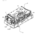
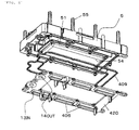
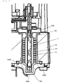
- Fig. 3 to Fig. 5 are views showing the schematic constitution of the power conversion device 200 according to this embodiment, wherein Fig. 3 is a perspective view of the power conversion device 200, Fig. 4 is an exploded perspective view of the power conversion device 200, and Fig. 5 is a cross-sectional view taken along a line A-A in Fig. 3 .
- a shape of the power conversion device 200 as viewed in a plan view is formed into an approximately rectangular shape so that the power conversion device 200 can acquire advantageous effects that the power conversion device 200 can be easily mounted on a vehicle, and can be easily manufactured.
- the power conversion device 200 includes: a cooling base 5 in which the capacitor module 500 and a power modules 1 are housed; and a drive circuit board 2, a control circuit board 3 and the like which are arranged over the cooling base 5.
- the above-mentioned control circuit 172 is mounted on the control circuit board 3.
- a flow passage 51 through which a cooling medium flows, and a capacitor housing portion 54 which is formed such that the capacitor housing portion 54 is surrounded by the flow passage 51 are formed.
- the capacitor module 500 is housed in the capacitor housing portion 54, and is cooled through a wall surface of the flow passage 51.
- a plurality of opening portions 50 are formed in the cooling base 5 along the flow passage 51.
- the power module 1 is constituted such that the above-mentioned series circuit of upper and lower arms 150 is housed in the inside of a metal casing, and generates the largest heat value among the electronic parts. Accordingly, the plurality of power modules 1 are inserted into the inside of the flow passage 51 through the opening portions 50 and are directly cooled by a cooling medium.
- An inlet port 13IN and a discharge port 14OUT are formed in a bottom portion of the cooling base 5.
- a cooling medium for example, cooling water flows into the inside of the flow passage 51 through the inlet port 13IN, circulates in the flow passage 51 and, thereafter, is flown out from the discharge port 14OUT.
- Fig. 7 is a view showing a part of the cross-sectional view shown in Fig. 4 in such a manner that a portion of the flow passage portion in which the power modules 1 are housed is shown in an enlarged manner.
- An opening of the flow passage 51 which is formed in the cooling base 5 on a base back surface side is hermetically closed by the lower cover 420.
- a cylindrical portion on which radiator fins 14 are formed is inserted into the flow passage 51 through the opening portion 50 (see Fig. 5 ) and a flange portion 13b is fixed to an upper surface of the cooling base 5.
- the casing 13 is, for reducing a manufacturing cost, formed of an integral-body-type vessel which is formed in such a manner that the forming of the casing 13 into a can shape, the forming of the radiator fins 14, and the forming of the flange portion 13b are performed by forging.
- a gap of approximately 5 to 10 mm is formed between the flange portion 13b and the radiator fins 14.
- the radiator fins 14 and the flange portion 13b may be formed by cutting. Also in this case, a gap into which a tool enters is necessary at the time of cutting a sealing surface of the flange portion 13b and hence, a gap is formed between the flange portion 13b and the radiator fins 14.
- the double-dashed chained line 144 indicates a group of radiator fins.
- a recessed portion is formed on the lower cover 420 which constitutes a bottom surface of the flow passage 51 in a state where the recessed portion conforms to a bottom surface of the power module 1 in shape thus preventing the formation of a space on a bottom surface side through which a cooling medium bypasses.
Landscapes
- Engineering & Computer Science (AREA)
- Power Engineering (AREA)
- Physics & Mathematics (AREA)
- Thermal Sciences (AREA)
- Microelectronics & Electronic Packaging (AREA)
- Inverter Devices (AREA)
- Cooling Or The Like Of Semiconductors Or Solid State Devices (AREA)
Abstract
Description
- The present invention relates to a power conversion device.
- An electric automobile or a hybrid automobile mounts a motor as a power source for a vehicle thereon, and includes a power conversion device such as an inverter for controlling electric power to be supplied to the motor. The power conversion device includes a power module which incorporates a power semiconductor element such as an IGBT therein, a drive circuit which drives the power module, a control circuit for controlling these parts, and a current smoothing capacitor. Since these electronic parts are weak with respect to heat, it is necessary to cool these parts. In many cases, a large-capacity power conversion device with a large heat value is provided with a cooler having the water cooler structure for circulating cooling water therein.
- Among the electronic parts which constitute the power conversion device, the power module is the part which has the largest heat value. To enhance cooling performance of the power module, the double-sided cooling structure which simultaneously cools both surfaces of the semiconductor element is effective. As an example of the double-sided cooling mounting structure of the power module, there has been known the structure described in
patent literature 1. - PTL 1: Japanese patent
4168825 - However, in the structure where a power module is inserted into a water passage, cooling water flows around cooling fins and hence, there exists a drawback that cooling performance of the power module is lowered.
- According to a first aspect of the present invention, there is provided a power conversion device which includes: a flow passage casing in which a flow passage through which a cooling medium flows is formed and an opening portion which is communicated with the flow passage is formed; a power module having a bottomed cylindrical portion in which a power semiconductor element is housed and which is inserted into the flow passage through the opening portion, a flange portion which is formed on an opening of the cylindrical portion and is fixed to the flow passage casing so as to close the opening portion, and a group of radiator fins which are mounted on an outer peripheral surface of the cylindrical portion with a gap of a predetermined distance formed between the flange portion and the group of radiator fins; and a flow passage control member which is arranged in a gap formed between the flange portion and the group of radiator fins, and introduces the cooling medium into the group of radiator fins, wherein power is converted into AC power from DC power or into DC power from AC power by a switching operation of the power semiconductor element.
According to a second aspect of the present invention, in the power conversion device of the first aspect, it is preferable that the flow passage control member be arranged such that a minimum distance between the flow passage control member and the group of radiator fins is set equal to or less than a distance between the fins of the group of radiator fins.
According to a third aspect of the present invention, in the power conversion device of the first or the second aspect, it is preferable that the flow passage control member be continuously distributed in the gap along the flow direction of the cooling medium.
According to a fourth aspect of the present invention, in the power conversion device of the third aspect, it is preferable that the flow passage control member have a shape by which the distance between the flow passage control member and the group of radiator fins is decreased along the flow direction of the cooling medium.
According to a fifth aspect of the present invention, in the power conversion device of the third aspect, it is preferable that the flow passage control member have a shape by which the distance between the flow passage control member and the group of radiator fins becomes minimum at the center in the flow direction of the group of radiator fins, and the distance is gradually increased in terms of being further away from the center in the flow direction.
According to a sixth aspect of the present invention, in the power conversion device of any one of the first to fifth aspects, it is preferable that the flow passage control member be integrally formed with a seal member which is arranged between the flow passage casing and the flange portion. - According to the present invention, cooling performance of the power module can be enhanced.
-
- [
Fig. 1 ]
A control block diagram of a hybrid automobile. - [
Fig. 2 ]
A view for explaining the constitution of an electric circuit of aninverter circuit 140. - [
Fig. 3 ]
A perspective view of apower conversion device 200. - [
Fig. 4 ]
An exploded perspective view of thepower conversion device 200. - [
Fig. 5 ]
A cross-sectional view taken along a line A-A inFig. 3 . - [
Fig. 6 ]
An exploded perspective view of acooling base 5. - [
Fig. 7 ]
An enlarged cross-sectional view showing a portion of thecooling base 5. - [
Fig. 8 ]
A cross-sectional view of apower module 1. - [
Fig. 9 ]
A perspective view showing the external appearance of thepower module 1. - [
Fig. 10 ]
A perspective view showing a shape of aseal member 16. - [
Fig. 11 ]
A plan view showing anopening portion 50 of thecooling base 5. - [
Fig. 12 ]
A view for explaining the manner of operation of a flowpassage control portion 16b. - [
Fig. 13 ]
A view showing a comparison example. - [
Fig. 14 ]
A view showing aseal member 20 on which a flowpassage control portion 20b is formed. - [
Fig. 15 ]
A view for explaining the manner of operation of the flowpassage control portion 20b. - [
Fig. 16 ]
A view showing aseal member 21 on which a flowpassage control portion 21b is formed. - [
Fig. 17 ]
A view showing aseal member 22 and a flowpassage control member 23 which are formed as separate bodies. - [
Fig. 18 ]
A view showing the constitution which uses apusher plate 24. - [
Fig. 19 ]
A view showing the constitution which uses apusher plate 25. - Hereinafter, an embodiment of the present invention is explained in conjunction with drawings.
Fig. 1 is a control block diagram of a hybrid automobile (hereinafter, described as "HEV"). An engine EGN, a motor generator MG1 and a motor generator MG2 generate torques for traveling of a vehicle respectively. The motor generator MG1 and the motor generator MG2 have not only a function of generating a rotational torque but also a function of converting kinetic energy which is applied to the motor generator MG1 or the motor generator MG2 from the outside into electric power. - The motor generators MG1, MG2 are synchronous motors or induction motors, for example, and as described above, are operated as either motors or generators depending on an operation method. When the motor generators MG1, MG2 are mounted on an automobile, it is desirable that the motor generators MG1, MG2 are small-sized motors and can acquire a high output. Accordingly, a permanent-magnet-type synchronous motor in which a magnet such as a neodymium magnet is used is suitable for the motor generators MG1, MG2. Further, heat generated by a rotor of the permanent-magnet-type synchronous motor is smaller than heat generated by a rotor of an induction motor and hence, the permanent-magnet-type synchronous motor is superior to the induction motor as a motor for an automobile also from such a viewpoint.
- An output torque of an output side of the engine EGN and an output torque of the motor generator MG2 are transmitted to the motor generator MG1 by way of a power distribution mechanism TSM. A rotational torque from the power distribution mechanism TSM or a rotational torque generated by the motor generator MG1 is transmitted to wheels by way of a transmission TM and a differential gear DIF. On the other hand, at the time of operating regenerative braking, a rotational torque is transmitted to the motor generator MG1 from the wheels, and AC power is generated based on the supplied rotational torque.
- The generated AC power is converted into DC power by a
power conversion device 200 as described later, a high-voltage battery 136 is charged with DC power, and charged electric power is used as energy for traveling of a vehicle again. When electric power which is stored in the high-voltage battery 136 becomes small, rotational energy generated by the engine EGN is converted into AC power using the motor generator MG2. By converting this AC power into DC power using thepower conversion device 200, thebattery 136 can be charged with DC power. The transmission of kinetic energy from the engine EGN to the motor generator MG2 is performed by the power distribution mechanism TSM. - Next, the
power conversion device 200 is explained.Inverter circuits battery 136 viaDC connectors 138 so that the supply/reception of electric power is performed between thebattery 136 and theinverter circuits inverter circuit 140 generates AC power based on DC power supplied from thebattery 136 via theDC connector 138, and supplies the AC power to the motor generator MG1 via anAC terminal 188. The constitution formed of the motor generator MG1 and theinverter circuit 140 is operated as a first electrically-operated power generation unit. - When the motor generator MG2 is to be operated as a motor in the same manner as the motor generator MG1, the
inverter circuit 142 generates AC power based on DC power which is supplied from thebattery 136 via theDC connector 138, and supplies the AC power to the motor generator MG2 via anAC terminal 159. The constitution formed of the motor generator MG2 and theinverter circuit 142 is operated as a second electrically-operated power generation unit. - As the manner of operating the first electrically-operated power generation unit and the second electrically-operated power generation unit, depending on a driving state, there are a case where both the first and second electrically-operated power generation units are operated as a motor or a power generator, and a case where the first and second electrically-operated power generation units are used differently such that one is used as a motor and the other is used as a power generator. Further, there may be a case where one of the first and second electrically-operated power generation units is not operated and is brought into a stop state. In this embodiment, by operating the first electrically-operated power generation unit as an electrically-operated unit using electric power of the
battery 136, the vehicle can be driven using only power of the motor generator MG1. Further, in this embodiment, the charging of thebattery 136 is performed in such a manner the first electrically-operated power generation unit or the second electrically-operated power generation unit is operated as a power generation unit using power of the engine 120 or power from the wheels thus generating electric power. - Although not shown in
Fig. 1 , thebattery 136 is used also as a power source for driving a motor for an auxiliary device. As the motor for an auxiliary device, for example, a motor which drives a compressor of an air conditioner or a motor which drives a hydraulic pump for control is named. DC power is supplied to a power module for an auxiliary device from thebattery 136, and the power module for an auxiliary device generates AC power and supplies the AC power to the motor for an auxiliary device. The power module for an auxiliary device basically has the substantially same circuit constitution and functions as theinverter circuit 140, and controls a phase, a frequency and electric power of an alternating current to be supplied to the motor for an auxiliary device. Thepower conversion device 200 includes acapacitor module 500 for smoothing DC power supplied to theinverter circuit 140. - The
power conversion device 200 includes aconnector 31 for communication for receiving a command from a host control device or for transmitting data indicative of a state of thepower conversion device 200 to the host control device. Acontrol circuit 172 of thepower conversion device 200 calculates controlled variables of the motor generator MG1, the motor generator MG2 and a motor 195 for an auxiliary device based on commands which thecontrol circuit 172 receives via theconnector 31. Further, thecontrol circuit 172 calculates whether the motor generator MG1 or the motor generator MG2 is to be operated as a motor or a generator, generates a control pulse based on a calculation result, and supplies the control pulse to adriver circuit 174 and a driver circuit 350B of a module 350 for an auxiliary device. Thedriver circuit 174 generates a drive pulse for controlling theinverter circuit 140 and theinverter circuit 142 based on the supplied control pulse. - Next, the constitutions of electric circuits of the
inverter circuit 140 and theinverter circuit 142 are explained in conjunction withFig. 2 . Theinverter circuit 140 and theinverter circuit 142 are extremely similar to each other with respect to the circuit constitution and the manner of operation and hence, the explanation is made hereinafter by taking theinverter circuit 140 as a representing example. Further, in the explanation made hereinafter, an insulated-gate bipolar transistor is used as a semiconductor element, and the insulated-gate bipolar transistor is abbreviated as IGBT hereinafter. - A series circuit of upper and
lower arms 150 is constituted of anIGBT 328 and adiode 156 which are operated as an upper arm and anIGBT 330 and adiode 166 which are operated as a lower arm. Theinverter circuit 140 includes these series circuits of upper andlower arms 150 corresponding to three phases, that is, a U phase, a V phase and a W phase of AC power to be outputted. - In this embodiment, these three phases respectively correspond to respective windings of three phases of armature winding of the motor generator MG1. In the series circuit of upper and
lower arms 150 for each of three phases, an AC current is outputted from anintermediate electrode 169 which is a middle portion of the series circuit. Theintermediate electrode 169 is connected to AC bus bars 802, 804 via theAC terminal 159 and theAC terminal 188, wherein theAC terminal 159 and theAC terminal 188 are AC power lines leading to the motor generator MG1, and are explained hereinafter. - A
collector electrode 153 of theIGBT 328 of the upper arm is electrically connected to a positive-pole-side capacitor terminal 506 of thecapacitor module 500 via apositive pole terminal 157. An emitter electrode of theIGBT 330 of the lower arm is electrically connected to a negative-pole-side capacitor terminal 504 of thecapacitor module 500 via anegative pole terminal 158. - As described above, the
control circuit 172 receives control commands from the host control device via theconnector 31; generates control pulses which are control signals for controlling theIGBTs 328 and theIGBTs 330 which constitute the upper arms or the lower arms of the series circuits of upper andlower arms 150 of respective phases which form theinverter circuit 140 based on the control commands; and supplies the control pulses to thedriver circuit 174. - The
driver circuit 174 supplies drive pulses for controlling theIGBTs 328 or theIGBTs 330 which constitute the upper arms or the lower arms of the series circuit of upper andlower arms 150 of respective phases based on the above-mentioned control pulse. TheIGBTs 328 and theIGBTs 330 perform a conduction operation or an interruption operation based on the drive pulses from thedriver circuit 174 thus converting DC power supplied from thebattery 136 into three-phase AC power. The converted power is supplied to the motor generator MG1. - The
IGBT 328 includes thecollector electrode 153, anemitter electrode 155 for signal, and agate electrode 154. TheIGBT 330 includes acollector electrode 163, anemitter electrode 165 for signal, and agate electrode 164. Thediode 156 is electrically connected between thecollector electrode 153 and theemitter electrode 155. Thediode 166 is electrically connected between thecollector electrode 163 and theemitter electrode 165. - A metal oxide semiconductor field effect transistor (abbreviated as MOSFET hereinafter) may be used as a switching power semiconductor element. In this case, the
diode 156 and thediode 166 become unnecessary. As the switching power semiconductor element, an IGBT is suitable for a case where a DC voltage is relatively high, and a MOSFET is suitable for a case where a DC voltage is relatively low. - The
capacitor module 500 includes: the plurality of positive-pole-side capacitor terminals 506; the plurality of negative-pole-side capacitor terminals 504; a positive-pole-sidepower source terminal 509 and a negative-pole-sidepower source terminal 508. DC power of high voltage from thebattery 136 is supplied to the positive-pole-sidepower source terminal 509 and the negative-pole-sidepower source terminal 508 via theDC connector 138, and is supplied to theinverter circuit 140 from the positive-pole-side capacitor terminal 506 and the negative-pole-side capacitor terminal 504 of thecapacitor module 500. - On the other hand, DC power which is obtained by the conversion of AC power into DC power by the
inverter circuit 140 or theinverter circuit 142 is supplied to thecapacitor module 500 from the positive-pole-side capacitor terminal 506 and the negative-pole-side capacitor terminal 504, is supplied to thebattery 136 from the positive-pole-sidepower source terminal 509 and the negative-pole-sidepower source terminal 508 via theDC connector 138, and is stored in thebattery 136. - The
control circuit 172 includes a microcomputer (hereinafter referred to as "micon") for arithmetically processing switching timings of theIGBT 328 and theIGBT 330. As input information to be inputted to the micon, a target torque value which the motor generator MG1 is required to generate, a current value of an electric current supplied to the motor generator MG1 from the series circuit of upper andlower arms 150, and a magnetic pole position of a rotor of the motor generator MG1 are named. - A target torque value is based on a command signal outputted from a host control device not shown in the drawing. A current value is detected based on a detection signal transmitted from a
current sensor 180. A magnetic pole position is detected based on a detection signal outputted from a rotation magnetic pole sensor (not shown in the drawing) such as a resolver mounted on the motor generator MG1. In this embodiment, although a case where thecurrent sensor 180 detects current values of three phases is exemplified, current values amounting to two phases may be detected, and electric currents amounting to three phases may be obtained by calculation. - The micon in the
control circuit 172 calculates current command values on a d axis and a q axis of the motor generator MG1 based on a target torque value, calculates voltage command values on the d axis and the q axis based on the difference between the calculated current command values on the d axis and the q axis and the detected current values on the d axis and the q axis, and converts the calculated voltage command values on the d axis and the q axis into voltage command values of a U phase, a V phase and a W phase based on detected magnetic pole positions. Then, the micon generates a pulse-shaped modulated wave based on a comparison between a fundamental wave (sinusoidal wave) based on the voltage command values of the U phase, the V phase and the W phase and a carrier wave (triangular wave), and outputs the generated modulated wave to thedriver circuit 174 as a PWM (pulse width modulation) signal. - The
driver circuit 174, in driving the lower arm, outputs a drive signal obtained by amplifying the PWM signal to a gate electrode of theIGBT 330 of the corresponding lower arm. Thedriver circuit 174, in driving the upper arm, amplifies a PWM signal after shifting a level of a reference potential of the PWM signal to a level of a reference potential of the upper arm, and outputs the amplified PWM signal to a gate electrode of theIGBT 328 of the corresponding upper arm as a drive signal. - The micon in the
control circuit 172 performs the detection of abnormality (an overcurrent, an overvoltage, an overtemperature or the like) thus protecting the series circuit of upper andlower arms 150. Accordingly, sensing information is inputted to thecontrol circuit 172. For example, information on electric currents which are supplied to an emitter electrode of theIGBT 328 and an emitter electrode of theIGBT 330 is respectively inputted to a corresponding drive part (IC) from theemitter electrode 155 for signal and theemitter electrode 165 for signal of the respective arms. Due to such a constitution, each drive part (IC) performs the overcurrent detection, and stops a switching operation of thecorresponding IGBT 328 orIGBT 330 when an overcurrent is detected thus protecting the correspondingIGBT 328 orIGBT 330 from an overcurrent. - Information on the temperature of the series circuit of upper and
lower arms 150 is inputted to the micon from a temperature sensor (not shown in the drawing) mounted in the series circuit of upper andlower arms 150. Further, information on a voltage on a DC positive pole side of the series circuit of upper andlower arms 150 is inputted in the micon. The micon performs the overtemperature detection and the overvoltage detection based on these information, and stops the switching operations of allIGBTs 328 andIGBTs 330 when an overtemperature or an overvoltage is detected. -
Fig. 3 to Fig. 5 are views showing the schematic constitution of thepower conversion device 200 according to this embodiment, whereinFig. 3 is a perspective view of thepower conversion device 200,Fig. 4 is an exploded perspective view of thepower conversion device 200, andFig. 5 is a cross-sectional view taken along a line A-A inFig. 3 . In thepower conversion device 200 of this embodiment, a shape of thepower conversion device 200 as viewed in a plan view is formed into an approximately rectangular shape so that thepower conversion device 200 can acquire advantageous effects that thepower conversion device 200 can be easily mounted on a vehicle, and can be easily manufactured. Thepower conversion device 200 includes a housing and a lid made of aluminum which are fixed to the transmission TM, and circuit parts of thepower conversion device 200 are housed in the inside of the housing. However, inFig. 3 to Fig. 5 , the illustration of the housing and the lid is omitted. - The
power conversion device 200 includes: a coolingbase 5 in which thecapacitor module 500 and apower modules 1 are housed; and adrive circuit board 2, acontrol circuit board 3 and the like which are arranged over thecooling base 5. The above-mentionedcontrol circuit 172 is mounted on thecontrol circuit board 3. In thecooling base 5, aflow passage 51 through which a cooling medium flows, and acapacitor housing portion 54 which is formed such that thecapacitor housing portion 54 is surrounded by theflow passage 51 are formed. Thecapacitor module 500 is housed in thecapacitor housing portion 54, and is cooled through a wall surface of theflow passage 51. - A plurality of opening
portions 50 are formed in thecooling base 5 along theflow passage 51. Thepower module 1 is constituted such that the above-mentioned series circuit of upper andlower arms 150 is housed in the inside of a metal casing, and generates the largest heat value among the electronic parts. Accordingly, the plurality ofpower modules 1 are inserted into the inside of theflow passage 51 through the openingportions 50 and are directly cooled by a cooling medium. An inlet port 13IN and a discharge port 14OUT are formed in a bottom portion of thecooling base 5. A cooling medium (for example, cooling water) flows into the inside of theflow passage 51 through the inlet port 13IN, circulates in theflow passage 51 and, thereafter, is flown out from the discharge port 14OUT. - The
control circuit board 3 is arranged on an upper portion of aboard base 7 made of aluminum which is fixed to support struts of thecooling base 5, and thedrive circuit board 2 is arranged on a lower side of theboard base 7. Thedrive circuit board 2 and thecontrol circuit board 3 are thermally connected to theboard base 7 made of aluminum so that heat generated in thedrive circuit board 2 and thecontrol circuit board 3 is leaked to a cooling medium in theflow passage 51 from theboard base 7 through support struts 55. Theboard base 7 also functions as an electromagnetic shield for a group of circuits mounted on thedrive circuit board 2 and thecontrol circuit board 3. - The
connector 31 is mounted on thecontrol circuit board 3. Theconnector 31 is connected with an external control device, and the signal transmission is performed between thecontrol circuit 172 mounted on thecontrol circuit board 2 and the external control device such as a host control device. DC power of a low voltage for operating the control circuits in the inside of thepower conversion device 200 is supplied from theconnector 31. Although the direction of a fitting surface of a terminal such as theconnector 31 differs variously depending on a type of a vehicle, particularly in a case of mounting thepower conversion device 200 on a small-sized vehicle, it is preferable to arrange the terminal such that the fitting surface is exposed upwardly from a viewpoint of the restriction imposed due to a size of the inside of an engine room or assembling property. Particularly, when thepower conversion device 200 is arranged above a transmission TM, the operability is enhanced by projecting the fitting surface of the terminal toward a side opposite to a side where the transmission TM is arranged. -
Fig. 6 is an exploded perspective view of thecooling base 5, and is a view of the cooling base as viewed from a bottom surface side. Theflow passage 51 is formed such that theflow passage 51 surrounds thecapacitor housing portion 54. One end of theflow passage 51 is communicated with the inlet port 13IN formed in alower cover 420, and the other end of theflow passage 51 is communicated with the discharge port 14OUT formed in thelower cover 420. By downwardly indenting the lower cover member, projectingportions 406 are formed on thelower cover 420 at positions where theopenings 50 face theflow passage 51 respectively. Distal end portions of thepower modules 1 which are inserted into theflow passage 51 are inserted into the inside of recessed portions formed in the projectingportions 406.Numeral 409 indicates a seal member for sealing a gap formed between thelower cover 420 and thecooling base 5. -
Fig. 7 is a view showing a part of the cross-sectional view shown inFig. 4 in such a manner that a portion of the flow passage portion in which thepower modules 1 are housed is shown in an enlarged manner. An opening of theflow passage 51 which is formed in thecooling base 5 on a base back surface side is hermetically closed by thelower cover 420. With respect to thepower module 1, a cylindrical portion on whichradiator fins 14 are formed is inserted into theflow passage 51 through the opening portion 50 (seeFig. 5 ) and aflange portion 13b is fixed to an upper surface of thecooling base 5. A distal end portion (lower end portion in the drawing) of acylindrical portion 13a of thepower module 1 is inserted into the recessed portion formed in the projectingportion 406 of thelower cover 420. Aseal member 16 is provided to a sealing portion between theflange portion 13b and thecooling base 5, and the openingportion 50 is hermetically sealed by theflange portion 13b. Apart of theseal member 16 is inserted into a gap formed between theflange portion 13b and theradiator fins 14. -
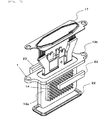
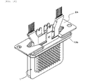
Fig. 8 is a cross-sectional view of thepower module 1, andFig. 9 is a perspective view of the external appearance of thepower module 1. Thepower module 1 is constituted such that the power semiconductor element (IGBT 9 and diode 10) which constitutes the above-mentioned series circuit of upper andlower arms 150 is incorporated in a can-shapedcasing 13 made of aluminum. The IGBT 9 corresponds to IGBTs 154, 164 inFig. 2 and thediode 10 corresponds to thediodes Fig. 2 . Thecasing 13 includes thecylindrical portion 13a in which a transfer mold body is housed, and theflange portion 13b for fixing thepower module 1 to thecooling base 5. As shown inFig. 9 , bolt holes 13c are formed in theflange portion 13b. The IGBT 9 and thediode 10 which are incorporated in thecylindrical portion 13a have both front and back surfaces thereof sandwiched by copper leads 11 which constitute electrodes respectively, and these parts are formed into an integral body by transfer molding using aresin 12.Terminal portions 11b of the copper leads 11 project toward the outside of thecasing 13 from theflange portion 13b. - The
casing 13 plays a role of a radiator which radiates heat generated from the power semiconductor element. Thecasing 13 is constituted such that the plurality of radiator fins (pin fins) 14 are mounted in a raised manner on outer peripheral surfaces ofthick wall portions 130 of thecylindrical portion 13a, that is, on radiation surfaces. The periphery of thethick wall portion 130 forms athin wall portion 131. In manufacturing thepower module 1, a transfer mold body is inserted into the inside of thecasing 13 in a state where the transfer mold body is sandwiched by insulation sheets having an adhesive property. A back surface side of the copper leads 11 is exposed on both front and back surfaces of the transfer mold body, and thethick wall portions 130 are pressed toward the inside of the casing such that the exposed surfaces are brought into close contact with an inner peripheral surface of thecasing 13 with the above-mentioned insulation sheet sandwiched therebetween. When such pressing is performed, thethin wall portions 131 are plastically deformed, and inner peripheral surfaces of thethick wall portions 130 are brought into close contact with and are fixed to both front and back surfaces of the transfer mold body. - The
casing 13 is, for reducing a manufacturing cost, formed of an integral-body-type vessel which is formed in such a manner that the forming of thecasing 13 into a can shape, the forming of theradiator fins 14, and the forming of theflange portion 13b are performed by forging. Here, due to the restriction imposed by a forging mold, a gap of approximately 5 to 10 mm is formed between theflange portion 13b and theradiator fins 14. As a method of forming thecasing 13, for example, theradiator fins 14 and theflange portion 13b may be formed by cutting. Also in this case, a gap into which a tool enters is necessary at the time of cutting a sealing surface of theflange portion 13b and hence, a gap is formed between theflange portion 13b and theradiator fins 14. -
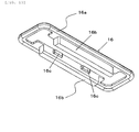
Fig. 10 is a perspective view showing a shape of theseal member 16. Theseal member 16 includes an O-ring portion 16a having the approximately rectangular annular structure, and a pair of flowpassage control portions 16b which are integrally formed inside the O-ring portion 16a. The pair of flowpassage control portions 16b are formed along a long side of the O-ring portion 16a, andprojections 16c are formed on surfaces of the flowpassage control portions 16b which face each other in an opposed manner respectively. When theseal member 16 is mounted in thecasing 13 shown inFig. 8 , theprojections 16c are brought into contact with thethin wall portions 131 formed between theflange portion 13b and thethick wall portions 130. -
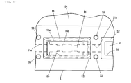
Fig. 11 is a plan view showing the openingportion 50 of thecooling base 5. Aseal groove 52 is formed around the approximatelyrectangular opening portion 50. The O-ring portion 16a of theseal member 16 is placed on an upper surface of theseal groove 52 as indicated by a double-dashed chained line. The flowpassage control portions 16b which are formed on a lower surface side (on a back surface side of the paper that the drawing is on) of theseal member 16 are arranged in the inside of theflow passage 51.Numeral 53 indicates threaded holes for fixing theflange portion 13b of thepower module 1 to the openingportion 50 of thecooling base 5 by bolts. Abroken line 51a indicates a flow passage between the openingportions 50. - In mounting the
power module 1 in the openingportion 50 shown inFig. 11 , firstly, as shown inFig. 9 , theseal member 16 is mounted on thepower module 1 from a lower end of thecylindrical portion 13a as indicated by an arrow thus arranging theseal member 16 on a back surface side (sealing surface side) of theflange portion 13b. Thereafter, thecylindrical portion 13a of thepower module 1 is inserted into the inside of the openingportion 50, and theflange portion 13b is placed on thecooling base 5 such that the O-ring portion 16a of theseal member 16 is arranged in theseal groove 52. Then, apusher plate 17 having the approximately same outer peripheral shape as theflange portion 13b is arranged on theflange portion 13b, and thepusher plate 17 and theflange portion 13b are fastened together to thecooling base 5 usingbolts 18. With the use of thepusher plate 17, it is possible to prevent theflange portion 13b made of aluminum from being deformed at the time of fastening theflange portion 13b by bolts so that uniform sealing can be acquired. -
Fig. 12 andFig. 13 are views for explaining the manner of operation of the flowpassage control portion 16b.Fig. 12 shows a case where the flowpassage control portions 16b are formed in thepower module 1, andFig. 13 shows a case where the flowpassage control portion 16b is not formed in thepower module 1. In bothFig. 12 andFig. 13, (a) is a cross-sectional view taken along a line orthogonal to the flow of a cooling medium, and (b) is a cross-sectional view taken along a line along the flow of the cooling medium. A region surrounded by a double-dashedchained line 144 inFig. 12 andFig. 13 is a region where the plurality ofradiator fins 14 are formed. That is, the double-dashedchained line 144 indicates a group of radiator fins. A recessed portion is formed on thelower cover 420 which constitutes a bottom surface of theflow passage 51 in a state where the recessed portion conforms to a bottom surface of thepower module 1 in shape thus preventing the formation of a space on a bottom surface side through which a cooling medium bypasses. - Firstly, the flow of the cooling medium when the flow
passage control portion 16b is not formed is explained in conjunction withFig. 13 . As shown inFig. 13 (a) which is the cross-sectional view, a gap of a predetermined distance D is formed between theflange portion 13b of thepower module 1 and the group ofradiator fins 144. This is an unavoidable gap due to the restriction imposed from a viewpoint of manufacture as described previously, and the predetermined distance D becomes approximately 5 mm to 10 mm when thecasing 13 is formed by forging. - As shown in
Fig. 13 (b) , from a right side in the drawing, as indicated by an arrow, the cooling medium flows into theflow passage 51 into which thepower module 1 is inserted. While most of the flown cooling medium flows toward a left side in the drawing in such a manner that the cooling medium passes through the gaps formed between theradiator fins 14, some cooling medium flows through aregion 51c where theradiator fins 14 are not formed in a bypassed manner as indicated by astream line 511. As a result, a flow rate of the cooling medium which passes through the portion where theradiator fins 14 are formed is decreased resulting in the lowering of cooling ability of thepower module 1. - On the other hand, as in the case of this embodiment shown in
Fig. 12 , when the flowpassage control portion 16b is arranged in the gap formed between theflange portion 13b and the group ofradiator fins 144, that is, theregion 51c shown inFig. 13 , it is possible to prevent the cooling medium from passing through theregion 51c in a bypassed manner, and also the cooling medium is guided to the group ofradiator fins 144 by the flowpassage control portion 16b as indicated by astream line 510. As a result, a flow rate of the cooling medium which passes through the group ofradiator fins 144 is increased so that a flow speed can be increased whereby the cooling ability of thepower module 1 can be enhanced. - When a blocking member is arranged in the vicinity of an inlet of the
gap region 51c for preventing a cooling medium from entering thegap region 51c, the cooling medium enters theregion 51c by going around the blocking member on a downstream side of the blocking member. Further, a vortex is generated behind the blocking member or the like so that a pressure loss is increased. Accordingly, as shown inFig. 12(b) , it is preferable that the flowpassage control portion 16b is continuously arranged in thegap regions 51c having a length corresponding to a width of the group ofradiator fins 144 along the flow direction of the cooling medium in the inside of thegap region 51c. - In the above-mentioned embodiment, since the flow
passage control portion 16b is integrally formed with the O-ring portion 16a of theflange portion 13b, the number of man-hours of an assembling operation can be reduced, and the constitution is also useful for preventing a person from forgetting the assembling of the flowpassage control portion 16b. - It is not always necessary that the flow
passage control portion 16b occupies the whole space between theflange portion 13b and the group ofradiator fins 144. However, to make the flowpassage control portion 16b function so as to prevent a cooling medium from bypassing the group ofradiator fins 144, assuming a distance between theradiator fins 14 as d1 as shown inFig. 12(a) , it is preferable to set a distance d2 between the flowpassage control portion 16b and the group ofradiator fins 144 smaller than the distance d1 between theradiator fins 14. For example, in a case where theradiator fin 14 is formed of a pin fin, it is preferable to set the distance between the pins to approximately 2 to 3 mm. -
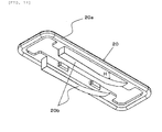
Fig. 14 is a view showing a modification of the above-mentionedseal member 16. Aseal member 20 shown inFig. 14 also is formed of an O-ring portion 20a and flowpassage control portions 20b. The O-ring portion 20a has the same shape as the O-ring portion 16a shown inFig. 10 . On the other hand, the shape of the flowpassage control portion 20b differs from the shape of the flowpassage control portion 16b. That is, the flowpassage control portion 20b has a shape where a height H of the flowpassage control portion 20b is increased gradually in the leftward direction in the drawing. - In mounting the
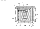
seal member 20 on thepower module 1, as shown inFig. 15 , theseal member 20 is mounted in such a manner that a side of theseal member 20 where the flowpassage control portion 20b has a larger height H is positioned on a more downstream side of the cooling medium. A distance between the flowpassage control portion 20b and the group ofradiator fins 144 is gradually decreased along the flow of the cooling medium and hence, as indicated by a stream line, a cooling medium flows toward the group ofradiator fins 144 along an inclined bottom surface of the flowpassage control portion 20b. In this manner, by forming the flowpassage control portion 20b into a shape where an area of a flow passage is smoothly changed along the flow direction, a straightening effect is imparted to a cooling medium so that a pressure loss can be made small. - The shape of the above-mentioned flow
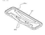
passage control portion 20b may be deformed into a shape of a flowpassage control portion 21b shown inFig. 16 . In the flowpassage control portion 21b shown inFig. 16 , an inclined bottom surface is formed on both of an upstream side and a downstream side of the flow of a cooling medium. That is, the flowpassage control portion 21b is formed into a shape where a distance between the flowpassage control portion 21b and the group ofradiator fins 144 becomes minimum at the center of the group ofradiator fins 144 in the flow direction, and the distance is gradually increased in terms of being further away from the center of the group ofradiator fins 144. In this manner, by forming the flowpassage control portion 21b into a left-and-right symmetrical shape, even when the flow direction of the cooling medium is either the left direction or the right direction inFig. 15 , the substantially same advantageous effect can be acquired. That is, the occurrence of an error in assembling theseal member 20 can be prevented. - By adopting any one of the above-mentioned flow passage control portions described in
Fig. 10 ,Fig. 14 andFig. 16 , a quantity of cooling medium which does not pass through theradiator fins 14 can be reduced so that a flow speed of the cooling medium which hits theradiator fins 14 can be increased and hence, the cooling ability of thepower module 1 can be enhanced. The enhancement of the cooling ability contributes to the miniaturization of the cooling device and the power module. Thepower module 1 is allowed to generate a large quantity of heat value and hence, a size of a power-supply-use power semiconductor can be decreased thus contributing to the reduction of cost. - When the further reduction of a pressure loss is required, it is desirable to adopt the flow
passage control portions Fig. 14 andFig. 16 . On the other hand, when the emphasis is placed on the enhancement of the cooling performance, it is preferable to adopt the flowpassage control portions 16b shown inFig. 10 which has the structure where a cooling medium does not go around between theflange portion 13b and the group ofradiator fins 144. In this manner, the present invention can cope with a plurality of vehicles having different specifications on requirements using thesame power module 1 and hence, the power conversion device of the same type can cope with a plurality of vehicles whereby a development cost and a manufacturing cost can be lowered. - In the above-mentioned embodiment, the O-ring portion of the
flange portion 13b which has a sealing function, and the flow passage control portion which blocks the flow of a cooling medium are integrally formed. However, as shown inFig. 17 , the O-ring portion may be formed as a body separate from the flow passage control portion. In the example shown inFig. 17 , a standard seal material is used as aseal member 22 of theflange portion 13b. Two independent flowpassage control members 23 are arranged between theflange portion 13b and theradiator fins 14. The flowpassage control member 23 shown inFig. 17 has the substantially same shape as the flowpassage control portion 16b shown inFig. 10 . However, the flowpassage control member 23 shown inFig. 17 may have a shape of the flowpassage control portion 20b shown inFig. 14 or a shape of the flowpassage control portion 21b shown inFig. 16 . By adopting such a constitution, a seal member having a standard shape is used as theseal member 22 and hence, it is unnecessary to particularly prepare a dedicated mold so that a manufacturing cost of the seal member can be suppressed. - In the above-mentioned embodiment, the
pusher plate 17 is used for fixing thepower module 1. This is because thecasing 13 is formed using an extremely soft pure-aluminum-based material by forging and hence, when theflange portion 13b is fixed by bolts without using thepusher plate 17, theflange portion 13b is deformed due to a repulsive force of theseal member 16. Accordingly, thepusher plate 17 is formed using a material such as steel. However, to lower a stress generated in thepusher plate 17, the bolt holes 13c through which the bolt passes are formed also in theflange portion 13b of thecasing 13 thus adopting the configuration where thepusher plate 17 and theflange portion 13b are fastened together. Further, as shown inFig. 9 andFig. 17 , positions of thebolt holes 13c formed in theflange portion 13b are displaced from each other. As a result, when a plurality ofpower modules 1 are arranged on one straight line as shown inFig. 5 , the bolts are arranged in a staggered manner so that the total length of the power conversion device in a state where thepower modules 1 are mounted can be shortened. - The arrangement of the
power modules 1 can be changed depending on restriction conditions imposed on a shape of the whole power conversion device and hence, when a pusher plate is used, it is desirable to cope with the change in the arrangement of thepower modules 1 by only changing of the pusher plate without forming bolt holes for fixing by bolts in thepower modules 1 even when the arrangement of thepower modules 1 is changed. -
Fig. 18 shows one example of the constitution where bolt holes are not formed in theflange portion 13b. The bolt holes for fixing by bolts are not formed in theflange portion 13b of thepower module 1 and hence, apusher plate 24 is directly fixed to thecooling base 5 by bolts in place of being fastened together with theflange portion 13b. Accordingly, to absorb the manufacture tolerances of thicknesses of theflange portion 13b and a seal member, a shape of thepusher plate 24 in the vicinity of the bolt hole is formed into a zigzag spring shape. Due to such a constitution, the formation of bolt holes in theflange portion 13b of thepower module 1 becomes unnecessary and hence, various arrangements of thepower modules 1 can be realized using thepower modules 1 having the same shape, and the power conversion device can easily cope with a change in the arrangement of the power modules when the arrangement of thepower modules 1 is changed. - In the example shown in
Fig. 18 , onepusher plate 24 is necessary for every power module. However, in a case of apusher plate 25 shown inFig. 19 , threepower modules 1 are fixed using onepusher plate 25 and hence, the number of bolts can be decreased whereby the number of man-hours in assembling can be decreased. - In the above-mentioned embodiment, the
radiator fins 14 are formed of a pin fin. However, theradiator fins 14 may have other shapes and, for example, the radiator fins may be formed of a straight fin. Although the above-mentionedcasing 13 is integrally formed by forging, even in a case of a cylindrical casing which is formed by other manufacturing methods, the formation of a gap between theflange portion 13b for fixing thepower module 1 to thecooling base 5 and the group ofradiator fins 144 is unavoidable in terms of manufacture. Accordingly, by arranging a flow passage control portion in such a gap, the substantially same advantageous effects as the above-mentioned embodiment can be obtained. Particularly, in the case of the casing shown inFig. 8 , thethin wall portion 131 for plastic deformation is formed between theflange portion 13b and the group ofradiator fins 144 and hence, it is impossible to prevent the further increase of the gap between theflange portion 13b and the group of theradiator fins 144 whereby advantageous effects brought about by the provision of the flow passage control portion is further increased. In the above-mentioned embodiment, the explanation has been made by taking the vehicle-mounted power conversion device mounted on an electric vehicle or a hybrid vehicle as an example. However, provided that the power conversion device is a power conversion device having the cooling structure where a power module is immersed in a cooling medium, the present invention is also applicable to such a power conversion device. - The above-mentioned respective embodiments can be used in a single form respectively or in combination. This is because advantageous effects which can be acquired by the respective embodiments may be acquired independently or synergistically. Further, unless the technical features of the present invention are impaired, the present invention is not limited by the above-mentioned embodiments at all.
- The contents disclosed in the following application based on which priority is claimed are incorporated in this specification in the form of cited literature. Japanese patent application
2010-168813 (filed on July, 28, 2010
Claims (6)
- A power conversion device comprising:a flow passage casing in which a flow passage through which a cooling medium flows is formed and an opening portion which is communicated with the flow passage is formed;a power module having a bottomed cylindrical portion in which a power semiconductor element is housed and which is inserted into the flow passage through the opening portion, a flange portion which is formed on an opening of the cylindrical portion and is fixed to the flow passage casing so as to close the opening portion, and a group of radiator fins which are mounted on an outer peripheral surface of the cylindrical portion with a gap of a predetermined distance formed between the flange portion and the group of radiator fins; anda flow passage control member which is arranged in a gap formed between the flange portion and the group of radiator fins, and introduces the cooling medium into the group of radiator fins, whereinpower is converted into AC power from DC power or into DC power from AC power by a switching operation of the power semiconductor element.
- The power conversion device according to claim 1, wherein the flow passage control member is arranged such that a minimum distance between the flow passage control member and the group of radiator fins is set equal to or less than a distance between the fins of the group of radiator fins.
- The power conversion device according to claim 1 or 2, wherein the flow passage control member is continuously distributed in the gap along the flow direction of the cooling medium.
- The power conversion device according to claim 3, wherein the flow passage control member has a shape by which the distance between the flow passage control member and the group of radiator fins is decreased along the flow direction of the cooling medium.
- The power conversion device according to claim 3, the flow passage control member has a shape by which the distance between the flow passage control member and the group of radiator fins becomes minimum at the center in the flow direction of the group of radiator fins, and the distance is gradually increased as being more away from the center in the flow direction.
- The power conversion device according to any one of claims 1 to 5, wherein the flow passage control member is integrally formed with a seal member which is arranged between the flow passage casing and the flange portion.
Applications Claiming Priority (2)
| Application Number | Priority Date | Filing Date | Title |
|---|---|---|---|
| JP2010168813A JP5439309B2 (en) | 2010-07-28 | 2010-07-28 | Power converter |
| PCT/JP2011/066853 WO2012014842A1 (en) | 2010-07-28 | 2011-07-25 | Power converter |
Publications (3)
| Publication Number | Publication Date |
|---|---|
| EP2600516A1 true EP2600516A1 (en) | 2013-06-05 |
| EP2600516A4 EP2600516A4 (en) | 2018-01-24 |
| EP2600516B1 EP2600516B1 (en) | 2020-09-30 |
Family
ID=45530050
Family Applications (1)
| Application Number | Title | Priority Date | Filing Date |
|---|---|---|---|
| EP11812431.2A Active EP2600516B1 (en) | 2010-07-28 | 2011-07-25 | Power converter |
Country Status (5)
| Country | Link |
|---|---|
| US (1) | US9078376B2 (en) |
| EP (1) | EP2600516B1 (en) |
| JP (1) | JP5439309B2 (en) |
| CN (1) | CN103026605B (en) |
| WO (1) | WO2012014842A1 (en) |
Families Citing this family (28)
| Publication number | Priority date | Publication date | Assignee | Title |
|---|---|---|---|---|
| JP5370448B2 (en) * | 2011-09-19 | 2013-12-18 | 株式会社デンソー | Power converter |
| JP5949286B2 (en) * | 2012-07-31 | 2016-07-06 | 株式会社デンソー | Power converter |
| JP2014072395A (en) | 2012-09-28 | 2014-04-21 | Toyota Industries Corp | Cooling system |
| JP6262422B2 (en) | 2012-10-02 | 2018-01-17 | 昭和電工株式会社 | Cooling device and semiconductor device |
| US9204573B2 (en) * | 2013-05-08 | 2015-12-01 | Kabushiki Kaisha Toshiba | Power conversion apparatus |
| JP6101609B2 (en) * | 2013-09-20 | 2017-03-22 | 日立オートモティブシステムズ株式会社 | Power semiconductor module and power converter using the same |
| US9992915B2 (en) | 2013-10-07 | 2018-06-05 | Hitachi Automotive Systems, Ltd. | Power conversion device |
| US20150138734A1 (en) * | 2013-11-18 | 2015-05-21 | Magna Electronics Inc. | 360 degree direct cooled power module |
| JP6193173B2 (en) * | 2014-04-17 | 2017-09-06 | 日立オートモティブシステムズ株式会社 | Power converter |
| WO2015198411A1 (en) * | 2014-06-25 | 2015-12-30 | 株式会社日立製作所 | Power-module device, power conversion device, and method for manufacturing power-module device |
| DE112015002587B4 (en) * | 2014-06-26 | 2021-04-15 | Hitachi Automotive Systems, Ltd. | POWER SEMICONDUCTOR AND MANUFACTURING METHOD OF THE POWER SEMICONDUCTOR MODULE |
| JP6302803B2 (en) * | 2014-09-09 | 2018-03-28 | 日立オートモティブシステムズ株式会社 | Power semiconductor module, method for manufacturing the same, and power conversion device |
| US10037952B2 (en) * | 2015-02-10 | 2018-07-31 | Mediatek Inc. | Integrated circuit, electronic device and method for transmitting data in electronic device |
| US9978692B2 (en) * | 2015-02-10 | 2018-05-22 | Mediatek Inc. | Integrated circuit, electronic device and method for transmitting data in electronic device |
| WO2017033295A1 (en) * | 2015-08-26 | 2017-03-02 | 日立オートモティブシステムズ株式会社 | Structure |
| JP6593221B2 (en) * | 2016-02-23 | 2019-10-23 | 株式会社デンソー | Power converter |
| WO2017149801A1 (en) * | 2016-03-02 | 2017-09-08 | 三菱電機株式会社 | Power conversion device |
| WO2017187781A1 (en) * | 2016-04-28 | 2017-11-02 | 日立オートモティブシステムズ株式会社 | Power conversion device |
| JP7264159B2 (en) * | 2018-04-06 | 2023-04-25 | ニデック株式会社 | power converter |
| JP7159620B2 (en) * | 2018-05-30 | 2022-10-25 | 富士電機株式会社 | Semiconductor devices, cooling modules, power converters and electric vehicles |
| JP7208757B2 (en) * | 2018-10-03 | 2023-01-19 | 川崎重工業株式会社 | Control device |
| JP7233014B2 (en) * | 2018-12-26 | 2023-03-06 | パナソニックIpマネジメント株式会社 | power converter |
| JP6777203B2 (en) * | 2019-08-09 | 2020-10-28 | 株式会社デンソー | Power converter |
| JP2022188312A (en) * | 2019-11-27 | 2022-12-21 | 日立Astemo株式会社 | Power module and method for manufacturing power module |
| JP7419050B2 (en) | 2019-12-16 | 2024-01-22 | 日立Astemo株式会社 | Power module, power converter, and power module manufacturing method |
| JP7294455B2 (en) * | 2019-12-19 | 2023-06-20 | 東芝三菱電機産業システム株式会社 | Power conversion device and manufacturing method thereof |
| KR102810533B1 (en) * | 2020-02-28 | 2025-05-22 | 현대모비스 주식회사 | Cooling structure of power inverter |
| CN112053999B (en) * | 2020-08-10 | 2022-05-13 | 浙江艾罗网络能源技术股份有限公司 | High-strength insulating pressing block for fixing inverter transistor |
Family Cites Families (9)
| Publication number | Priority date | Publication date | Assignee | Title |
|---|---|---|---|---|
| JPH02210899A (en) * | 1989-02-09 | 1990-08-22 | Fujitsu Ltd | Cooling structure of printed wiring board unit |
| DE19643717A1 (en) * | 1996-10-23 | 1998-04-30 | Asea Brown Boveri | Liquid cooling device for a high-performance semiconductor module |
| JP4168825B2 (en) | 2003-05-07 | 2008-10-22 | トヨタ自動車株式会社 | Semiconductor module and semiconductor module unit equipped with semiconductor module |
| US6992382B2 (en) * | 2003-12-29 | 2006-01-31 | Intel Corporation | Integrated micro channels and manifold/plenum using separate silicon or low-cost polycrystalline silicon |
| JP2005348533A (en) * | 2004-06-03 | 2005-12-15 | Fuji Electric Fa Components & Systems Co Ltd | Inverter device |
| JP5120605B2 (en) * | 2007-05-22 | 2013-01-16 | アイシン・エィ・ダブリュ株式会社 | Semiconductor module and inverter device |
| TWI423403B (en) * | 2007-09-17 | 2014-01-11 | 萬國商業機器公司 | Integrated circuit stack |
| JP5557441B2 (en) * | 2008-10-31 | 2014-07-23 | 日立オートモティブシステムズ株式会社 | Power converter and electric vehicle |
| US8064198B2 (en) * | 2009-06-29 | 2011-11-22 | Honda Motor Co., Ltd. | Cooling device for semiconductor element module and magnetic part |
-
2010
- 2010-07-28 JP JP2010168813A patent/JP5439309B2/en active Active
-
2011
- 2011-07-25 EP EP11812431.2A patent/EP2600516B1/en active Active
- 2011-07-25 CN CN201180036876.6A patent/CN103026605B/en active Active
- 2011-07-25 WO PCT/JP2011/066853 patent/WO2012014842A1/en not_active Ceased
- 2011-07-25 US US13/811,497 patent/US9078376B2/en active Active
Non-Patent Citations (1)
| Title |
|---|
| See references of WO2012014842A1 * |
Also Published As
| Publication number | Publication date |
|---|---|
| CN103026605A (en) | 2013-04-03 |
| EP2600516A4 (en) | 2018-01-24 |
| JP2012029539A (en) | 2012-02-09 |
| US9078376B2 (en) | 2015-07-07 |
| WO2012014842A1 (en) | 2012-02-02 |
| EP2600516B1 (en) | 2020-09-30 |
| JP5439309B2 (en) | 2014-03-12 |
| US20130128646A1 (en) | 2013-05-23 |
| CN103026605B (en) | 2015-09-09 |
Similar Documents
| Publication | Publication Date | Title |
|---|---|---|
| EP2600516B1 (en) | Power converter | |
| JP5851372B2 (en) | Power converter | |
| JP5508357B2 (en) | Power converter | |
| JP4452953B2 (en) | Power converter | |
| JP5422466B2 (en) | Power converter | |
| US8659130B2 (en) | Power module and power module manufacturing method | |
| US9474191B2 (en) | Power semiconductor module | |
| US9419535B2 (en) | Electric power converter | |
| JP5815063B2 (en) | Power converter | |
| WO2011162241A1 (en) | Power conversion device | |
| JP2011217550A (en) | Power conversion apparatus | |
| JP2010245910A (en) | Power conversion device and in-vehicle electric system using the same | |
| WO2014034331A1 (en) | Power conversion apparatus | |
| JP2013005067A (en) | Power conversion apparatus | |
| WO2021225072A1 (en) | Power conversion device | |
| JP2010011671A (en) | Power convertor | |
| JP5623985B2 (en) | Power converter | |
| JP2014166043A (en) | Electric power conversion apparatus | |
| JP2010110066A (en) | Power conversion apparatus | |
| JP6272064B2 (en) | Power converter |
Legal Events
| Date | Code | Title | Description |
|---|---|---|---|
| PUAI | Public reference made under article 153(3) epc to a published international application that has entered the european phase |
Free format text: ORIGINAL CODE: 0009012 |
|
| 17P | Request for examination filed |
Effective date: 20130228 |
|
| AK | Designated contracting states |
Kind code of ref document: A1 Designated state(s): AL AT BE BG CH CY CZ DE DK EE ES FI FR GB GR HR HU IE IS IT LI LT LU LV MC MK MT NL NO PL PT RO RS SE SI SK SM TR |
|
| DAX | Request for extension of the european patent (deleted) | ||
| RA4 | Supplementary search report drawn up and despatched (corrected) |
Effective date: 20180102 |
|
| RIC1 | Information provided on ipc code assigned before grant |
Ipc: H01L 25/07 20060101ALI20171219BHEP Ipc: H01L 23/367 20060101ALI20171219BHEP Ipc: H01L 23/473 20060101ALI20171219BHEP Ipc: H01L 25/18 20060101ALI20171219BHEP Ipc: H02M 7/48 20070101AFI20171219BHEP |
|
| GRAP | Despatch of communication of intention to grant a patent |
Free format text: ORIGINAL CODE: EPIDOSNIGR1 |
|
| STAA | Information on the status of an ep patent application or granted ep patent |
Free format text: STATUS: GRANT OF PATENT IS INTENDED |
|
| INTG | Intention to grant announced |
Effective date: 20200402 |
|
| GRAJ | Information related to disapproval of communication of intention to grant by the applicant or resumption of examination proceedings by the epo deleted |
Free format text: ORIGINAL CODE: EPIDOSDIGR1 |
|
| STAA | Information on the status of an ep patent application or granted ep patent |
Free format text: STATUS: REQUEST FOR EXAMINATION WAS MADE |
|
| GRAP | Despatch of communication of intention to grant a patent |
Free format text: ORIGINAL CODE: EPIDOSNIGR1 |
|
| STAA | Information on the status of an ep patent application or granted ep patent |
Free format text: STATUS: GRANT OF PATENT IS INTENDED |
|
| INTC | Intention to grant announced (deleted) | ||
| INTG | Intention to grant announced |
Effective date: 20200713 |
|
| GRAS | Grant fee paid |
Free format text: ORIGINAL CODE: EPIDOSNIGR3 |
|
| GRAA | (expected) grant |
Free format text: ORIGINAL CODE: 0009210 |
|
| STAA | Information on the status of an ep patent application or granted ep patent |
Free format text: STATUS: THE PATENT HAS BEEN GRANTED |
|
| AK | Designated contracting states |
Kind code of ref document: B1 Designated state(s): AL AT BE BG CH CY CZ DE DK EE ES FI FR GB GR HR HU IE IS IT LI LT LU LV MC MK MT NL NO PL PT RO RS SE SI SK SM TR |
|
| REG | Reference to a national code |
Ref country code: CH Ref legal event code: EP Ref country code: GB Ref legal event code: FG4D |
|
| REG | Reference to a national code |
Ref country code: DE Ref legal event code: R096 Ref document number: 602011068786 Country of ref document: DE Ref country code: AT Ref legal event code: REF Ref document number: 1319834 Country of ref document: AT Kind code of ref document: T Effective date: 20201015 |
|
| REG | Reference to a national code |
Ref country code: IE Ref legal event code: FG4D |
|
| PG25 | Lapsed in a contracting state [announced via postgrant information from national office to epo] |
Ref country code: SE Free format text: LAPSE BECAUSE OF FAILURE TO SUBMIT A TRANSLATION OF THE DESCRIPTION OR TO PAY THE FEE WITHIN THE PRESCRIBED TIME-LIMIT Effective date: 20200930 Ref country code: BG Free format text: LAPSE BECAUSE OF FAILURE TO SUBMIT A TRANSLATION OF THE DESCRIPTION OR TO PAY THE FEE WITHIN THE PRESCRIBED TIME-LIMIT Effective date: 20201230 Ref country code: FI Free format text: LAPSE BECAUSE OF FAILURE TO SUBMIT A TRANSLATION OF THE DESCRIPTION OR TO PAY THE FEE WITHIN THE PRESCRIBED TIME-LIMIT Effective date: 20200930 Ref country code: GR Free format text: LAPSE BECAUSE OF FAILURE TO SUBMIT A TRANSLATION OF THE DESCRIPTION OR TO PAY THE FEE WITHIN THE PRESCRIBED TIME-LIMIT Effective date: 20201231 Ref country code: NO Free format text: LAPSE BECAUSE OF FAILURE TO SUBMIT A TRANSLATION OF THE DESCRIPTION OR TO PAY THE FEE WITHIN THE PRESCRIBED TIME-LIMIT Effective date: 20201230 Ref country code: HR Free format text: LAPSE BECAUSE OF FAILURE TO SUBMIT A TRANSLATION OF THE DESCRIPTION OR TO PAY THE FEE WITHIN THE PRESCRIBED TIME-LIMIT Effective date: 20200930 |
|
| REG | Reference to a national code |
Ref country code: AT Ref legal event code: MK05 Ref document number: 1319834 Country of ref document: AT Kind code of ref document: T Effective date: 20200930 |
|
| PG25 | Lapsed in a contracting state [announced via postgrant information from national office to epo] |
Ref country code: LV Free format text: LAPSE BECAUSE OF FAILURE TO SUBMIT A TRANSLATION OF THE DESCRIPTION OR TO PAY THE FEE WITHIN THE PRESCRIBED TIME-LIMIT Effective date: 20200930 Ref country code: RS Free format text: LAPSE BECAUSE OF FAILURE TO SUBMIT A TRANSLATION OF THE DESCRIPTION OR TO PAY THE FEE WITHIN THE PRESCRIBED TIME-LIMIT Effective date: 20200930 |
|
| REG | Reference to a national code |
Ref country code: NL Ref legal event code: MP Effective date: 20200930 |
|
| REG | Reference to a national code |
Ref country code: DE Ref legal event code: R082 Ref document number: 602011068786 Country of ref document: DE Representative=s name: MERH-IP MATIAS ERNY REICHL HOFFMANN PATENTANWA, DE Ref country code: DE Ref legal event code: R081 Ref document number: 602011068786 Country of ref document: DE Owner name: HITACHI ASTEMO, LTD., HITACHINAKA-SHI, JP Free format text: FORMER OWNER: HITACHI AUTOMOTIVE SYSTEMS, LTD., HITACHINAKA-SHI, IBARAKI, JP |
|
| REG | Reference to a national code |
Ref country code: LT Ref legal event code: MG4D |
|
| PG25 | Lapsed in a contracting state [announced via postgrant information from national office to epo] |
Ref country code: LT Free format text: LAPSE BECAUSE OF FAILURE TO SUBMIT A TRANSLATION OF THE DESCRIPTION OR TO PAY THE FEE WITHIN THE PRESCRIBED TIME-LIMIT Effective date: 20200930 Ref country code: PT Free format text: LAPSE BECAUSE OF FAILURE TO SUBMIT A TRANSLATION OF THE DESCRIPTION OR TO PAY THE FEE WITHIN THE PRESCRIBED TIME-LIMIT Effective date: 20210201 Ref country code: NL Free format text: LAPSE BECAUSE OF FAILURE TO SUBMIT A TRANSLATION OF THE DESCRIPTION OR TO PAY THE FEE WITHIN THE PRESCRIBED TIME-LIMIT Effective date: 20200930 Ref country code: RO Free format text: LAPSE BECAUSE OF FAILURE TO SUBMIT A TRANSLATION OF THE DESCRIPTION OR TO PAY THE FEE WITHIN THE PRESCRIBED TIME-LIMIT Effective date: 20200930 Ref country code: SM Free format text: LAPSE BECAUSE OF FAILURE TO SUBMIT A TRANSLATION OF THE DESCRIPTION OR TO PAY THE FEE WITHIN THE PRESCRIBED TIME-LIMIT Effective date: 20200930 Ref country code: CZ Free format text: LAPSE BECAUSE OF FAILURE TO SUBMIT A TRANSLATION OF THE DESCRIPTION OR TO PAY THE FEE WITHIN THE PRESCRIBED TIME-LIMIT Effective date: 20200930 Ref country code: EE Free format text: LAPSE BECAUSE OF FAILURE TO SUBMIT A TRANSLATION OF THE DESCRIPTION OR TO PAY THE FEE WITHIN THE PRESCRIBED TIME-LIMIT Effective date: 20200930 |
|
| PG25 | Lapsed in a contracting state [announced via postgrant information from national office to epo] |
Ref country code: AT Free format text: LAPSE BECAUSE OF FAILURE TO SUBMIT A TRANSLATION OF THE DESCRIPTION OR TO PAY THE FEE WITHIN THE PRESCRIBED TIME-LIMIT Effective date: 20200930 Ref country code: AL Free format text: LAPSE BECAUSE OF FAILURE TO SUBMIT A TRANSLATION OF THE DESCRIPTION OR TO PAY THE FEE WITHIN THE PRESCRIBED TIME-LIMIT Effective date: 20200930 Ref country code: ES Free format text: LAPSE BECAUSE OF FAILURE TO SUBMIT A TRANSLATION OF THE DESCRIPTION OR TO PAY THE FEE WITHIN THE PRESCRIBED TIME-LIMIT Effective date: 20200930 Ref country code: IS Free format text: LAPSE BECAUSE OF FAILURE TO SUBMIT A TRANSLATION OF THE DESCRIPTION OR TO PAY THE FEE WITHIN THE PRESCRIBED TIME-LIMIT Effective date: 20210130 Ref country code: PL Free format text: LAPSE BECAUSE OF FAILURE TO SUBMIT A TRANSLATION OF THE DESCRIPTION OR TO PAY THE FEE WITHIN THE PRESCRIBED TIME-LIMIT Effective date: 20200930 |
|
| PG25 | Lapsed in a contracting state [announced via postgrant information from national office to epo] |
Ref country code: SK Free format text: LAPSE BECAUSE OF FAILURE TO SUBMIT A TRANSLATION OF THE DESCRIPTION OR TO PAY THE FEE WITHIN THE PRESCRIBED TIME-LIMIT Effective date: 20200930 |
|
| REG | Reference to a national code |
Ref country code: DE Ref legal event code: R097 Ref document number: 602011068786 Country of ref document: DE |
|
| PLBE | No opposition filed within time limit |
Free format text: ORIGINAL CODE: 0009261 |
|
| STAA | Information on the status of an ep patent application or granted ep patent |
Free format text: STATUS: NO OPPOSITION FILED WITHIN TIME LIMIT |
|
| PG25 | Lapsed in a contracting state [announced via postgrant information from national office to epo] |
Ref country code: DK Free format text: LAPSE BECAUSE OF FAILURE TO SUBMIT A TRANSLATION OF THE DESCRIPTION OR TO PAY THE FEE WITHIN THE PRESCRIBED TIME-LIMIT Effective date: 20200930 |
|
| 26N | No opposition filed |
Effective date: 20210701 |
|
| PG25 | Lapsed in a contracting state [announced via postgrant information from national office to epo] |
Ref country code: IT Free format text: LAPSE BECAUSE OF FAILURE TO SUBMIT A TRANSLATION OF THE DESCRIPTION OR TO PAY THE FEE WITHIN THE PRESCRIBED TIME-LIMIT Effective date: 20200930 |
|
| PG25 | Lapsed in a contracting state [announced via postgrant information from national office to epo] |
Ref country code: SI Free format text: LAPSE BECAUSE OF FAILURE TO SUBMIT A TRANSLATION OF THE DESCRIPTION OR TO PAY THE FEE WITHIN THE PRESCRIBED TIME-LIMIT Effective date: 20200930 |
|
| REG | Reference to a national code |
Ref country code: CH Ref legal event code: PL |
|
| GBPC | Gb: european patent ceased through non-payment of renewal fee |
Effective date: 20210725 |
|
| PG25 | Lapsed in a contracting state [announced via postgrant information from national office to epo] |
Ref country code: MC Free format text: LAPSE BECAUSE OF FAILURE TO SUBMIT A TRANSLATION OF THE DESCRIPTION OR TO PAY THE FEE WITHIN THE PRESCRIBED TIME-LIMIT Effective date: 20200930 |
|
| REG | Reference to a national code |
Ref country code: BE Ref legal event code: MM Effective date: 20210731 |
|
| PG25 | Lapsed in a contracting state [announced via postgrant information from national office to epo] |
Ref country code: LI Free format text: LAPSE BECAUSE OF NON-PAYMENT OF DUE FEES Effective date: 20210731 Ref country code: GB Free format text: LAPSE BECAUSE OF NON-PAYMENT OF DUE FEES Effective date: 20210725 Ref country code: CH Free format text: LAPSE BECAUSE OF NON-PAYMENT OF DUE FEES Effective date: 20210731 |
|
| PG25 | Lapsed in a contracting state [announced via postgrant information from national office to epo] |
Ref country code: IS Free format text: LAPSE BECAUSE OF FAILURE TO SUBMIT A TRANSLATION OF THE DESCRIPTION OR TO PAY THE FEE WITHIN THE PRESCRIBED TIME-LIMIT Effective date: 20210130 Ref country code: LU Free format text: LAPSE BECAUSE OF NON-PAYMENT OF DUE FEES Effective date: 20210725 Ref country code: FR Free format text: LAPSE BECAUSE OF NON-PAYMENT OF DUE FEES Effective date: 20210731 |
|
| PG25 | Lapsed in a contracting state [announced via postgrant information from national office to epo] |
Ref country code: IE Free format text: LAPSE BECAUSE OF NON-PAYMENT OF DUE FEES Effective date: 20210725 Ref country code: BE Free format text: LAPSE BECAUSE OF NON-PAYMENT OF DUE FEES Effective date: 20210731 |
|
| PG25 | Lapsed in a contracting state [announced via postgrant information from national office to epo] |
Ref country code: HU Free format text: LAPSE BECAUSE OF FAILURE TO SUBMIT A TRANSLATION OF THE DESCRIPTION OR TO PAY THE FEE WITHIN THE PRESCRIBED TIME-LIMIT; INVALID AB INITIO Effective date: 20110725 Ref country code: CY Free format text: LAPSE BECAUSE OF FAILURE TO SUBMIT A TRANSLATION OF THE DESCRIPTION OR TO PAY THE FEE WITHIN THE PRESCRIBED TIME-LIMIT Effective date: 20200930 |
|
| PG25 | Lapsed in a contracting state [announced via postgrant information from national office to epo] |
Ref country code: MK Free format text: LAPSE BECAUSE OF FAILURE TO SUBMIT A TRANSLATION OF THE DESCRIPTION OR TO PAY THE FEE WITHIN THE PRESCRIBED TIME-LIMIT Effective date: 20200930 |
|
| PG25 | Lapsed in a contracting state [announced via postgrant information from national office to epo] |
Ref country code: MT Free format text: LAPSE BECAUSE OF FAILURE TO SUBMIT A TRANSLATION OF THE DESCRIPTION OR TO PAY THE FEE WITHIN THE PRESCRIBED TIME-LIMIT Effective date: 20200930 |
|
| PGFP | Annual fee paid to national office [announced via postgrant information from national office to epo] |
Ref country code: DE Payment date: 20250528 Year of fee payment: 15 |
|
| PG25 | Lapsed in a contracting state [announced via postgrant information from national office to epo] |
Ref country code: TR Free format text: LAPSE BECAUSE OF FAILURE TO SUBMIT A TRANSLATION OF THE DESCRIPTION OR TO PAY THE FEE WITHIN THE PRESCRIBED TIME-LIMIT Effective date: 20200930 |