EP2600496A1 - Rotor and motor - Google Patents
Rotor and motor Download PDFInfo
- Publication number
- EP2600496A1 EP2600496A1 EP11812426.2A EP11812426A EP2600496A1 EP 2600496 A1 EP2600496 A1 EP 2600496A1 EP 11812426 A EP11812426 A EP 11812426A EP 2600496 A1 EP2600496 A1 EP 2600496A1
- Authority
- EP
- European Patent Office
- Prior art keywords
- rotor core
- rotor
- rib
- axial center
- groove
- Prior art date
- Legal status (The legal status is an assumption and is not a legal conclusion. Google has not performed a legal analysis and makes no representation as to the accuracy of the status listed.)
- Withdrawn
Links
- 230000002093 peripheral effect Effects 0.000 claims abstract description 57
- 238000004804 winding Methods 0.000 claims description 4
- 230000004907 flux Effects 0.000 description 15
- 230000005540 biological transmission Effects 0.000 description 13
- 230000004888 barrier function Effects 0.000 description 10
- 238000005192 partition Methods 0.000 description 9
- 239000000853 adhesive Substances 0.000 description 3
- 230000001070 adhesive effect Effects 0.000 description 3
- 230000015572 biosynthetic process Effects 0.000 description 3
- 239000012141 concentrate Substances 0.000 description 3
- 230000009467 reduction Effects 0.000 description 3
- 230000006872 improvement Effects 0.000 description 2
- 238000005461 lubrication Methods 0.000 description 2
- 230000008859 change Effects 0.000 description 1
- 238000001816 cooling Methods 0.000 description 1
- 230000003247 decreasing effect Effects 0.000 description 1
- 230000000694 effects Effects 0.000 description 1
- 239000000945 filler Substances 0.000 description 1
- 239000000463 material Substances 0.000 description 1
- 230000004048 modification Effects 0.000 description 1
- 238000012986 modification Methods 0.000 description 1
- 229920006395 saturated elastomer Polymers 0.000 description 1
- 238000004904 shortening Methods 0.000 description 1
- 238000000638 solvent extraction Methods 0.000 description 1
- XLYOFNOQVPJJNP-UHFFFAOYSA-N water Substances O XLYOFNOQVPJJNP-UHFFFAOYSA-N 0.000 description 1
Images



Classifications
-
- H—ELECTRICITY
- H02—GENERATION; CONVERSION OR DISTRIBUTION OF ELECTRIC POWER
- H02K—DYNAMO-ELECTRIC MACHINES
- H02K1/00—Details of the magnetic circuit
- H02K1/06—Details of the magnetic circuit characterised by the shape, form or construction
- H02K1/22—Rotating parts of the magnetic circuit
- H02K1/27—Rotor cores with permanent magnets
- H02K1/2706—Inner rotors
- H02K1/272—Inner rotors the magnetisation axis of the magnets being perpendicular to the rotor axis
- H02K1/274—Inner rotors the magnetisation axis of the magnets being perpendicular to the rotor axis the rotor consisting of two or more circumferentially positioned magnets
-
- H—ELECTRICITY
- H02—GENERATION; CONVERSION OR DISTRIBUTION OF ELECTRIC POWER
- H02K—DYNAMO-ELECTRIC MACHINES
- H02K1/00—Details of the magnetic circuit
- H02K1/06—Details of the magnetic circuit characterised by the shape, form or construction
- H02K1/22—Rotating parts of the magnetic circuit
- H02K1/27—Rotor cores with permanent magnets
- H02K1/2706—Inner rotors
- H02K1/272—Inner rotors the magnetisation axis of the magnets being perpendicular to the rotor axis
- H02K1/274—Inner rotors the magnetisation axis of the magnets being perpendicular to the rotor axis the rotor consisting of two or more circumferentially positioned magnets
- H02K1/2753—Inner rotors the magnetisation axis of the magnets being perpendicular to the rotor axis the rotor consisting of two or more circumferentially positioned magnets the rotor consisting of magnets or groups of magnets arranged with alternating polarity
- H02K1/276—Magnets embedded in the magnetic core, e.g. interior permanent magnets [IPM]
Definitions
- the present invention relates to a rotor and a motor.
- Priority is claimed on Japanese Patent Application No. 2010-172260, filed July 30,2010 , the content of which is incorporated herein by reference.
- motors including a rotor that is rotatably supported around an axial center and has permanent magnets disposed therearound, and a stator that is arranged around the rotor to face the rotor and has coils wound therearound.
- a motor that achieves high torque and high efficiency is proposed (for example, refer to Patent Document 1).
- the rotor (rotor) is arranged inside the stator that generates a rotating magnetic field.
- a plurality of first permanent magnets with a rectangular cross-section is buried at equal intervals in the circumferential direction.
- a plurality of second prismatic permanent magnets is arranged at equal intervals in the circumferential direction.
- the main poles are formed by these first and second permanent magnets, and the paths (magnetic paths) of magnetic flux from one q-axis to another q-axis are secured between the first permanent magnets and the second permanent magnets.
- interpoles are formed at the rotor and flux barriers are formed on both end sides of the first permanent magnets.
- Patent Document 1 Japanese Unexamined Patent Application, First Publication No. 2000-333390
- an object of the invention is to provide a rotor and a motor capable of suppressing stress concentration on the root of a rib.
- a rotor related to one aspect of the invention is a rotor including a columnar rotor core; and permanent magnets arranged side by side along a predetermined polar pitch angle in the circumferential direction of the rotor core when viewed from a sight line including an axial center of the rotor core.
- the rotor core is formed with openings formed in the outer peripheral surface of the rotor core and having the permanent magnets inserted thereinto; interpole-forming grooves formed by a pair of first and second grooves that each extend in the direction of the axial center on both circumferential sides of the openings, and formed in the same number as the number of magnetic poles; an interpole formed between the first groove and the second groove adjacent to the first groove; and a rib formed between the opening and the interpole-forming groove, in a yoke portion of the rotor core.
- the rib is formed with a stress-absorbing portion made from a thin-walled portion with a smallest thickness in the yoke portion in a cross-sectional view of a cross-section including the axial center of the rotor.
- a longitudinal axis of the opening may be formed so as to be orthogonal to a centerline passing through the central angle of the polar pitch angle when viewed from the sight line including the axial center of the rotor core;
- the side surfaces of the rib may have a first rib side surface on the side of the permanent magnet, a first circular arc connected to the opening from the first rib side surface, a second rib side surface on the interpole side, and a second circular arc connected to the interpole from the second rib side surface; and the stress-absorbing portion may be provided between the first rib side surface and the second rib side surface.
- the distance of the yoke portion from the axial center may become shorter when approaching both circumferential ends of the polar pitch angle from an intersection between the centerline passing through the central angle of the polar pitch angle and the outer peripheral surface of the rotor core.
- a circumferential center of an inner wall side surface of the opening that faces a planar portion on the radial outside of the permanent magnet may be located on the radial outside of the rotor core with respect to both circumferential ends of the inner wall side surface.
- a motor related to one aspect of the invention is a motor including the rotor described in any one of the above [1] to [4]; a cylindrical stator disposed so as to surround the rotor; and a winding wire wound around a teeth portion of the stator.
- the stress-absorbing portion of the rib is made from the thin-walled portion with a smallest thickness in the yoke portion in a cross-sectional view of a cross-section including the axial center of the rotor. Since this stress-absorbing portion can efficiently absorb the stress generated in the rotor. For this reason, the stress concentration to the root of the rib can be suppressed. From the above, it is unnecessary to secure the thickness of the root portion of the rib, and reduction in the weight of the rotor can be realized.
- the stress of the permanent magnet caused by the rotation of the rotor core can be concentrated on the rib.
- the side surfaces of the rib have the first rib side surface on the permanent magnet side, the first circular arc connected to the first rib side surface, the second rib side surface on the interpole side, and the second circular arc connected to the interpole from the second rib side surface, the stress caused by the rotation of the rotor core can be concentrated between the first rib side surface and the second rib side surface. From the above, the stress caused by the rotation of the rotor core can be efficiently absorbed by the stress-absorbing portion provided between the first rib side surface and the second rib side surface.
- the distance from the axial center becomes shorter when approaching both the circumferential ends of the polar pitch angle from the intersection between the centerline passing through the central angle of the polar pitch angle and the outer peripheral surface of the rotor core. For this reason, the distance between the outer peripheral surface of the rotor core and the outer peripheral surface of the stator becomes larger when approaching both the circumferential ends of the polar pitch angle, and torque ripple and cogging torque caused by the rotation of the rotor core can be reduced. As a result, vibration or noise can be suppressed during motor driving when the rotor core rotates.
- the permanent magnet if a centrifugal force is generated in the permanent magnet during rotor rotation, the permanent magnet abuts against at least two places of both the circumferential ends of the inner wall side surface of the opening. For this reason, the permanent magnet does not abut against one place of the inner wall side surface of the opening in a concentrated manner, and a stress concentration portion can be prevented from being generated in the rotor core. Accordingly, the strength of the rotor core can be improved.
- the stress resulting from the centrifugal force generated in the permanent magnet during rotor rotation can be absorbed in the stress-absorbing portion by the stress-absorbing portion being formed at the rib.
- the stress concentration to the root of the rib can be suppressed.
- it is unnecessary to secure the thickness of the root portion of the rib the degree of freedom in the design of the rotor core can be improved, and reduction in the weight of the rotor core can be realized.
- the torque ripple can be reduced while generating reluctance torque by the interpole being formed at the rotor core. From the above, a motor that can improve torque can be provided.
- FIG. 1 is a schematic cross-sectional view of the configuration of the motor unit for a vehicle.
- a motor unit 10 for a vehicle (hereinafter referred to as motor unit) is provided with a motor 23.
- the motor 23 is equipped with a rotor 22.
- a cylindrical stator 21 around which winding wires (coils) 20 are wound and permanent magnets 48 are disposed in the rotor 22.
- the rotor 22 is arranged to face the stator 21 at a predetermined interval therefrom.
- the motor unit 10 is equipped with a motor housing 11, a transmission housing 12, and a sensor housing 13.
- the motor 23 is accommodated in the motor housing 11.
- the transmission housing 12 is fastened to one side of the motor housing 11, and a power transmission part (not shown) is accommodated in the transmission housing 12.
- the power generated from an output shaft 24 of the motor 23 is transmitted to this power transmission part.
- the sensor housing 13 is fastened to the other side of the motor housing 11, and a rotation sensor 25 of the motor 23 is accommodated in the sensor housing 13.
- the inside of the motor housing 11 is constituted as a motor chamber 36
- the inside of the transmission housing 12 is constituted as a transmission chamber 37
- the inside of the sensor housing 13 is constituted as a sensor chamber 38.
- the motor housing 11 is formed in a substantially cylindrical shape that covers the whole motor 23.
- a bearing 26 that rotatably supports one end of the output shaft 24 of the motor 23 is provided on the transmission housing 12 side of a boundary portion between the motor housing 11 and the transmission housing 12.
- a bearing 27 that rotatably supports the other end of the output shaft 24 of the motor 23 is provided on the sensor housing 13 side of a boundary portion between the motor housing 11 and the sensor housing 13.
- Breather passages 35 that communicate with each other are respectively formed in a wall portion 31 of the motor housing 11, a wall portion 32 of the transmission housing 12, and a wall portion 33 of the sensor housing 13. Moreover, a water jacket 40 for cooling the motor 23 is provided within the wall portion 31 of the motor housing 11 so as to cover the whole circumference of the stator 21 of the motor 23. Additionally, the stator 21 is press-fitted into the motor housing 11, and is disposed so as to come into close contact with the inner peripheral surface of the motor housing 11.
- a breather chamber 42 for separating lubrication oil that is being used within the motor unit 10 is formed within the transmission housing 12. Thereby, the lubrication oil scattered by the rotation of the power transmission part (gear) or the motor 23 is separated by the breather chamber 42, and can be prevented from leaking from breather piping 39 to the outside.
- the breather chamber 42 is formed at a position corresponding to a topmost part of the motor unit 10. Additionally, the breather chamber 42 communicates with the breather passages 35 so that the high-pressure and high-temperature air within the motor unit 10 can be discharged from the breather piping 39. Moreover, the breather chamber 42 communicates with the motor chamber 36, the transmission chamber 37, and the sensor chamber 38 via the breather passages 35.
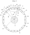
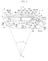
- FIG 2 is a plan view of the rotor 22, and FIG. 3 is a partially enlarged view (portion A of FIG. 2 ) of the rotor 22.
- the rotor 22 is equipped with a columnar rotor core 46 and permanent magnets 48, and is supported so as to be rotatable about an output shaft (axial center) C.
- a plurality of substantially ring-shaped magnetic plates 45 which are circular in a case where the rotor core 46 is viewed from a sight line including the axial center C, are stacked.
- openings 47 are formed, for example, at equal intervals, in the circumferential direction of yoke portions 49 in the vicinity of an outer peripheral surface 46a of the rotor core 46.
- the permanent magnets 48 are held within the openings 47, respectively.
- the rotor 22 constitutes a so-called IPM (Interior Permanent Magnet) motor in which the permanent magnets 48 are embedded in the rotor core 46.
- the permanent magnets 48 (48A, 48B) constituting a plurality of poles are arranged at predetermined polar pitch angles ⁇ (angle between centerlines P-P' of respective poles) along the circumferential direction of the rotor core 46.
- first openings 47A having the first permanent magnets 48A inserted thereinto and having a substantially rectangular shape, second openings 47B having the second permanent magnets 48B inserted thereinto and having a substantially rectangular shape, and partitions 50 partitioning the first openings 47A and the second openings 47B are formed in a region on the outer peripheral side of the rotor core 46 such that a permanent magnet 48 disposed at one pole is arranged in a segmented manner as the first permanent magnet 48A and the second permanent magnet 48B.
- each opening 47 (the first opening 47A or the second opening 55B) is orthogonal to a centerline C' passing through the central angle of the polar pitch angle ⁇ when viewed from the sight line including the axial center C of the rotor core 46.
- the centerline of the polar pitch angle ⁇ is defined as a centerline C'.
- both the shapes of the first opening 47A and the second opening 47B and the shapes of the first permanent magnet 48A and the second permanent magnet 48B are symmetrical via the partition 50. Therefore, only the shape of the first opening 47A and the shape of the first permanent magnet 48A will be described below.
- the first opening 47A is formed in a substantially rectangular shape by a first straight portion 51, a second straight portion 52, a third straight portion 53 and filling cutout portions 54, and a flux barrier 55.
- the first straight portion 51 is located at a position corresponding to a side surface of the partition 50, and is formed so as to run along the radial direction of the rotor core 46 when viewed from the sight line including the axial center C.
- the second straight portion 52 is provided to extend in a direction substantially perpendicular to the first straight portion 51 from the end portion of the partition 50 on the axial center C side (the internal diameter side of the rotor core 46), and the filling cutout portions 54 for filling an adhesive are provided at both ends of the second straight portion 52.
- the third straight portion 53 is provided to extend in a direction substantially perpendicular to the first straight portion 51 from the end portion of the partition 50 on the outer peripheral surface 46a side.
- the flux barrier 55 is formed so as to swell outward in the circumferential direction from the end portion of the second straight portion 52 and the end portion of the third straight portion 53.
- a peripheral edge portion (first circular arc) 76A of the flux barrier 55 is formed so as to have a circular arc shape, and it is preferable that the curvature radius thereof be larger in forming the flux barrier. If the rotor core 46 rotates in a state where the first permanent magnet 48A is inserted into the first opening 47A, a centrifugal force is applied to the first permanent magnet 48A.
- the stress on the external diameter side of the flux barrier 55 on which the centrifugal force is apt to act can be widely and effectively decentralized by forming the curvature radius of the first circular arc 6A to be large. Since the tensile stress of the first permanent magnet 48A caused by the centrifugal force can be widely decentralized, breakage of the rotor core 46 can be prevented and predetermined strength can be secured.
- the first permanent magnet 48A is disposed within the first opening 47A.
- the first permanent magnet 48A has a first straight portion 61 corresponding to the first straight portion 51 of the first opening 47A, a second straight portion 62 corresponding to the second straight portion 52 of the first opening 47A, a third straight portion (planar portion) 63 that faces the third straight portion 53 of the first opening 47A, and a fourth straight portion (side surface of the first opening 47A in the lateral direction) 64 that connects the end portion of the second straight portion 62 of the first opening 47A and the end portion of the third straight portion 63 and is provided to extend substantially parallel to the first straight portion 61. That is, the first permanent magnet 48A is formed, for example, in a quadrilateral shape, such as a substantially oblong shape, when viewed from the sight line including the axial center C.
- a region surrounding a circumferential center 47A 1 in an inner wall side surface (third straight portion 53) of the first opening 47A that faces the third straight portion 63 of the first permanent magnet 48A on the radial outside is located on the radial outside of the rotor core 46 with respect to both circumferential ends 47A 2 .
- the region around the center 47A 1 located closer on the radial outside than both the ends 47A 2 is defined as a relief groove 66.
- the relief groove 66 is formed over a predetermined range in the third straight portion 53.
- the permanent magnet 48 abuts against each of both the ends 47A 2 at least in two places even if a centrifugal force is generated in the permanent magnet 48 during the rotation of the rotor core 46. For this reason, the permanent magnet 48 does not abut against one place of the inner wall side surface of the first opening 47A in a concentrated manner, and a stress concentration portion can be prevented from being generated in the rotor core 46. Accordingly, the strength of the rotor core 46 can be improved. Additionally, the place where the stress of the permanent magnet 48 is applied can be arbitrarily set by adjusting the range where the relief groove 66 is provided.
- a relief groove 67 is formed over a predetermined region in the inner wall side surface (first straight portion 51) of the first opening 47A that faces the first straight portion 61 of the first permanent magnet 48A on the partition 50 side.
- the relief groove 67 is formed so that the circumferential thickness of the partition 50 can be decreased.
- the permanent magnet 48 abuts against some regions of the first straight portion 51 if a centrifugal force is generated in the permanent magnet 48 during the rotation of the rotor core 46.
- the place where the stress of the permanent magnet 48 is applied can be intentionally set by adjusting the range where the relief groove 67 is provided. Accordingly, the strength of the rotor core 46 can be improved.
- the portion of the yoke portion 49 corresponding to the polar pitch angle ⁇ of the outer peripheral surface 46a is formed in a curved manner. That is, the distance of the outer peripheral surface 46a in the yoke portion 49 from the axial center C becomes shorter when approaching both the circumferential ends of the polar pitch angle ⁇ of the outer peripheral surface 46a from an intersection 46a 1 between the centerline C' and the outer peripheral surface 46a of the rotor core 46.
- the portions of the outer peripheral surface 46a of the yoke portion 49 that are nearest to both the circumferential ends of the pitch angle are defined as both the circumferential ends 46a 2 .
- H1>H2 is satisfied if the length H1 from the axial center C to the intersection 46a 1 is compared with the length H2 from the axial center C to both the ends 46a 2 . That is, as shown in FIG 3 , the gap (gap) between the outer peripheral surface 46a and the outer peripheral surface (teeth portion) of a stator 21 becomes larger when approaching both the circumferential ends 46a 2 from an intersection 46a 1 .
- FIG. 4 The results obtained by analyzing the correlation between the size of the gap between both the circumferential ends 46a 2 of the outer peripheral surface 46a and the teeth portion of the stator 21 and the magnitude of cogging torque and torque ripple is shown in FIG. 4 .
- the cogging torque and the torque ripple decrease as the gap between both the circumferential ends 46a 2 and the teeth portion of the stator 21 is made larger. That is, the cogging torque and the torque ripple can be reduced effectively while securing the strength of the rotor core 46, by shortening the distance from the axial center C when approaching both the circumferential ends 46a 2 from the intersection 46a 1 .
- generation of noise or vibration when the rotor core 46 rotates can be suppressed.
- a region sandwiched between the first groove 70A and the second groove 70B, which are adjacent to each other, is constituted as an interpole 71.
- the interpole 71 functions as a region through which magnetic flux passes.
- the groove portion 70 (the first groove 70A or the second groove 70B) is formed to be substantially U-shaped in plan view in the immediate vicinity of the flux barrier 55, when viewed from the sight line including the axial center C.
- a groove portion formed in the vicinity of the first permanent magnet 48A is defined as the first groove 70A
- a groove portion formed in the vicinity of the second permanent magnet 48B is defined as the second groove 70B. That is, the region narrowly arranged between the first groove 70A and the second groove 70B in the rotor core 46 serves as the interpole 71.
- Convex portions 72 that protrude to both circumferential sides are respectively formed on both circumferential sides of an outer peripheral edge 71a of the interpole 71.
- the thickness W2 of the region of the outer peripheral edge 71a is formed to be greater than the thickness W1 of a region on the radial inside.
- the shape of the convex portion 72 is desirably a substantially rectangular shape when viewed from the sight line including the axial center C. As the convex portion 72 is formed in a substantially rectangular shape, the area of the convex portions 72 can be secured to be as large as possible while securing the circumferential width of the groove portion 70.
- the length from the outer peripheral surface 71b in the interpole 71 to the axial center C is almost the same along the circumferential direction of the interpole 71. That is, the gap between the outer peripheral surface 71b of the interpole 71 and the teeth portion of the stator 21 is almost equal over the total length.
- the inner peripheral surface 70a of the groove portion 70 is formed in a curved manner, and the distance between the inner peripheral surface 70a and the axial center C becomes gradually shorter when approaching the side where the interpole 71 is disposed from the centerline C'.
- the circumferential width of the interpole 71 can be secured to be large by forming the inner peripheral surface 70a of the groove portion 70 in a curved manner in this way. For this reason, improvement in the torque of the motor 23 or improvement in the strength of the rotor core 46 can be achieved.
- the circumferential width of the groove portion 70 can be made small by curvedly forming the inner peripheral surface 70a of the groove portion 70 so that the distance between the inner peripheral surface of the groove portion and the axial center C becomes gradually shorter when approaching the side where the interpole 71 is arranged from the centerline C'.
- Ribs 75 are formed between the openings 47 (the first opening 47A and the second opening 47B) and the groove portions 70 (the first groove 70A and the second groove 70B), respectively, on the yoke portion 49 of the rotor core 46.
- the ribs 75A and 75B are symmetrically formed via the permanent magnets 48, respectively. Hence, the configuration of a rib 75 will be described below taking the rib 75A as an example with reference to FIG. 5 .
- a straight portion of a side surface on the first permanent magnet 48A side among side surfaces of the rib 75A in the circumferential direction is defined as a first rib side surface 76
- a straight portion of a side surface on the interpole 71 side is defined as a second rib side surface 77.
- the first rib side surface 76 and the second rib side surface 77 are provided so as to become parallel.
- the first rib side surface 76 and the second rib side surface 77 are formed so as to incline at an angle of-45° to +45° with respect to the fourth straight portion 64 when viewed from the sight line including the axial center C.
- an example in which the first rib side surface 76 and the second rib side surface 77 are formed so as to incline at the angle of about +30° with respect to the fourth straight portion 64 is described.
- a segment along the first rib side surface 76 is defined as a first rib side surface-forming line 78
- a segment along the second rib side surface 77 is defined as a second rib side surface-forming line 79.
- a segment parallel to the first rib side surface-forming line 78 and the second rib side surface-forming line 79 and passing through an outer-peripheral-side corner portion 58 of the first permanent magnet 48A is defined as a first parallel line 80
- a segment parallel to the first rib side surface-forming line 78 and the second rib side surface-forming line 79 and passing through a deepest portion (a portion furthest toward the internal diameter side in the inner periphery of the groove portion 70) 89 of the groove portion 70 is defined as a second parallel line 81.
- the second parallel line 81 becomes a segment that coincides with the side surface 73 of the interpole 71.
- first rib side surface 76 is connected to the first circular arc 76A with a circular-arc shape.
- the first rib side surface 76 overlaps the first rib side surface-forming line 78, and an end portion of the region thereof on the axial center C side is defined as a first starting point 82, and an end portion thereof on the outer peripheral surface 46a is defined as the first ending point 83.
- the second rib side surface 77 is connected to the second circular arc 77A with a circular-arc shape.
- the second rib side surface 77 overlaps the second rib side surface-forming line 79, and an end portion of the region thereof on the axial center C side is defined as a second starting point 85, and an end portion thereof on the outer peripheral surface 46a is defined as the second ending point 86.
- a second starting point 85 is located closer to the outer peripheral surface 46a side than the first perpendicular line 88.
- the deepest portion 89 of the side surface 73 of the interpole 71 is located closer to the outer peripheral surface 46a side than the first perpendicular line 88 and is located closer to the axial center C side than the second starting point 85.
- the first ending point 83 is located closer to the axial center C side than the second perpendicular line 90.
- the outer-peripheral-side corner portion 58 of the first permanent magnet 48A is located closer to the axial center C side than the second perpendicular line 90 and closer to the outer peripheral surface 46a than the first ending point 83.
- the first ending point 83 and the outer-peripheral-side corner portion 58 of the first permanent magnet 48A are connected by, for example, the first circular arc 76A with a circular-arc shape.
- the second starting point 85 and the deepest portions 89 are also connected by, for example, the second circular arc 77A with a circular-arc shape.
- the shape of the first circular arc 76A and the second circular arc 77A is not limited to the circular-arc shape, and may be a straight shape.
- the rib 75 is formed with a stress-absorbing portion 94 made from a thin-walled portion with a smallest thickness in the yoke portion 49. If segments parallel to the first perpendicular line 88 and intersecting the first rib side surface 76 and the second rib side surface 77 are defined as a third perpendicular line 91 and a fourth perpendicular line 92, respectively, the stress-absorbing portion 94 becomes a region surrounded by the first rib side surface 76, the second rib side surface 77, the third perpendicular line 91, and the fourth perpendicular line 92.
- the distance D1 between the second circular arc 77A and the outer peripheral surface 71b is set to a depth such that the short-circuiting magnetic flux between respective adjacent poles can be reduced.
- the distance X1 when the axial center C and the deepest portion 89 are connected to each other is shorter than the distance X2 between the outer-peripheral-side corner portion 58 of the permanent magnet 48 near the deepest portion 89 and the axial center C. That is, the position of the deepest portion 89 is set so that the groove portion 70 and the permanent magnet 48 overlap each other in the circumferential direction.
- the circumferential width of the groove portion 70 is not particularly limited, it is desirable to set the width to a length such that the strength of the rotor core 46 is secured. Additionally, it is preferable for the performance of the motor 23 that the formation position of the groove portion 70 be a position closer to the permanent magnet 48 near the groove portion 70. However, as shown in FIG. 5 , the circumferential width W3 of the stress-absorbing portion 94 becomes smaller as the formation position of the groove portion 70 becomes closer to the permanent magnet 48. For this reason, it is required to set the circumferential width W3 of the circumferential of the stress-absorbing portion 94 and the formation position of the groove portion 70 in consideration of the strength of the rotor core 46.
- the stress-absorbing portion 94 in the rotor core 46 becomes a portion where magnetic flux is saturated most, occurrence of magnetic flux short-circuiting can be prevented by the flux barrier 55 being formed on one side of the stress-absorbing portion 94 and the groove portion 70 being formed on the other side.
- the stress generated in the rotor 22 due to the permanent magnet 48 concentrates on the stress-absorbing portion 94 by providing the rib 75 (75A, 75B) with the stress-absorbing portion 94 made from a thin-walled portion with a smallest thickness in the yoke portion 49 in a cross-sectional view of a cross-section including the axial center C of the rotor 22. For this reason, the stress generated in the rotor 22 can be absorbed by the stress-absorbing portion 94.
- the stress can be prevented from concentrating on the root of the rib 75. For this reason, it is unnecessary to secure the thickness of the root portion of the rib 75, the degree of freedom in the design of the rotor core 46 can be improved, and reduction in the weight of the rotor 22 can be realized.
- the longitudinal axis L of the opening 47 is formed so as to be orthogonal to the centerline C' when viewed from the sight line including the axial center C of the rotor core 46, the stress of the permanent magnet 48 caused by the rotation of the rotor core 46 can be concentrated on the rib 75.
- the side surfaces of the rib 75 in the circumferential direction are formed with the first rib side surface 76, the first circular arc 76A connected to the first rib side surface 76, the second rib side surface 77, and the second circular arc 77A connected to the interpole 71 from the second rib side surface 77, the stress concentrated on the rib 75 can be efficiently absorbed by the stress-absorbing portion 94 provided between the first rib side surface 76 and the second rib side surface 77. Additionally, the tensile stress that acts on the peripheral edge portion of the flux barrier 55 due to the rotation of the rotor core 46 can be widely and effectively decentralized in the first circular arc 76A. For this reason, damage of the rotor core 46 caused by the tensile stress can be prevented, and predetermined strength can be secured.
- the portion does not easily protrude radially outward more than the outermost peripheral surface 46a side of the rotor 22. For this reason, the interference between the stator 21 and the rotor 22 can be reliably prevented. Additionally, the gap between the stator 21 and the rotor 22 can be made smaller.
- the permanent magnet 48 abuts against each of both the ends 47A 2 at least in two places even if a centrifugal force is generated in the permanent magnet 48 during the rotation of the rotor core 46. For this reason, the permanent magnet 48 does not abut against one place of the inner wall side surface of the first opening 47A in a concentrated manner, and a stress concentration portion can be prevented from being generated in the rotor core 46. Additionally, the place where the stress of the permanent magnet 48 is applied can be intentionally set by adjusting the range where the relief groove 66 is provided. Accordingly, the strength of the rotor core 46 can be improved.
- the torque ripple can be reduced while generating the reluctance torque, by adopting the motor 23 having the rotor 22 configured as described above.
- the motor 23 that can raise the torque can be provided from the above.
- the present invention is not limited to the above-described embodiment, but that various modifications of the above-described embodiment may be made without departing from the scope of the invention. That is, the specific structures and shapes as set forth in the embodiment are no more than examples and can be appropriately changed. For example, although a case where the partition 50 is provided at the rotor core 46 to split the permanent magnet 48 so as to be disposed as the first permanent magnet 48A and the second permanent magnet 48B has been described in the present embodiment, the permanent magnet 48 may not be split. Additionally, in the present embodiment, the filling cutout portions 54 for being filled with an adhesive are formed in the opening 47.
- the filling cutout portions 54 may not be formed.
- any kind of filler material may be used as long as the permanent magnet 48 is held within the opening 47.
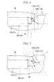
- the side surfaces of a rib 175A in the circumferential direction may be formed so as to be substantially parallel (an angle of about 0° with respect to the fourth straight portion 64) to the fourth straight portion 64.
- the side surfaces of a rib 275A in the circumferential direction may be formed so as to incline at an angle of about -30° with respect to the fourth straight portion 64. That is, the side surfaces of the first rib in the circumferential direction may be formed so as to incline at an angle of -45° to +45° with respect to the fourth straight portion 64.
- a rotor and a motor capable of suppressing stress concentration on the root of a rib can be provided.
Landscapes
- Engineering & Computer Science (AREA)
- Power Engineering (AREA)
- Permanent Field Magnets Of Synchronous Machinery (AREA)
- Iron Core Of Rotating Electric Machines (AREA)
Abstract
Description
- The present invention relates to a rotor and a motor.
Priority is claimed on Japanese Patent Application No.2010-172260, filed July 30,2010 - In the related art, motors are known including a rotor that is rotatably supported around an axial center and has permanent magnets disposed therearound, and a stator that is arranged around the rotor to face the rotor and has coils wound therearound. In such motors, a motor that achieves high torque and high efficiency is proposed (for example, refer to Patent Document 1).
- For example, in the permanent magnet motor (motor) of Patent Document 1, the rotor (rotor) is arranged inside the stator that generates a rotating magnetic field. In the vicinity of a d-axis of this rotor, a plurality of first permanent magnets with a rectangular cross-section is buried at equal intervals in the circumferential direction. Moreover, in the vicinity of a q-axis, a plurality of second prismatic permanent magnets is arranged at equal intervals in the circumferential direction. The main poles are formed by these first and second permanent magnets, and the paths (magnetic paths) of magnetic flux from one q-axis to another q-axis are secured between the first permanent magnets and the second permanent magnets. Additionally, interpoles are formed at the rotor and flux barriers are formed on both end sides of the first permanent magnets.
- [Patent Document 1] Japanese Unexamined Patent Application, First Publication No.
2000-333390 - Incidentally, in the rotor of Patent Document 1 described above, the flux barriers in which cutout portions (interpole-forming grooves) are formed in the peripheral edge portion of the rotor core are proposed. When such a rotor rotates about the axial center, a centrifugal force is generated in the permanent magnets. As a result, stress concentrates on the root (radial outside end portion of a rib) of a rib formed between the permanent magnets and the interpole-forming grooves. Accordingly, such a rotor strengthens the root portion of the rib, and it is necessary to prevent the rotor core from being bent. For this reason, the rotor of the related art has a problem in that design should be made so that the thickness of the root portion of the rib can be secured.
- Thus, an object of the invention is to provide a rotor and a motor capable of suppressing stress concentration on the root of a rib.
- In order to solve the above problem, respective aspects of the invention adopt the following means.
[1] A rotor related to one aspect of the invention is a rotor including a columnar rotor core; and permanent magnets arranged side by side along a predetermined polar pitch angle in the circumferential direction of the rotor core when viewed from a sight line including an axial center of the rotor core. The rotor core is formed with openings formed in the outer peripheral surface of the rotor core and having the permanent magnets inserted thereinto; interpole-forming grooves formed by a pair of first and second grooves that each extend in the direction of the axial center on both circumferential sides of the openings, and formed in the same number as the number of magnetic poles; an interpole formed between the first groove and the second groove adjacent to the first groove; and a rib formed between the opening and the interpole-forming groove, in a yoke portion of the rotor core. The rib is formed with a stress-absorbing portion made from a thin-walled portion with a smallest thickness in the yoke portion in a cross-sectional view of a cross-section including the axial center of the rotor. - [2] In the rotor described in the above [1], a longitudinal axis of the opening may be formed so as to be orthogonal to a centerline passing through the central angle of the polar pitch angle when viewed from the sight line including the axial center of the rotor core; the side surfaces of the rib may have a first rib side surface on the side of the permanent magnet, a first circular arc connected to the opening from the first rib side surface, a second rib side surface on the interpole side, and a second circular arc connected to the interpole from the second rib side surface; and the stress-absorbing portion may be provided between the first rib side surface and the second rib side surface.
- [3] In the rotor described in the above [1], when viewed from the sight line including the axial center of the rotor core, the distance of the yoke portion from the axial center may become shorter when approaching both circumferential ends of the polar pitch angle from an intersection between the centerline passing through the central angle of the polar pitch angle and the outer peripheral surface of the rotor core.
- [4] In the rotor described in the above [1], a circumferential center of an inner wall side surface of the opening that faces a planar portion on the radial outside of the permanent magnet may be located on the radial outside of the rotor core with respect to both circumferential ends of the inner wall side surface.
- [5] A motor related to one aspect of the invention is a motor including the rotor described in any one of the above [1] to [4]; a cylindrical stator disposed so as to surround the rotor; and a winding wire wound around a teeth portion of the stator.
- According to the rotor related to the aspect of the above [1], if the rotor core rotates around the axial center in a state where the permanent magnet is inserted into the opening, a centrifugal force is generated in the permanent magnet. In this case, the stress of the permanent magnet concentrates on the stress-absorbing portion of the rib. Since this stress-absorbing portion is made from the thin-walled portion with a smallest thickness in the yoke portion in a cross-sectional view of a cross-section including the axial center of the rotor, the stress-absorbing portion can efficiently absorb the stress generated in the rotor. For this reason, the stress concentration to the root of the rib can be suppressed. From the above, it is unnecessary to secure the thickness of the root portion of the rib, and reduction in the weight of the rotor can be realized.
- According to the rotor related to the aspect of the above [2], since the longitudinal axis of the opening is formed so as to be orthogonal to the centerline of the polar pitch angle when viewed from the sight line including the axial center of the rotor core, the stress of the permanent magnet caused by the rotation of the rotor core can be concentrated on the rib. Additionally, since the side surfaces of the rib have the first rib side surface on the permanent magnet side, the first circular arc connected to the first rib side surface, the second rib side surface on the interpole side, and the second circular arc connected to the interpole from the second rib side surface, the stress caused by the rotation of the rotor core can be concentrated between the first rib side surface and the second rib side surface. From the above, the stress caused by the rotation of the rotor core can be efficiently absorbed by the stress-absorbing portion provided between the first rib side surface and the second rib side surface.
- According to the rotor related to the aspect of the above [3], the distance from the axial center becomes shorter when approaching both the circumferential ends of the polar pitch angle from the intersection between the centerline passing through the central angle of the polar pitch angle and the outer peripheral surface of the rotor core. For this reason, the distance between the outer peripheral surface of the rotor core and the outer peripheral surface of the stator becomes larger when approaching both the circumferential ends of the polar pitch angle, and torque ripple and cogging torque caused by the rotation of the rotor core can be reduced. As a result, vibration or noise can be suppressed during motor driving when the rotor core rotates.
Additionally, at both the circumferential ends of the polar pitch angle, there is the distance between the outer peripheral surface of the rotor core and the outer peripheral surface of the stator. For this reason, even if the rib stretches by the stress caused by the rotation of the rotor core being absorbed by the stress-absorbing portion, the portion where the rib has stretched does not easily protrude radially outward more than the outermost peripheral surface of the rotor. Therefore, the interference between the stator and the rotor can be reliably prevented. Additionally, the gap between the stator and the rotor can be made smaller. - According to the rotor related to the aspect of the above [4], if a centrifugal force is generated in the permanent magnet during rotor rotation, the permanent magnet abuts against at least two places of both the circumferential ends of the inner wall side surface of the opening. For this reason, the permanent magnet does not abut against one place of the inner wall side surface of the opening in a concentrated manner, and a stress concentration portion can be prevented from being generated in the rotor core. Accordingly, the strength of the rotor core can be improved.
- According to the motor related to the aspect of the above [5], the stress resulting from the centrifugal force generated in the permanent magnet during rotor rotation can be absorbed in the stress-absorbing portion by the stress-absorbing portion being formed at the rib. As a result, the stress concentration to the root of the rib can be suppressed. For this reason, it is unnecessary to secure the thickness of the root portion of the rib, the degree of freedom in the design of the rotor core can be improved, and reduction in the weight of the rotor core can be realized. Additionally, the torque ripple can be reduced while generating reluctance torque by the interpole being formed at the rotor core. From the above, a motor that can improve torque can be provided.
-
-
FIG. 1 is a schematic cross-sectional view of the configuration of a motor unit in one embodiment of the invention. -
FIG. 2 is a plan view of a rotor in this embodiment. -
FIG. 3 is a partially enlarged view of the rotor. -
FIG. 4 is a graph showing changes in cogging torque and torque ripple when a gap is provided at the outer peripheral surface of a rotor core in this embodiment. -
FIG. 5 is a view in which segments required to illustrate the shape of a rib are described in a partially enlarged view ofFIG. 3 . -
FIG. 6 is a view (corresponding toFIG. 3 ) showing the shape of another aspect of an interpole-forming groove in one embodiment of the invention. -
FIG. 7 is a view (corresponding toFIG. 3 ) showing the shape of still another aspect of the interpole-forming groove in one embodiment of the invention. - Next, a motor related to one embodiment of the invention will be described with reference to
FIGS. 1 to 7 . In addition, a motor used as a motor unit for a vehicle is described in the present embodiment.
FIG. 1 is a schematic cross-sectional view of the configuration of the motor unit for a vehicle. As shown inFIG 1 , amotor unit 10 for a vehicle (hereinafter referred to as motor unit) is provided with amotor 23. Themotor 23 is equipped with arotor 22. Acylindrical stator 21 around which winding wires (coils) 20 are wound andpermanent magnets 48 are disposed in therotor 22. Additionally, therotor 22 is arranged to face thestator 21 at a predetermined interval therefrom.
Moreover, themotor unit 10 is equipped with amotor housing 11, atransmission housing 12, and asensor housing 13. Themotor 23 is accommodated in themotor housing 11. Additionally, thetransmission housing 12 is fastened to one side of themotor housing 11, and a power transmission part (not shown) is accommodated in thetransmission housing 12. The power generated from anoutput shaft 24 of themotor 23 is transmitted to this power transmission part. Thesensor housing 13 is fastened to the other side of themotor housing 11, and arotation sensor 25 of themotor 23 is accommodated in thesensor housing 13. In addition, the inside of themotor housing 11 is constituted as amotor chamber 36, the inside of thetransmission housing 12 is constituted as atransmission chamber 37, and, the inside of thesensor housing 13, is constituted as asensor chamber 38. - The
motor housing 11 is formed in a substantially cylindrical shape that covers thewhole motor 23. A bearing 26 that rotatably supports one end of theoutput shaft 24 of themotor 23 is provided on thetransmission housing 12 side of a boundary portion between themotor housing 11 and thetransmission housing 12. A bearing 27 that rotatably supports the other end of theoutput shaft 24 of themotor 23 is provided on thesensor housing 13 side of a boundary portion between themotor housing 11 and thesensor housing 13. -
Breather passages 35 that communicate with each other are respectively formed in awall portion 31 of themotor housing 11, awall portion 32 of thetransmission housing 12, and awall portion 33 of thesensor housing 13.
Moreover, awater jacket 40 for cooling themotor 23 is provided within thewall portion 31 of themotor housing 11 so as to cover the whole circumference of thestator 21 of themotor 23. Additionally, thestator 21 is press-fitted into themotor housing 11, and is disposed so as to come into close contact with the inner peripheral surface of themotor housing 11. - A
breather chamber 42 for separating lubrication oil that is being used within themotor unit 10 is formed within thetransmission housing 12. Thereby, the lubrication oil scattered by the rotation of the power transmission part (gear) or themotor 23 is separated by thebreather chamber 42, and can be prevented from leaking from breather piping 39 to the outside. - The
breather chamber 42 is formed at a position corresponding to a topmost part of themotor unit 10. Additionally, thebreather chamber 42 communicates with thebreather passages 35 so that the high-pressure and high-temperature air within themotor unit 10 can be discharged from the breather piping 39. Moreover, thebreather chamber 42 communicates with themotor chamber 36, thetransmission chamber 37, and thesensor chamber 38 via thebreather passages 35. - Here, the configuration of the
rotor 22 of themotor unit 10 will be described below in detail with reference toFIGS. 2 and3 .FIG 2 is a plan view of therotor 22, andFIG. 3 is a partially enlarged view (portion A ofFIG. 2 ) of therotor 22.
As shown inFIG. 2 , therotor 22 is equipped with acolumnar rotor core 46 andpermanent magnets 48, and is supported so as to be rotatable about an output shaft (axial center) C. A plurality of substantially ring-shapedmagnetic plates 45, which are circular in a case where therotor core 46 is viewed from a sight line including the axial center C, are stacked. Moreover,openings 47 are formed, for example, at equal intervals, in the circumferential direction ofyoke portions 49 in the vicinity of an outerperipheral surface 46a of therotor core 46.
Thepermanent magnets 48 are held within theopenings 47, respectively. Therotor 22 constitutes a so-called IPM (Interior Permanent Magnet) motor in which thepermanent magnets 48 are embedded in therotor core 46. - As shown in
FIG. 3 , in a case where therotor core 46 of the present embodiment is viewed from the sight line including the axial center C of therotor core 46, the permanent magnets 48 (48A, 48B) constituting a plurality of poles are arranged at predetermined polar pitch angles α (angle between centerlines P-P' of respective poles) along the circumferential direction of therotor core 46.
Additionally,first openings 47A having the firstpermanent magnets 48A inserted thereinto and having a substantially rectangular shape,second openings 47B having the secondpermanent magnets 48B inserted thereinto and having a substantially rectangular shape, andpartitions 50 partitioning thefirst openings 47A and thesecond openings 47B are formed in a region on the outer peripheral side of therotor core 46 such that apermanent magnet 48 disposed at one pole is arranged in a segmented manner as the firstpermanent magnet 48A and the secondpermanent magnet 48B. Also, a longitudinal axis L of each opening 47 (thefirst opening 47A or the second opening 55B) is orthogonal to a centerline C' passing through the central angle of the polar pitch angle α when viewed from the sight line including the axial center C of therotor core 46. In addition, in the following description, the centerline of the polar pitch angle α is defined as a centerline C'. - In the following description, the shapes of the
opening 47 and thepermanent magnets 48 will be described. However, both the shapes of thefirst opening 47A and thesecond opening 47B and the shapes of the firstpermanent magnet 48A and the secondpermanent magnet 48B are symmetrical via thepartition 50. Therefore, only the shape of thefirst opening 47A and the shape of the firstpermanent magnet 48A will be described below. - The
first opening 47A is formed in a substantially rectangular shape by a firststraight portion 51, a secondstraight portion 52, a thirdstraight portion 53 and fillingcutout portions 54, and aflux barrier 55.
Among these, the firststraight portion 51 is located at a position corresponding to a side surface of thepartition 50, and is formed so as to run along the radial direction of therotor core 46 when viewed from the sight line including the axial center C. The secondstraight portion 52 is provided to extend in a direction substantially perpendicular to the firststraight portion 51 from the end portion of thepartition 50 on the axial center C side (the internal diameter side of the rotor core 46), and the fillingcutout portions 54 for filling an adhesive are provided at both ends of the secondstraight portion 52. The thirdstraight portion 53 is provided to extend in a direction substantially perpendicular to the firststraight portion 51 from the end portion of thepartition 50 on the outerperipheral surface 46a side. Also, theflux barrier 55 is formed so as to swell outward in the circumferential direction from the end portion of the secondstraight portion 52 and the end portion of the thirdstraight portion 53. In addition, a peripheral edge portion (first circular arc) 76A of theflux barrier 55 is formed so as to have a circular arc shape, and it is preferable that the curvature radius thereof be larger in forming the flux barrier.
If therotor core 46 rotates in a state where the firstpermanent magnet 48A is inserted into thefirst opening 47A, a centrifugal force is applied to the firstpermanent magnet 48A. Thereby, although a tensile stress acts on the firstcircular arc 76A, in particular, the stress on the external diameter side of theflux barrier 55 on which the centrifugal force is apt to act can be widely and effectively decentralized by forming the curvature radius of the first circular arc 6A to be large. Since the tensile stress of the firstpermanent magnet 48A caused by the centrifugal force can be widely decentralized, breakage of therotor core 46 can be prevented and predetermined strength can be secured. - The first
permanent magnet 48A is disposed within thefirst opening 47A. The firstpermanent magnet 48A has a firststraight portion 61 corresponding to the firststraight portion 51 of thefirst opening 47A, a secondstraight portion 62 corresponding to the secondstraight portion 52 of thefirst opening 47A, a third straight portion (planar portion) 63 that faces the thirdstraight portion 53 of thefirst opening 47A, and a fourth straight portion (side surface of thefirst opening 47A in the lateral direction) 64 that connects the end portion of the secondstraight portion 62 of thefirst opening 47A and the end portion of the thirdstraight portion 63 and is provided to extend substantially parallel to the firststraight portion 61. That is, the firstpermanent magnet 48A is formed, for example, in a quadrilateral shape, such as a substantially oblong shape, when viewed from the sight line including the axial center C. - Moreover, a region surrounding a
circumferential center 47A1 in an inner wall side surface (third straight portion 53) of thefirst opening 47A that faces the thirdstraight portion 63 of the firstpermanent magnet 48A on the radial outside is located on the radial outside of therotor core 46 with respect to both circumferential ends 47A2. The region around thecenter 47A1 located closer on the radial outside than both theends 47A2 is defined as arelief groove 66.
Therelief groove 66 is formed over a predetermined range in the thirdstraight portion 53. As therelief groove 66 is formed in the thirdstraight portion 53 in this way, thepermanent magnet 48 abuts against each of both theends 47A2 at least in two places even if a centrifugal force is generated in thepermanent magnet 48 during the rotation of therotor core 46. For this reason, thepermanent magnet 48 does not abut against one place of the inner wall side surface of thefirst opening 47A in a concentrated manner, and a stress concentration portion can be prevented from being generated in therotor core 46. Accordingly, the strength of therotor core 46 can be improved. Additionally, the place where the stress of thepermanent magnet 48 is applied can be arbitrarily set by adjusting the range where therelief groove 66 is provided. - Additionally, a
relief groove 67 is formed over a predetermined region in the inner wall side surface (first straight portion 51) of thefirst opening 47A that faces the firststraight portion 61 of the firstpermanent magnet 48A on thepartition 50 side. Therelief groove 67 is formed so that the circumferential thickness of thepartition 50 can be decreased. As therelief groove 67 is formed in this way, thepermanent magnet 48 abuts against some regions of the firststraight portion 51 if a centrifugal force is generated in thepermanent magnet 48 during the rotation of therotor core 46. For this reason, the place where the stress of thepermanent magnet 48 is applied can be intentionally set by adjusting the range where therelief groove 67 is provided. Accordingly, the strength of therotor core 46 can be improved. - Additionally, as shown in
FIG. 3 , when therotor core 46 is viewed from the sight line including the axial center C, the portion of theyoke portion 49 corresponding to the polar pitch angle α of the outerperipheral surface 46a is formed in a curved manner. That is, the distance of the outerperipheral surface 46a in theyoke portion 49 from the axial center C becomes shorter when approaching both the circumferential ends of the polar pitch angle α of the outerperipheral surface 46a from anintersection 46a1 between the centerline C' and the outerperipheral surface 46a of therotor core 46. Hereinafter, the portions of the outerperipheral surface 46a of theyoke portion 49 that are nearest to both the circumferential ends of the pitch angle are defined as both the circumferential ends 46a2.
To describe specifically, as shown inFIG. 2 , H1>H2 is satisfied if the length H1 from the axial center C to theintersection 46a1 is compared with the length H2 from the axial center C to both theends 46a2. That is, as shown inFIG 3 , the gap (gap) between the outerperipheral surface 46a and the outer peripheral surface (teeth portion) of astator 21 becomes larger when approaching both the circumferential ends 46a2 from anintersection 46a1. - The results obtained by analyzing the correlation between the size of the gap between both the circumferential ends 46a2 of the outer
peripheral surface 46a and the teeth portion of thestator 21 and the magnitude of cogging torque and torque ripple is shown inFIG. 4 . As shown inFIG. 4 , it turns out that the cogging torque and the torque ripple decrease as the gap between both the circumferential ends 46a2 and the teeth portion of thestator 21 is made larger. That is, the cogging torque and the torque ripple can be reduced effectively while securing the strength of therotor core 46, by shortening the distance from the axial center C when approaching both the circumferential ends 46a2 from theintersection 46a1. As a result, generation of noise or vibration when therotor core 46 rotates can be suppressed. - Referring back to
FIG 3 , a set of groove portions (interpole-forming grooves) 70 including afirst groove 70A and asecond groove 70B, which extends in the direction of the axial center C from the outerperipheral surface 46a, are formed on both circumferential sides of theopenings 47 between adjacent poles in therotor core 46. That is, the same number of interpole-forminggrooves 70 as magnetic poles are formed. As shown inFIG. 3 , a region sandwiched between thefirst groove 70A and thesecond groove 70B, which are adjacent to each other, is constituted as aninterpole 71. Theinterpole 71 functions as a region through which magnetic flux passes. - The groove portion 70 (the
first groove 70A or thesecond groove 70B) is formed to be substantially U-shaped in plan view in the immediate vicinity of theflux barrier 55, when viewed from the sight line including the axial center C. Here, a groove portion formed in the vicinity of the firstpermanent magnet 48A is defined as thefirst groove 70A and a groove portion formed in the vicinity of the secondpermanent magnet 48B is defined as thesecond groove 70B. That is, the region narrowly arranged between thefirst groove 70A and thesecond groove 70B in therotor core 46 serves as theinterpole 71. -
Convex portions 72 that protrude to both circumferential sides are respectively formed on both circumferential sides of an outerperipheral edge 71a of theinterpole 71. As for the circumferential thickness of theinterpole 71, the thickness W2 of the region of the outerperipheral edge 71a is formed to be greater than the thickness W1 of a region on the radial inside. The shape of theconvex portion 72 is desirably a substantially rectangular shape when viewed from the sight line including the axial center C. As theconvex portion 72 is formed in a substantially rectangular shape, the area of theconvex portions 72 can be secured to be as large as possible while securing the circumferential width of thegroove portion 70.
Additionally, the length from the outerperipheral surface 71b in theinterpole 71 to the axial center C is almost the same along the circumferential direction of theinterpole 71. That is, the gap between the outerperipheral surface 71b of theinterpole 71 and the teeth portion of thestator 21 is almost equal over the total length. - Moreover, the inner
peripheral surface 70a of thegroove portion 70 is formed in a curved manner, and the distance between the innerperipheral surface 70a and the axial center C becomes gradually shorter when approaching the side where theinterpole 71 is disposed from the centerline C'. The circumferential width of theinterpole 71 can be secured to be large by forming the innerperipheral surface 70a of thegroove portion 70 in a curved manner in this way. For this reason, improvement in the torque of themotor 23 or improvement in the strength of therotor core 46 can be achieved. In addition, in a case where the innerperipheral surface 70a is formed in a curved manner as described above and in a case where the inner peripheral surface is formed so as to be U-shaped, stress distribution does not change even in a case where the centrifugal force of thepermanent magnet 48 is generated due to the rotation of therotor 22. That is, even in a case where the shape of the innerperipheral surface 70a is any one of the above shapes, stress is generated on the centerline C' side of the innerperipheral surface 70a, but stress is not generated on theinterpole 71 side. Accordingly, the circumferential width of thegroove portion 70 can be made small by curvedly forming the innerperipheral surface 70a of thegroove portion 70 so that the distance between the inner peripheral surface of the groove portion and the axial center C becomes gradually shorter when approaching the side where theinterpole 71 is arranged from the centerline C'. - Ribs 75 (a
rib 75A and arib 75B) are formed between the openings 47 (thefirst opening 47A and thesecond opening 47B) and the groove portions 70 (thefirst groove 70A and thesecond groove 70B), respectively, on theyoke portion 49 of therotor core 46. Theribs permanent magnets 48, respectively. Hence, the configuration of arib 75 will be described below taking therib 75A as an example with reference toFIG. 5 . - A straight portion of a side surface on the first
permanent magnet 48A side among side surfaces of therib 75A in the circumferential direction is defined as a firstrib side surface 76, and a straight portion of a side surface on theinterpole 71 side is defined as a secondrib side surface 77. The firstrib side surface 76 and the secondrib side surface 77 are provided so as to become parallel. Additionally, the firstrib side surface 76 and the secondrib side surface 77 are formed so as to incline at an angle of-45° to +45° with respect to the fourthstraight portion 64 when viewed from the sight line including the axial center C. In the present embodiment, an example in which the firstrib side surface 76 and the secondrib side surface 77 are formed so as to incline at the angle of about +30° with respect to the fourthstraight portion 64 is described. - Here, as shown in
FIG. 5 , a segment along the firstrib side surface 76 is defined as a first rib side surface-formingline 78, and a segment along the secondrib side surface 77 is defined as a second rib side surface-formingline 79. A segment parallel to the first rib side surface-formingline 78 and the second rib side surface-formingline 79 and passing through an outer-peripheral-side corner portion 58 of the firstpermanent magnet 48A is defined as a firstparallel line 80, and a segment parallel to the first rib side surface-formingline 78 and the second rib side surface-formingline 79 and passing through a deepest portion (a portion furthest toward the internal diameter side in the inner periphery of the groove portion 70) 89 of thegroove portion 70 is defined as a secondparallel line 81. In addition, in the present embodiment, the secondparallel line 81 becomes a segment that coincides with theside surface 73 of theinterpole 71. - Additionally, the first
rib side surface 76 is connected to the firstcircular arc 76A with a circular-arc shape. The firstrib side surface 76 overlaps the first rib side surface-formingline 78, and an end portion of the region thereof on the axial center C side is defined as afirst starting point 82, and an end portion thereof on the outerperipheral surface 46a is defined as thefirst ending point 83.
Additionally, the secondrib side surface 77 is connected to the secondcircular arc 77A with a circular-arc shape. The secondrib side surface 77 overlaps the second rib side surface-formingline 79, and an end portion of the region thereof on the axial center C side is defined as asecond starting point 85, and an end portion thereof on the outerperipheral surface 46a is defined as thesecond ending point 86. - In the present embodiment, in a case where a segment orthogonal to the first rib side surface-forming
line 78 and passing through thefirst starting point 82 is defined as a firstperpendicular line 88, asecond starting point 85 is located closer to the outerperipheral surface 46a side than the firstperpendicular line 88. Additionally, thedeepest portion 89 of theside surface 73 of theinterpole 71 is located closer to the outerperipheral surface 46a side than the firstperpendicular line 88 and is located closer to the axial center C side than thesecond starting point 85.
Moreover, in a case where a segment orthogonal to the second rib side surface-formingline 79 and passing through thesecond ending point 86 is defined as a secondperpendicular line 90, thefirst ending point 83 is located closer to the axial center C side than the secondperpendicular line 90. Also, the outer-peripheral-side corner portion 58 of the firstpermanent magnet 48A is located closer to the axial center C side than the secondperpendicular line 90 and closer to the outerperipheral surface 46a than thefirst ending point 83. - In the present embodiment, the
first ending point 83 and the outer-peripheral-side corner portion 58 of the firstpermanent magnet 48A are connected by, for example, the firstcircular arc 76A with a circular-arc shape. Also, thesecond starting point 85 and thedeepest portions 89 are also connected by, for example, the secondcircular arc 77A with a circular-arc shape. In addition, the shape of the firstcircular arc 76A and the secondcircular arc 77A is not limited to the circular-arc shape, and may be a straight shape. - In a cross-sectional view of a cross-section including the axial center C of the
rotor 22, therib 75 is formed with a stress-absorbingportion 94 made from a thin-walled portion with a smallest thickness in theyoke portion 49. If segments parallel to the firstperpendicular line 88 and intersecting the firstrib side surface 76 and the secondrib side surface 77 are defined as a thirdperpendicular line 91 and a fourthperpendicular line 92, respectively, the stress-absorbingportion 94 becomes a region surrounded by the firstrib side surface 76, the secondrib side surface 77, the thirdperpendicular line 91, and the fourthperpendicular line 92. - Additionally, the distance D1 between the second
circular arc 77A and the outerperipheral surface 71b is set to a depth such that the short-circuiting magnetic flux between respective adjacent poles can be reduced. Specifically, as shown inFIG. 2 , the distance X1 when the axial center C and thedeepest portion 89 are connected to each other is shorter than the distance X2 between the outer-peripheral-side corner portion 58 of thepermanent magnet 48 near thedeepest portion 89 and the axial center C. That is, the position of thedeepest portion 89 is set so that thegroove portion 70 and thepermanent magnet 48 overlap each other in the circumferential direction. - In addition, although the circumferential width of the
groove portion 70 is not particularly limited, it is desirable to set the width to a length such that the strength of therotor core 46 is secured. Additionally, it is preferable for the performance of themotor 23 that the formation position of thegroove portion 70 be a position closer to thepermanent magnet 48 near thegroove portion 70. However, as shown inFIG. 5 , the circumferential width W3 of the stress-absorbingportion 94 becomes smaller as the formation position of thegroove portion 70 becomes closer to thepermanent magnet 48. For this reason, it is required to set the circumferential width W3 of the circumferential of the stress-absorbingportion 94 and the formation position of thegroove portion 70 in consideration of the strength of therotor core 46. Additionally, although the stress-absorbingportion 94 in therotor core 46 becomes a portion where magnetic flux is saturated most, occurrence of magnetic flux short-circuiting can be prevented by theflux barrier 55 being formed on one side of the stress-absorbingportion 94 and thegroove portion 70 being formed on the other side. - According to the present embodiment, if the
rotor core 46 rotates around the axial center C in a state where thepermanent magnet 48 is inserted into theopening 47, a centrifugal force is generated in thepermanent magnet 48. In this case, the stress generated in therotor 22 due to thepermanent magnet 48 concentrates on the stress-absorbingportion 94 by providing the rib 75 (75A, 75B) with the stress-absorbingportion 94 made from a thin-walled portion with a smallest thickness in theyoke portion 49 in a cross-sectional view of a cross-section including the axial center C of therotor 22. For this reason, the stress generated in therotor 22 can be absorbed by the stress-absorbingportion 94. As a result, the stress can be prevented from concentrating on the root of therib 75. For this reason, it is unnecessary to secure the thickness of the root portion of therib 75, the degree of freedom in the design of therotor core 46 can be improved, and reduction in the weight of therotor 22 can be realized. - Since the longitudinal axis L of the
opening 47 is formed so as to be orthogonal to the centerline C' when viewed from the sight line including the axial center C of therotor core 46, the stress of thepermanent magnet 48 caused by the rotation of therotor core 46 can be concentrated on therib 75.
Additionally, since the side surfaces of therib 75 in the circumferential direction are formed with the firstrib side surface 76, the firstcircular arc 76A connected to the firstrib side surface 76, the secondrib side surface 77, and the secondcircular arc 77A connected to theinterpole 71 from the secondrib side surface 77, the stress concentrated on therib 75 can be efficiently absorbed by the stress-absorbingportion 94 provided between the firstrib side surface 76 and the secondrib side surface 77. Additionally, the tensile stress that acts on the peripheral edge portion of theflux barrier 55 due to the rotation of therotor core 46 can be widely and effectively decentralized in the firstcircular arc 76A. For this reason, damage of therotor core 46 caused by the tensile stress can be prevented, and predetermined strength can be secured. - That is, since the distance from the axial center C becomes shorter when approaching both the circumferential ends of the polar pitch angle α of the outer
peripheral surface 46a from theintersection 46a1 between the centerline C' and the outerperipheral surface 46a of therotor core 46, the distance between the outerperipheral surface 46a of therotor core 46 and the teeth portion (outer peripheral surface) of thestator 21 becomes larger when approaching both the circumferential ends 46a2. This can reduce the torque ripple and the cogging torque caused by the rotation of therotor core 46. As a result, vibration or noise can be prevented from being generated during motor driving when therotor core 46 rotates.
Additionally, since a distance is present between the outerperipheral surface 46a of therotor core 46, and the outer peripheral surface of thestator 21 at both the circumferential ends 46a2 even if therib 75 stretches by the stress caused by the rotation of therotor core 46 being absorbed by the stress-absorbingportion 94, the portion does not easily protrude radially outward more than the outermostperipheral surface 46a side of therotor 22. For this reason, the interference between thestator 21 and therotor 22 can be reliably prevented. Additionally, the gap between thestator 21 and therotor 22 can be made smaller. - Moreover, as the
relief groove 66 is formed in theopening 47, thepermanent magnet 48 abuts against each of both theends 47A2 at least in two places even if a centrifugal force is generated in thepermanent magnet 48 during the rotation of therotor core 46. For this reason, thepermanent magnet 48 does not abut against one place of the inner wall side surface of thefirst opening 47A in a concentrated manner, and a stress concentration portion can be prevented from being generated in therotor core 46. Additionally, the place where the stress of thepermanent magnet 48 is applied can be intentionally set by adjusting the range where therelief groove 66 is provided. Accordingly, the strength of therotor core 46 can be improved. - The torque ripple can be reduced while generating the reluctance torque, by adopting the
motor 23 having therotor 22 configured as described above. Themotor 23 that can raise the torque can be provided from the above. - In addition, it should be understood that the present invention is not limited to the above-described embodiment, but that various modifications of the above-described embodiment may be made without departing from the scope of the invention. That is, the specific structures and shapes as set forth in the embodiment are no more than examples and can be appropriately changed.
For example, although a case where thepartition 50 is provided at therotor core 46 to split thepermanent magnet 48 so as to be disposed as the firstpermanent magnet 48A and the secondpermanent magnet 48B has been described in the present embodiment, thepermanent magnet 48 may not be split.
Additionally, in the present embodiment, the fillingcutout portions 54 for being filled with an adhesive are formed in theopening 47. However, in a case where thepermanent magnet 48 can be fixed within theopening 47 by other means, the fillingcutout portions 54 may not be formed.
Additionally, although a case where thepermanent magnet 48 is fixed by filling the gap between theopening 47 and thepermanent magnet 48 with an adhesive has been described in the present embodiment, any kind of filler material may be used as long as thepermanent magnet 48 is held within theopening 47. - Moreover, although a case where the first
rib side surface 76 and the secondrib side surface 77 are formed so as to incline at an angle of about +30° with respect to the fourthstraight portion 64 when viewed from the sight line including the axial center C is described in the present embodiment, as shown inFIG. 6 , the side surfaces of arib 175A in the circumferential direction may be formed so as to be substantially parallel (an angle of about 0° with respect to the fourth straight portion 64) to the fourthstraight portion 64.
Additionally, as shown inFIG. 7 , the side surfaces of arib 275A in the circumferential direction may be formed so as to incline at an angle of about -30° with respect to the fourthstraight portion 64. That is, the side surfaces of the first rib in the circumferential direction may be formed so as to incline at an angle of -45° to +45° with respect to the fourthstraight portion 64. - According to the invention, a rotor and a motor capable of suppressing stress concentration on the root of a rib can be provided.
-
20: COIL (WINDING WIRE) 21: STATOR 22: ROTOR 23: MOTOR 46: ROTOR CORE 46a: OUTER PERIPHERAL SURFACE 46a1: INTERSECTION 46a2: BOTH ENDS 47 (47A, 47B): OPENING 47A1: CENTER 47A2: BOTH ENDS 48 (48A, 48B): PERMANENT MAGNET 49: YOKE PORTION 50: PARTITION 58: OUTER-PERIPHERAL-SIDE CORNER PORTION 63: THIRD STRAIGHT PORTION (PLANAR PORTION) 64: FOURTH STRAIGHT PORTION (SIDE SURFACE IN LATERAL DIRECTION) 66: RELIEF GROOVE 70: GROOVE PORTION (PAIR OF INTERPOLE-FORMING GROOVES) 70a: INNER PERIPHERAL SURFACE 70A: FIRST GROOVE 70B: SECOND GROOVE 71: INTERPOLE 73: SIDE SURFACE OF INTERPOLE 75 (75A, 75B): RIB 76: FIRST RIB SIDE SURFACE 76A: FIRST CIRCULAR ARC 77: SECOND RIB SIDE SURFACE 77A: SECOND CIRCULAR ARC 78: FIRST RIB SIDE SURFACE-FORMING LINE 79: SECOND RIB SIDE SURFACE-FORMING LINE 80: FIRST PARALLEL LINE 81: SECOND PARALLEL LINE 82: FIRST STARTING POINT 83: FIRST ENDING POINT 85: SECOND STARTING POINT 86: SECOND ENDING POINT 88: FIRST PERPENDICULAR LINE 89: DEEPEST PORTION (PORTION FURTHERST TOWARD INTERNAL DIAMETER SIDE) 90: SECOND PERPENDICULAR LINE 91: THIRD PERPENDICULAR LINE 92: FOURTH PERPENDICULAR LINE 94: STRESS-ABSORBING PORTION (THIN-WALLED PORTION) C: AXIAL CENTER C': CENTERLINE α: POLAR PITCH ANGLE H1: LENGTH FROM AXIAL CENTER TO INTERSECTION H2: LENGTH FROM AXIAL CENTER TO BOTH ENDS
Claims (5)
- A rotor comprising:a columnar rotor core; andpermanent magnets arranged side by side along a predetermined polar pitch angle in a circumferential direction of the rotor core when viewed from a sight line including an axial center of the rotor core,wherein the rotor core is formed with:openings formed in an outer peripheral surface of the rotor core and having the permanent magnets inserted thereinto;interpole-forming grooves formed by a pair of first and second grooves that each extend in a direction of the axial center on both circumferential sides of the openings, and formed in a same number as a number of magnetic poles;an interpole formed between the first groove and the second groove adjacent to the first groove; anda rib formed between the opening and the interpole-forming groove, in a yoke portion of the rotor core,wherein the rib is formed with a stress-absorbing portion made from a thin-walled portion with a smallest thickness in the yoke portion in a cross-sectional view of a cross-section including the axial center of the rotor.
- The rotor according to Claim 1,
wherein a longitudinal axis of the opening is formed so as to be orthogonal to a centerline passing through a central angle of the polar pitch angle when viewed from the sight line including the axial center of the rotor core,
wherein side surfaces of the rib have a first rib side surface on a side of the permanent magnet, a first circular arc connected to the opening from the first rib side surface, a second rib side surface on the interpole side, and a second circular arc connected to the interpole from the second rib side surface, and
wherein the stress-absorbing portion is provided between the first rib side surface and the second rib side surface. - The rotor according to Claim 1,
wherein when viewed from the sight line including the axial center of the rotor core, a distance of the yoke portion from the axial center becomes shorter when approaching both circumferential ends of the polar pitch angle from an intersection between a centerline passing through a central angle of the polar pitch angle and the outer peripheral surface of the rotor core. - The rotor according to Claim 1,
wherein a circumferential center of an inner wall side surface of the opening that faces a planar portion on a radial outside of the permanent magnet is located on a radial outside of the rotor core with respect to both circumferential ends of the inner wall side surface. - A motor comprising:the rotor according to any one of Claims 1 to 4;a cylindrical stator surrounding the rotor; anda winding wire wound around a teeth portion of the stator.
Applications Claiming Priority (2)
| Application Number | Priority Date | Filing Date | Title |
|---|---|---|---|
| JP2010172260 | 2010-07-30 | ||
| PCT/JP2011/066832 WO2012014836A1 (en) | 2010-07-30 | 2011-07-25 | Rotor and motor |
Publications (2)
| Publication Number | Publication Date |
|---|---|
| EP2600496A1 true EP2600496A1 (en) | 2013-06-05 |
| EP2600496A4 EP2600496A4 (en) | 2014-03-05 |
Family
ID=45530044
Family Applications (1)
| Application Number | Title | Priority Date | Filing Date |
|---|---|---|---|
| EP11812426.2A Withdrawn EP2600496A4 (en) | 2010-07-30 | 2011-07-25 | Rotor and motor |
Country Status (5)
| Country | Link |
|---|---|
| US (1) | US20130119812A1 (en) |
| EP (1) | EP2600496A4 (en) |
| JP (1) | JPWO2012014836A1 (en) |
| CN (1) | CN103004057A (en) |
| WO (1) | WO2012014836A1 (en) |
Cited By (4)
| Publication number | Priority date | Publication date | Assignee | Title |
|---|---|---|---|---|
| WO2018095969A1 (en) * | 2016-11-24 | 2018-05-31 | Jaguar Land Rover Limited | Electric machine apparatus |
| WO2018099811A1 (en) * | 2016-11-30 | 2018-06-07 | Jaguar Land Rover Limited | Electric machine apparatus |
| EP3700062A4 (en) * | 2017-10-18 | 2021-06-16 | Hitachi Industrial Products, Ltd. | ROTARY ELECTRIC MACHINE AND MOTOR VEHICLE CONTAINING IT |
| US12170463B2 (en) | 2018-05-29 | 2024-12-17 | Huawei Technologies Co., Ltd. | Motor rotor apparatus and motor |
Families Citing this family (22)
| Publication number | Priority date | Publication date | Assignee | Title |
|---|---|---|---|---|
| JP5433198B2 (en) | 2008-10-16 | 2014-03-05 | 日立オートモティブシステムズ株式会社 | Rotating electric machines and electric vehicles |
| JP6029597B2 (en) * | 2012-01-31 | 2016-11-24 | 三菱電機株式会社 | Pump, refrigeration cycle apparatus and pump manufacturing method |
| US20130249342A1 (en) * | 2012-03-20 | 2013-09-26 | Kollmorgen Corporation | Cantilevered Rotor Magnet Support |
| US9502931B2 (en) | 2012-03-23 | 2016-11-22 | Asmo Co., Ltd. | Brushless motor |
| JP5865174B2 (en) * | 2012-05-11 | 2016-02-17 | アスモ株式会社 | Brushless motor |
| ES2482040B1 (en) * | 2013-01-31 | 2015-08-14 | Gamesa Innovation & Technology, S.L. | Constructive arrangement of a permanent magnet rotor of a generator |
| CN104838565B (en) * | 2013-02-08 | 2018-01-09 | 富士电机株式会社 | Permanent magnet embedded rotating electrical machine |
| CN104767303B (en) * | 2014-01-03 | 2020-08-18 | 广东德昌电机有限公司 | Embedded permanent magnet motor rotor |
| JP2015208184A (en) * | 2014-04-23 | 2015-11-19 | 株式会社デンソー | Rotor for rotary electric machine |
| JP2015233381A (en) * | 2014-06-10 | 2015-12-24 | 多摩川精機株式会社 | Ipm motor and method for suppressing cogging torque thereof |
| JP6327348B2 (en) * | 2014-08-11 | 2018-05-23 | 富士電機株式会社 | Rotating electric machine |
| CN106030989B (en) * | 2014-08-11 | 2018-09-11 | 富士电机株式会社 | Electric rotating machine |
| WO2016039746A1 (en) * | 2014-09-11 | 2016-03-17 | Nissan Motor Co., Ltd. | Permanent magnet synchronous motor |
| EP3198708B1 (en) * | 2014-09-24 | 2020-02-12 | TM4 Inc. | Reluctance assisted external rotor pmsm |
| US11342821B2 (en) * | 2016-09-07 | 2022-05-24 | Aisin Corporation | Method for manufacturing a rotor |
| JP6630690B2 (en) | 2017-02-22 | 2020-01-15 | 本田技研工業株式会社 | Rotating electric machine rotor |
| US20220399768A1 (en) * | 2020-01-24 | 2022-12-15 | Mitsubishi Electric Corporation | Rotor, motor, pump, refrigeration cycle apparatus, and manufacturing method of rotor |
| CN113497501B (en) * | 2020-04-02 | 2022-07-29 | 安徽威灵汽车部件有限公司 | Rotor punching sheet, rotor of motor, motor and vehicle |
| FR3121799B1 (en) | 2021-04-08 | 2023-03-03 | Seb Sa | ROTOR FOR BRUSHLESS SYNCHRONOUS MOTOR WITH INSERTED PERMANENT MAGNETS |
| WO2023132011A1 (en) | 2022-01-05 | 2023-07-13 | 株式会社 東芝 | Rotor |
| CN115986978B (en) * | 2023-01-09 | 2026-01-23 | 珠海凌达压缩机有限公司 | Motor rotor and permanent magnet auxiliary type synchronous reluctance motor |
| WO2026033675A1 (en) * | 2024-08-07 | 2026-02-12 | 三菱電機株式会社 | Rotor, motor, compressor, and refrigeration cycle device |
Family Cites Families (13)
| Publication number | Priority date | Publication date | Assignee | Title |
|---|---|---|---|---|
| JP3112194B2 (en) * | 1992-02-03 | 2000-11-27 | 東芝キヤリア株式会社 | Permanent magnet rotor |
| JPH09224338A (en) * | 1996-02-16 | 1997-08-26 | Seiko Epson Corp | motor |
| JP3509508B2 (en) * | 1997-02-21 | 2004-03-22 | アイシン・エィ・ダブリュ株式会社 | Permanent magnet synchronous motor |
| JPH1118324A (en) * | 1997-06-19 | 1999-01-22 | Toyota Motor Corp | Rotating machine and its manufacture |
| JP2000270503A (en) * | 1999-03-17 | 2000-09-29 | Fujitsu General Ltd | Permanent magnet motor |
| JP4324821B2 (en) | 1999-05-18 | 2009-09-02 | 株式会社富士通ゼネラル | Permanent magnet motor |
| JP4248887B2 (en) * | 2003-01-31 | 2009-04-02 | 本田技研工業株式会社 | Permanent magnet rotor |
| JP4065829B2 (en) * | 2003-10-10 | 2008-03-26 | 本田技研工業株式会社 | Permanent magnet rotor and brushless motor |
| JP4449035B2 (en) * | 2004-03-10 | 2010-04-14 | 日立オートモティブシステムズ株式会社 | Permanent magnet rotating electric machine for electric vehicles |
| JP4815204B2 (en) * | 2005-12-01 | 2011-11-16 | アイチエレック株式会社 | Permanent magnet rotating machine and compressor |
| JP2008092693A (en) * | 2006-10-03 | 2008-04-17 | Nissan Motor Co Ltd | core |
| JP4404223B2 (en) * | 2007-03-20 | 2010-01-27 | 株式会社安川電機 | Electromagnetic steel sheet forming body, electromagnetic steel sheet laminate, permanent magnet type synchronous rotating electric machine equipped with the same, permanent magnet type synchronous rotating electric machine, vehicle using the rotating electric machine, elevator, fluid machine, processing machine |
| JP4740273B2 (en) * | 2008-03-04 | 2011-08-03 | 日立オートモティブシステムズ株式会社 | Rotating electric machine and hybrid vehicle using the same |
-
2011
- 2011-07-25 JP JP2012526490A patent/JPWO2012014836A1/en active Pending
- 2011-07-25 US US13/812,821 patent/US20130119812A1/en not_active Abandoned
- 2011-07-25 EP EP11812426.2A patent/EP2600496A4/en not_active Withdrawn
- 2011-07-25 WO PCT/JP2011/066832 patent/WO2012014836A1/en not_active Ceased
- 2011-07-25 CN CN2011800362346A patent/CN103004057A/en active Pending
Cited By (5)
| Publication number | Priority date | Publication date | Assignee | Title |
|---|---|---|---|---|
| WO2018095969A1 (en) * | 2016-11-24 | 2018-05-31 | Jaguar Land Rover Limited | Electric machine apparatus |
| US11264849B2 (en) | 2016-11-24 | 2022-03-01 | Jaguar Land Rover Limited | Rotor for an electric machine |
| WO2018099811A1 (en) * | 2016-11-30 | 2018-06-07 | Jaguar Land Rover Limited | Electric machine apparatus |
| EP3700062A4 (en) * | 2017-10-18 | 2021-06-16 | Hitachi Industrial Products, Ltd. | ROTARY ELECTRIC MACHINE AND MOTOR VEHICLE CONTAINING IT |
| US12170463B2 (en) | 2018-05-29 | 2024-12-17 | Huawei Technologies Co., Ltd. | Motor rotor apparatus and motor |
Also Published As
| Publication number | Publication date |
|---|---|
| US20130119812A1 (en) | 2013-05-16 |
| WO2012014836A1 (en) | 2012-02-02 |
| EP2600496A4 (en) | 2014-03-05 |
| JPWO2012014836A1 (en) | 2013-09-12 |
| CN103004057A (en) | 2013-03-27 |
Similar Documents
| Publication | Publication Date | Title |
|---|---|---|
| EP2600496A1 (en) | Rotor and motor | |
| US8487495B2 (en) | Rotor for motor | |
| US9190877B2 (en) | Rotor for rotating electric machine | |
| US9431859B2 (en) | Rotating electric machine | |
| CN101728914B (en) | Permanent magnet rotary motor and compressor using the same | |
| US20090079287A1 (en) | Rotor | |
| JP5482544B2 (en) | Rotating electric machine | |
| JP5617313B2 (en) | Assembly method of rotating electrical machine | |
| JP2020137139A (en) | Rotating machine | |
| US9143014B2 (en) | Rotor, dynamo-electric machine having the rotor and rotor manufacturing method | |
| US20120133239A1 (en) | Magnet embedded rotor, electric motor, and assembly method of electric motor | |
| US8860276B2 (en) | Electromagnetic steel sheet formed body, rotor core, rotor, rotating electrical machine, and vehicle | |
| JP7112340B2 (en) | Rotor of rotating electric machine and rotating electric machine | |
| JP2021097434A (en) | Rotor for rotary electric machine, and rotary electric machine | |
| EP3764520A1 (en) | Rotor for dynamo-electric machine, and rotor core support structure for dynamo-electric machine | |
| CN109964393B (en) | Synchronous reluctance rotating machine | |
| JP2021136785A (en) | Rotor of rotary electric machine and rotary electric machine | |
| CN113812066B (en) | Rotating electric machines | |
| US20170288482A1 (en) | Permanent magnet type rotating electrical machine | |
| JP5193094B2 (en) | Permanent magnet motor | |
| JP5256147B2 (en) | Rotor and motor | |
| JP7080278B2 (en) | Rotor, rotor manufacturing method and rotary electric machine | |
| JP5258406B2 (en) | Permanent magnet motor | |
| JP5452892B2 (en) | Permanent magnet motor | |
| JP7754257B1 (en) | Electric motors and compressors |
Legal Events
| Date | Code | Title | Description |
|---|---|---|---|
| PUAI | Public reference made under article 153(3) epc to a published international application that has entered the european phase |
Free format text: ORIGINAL CODE: 0009012 |
|
| 17P | Request for examination filed |
Effective date: 20130204 |
|
| AK | Designated contracting states |
Kind code of ref document: A1 Designated state(s): AL AT BE BG CH CY CZ DE DK EE ES FI FR GB GR HR HU IE IS IT LI LT LU LV MC MK MT NL NO PL PT RO RS SE SI SK SM TR |
|
| DAX | Request for extension of the european patent (deleted) | ||
| A4 | Supplementary search report drawn up and despatched |
Effective date: 20140130 |
|
| RIC1 | Information provided on ipc code assigned before grant |
Ipc: H02K 1/27 20060101ALI20140124BHEP Ipc: H02K 1/22 20060101AFI20140124BHEP |
|
| 17Q | First examination report despatched |
Effective date: 20140220 |
|
| STAA | Information on the status of an ep patent application or granted ep patent |
Free format text: STATUS: THE APPLICATION IS DEEMED TO BE WITHDRAWN |
|
| 18D | Application deemed to be withdrawn |
Effective date: 20140703 |