EP2600488A2 - Energieumwandlungsvorrichtung und -verfahren - Google Patents
Energieumwandlungsvorrichtung und -verfahren Download PDFInfo
- Publication number
- EP2600488A2 EP2600488A2 EP20130154270 EP13154270A EP2600488A2 EP 2600488 A2 EP2600488 A2 EP 2600488A2 EP 20130154270 EP20130154270 EP 20130154270 EP 13154270 A EP13154270 A EP 13154270A EP 2600488 A2 EP2600488 A2 EP 2600488A2
- Authority
- EP
- European Patent Office
- Prior art keywords
- energy
- generator
- voltage
- charge
- battery
- Prior art date
- Legal status (The legal status is an assumption and is not a legal conclusion. Google has not performed a legal analysis and makes no representation as to the accuracy of the status listed.)
- Withdrawn
Links
Images


Classifications
-
- H—ELECTRICITY
- H10—SEMICONDUCTOR DEVICES; ELECTRIC SOLID-STATE DEVICES NOT OTHERWISE PROVIDED FOR
- H10F—INORGANIC SEMICONDUCTOR DEVICES SENSITIVE TO INFRARED RADIATION, LIGHT, ELECTROMAGNETIC RADIATION OF SHORTER WAVELENGTH OR CORPUSCULAR RADIATION
- H10F77/00—Constructional details of devices covered by this subclass
- H10F77/95—Circuit arrangements
- H10F77/953—Circuit arrangements for devices having potential barriers
- H10F77/955—Circuit arrangements for devices having potential barriers for photovoltaic devices
-
- H—ELECTRICITY
- H02—GENERATION; CONVERSION OR DISTRIBUTION OF ELECTRIC POWER
- H02J—ELECTRIC POWER NETWORKS; CIRCUIT ARRANGEMENTS OR SYSTEMS FOR SUPPLYING OR DISTRIBUTING ELECTRIC POWER; SYSTEMS FOR STORING ELECTRIC ENERGY
- H02J7/00—Circuit arrangements for charging or discharging batteries or for supplying loads from batteries
- H02J7/34—Parallel operation in networks using both storage and other DC sources, e.g. providing buffering
- H02J7/345—Parallel operation in networks using both storage and other DC sources, e.g. providing buffering using capacitors as storage or buffering devices
-
- H—ELECTRICITY
- H02—GENERATION; CONVERSION OR DISTRIBUTION OF ELECTRIC POWER
- H02J—ELECTRIC POWER NETWORKS; CIRCUIT ARRANGEMENTS OR SYSTEMS FOR SUPPLYING OR DISTRIBUTING ELECTRIC POWER; SYSTEMS FOR STORING ELECTRIC ENERGY
- H02J7/00—Circuit arrangements for charging or discharging batteries or for supplying loads from batteries
- H02J7/34—Parallel operation in networks using both storage and other DC sources, e.g. providing buffering
- H02J7/35—Parallel operation in networks using both storage and other DC sources, e.g. providing buffering with light sensitive cells
-
- H—ELECTRICITY
- H02—GENERATION; CONVERSION OR DISTRIBUTION OF ELECTRIC POWER
- H02J—ELECTRIC POWER NETWORKS; CIRCUIT ARRANGEMENTS OR SYSTEMS FOR SUPPLYING OR DISTRIBUTING ELECTRIC POWER; SYSTEMS FOR STORING ELECTRIC ENERGY
- H02J7/00—Circuit arrangements for charging or discharging batteries or for supplying loads from batteries
- H02J7/50—Circuit arrangements for charging or discharging batteries or for supplying loads from batteries acting upon multiple batteries simultaneously or sequentially
- H02J7/52—Circuit arrangements for charging or discharging batteries or for supplying loads from batteries acting upon multiple batteries simultaneously or sequentially for charge balancing, e.g. equalisation of charge between batteries
- H02J7/56—Active balancing, e.g. using capacitor-based, inductor-based or DC-DC converters
-
- H—ELECTRICITY
- H02—GENERATION; CONVERSION OR DISTRIBUTION OF ELECTRIC POWER
- H02J—ELECTRIC POWER NETWORKS; CIRCUIT ARRANGEMENTS OR SYSTEMS FOR SUPPLYING OR DISTRIBUTING ELECTRIC POWER; SYSTEMS FOR STORING ELECTRIC ENERGY
- H02J7/00—Circuit arrangements for charging or discharging batteries or for supplying loads from batteries
- H02J7/50—Circuit arrangements for charging or discharging batteries or for supplying loads from batteries acting upon multiple batteries simultaneously or sequentially
- H02J7/585—Sequential battery discharge in systems with a plurality of batteries
-
- H—ELECTRICITY
- H02—GENERATION; CONVERSION OR DISTRIBUTION OF ELECTRIC POWER
- H02J—ELECTRIC POWER NETWORKS; CIRCUIT ARRANGEMENTS OR SYSTEMS FOR SUPPLYING OR DISTRIBUTING ELECTRIC POWER; SYSTEMS FOR STORING ELECTRIC ENERGY
- H02J7/00—Circuit arrangements for charging or discharging batteries or for supplying loads from batteries
- H02J7/855—Circuit arrangements for charging or discharging batteries or for supplying loads from batteries with circuits adapted for supplying loads from the battery
-
- H—ELECTRICITY
- H02—GENERATION; CONVERSION OR DISTRIBUTION OF ELECTRIC POWER
- H02J—ELECTRIC POWER NETWORKS; CIRCUIT ARRANGEMENTS OR SYSTEMS FOR SUPPLYING OR DISTRIBUTING ELECTRIC POWER; SYSTEMS FOR STORING ELECTRIC ENERGY
- H02J7/00—Circuit arrangements for charging or discharging batteries or for supplying loads from batteries
- H02J7/90—Regulation of charging or discharging current or voltage
- H02J7/96—Regulation of charging or discharging current or voltage in response to battery voltage
-
- H—ELECTRICITY
- H02—GENERATION; CONVERSION OR DISTRIBUTION OF ELECTRIC POWER
- H02M—APPARATUS FOR CONVERSION BETWEEN AC AND AC, BETWEEN AC AND DC, OR BETWEEN DC AND DC, AND FOR USE WITH MAINS OR SIMILAR POWER SUPPLY SYSTEMS; CONVERSION OF DC OR AC INPUT POWER INTO SURGE OUTPUT POWER; CONTROL OR REGULATION THEREOF
- H02M3/00—Conversion of DC power input into DC power output
- H02M3/02—Conversion of DC power input into DC power output without intermediate conversion into AC
- H02M3/04—Conversion of DC power input into DC power output without intermediate conversion into AC by static converters
-
- Y—GENERAL TAGGING OF NEW TECHNOLOGICAL DEVELOPMENTS; GENERAL TAGGING OF CROSS-SECTIONAL TECHNOLOGIES SPANNING OVER SEVERAL SECTIONS OF THE IPC; TECHNICAL SUBJECTS COVERED BY FORMER USPC CROSS-REFERENCE ART COLLECTIONS [XRACs] AND DIGESTS
- Y02—TECHNOLOGIES OR APPLICATIONS FOR MITIGATION OR ADAPTATION AGAINST CLIMATE CHANGE
- Y02E—REDUCTION OF GREENHOUSE GAS [GHG] EMISSIONS, RELATED TO ENERGY GENERATION, TRANSMISSION OR DISTRIBUTION
- Y02E10/00—Energy generation through renewable energy sources
- Y02E10/50—Photovoltaic [PV] energy
- Y02E10/56—Power conversion systems, e.g. maximum power point trackers
Definitions
- the present invention relates to the field of energy harvesting, conversion and storing. More specifically, the present invention relates to an energy converter and to an energy conversion and storage system.
- the energy converter of the present invention is capable of converting energy received from the first photovoltaic generator with high efficiency while consuming a reduced amount of power thanks to a simple architecture.
- the energy converter can further comprise a converter among any of a boost converter, a buck converter, and a buck-boost converter, controlled by a controller, configured to convert the output voltage of the first generator to an output voltage of the energy converter corresponding to a predetermined reference voltage.
- the converter it becomes possible to convert the voltage output by the first generator to a value more suitable for the desired applications.
- the at least one energy storage element can include at least one battery and or a super-capacitor.
- the energy converter can further include at least one third generator, wherein the at least one third generator can further include a piezoelectric generator and/or a thermoelectric generator.
- the present invention can relate to an energy conversion and storage system including an energy converter as described above; at least one energy storage element connected to the energy converter, wherein the at least one energy storage element includes at least one battery, or at least one super-capacitor.
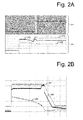
- the architecture is conceived in order to increase the output voltage up to 4.4V - this value depends on the specific feedback circuit implemented - using a constant current of approximately 1 A.
- a small photovoltaic cell is not capable of providing such a high current.
- such a small photovoltaic generator operates in the range of a few mA. Accordingly, a capacitor of, for instance, 100 uF is needed, which is precharged by the photovoltaic generator up to around 3V before the boost converter turns on. This allows the high current required by the boost converter to be provided by the capacitor.
- the boost converter moves to a power save mode if the load does not consume any current. Such behaviour can be better understood with reference to Figures 2A and 2B .
- the purpose of the reference voltage unit 303 is to output a reference voltage V INTarg which is used as a target voltage for the input voltage V INPV received from the first generator 301.
- target voltage it is meant a value at which it is desirable to maintain the input voltage V INPV with the aim of improving the efficiency of first generator 301.
- Reference voltage unit 303 can create reference voltage V INTarg by sensing an output of second generator 302, for instance the value of the open circuit voltage. Assuming that the first and second generator have a similar open circuit voltage, the determination of the open circuit voltage of the second generator readily allows the estimation of the open circuit voltage of the first generator.
- the second generator could have an open circuit voltage different from the open circuit voltage of the first generator, but the relationship between the two values of the open circuit voltages could be known and taken into account when estimating the open circuit voltage of the first generator based on the measured open circuit voltage of the second generator.
- the two comparators compute the error on the input voltage V INPV and on the output voltage V OUT of the energy converter 300. Based on this information, the priority unit 306 controls a converter unit 307, so as to convert the input voltage V INPV to the output voltage V OUT by giving priority to either the stability of the input voltage V INPV or of the output voltage V OUT .
- the regulation of a desired output voltage V OUT can be achieved by maintaining the value of the input voltage V INPV in a range in which efficiency of the first generator 301 is high.
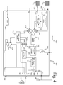
- photovoltaic generator 1102 The purpose of photovoltaic generator 1102 is to provide the energy converter 1000 with the value of the open circuit voltage generated by the second photovoltaic generator 1102 as an estimation of the open circuit voltage that would be generated by first photovoltaic generator 1101, if no load was connected to its output.
- the energy converter 1000 is capable of boosting the value of the voltage V INPV generated by the photovoltaic generator 1101 by means of the booster composed by inductance 1010, diode 1007, transistor 1603 and boost controller 1602. Moreover, the signal based on which the boost controller 1602 boosts the input voltage V INPV to obtain the output voltage V OUT is output from a priority arbitrator 1601.
- the priority arbitrator receives two input signals representing the error on the output voltage V OUT and the error on the input voltage V INPV .
- the error on the input voltage V INPV is generated by amplifier 1303.
- the goal of amplifier 1303 is to ensure that the input voltage V INPV received from photovoltaic generator 1101 is kept close to the ideal value V INTarg , for achieving high power transfer, corresponding to the output of the optimum V IN estimator 1302.
- the error on the output voltage is generated by amplifier 1502.
- Amplifier 1502 generates a voltage error signal if the feedback voltage V OUT received through port FB differs from the reference voltage V REF . Therefore, by a proper selection of the reference voltage V REF , any desired output voltage V OUT can be obtained.
- the optimum V IN estimator 1302 has two inputs connected to the output of a temperature sensor 1301 and to port V PVSS , connected in turn to the second photovoltaic generator 1102.
- the optimum V IN estimator 1302 senses the open voltage value generated by the second photovoltaic generator 1102 thereby acting as a sensing unit.
- the optimum V IN estimator 1302 computes an optimized voltage value V INTarg , which corresponds to a range of 5% to 35%, preferably 15% to 20%, less than the open voltage value generated by the second photovoltaic generator 1102.
- the temperature measured by temperature sensor 1301 can also be taken into account.
- the temperature sensor 1301 is optional and the computation of V INTarg could be based entirely on the open circuit voltage received from the second photovoltaic generator 1102, that is, the correction factor beta could be considered equal to 0.
- the temperature measurement can be realized with an external temp sensor.
- the priority arbitrator 1601 operates so as to ensure that the output voltage V OUT corresponds to the desired reference voltage V REF and to ensure that the input voltage V INPV remains within the range for optimal power generation for the photovoltaic generator. Priority is given to the output voltage V OUT regulation when enough power is produced by the photovoltaic generator 1101. On the other hand, priority is given to the regulation of the input voltage V INPV whenever the power available is less than the power required by the load. Whether enough power is produced by the photovoltaic generator, is judged based on whether the error signal of the input voltage V INPV can be maintained below a certain threshold. If not enough power can be generated, the error on the input voltage V INPV will inevitably tend to increase, thereby indicating that not enough power is available for maintaining the output voltage V OUT to the desired level V REF .
- the energy converter 1000 is further connected to a battery 1201 via a port V BAT1 so as to realize an energy conversion and storage system in accordance with the present invention.
- the energy conversion and storage system is operating with a single battery.
- the present invention is not limited to this and the energy conversion and storage system can be realized with more than one battery and/or with super-capacitors as will be described later.
- the entire power generated by the first photovoltaic generator 1101 could be used to recharge battery 1201.
- a potential load could nevertheless be driven by discharging battery 1202.
- Such a configuration therefore provides the energy converter 1000 of the present invention with a vast range of operating modes and ensures that the load connected to the port V LDO is always operated when required.
- energy converter 1000 includes a VREF generator, together with other analog circuits, represented by block 1501.
- the output V REF of block 1051 is inputted to amplifier 1502.
- the output V REFLDO of block 1501 is inputted to LDO 1701.
- the purpose of voltage V REFLDO is to drive the value of the output voltage V LDO of the LDO 1701.
- block 1501 generates output V RefMAX and V RefMIN which are input to SWAP comparators 1801.
- SWAP comparators 1801 further receive as an input the voltage V BATSENSE .
- the SWAP comparators 1801 are capable of managing the charge/discharge cycles of the batteries. At least two comparators are used. The first one manages the battery during the charge phase and switches whenever the voltage V BATSENSE at the terminals of the battery 1201 has reached a high voltage V RefMAX indicating that the battery is charged.
- battery 1201 can be realized with different technologies. Each technology implies that a certain charge/discharge threshold should be respected in order to increase the battery's life.
- Energy converter 1000 further incorporates charge controller 1803.
- the purpose of charge controller 1803 is to act as a linear charger or as a bypass charger.
- the linear charger mode is employed when charging battery 1201 with a current having a constant value, whenever the input power generated by first photovoltaic generator 1101 is not sufficient for providing battery 1201 with all the current that battery 1201 can sink.
- the bypass mode on the other hand, is employed when there is enough power to let the battery sink all the current it can.
- Charge controller 1803 is turned on and off by charge sequencer 1802 whenever charge sequencer 1802 determines that the battery 1201 has to be charged or not.
- charge controller 1803 is controlled by an output (not shown in the Figures) of priority arbitrator 1601 which decides whether the charge controller 1803 should be operated in a linear mode or in a bypass mode.
- Figure 8 illustrates a third alternative to the first embodiment of Figure 4 .
- battery 4202 could be connected to signals V BATSENSE and V OUT so as to be charged via the power generated by the first photovoltaic generator 1101.
- battery 1201 might also be connected in a manner so as to be charged, or might be disconnected from energy converter 4000, or it might be connected to the signal V OUT so as to help in charging battery 4202, or it maybe connected to the signal V BATOUT in order to help battery 4203 in driving the load through the LDO of 1701.
- switches 4804 might be configured so as to control each of the connection of the plurality of batteries 1201, 4202 and 4203 in an independent manner according to the logic dictated by the charge sequencer 1802.
- T UVLO_OK C IN ⁇ V UVLO x R 2 + R 1 / R 1 / I INPV
- R 1 represents resistance 5009
- R 2 represent resistance 5005
- V UVLO represents the trigger voltage of the UVLO 1403
- C IN represents input capacitance 1006
- I INPV represents the short circuit current provided by first photo voltaic cell 1101
- T UVLO_OK represents the time needed for the UVLO for switching.
- the UVLO 1403 switches, it turns on the analog functions 1501 for the operation of the energy converter.
- the design of the analog functions is carried out so that the current consumed by those functions does not exceed a predetermined level of, for instance, 10uA to 20uA so as to ensure that the load represented by the analog functions does not lower the input voltage V INPV so as to trigger again the UVLO and to turn off the energy converter.
- a logic signal issued from a RC timer (not shown in the Figures) or a signal indicating that the analog functions are active and stabilized (not shown in the Figures) is used in order to activate the boost converter so as to boost the input voltage V INPV to obtain the output voltage V OUT .
- V FB represents the voltage at the node FB
- R 3 represents resistance 5002
- R 4 represent resistance 5001.
- Steps S15 and S140 are executed by a proper connection of switches 1804 by means of charge sequencer 1802. More specifically, in order to drive the load and recharge the battery, node V OUT is connected to node V BATOUT and node V BAT1 .
- the battery recharge step S140 is composed by steps S141, S142 and S143.
- Step S141 consists in recharging the battery, by connecting at least V OUT to V BAT1 .
- step S142 it is judged, by means of SWAP comparators 1801, whether the battery has been charged to a value corresponding to the minimum charge threshold of battery 1201 saved within charge sequencer 1802. If it is judged at step S142 that the battery is charged to at least the minimum charge threshold value, V BATOUT is disconnected from V OUT and the priority arbitrator 1601 is operated so as to convert the power to drive the load. This effectively results in discarding the amount power which could be converted but which is not needed by the load.
- the charge sequencer 1802 is configured to store the information relating to the quality of the batteries (charge level and/or defect) and so as to manage the charge and discharge of the batteries during the operation of the energy converter in an appropriate manner, based on said stored information. For instance, if a battery has been recognized to be defective during a previous check, the charge sequencer can decide not to check the battery again. Moreover, the charge sequencer can decide not to charge and/or discharge the battery.
- a constant voltage charging method is suggested.
- the application of a constant voltage of, for instance, 4.1 V allows the injection in the battery of a current in the range of 10mA to 30mA, in the case of charging at 30°C for a battery of 1mAH.
- a current may not be available from the output of photovoltaic generator 1101.
- the charging of the battery can be done at a constant power instead of a constant voltage.
- the priority arbitrator 1601 is therefore configured so as to detect the divergence of the output voltage V OUT and start a functioning mode in which the charge controller 1803 is employed in linear mode.
- the priority arbitrator 1601 is further configured so as to operate the boost converter in a manner to regulate the input voltage V INPV by transferring current pulses from capacitance 1006 to capacitance 1008.
- the battery discharge step S190 is composed by steps S191 and S192.
- Step S191 consists in discharging the battery, by connecting at least V BAT1 to V BATOUT .
- step S192 it is judged, by means of SWAP comparators 1801, whether the battery has been discharged to a value corresponding to the maximum discharge threshold of battery 1201 saved within charge sequencer 1802. If it is judged that the battery has been discharged to at least a value corresponding to the maximum discharge threshold of battery 1201, steps S18 and S190 are interrupted.
- step S294 it is determined, by the charge sequencer 1802 which battery can be discharged. More specifically, the battery to be discharged is the one having the highest charge value.
- step S191 and S192 it is determined by the charge sequencer 1802 if another battery can be discharged in order to keep driving the load. If yes, then the next battery to be discharged is selected in step S294 as described above. If no, then the driving of the load is interrupted.
- the charge/discharge operation when carried out in the presence of multiple batteries, is advantageous since it provides more flexibility, which results in increased lifetime.
- the system can only charge/discharge the single battery, independently on the charge level in the battery.
- the system can decide which one(s) to charge/discharge so as to try to charge/discharge completely each battery. In this manner, each battery can be operated independently resulting in more flexibility.
- the first battery may be used to drive the load, resulting in a final charge level corresponding to 30% of the capacity.
- the battery might be fully recharged, resulting in a charge cycle of 100% to 30% to 100%, while the second battery remains at 100% throughout the entire cycle. This is advantageous since it improves the lifetime of both batteries.
- the energy converter can be put into a sleep mode.
- a sleep mode only the UVLO 1403 and the comparators 1303 and 1502, as well as the circuits involved in the generation of the reference signals inputted to the comparators, can be kept on. This allows the energy converter to keep following the evolution of the voltages while consuming the smallest amount of power possible.
- FIG 12 illustrates a realisation of an energy converter 7000 according to a second embodiment of the present invention.
- the energy converter 7000 differs from the energy converter 1000 of the first embodiment of the present invention in that the energy is not stored in battery 1201 but in a super capacitor 7201.
- the utilization of a super capacitor 7201 instead of battery 1201 mainly requires the output stage of the energy converter to be modified, in order to take advantage of the way in which the super capacitor is capable of providing power.
- the SWAP comparator 7801 of energy converter 7000 has an additional input TX which is used in order to activate a high-power mode which allows bursts of high current to be delivered to the load, via the LDO 1701, from the super capacitor 7201. This is particularly interesting in the case of RF applications which have a periodical need for high power.
- the energy converter 7000 is capable of providing energy harvested by the photovoltaic cell 1101.
- the energy converter 7000 may further include a PowerOK output used to signal to the external environment that the super capacitor is charged.
- the first embodiment and the second embodiment can be combined. This offers several advantages. Power can be provided by the photovoltaic generator 1101. At the same time, potential excessive power can be stored in the batteries or in the super capacitor. If not enough power is available from the photovoltaic cell, power can be retrieved from the batteries and/or the super capacitor, if a stable amount of current is needed, or from the super capacitor, if a high value of current is need. In this manner, operation of the load is ensured at all time, irrespectively of the kind of current consumption required by the load. Additionally, for instance, if only bursts of high current are needed, power could be transferred from the batteries to the super capacitor.
- priority between the output and input voltage regulation can be managed as described in the first embodiment during the charge of the batteries, while priority can be managed as described in the second embodiment during the charge of the super capacitor. If the battery and super capacitor are charged at the same time, the priority scheme used for the first embodiment can be implemented for both the capacitor and the batteries.
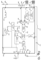
- An energy converter 8000 in accordance with a third embodiment of the present invention is represented in Figure 13 .
- the energy converter 8000 differs from the energy converter 6000 of the first embodiment due to the presence a piezoelectric generator 8103, a thermoelectric generator 8104 and additional components needed for the operation of those two generators.
- the specificity of the piezoelectric source is to deliver a AC power limited to a few mW and to have a high loss impedance. A similar behaviour is also applicable to the thermoelectric source.
- the energy converter 8000 further includes diodes 8014 and 8012, capacitor 8013, switch 8018, inductor 8011, clamp diode 8015, since the piezoelectric generator can create high output voltages, a resistance bridge formed by resistors 8016 and 8017, an optional SW cap regulator 8401, and a AVDD select block 8402 and a UVLO2 8404.
- the charge stored in the input capacitance 8013 is higher than the charge requested by the output capacitance 1008, when charged at the voltage required for recharging the battery. More specifically, the choice of the value of the capacitance 8013 is done so that the UVLO2 is not driven to its lower trigger value once the boost converter is charged. In other words, the value of the capacitance 8013 is enough to guarantee the correct start-up of the boost converter and the charge of the output capacitance 1008, while maintaining a voltage V UVLO2 higher than the lower trigger voltage of the UVLO2. In this manner, undesired turn-off of the energy converter 8000 during start up operation, when power is provided only by the piezoelectric source and/or by the thermoelectric source can be achieved.
- the battery charge current can be limited by the charger.
- the charger can be put in by-pass mode and the boost converter can be operated so as to transfer the charge stored in capacitance 8103 to the battery.
- the piezoelectric generator or the TEG can be used to provide power to the batteries.
- the TEG or piezoelectric generator can be connected to the output through a charge pump regulator.
- thermoelectric generator 8012 instead of a single thermoelectric generator 8012, a plurality of thermoelectric generators 8012 can be connected in series. This provides the additional advantage that the output voltage of the plurality of thermoelectric generators 8012 can be higher than that of a single generator. Moreover, by using such an approach, the design of the energy converter 8000 can be kept simple, since a voltage step-up for the output of thermoelectric generator 8012 is not needed.
- the energy converter may be realized without toxical material unadviced for the living organism and environment, for instance, lead P, Bi2Te3 with bismuth, Sb. Instead, it may be realized with silicon, or any eco-friendly material.
- the operation of the second and third embodiments are similar to the operation of the first embodiment. That is, the management of the charge/discharge cycles of one or a plurality of energy storage elements is similar, independently on the kind of generator used and independently on the kind of energy storage element used.
- the present invention relates to an energy converter capable of converting energy received from a plurality of generators which are capable of harvesting power from the environment.
- the energy converter can convert energy received from the first photovoltaic generator in such a manner than the voltage outputted by the first photovoltaic generator is kept to a level which improves the amount of power generated by the first photovoltaic generator.
- the energy converter of the present invention is capable of extracting power from the first photovoltaic generator that is close to the optimum without requiring a complex solution such as the one represented by the MPPT technique.
- the present invention can relate to an energy conversion and storage system, including the energy converter and at least one energy storage element.
- the current detector 1806 is represented between the node V OUT and the transistor 1805, the present invention is not limited to this. Alternatively, or in addition, the current detector 1806 could be placed between the transistor 1805 and the battery 1201. Still alternatively, or in addition, the current detector 1806 could be placed between the diode 1007 and the node V OUT .
- V INPV could be equal to 20V and V BAT could be equal to 4V at a certain time. Then a buck-boost converter can be operated in a buck mode (downconversion). While, at a different time, V INPV could be equal to 3V and V BAT could be equal to 4V, then a buck-boost converter could be operated in a boost mode (upconversion). This is advantageous in that it provides flexibility depending on the voltage currently outputted by the first photovoltaic generator.
- a buck converter can be implemented instead of a buck-boost converter.
- a boost converter can be implemented instead of a buck-boost converter.
- each generator could be connected in parallel.
- each is providing 4V and the required V BAT is 4V, they could be connected in series.
- the generators could be connected two be two in series and the two series-connected group, could be connected to each other in parallel.
Landscapes
- Engineering & Computer Science (AREA)
- Power Engineering (AREA)
- Charge And Discharge Circuits For Batteries Or The Like (AREA)
- Dc-Dc Converters (AREA)
- Photovoltaic Devices (AREA)
- Life Sciences & Earth Sciences (AREA)
- Sustainable Development (AREA)
- Sustainable Energy (AREA)
Priority Applications (1)
| Application Number | Priority Date | Filing Date | Title |
|---|---|---|---|
| EP20130154270 EP2600488A3 (de) | 2011-01-26 | 2011-01-26 | Energieumwandlungsvorrichtung und -verfahren |
Applications Claiming Priority (2)
| Application Number | Priority Date | Filing Date | Title |
|---|---|---|---|
| EP20130154270 EP2600488A3 (de) | 2011-01-26 | 2011-01-26 | Energieumwandlungsvorrichtung und -verfahren |
| EP20110290046 EP2482332A1 (de) | 2011-01-26 | 2011-01-26 | Energieumwandlungsvorrichtung und -verfahren |
Related Parent Applications (2)
| Application Number | Title | Priority Date | Filing Date |
|---|---|---|---|
| EP20110290046 Division EP2482332A1 (de) | 2011-01-26 | 2011-01-26 | Energieumwandlungsvorrichtung und -verfahren |
| EP11290046.9 Division | 2011-01-26 |
Publications (2)
| Publication Number | Publication Date |
|---|---|
| EP2600488A2 true EP2600488A2 (de) | 2013-06-05 |
| EP2600488A3 EP2600488A3 (de) | 2015-03-11 |
Family
ID=44246351
Family Applications (2)
| Application Number | Title | Priority Date | Filing Date |
|---|---|---|---|
| EP20130154270 Withdrawn EP2600488A3 (de) | 2011-01-26 | 2011-01-26 | Energieumwandlungsvorrichtung und -verfahren |
| EP20110290046 Withdrawn EP2482332A1 (de) | 2011-01-26 | 2011-01-26 | Energieumwandlungsvorrichtung und -verfahren |
Family Applications After (1)
| Application Number | Title | Priority Date | Filing Date |
|---|---|---|---|
| EP20110290046 Withdrawn EP2482332A1 (de) | 2011-01-26 | 2011-01-26 | Energieumwandlungsvorrichtung und -verfahren |
Country Status (5)
| Country | Link |
|---|---|
| US (2) | US9735602B2 (de) |
| EP (2) | EP2600488A3 (de) |
| CN (1) | CN103380498B (de) |
| CA (1) | CA2825454C (de) |
| WO (1) | WO2012100924A1 (de) |
Families Citing this family (24)
| Publication number | Priority date | Publication date | Assignee | Title |
|---|---|---|---|---|
| WO2011106767A2 (en) * | 2010-02-26 | 2011-09-01 | Segway Inc. | Apparatus and methods for control of a vehicle |
| JP5880202B2 (ja) * | 2012-03-27 | 2016-03-08 | 株式会社ソシオネクスト | Dc−dcコンバータ用制御回路、dc−dcコンバータ、及びdc−dcコンバータの制御方法 |
| US20150288179A1 (en) * | 2014-04-02 | 2015-10-08 | Simmonds Precision Products, Inc. | Multiple energy harvester power system |
| US9379615B2 (en) * | 2014-09-17 | 2016-06-28 | Stmicroelectronics S.R.L. | High-efficiency energy harvesting interface and corresponding energy harvesting system |
| TWI519025B (zh) * | 2014-10-21 | 2016-01-21 | 廣達電腦股份有限公司 | 自放電電路 |
| EP3238325A2 (de) | 2014-12-24 | 2017-11-01 | Passive Eye Limited | Verfolgungsvorrichtung und leistungsmodul |
| US10295611B2 (en) | 2015-06-09 | 2019-05-21 | Premier Technologies, Ltd. | Efficient battery tester |
| US20170117730A1 (en) * | 2015-06-26 | 2017-04-27 | The Regents Of The University Of California | Efficient supercapacitor charging technique by a hysteretic charging scheme |
| TWI550380B (zh) * | 2015-12-21 | 2016-09-21 | 新唐科技股份有限公司 | 用於能量採集設備之功率最佳化裝置及方法 |
| TWI626522B (zh) * | 2016-08-15 | 2018-06-11 | 財團法人工業技術研究院 | 功率點追蹤方法及其裝置 |
| US10131245B2 (en) * | 2016-08-16 | 2018-11-20 | Ford Global Technologies, Llc | Electrified vehicle DC power conversion with distributed control |
| JP6770412B2 (ja) | 2016-11-25 | 2020-10-14 | エイブリック株式会社 | 電源装置 |
| FR3066269B1 (fr) * | 2017-05-09 | 2019-07-12 | Commissariat A L'energie Atomique Et Aux Energies Alternatives | Systeme de mesure du niveau de puissance d'une source d'energie ambiante |
| US11157032B2 (en) * | 2017-06-22 | 2021-10-26 | E-Peas S.A. | Power management integrated circuit with optimum power point evaluation |
| JP6935740B2 (ja) * | 2017-12-20 | 2021-09-15 | トヨタ自動車株式会社 | ソーラー発電制御装置及び制御方法 |
| US11695283B2 (en) * | 2018-05-11 | 2023-07-04 | Texas Instruments Incorporated | Shoot-through current limiting circuit |
| CN109343635A (zh) * | 2018-11-15 | 2019-02-15 | 南京铁道职业技术学院 | 一种微小型电源电路 |
| US11114868B2 (en) | 2019-03-07 | 2021-09-07 | Bby Solutions, Inc. | Supplemental capacitor based battery charging system |
| CN110190625A (zh) * | 2019-05-30 | 2019-08-30 | 沈阳工业大学 | 一种双蓄电池混合储能系统优化控制方法 |
| CA3185577A1 (en) * | 2020-07-15 | 2022-01-20 | Linda IRISH | Power balancing solar charging system |
| CN113746190A (zh) * | 2021-08-17 | 2021-12-03 | 湖南工商大学 | 一种单体电压均衡的分布式协同控制方法及系统 |
| US12040608B2 (en) * | 2022-04-12 | 2024-07-16 | Trameto Limited | Power management apparatus for energy harvesting |
| WO2024036200A1 (en) * | 2022-08-09 | 2024-02-15 | Qualcomm Incorporated | Techniques for operating a switched-mode power supply |
| CO2023013484A1 (es) * | 2023-10-12 | 2024-04-18 | Estufas Ecoeficientes Metalcof S A S | Equipo modular híbrido portátil y adaptable, para generación de energía eléctrica, a partir del uso de energía fotovoltáica y termoeléctrica, desde diversas fuentes de calor. |
Family Cites Families (16)
| Publication number | Priority date | Publication date | Assignee | Title |
|---|---|---|---|---|
| US4175249A (en) * | 1978-06-19 | 1979-11-20 | The United States Of America As Represented By The Administrator Of The National Aeronautics And Space Administration | Self-reconfiguring solar cell system |
| US4873480A (en) * | 1988-08-03 | 1989-10-10 | Lafferty Donald L | Coupling network for improving conversion efficiency of photovoltaic power source |
| DE19515786C2 (de) * | 1994-04-28 | 1997-08-21 | Kyocera Corp | Solarenergiesystem |
| US6057665A (en) * | 1998-09-18 | 2000-05-02 | Fire Wind & Rain Technologies Llc | Battery charger with maximum power tracking |
| FR2832870B1 (fr) * | 2001-08-14 | 2006-08-04 | Somfy | Perfectionnement pour chargeur de type photovoltaique |
| US7196494B2 (en) * | 2003-10-17 | 2007-03-27 | Xantrex International | Method and apparatus for charging batteries in a system of batteries |
| JP3887635B2 (ja) * | 2003-10-30 | 2007-02-28 | シャープ株式会社 | 独立電源システム |
| WO2005069096A1 (en) * | 2004-01-12 | 2005-07-28 | Koninklijke Philips Electronics, N.V. | Solar power source with maximum power-point tracking |
| FR2879852A1 (fr) * | 2004-12-22 | 2006-06-23 | France Telecom | Procede et systeme d'alimentation electrique autonome par energie renouvelable |
| US7692411B2 (en) * | 2006-01-05 | 2010-04-06 | Tpl, Inc. | System for energy harvesting and/or generation, storage, and delivery |
| FR2901070B1 (fr) * | 2006-05-11 | 2013-04-26 | Commissariat Energie Atomique | Procede de gestion d'une batterie ou d'un parc de batteries rechargeables utilisant l'effet coup de fouet en charge |
| US20080111517A1 (en) * | 2006-11-15 | 2008-05-15 | Pfeifer John E | Charge Controller for DC-DC Power Conversion |
| ITBS20060216A1 (it) * | 2006-12-12 | 2008-06-13 | Salvatore Agosta | Sistema controllato per pannello solare |
| JP5360968B2 (ja) * | 2008-03-03 | 2013-12-04 | パナソニック株式会社 | 情報処理装置および集積回路 |
| US7969757B2 (en) * | 2008-12-12 | 2011-06-28 | Array Converter, Inc. | Apparatus providing bias to solar cells |
| DE102009018240A1 (de) * | 2009-04-21 | 2010-11-04 | Adensis Gmbh | Photovoltaikanlage mit Batterie und Ersatzkraftwerk |
-
2011
- 2011-01-26 EP EP20130154270 patent/EP2600488A3/de not_active Withdrawn
- 2011-01-26 EP EP20110290046 patent/EP2482332A1/de not_active Withdrawn
-
2012
- 2012-01-18 CA CA2825454A patent/CA2825454C/en not_active Expired - Fee Related
- 2012-01-18 CN CN201280006783.3A patent/CN103380498B/zh not_active Expired - Fee Related
- 2012-01-18 WO PCT/EP2012/000223 patent/WO2012100924A1/en not_active Ceased
- 2012-01-18 US US13/982,018 patent/US9735602B2/en not_active Expired - Fee Related
-
2017
- 2017-07-12 US US15/647,675 patent/US20170310141A1/en not_active Abandoned
Non-Patent Citations (1)
| Title |
|---|
| None |
Also Published As
| Publication number | Publication date |
|---|---|
| CA2825454A1 (en) | 2012-08-02 |
| US20140111015A1 (en) | 2014-04-24 |
| US9735602B2 (en) | 2017-08-15 |
| CN103380498A (zh) | 2013-10-30 |
| US20170310141A1 (en) | 2017-10-26 |
| WO2012100924A9 (en) | 2012-11-08 |
| CA2825454C (en) | 2017-05-09 |
| EP2600488A3 (de) | 2015-03-11 |
| CN103380498B (zh) | 2016-09-21 |
| EP2482332A1 (de) | 2012-08-01 |
| WO2012100924A1 (en) | 2012-08-02 |
Similar Documents
| Publication | Publication Date | Title |
|---|---|---|
| US9735602B2 (en) | Energy converting apparatus and method | |
| US12003134B2 (en) | Supplemental power supply for a battery-powered device | |
| US10396590B2 (en) | Variable power energy harvesting system | |
| Brunelli et al. | An efficient solar energy harvester for wireless sensor nodes | |
| US20120025752A1 (en) | Battery charger | |
| US6590370B1 (en) | Switching DC-DC power converter and battery charger for use with direct oxidation fuel cell power source | |
| US9063559B2 (en) | Battery charger and method for collecting maximum power from energy harvester circuit | |
| US20100060231A1 (en) | Method and Apparatus for Energy Harvesting and/or Generation, Storage, and Delivery | |
| US20080036440A1 (en) | Systems and Methods for Providing Maximum Photovoltaic Peak Power Tracking | |
| US20100244573A1 (en) | Hybrid power delivery system and method | |
| Wang et al. | A single-inductor dual-path three-switch converter with energy-recycling technique for light energy harvesting | |
| Lu et al. | 21.3 A 200nA single-inductor dual-input-triple-output (DITO) converter with two-stage charging and process-limit cold-start voltage for photovoltaic and thermoelectric energy harvesting | |
| CN103094954B (zh) | 控制装置及控制方法 | |
| US10948932B2 (en) | Power management integrated circuit for energy harvesting with multi power mode selection | |
| Chini et al. | Boost-converter-based solar harvester for low power applications | |
| TWI590025B (zh) | 能量轉換裝置和方法 | |
| KR102195448B1 (ko) | 전력관리 집적회로 및 에너지 하베스팅 시스템 | |
| Jessen et al. | Design considerations for a universal smart energy module for energy harvesting in wireless sensor networks | |
| RU2331954C1 (ru) | Способ эксплуатации никель-водородной аккумуляторной батареи в автономной системе электропитания искусственного спутника земли | |
| Huang et al. | A light energy harvesting single-inductor dual-input dual-output converter for WSN | |
| Stojanović et al. | Different Ways to Charging Supercapacitor in WSN Using Solar Cells | |
| CN121942110A (zh) | 高效能量采集系统 |
Legal Events
| Date | Code | Title | Description |
|---|---|---|---|
| PUAI | Public reference made under article 153(3) epc to a published international application that has entered the european phase |
Free format text: ORIGINAL CODE: 0009012 |
|
| AC | Divisional application: reference to earlier application |
Ref document number: 2482332 Country of ref document: EP Kind code of ref document: P |
|
| AK | Designated contracting states |
Kind code of ref document: A2 Designated state(s): AL AT BE BG CH CY CZ DE DK EE ES FI FR GB GR HR HU IE IS IT LI LT LU LV MC MK MT NL NO PL PT RO RS SE SI SK SM TR |
|
| AX | Request for extension of the european patent |
Extension state: BA ME |
|
| PUAL | Search report despatched |
Free format text: ORIGINAL CODE: 0009013 |
|
| AK | Designated contracting states |
Kind code of ref document: A3 Designated state(s): AL AT BE BG CH CY CZ DE DK EE ES FI FR GB GR HR HU IE IS IT LI LT LU LV MC MK MT NL NO PL PT RO RS SE SI SK SM TR |
|
| AX | Request for extension of the european patent |
Extension state: BA ME |
|
| RIC1 | Information provided on ipc code assigned before grant |
Ipc: H02M 3/04 20060101ALN20150203BHEP Ipc: H02J 7/35 20060101AFI20150203BHEP Ipc: H01L 31/02 20060101ALI20150203BHEP |
|
| 17P | Request for examination filed |
Effective date: 20150904 |
|
| RBV | Designated contracting states (corrected) |
Designated state(s): AL AT BE BG CH CY CZ DE DK EE ES FI FR GB GR HR HU IE IS IT LI LT LU LV MC MK MT NL NO PL PT RO RS SE SI SK SM TR |
|
| 17Q | First examination report despatched |
Effective date: 20180316 |
|
| STAA | Information on the status of an ep patent application or granted ep patent |
Free format text: STATUS: THE APPLICATION IS DEEMED TO BE WITHDRAWN |
|
| 18D | Application deemed to be withdrawn |
Effective date: 20180927 |