EP2600098A1 - Surface texture measuring apparatus, method and computer program product - Google Patents
Surface texture measuring apparatus, method and computer program product Download PDFInfo
- Publication number
- EP2600098A1 EP2600098A1 EP12007374.7A EP12007374A EP2600098A1 EP 2600098 A1 EP2600098 A1 EP 2600098A1 EP 12007374 A EP12007374 A EP 12007374A EP 2600098 A1 EP2600098 A1 EP 2600098A1
- Authority
- EP
- European Patent Office
- Prior art keywords
- measurement
- measurement arm
- arm
- detector
- circular arc
- Prior art date
- Legal status (The legal status is an assumption and is not a legal conclusion. Google has not performed a legal analysis and makes no representation as to the accuracy of the status listed.)
- Granted
Links
Images





Classifications
-
- G—PHYSICS
- G01—MEASURING; TESTING
- G01B—MEASURING LENGTH, THICKNESS OR SIMILAR LINEAR DIMENSIONS; MEASURING ANGLES; MEASURING AREAS; MEASURING IRREGULARITIES OF SURFACES OR CONTOURS
- G01B3/00—Measuring instruments characterised by the use of mechanical techniques
- G01B3/002—Details
- G01B3/008—Arrangements for controlling the measuring force
-
- G—PHYSICS
- G01—MEASURING; TESTING
- G01B—MEASURING LENGTH, THICKNESS OR SIMILAR LINEAR DIMENSIONS; MEASURING ANGLES; MEASURING AREAS; MEASURING IRREGULARITIES OF SURFACES OR CONTOURS
- G01B5/00—Measuring arrangements characterised by the use of mechanical techniques
- G01B5/28—Measuring arrangements characterised by the use of mechanical techniques for measuring roughness or irregularity of surfaces
-
- G—PHYSICS
- G01—MEASURING; TESTING
- G01B—MEASURING LENGTH, THICKNESS OR SIMILAR LINEAR DIMENSIONS; MEASURING ANGLES; MEASURING AREAS; MEASURING IRREGULARITIES OF SURFACES OR CONTOURS
- G01B7/00—Measuring arrangements characterised by the use of electric or magnetic techniques
- G01B7/34—Measuring arrangements characterised by the use of electric or magnetic techniques for measuring roughness or irregularity of surfaces
Definitions
- the present invention relates to a surface texture measuring apparatus, method and computer program product. More specifically, the present invention relates to a surface texture measuring apparatus, method and computer program product capable of keeping a measuring force constant regardless of a posture of a measurement arm having a stylus that makes contact with a surface of a measured object.
- a surface texture measuring apparatus which moves a stylus in contact with a surface of a measured object along the surface thereof, detects a displacement of the stylus (displacement in a direction orthogonal to a travel direction of the stylus) generated at this point due to a shape and roughness of the surface of the measured object, and, from the displacement, measures a surface texture such as the shape and roughness of the surface of the measured object.
- a type of surface texture measuring apparatus which pre-prepares styli (measurement arms) of various shapes so as to enable measurement on various shapes of measured portions in a measured object, and performs measurement while switching styli to those which are most appropriate for the shape of the measured portion of the measured object.
- the surface texture measuring apparatus is further capable of tilting a detector main body including the stylus (measurement arm) so as to enable measurement on an inclined surface of the measured object.
- the surface texture measuring apparatus can automatically adjust a measurement force to be appropriate for a combination of a stylus and a measured surface.
- Japanese Patent No. 3992853 describes a technology in which a measurement force command value is pre-stored in a table for each combination of a stylus holder type, a stylus type, a measurement direction, and an inclination angle of the detector main body; a user specifies the stylus holder type, the stylus type, and the measurement direction when a stylus holder or a stylus is changed; a measurement force command value corresponding to the specifications and the inclination angle of the detector main body detected by an angle detector is read out from the table; and the measurement force is automatically adjusted according to the read-out measurement force command value.
- a measurement force it is possible to adjust a measurement force to be most appropriate for the measurement direction (upward or downward, for example) and the inclination angle of the main body in addition to the combination of the stylus holder type and the stylus type. In other words, it is possible to adjust a measurement force to be a predetermined level even when a stylus or a holder is changed, or a measurement direction or an angle is changed.
- Japanese Patent No. 3992853 needs to convert to a table and store in a memory, in advance, each measurement force command value for each combination of the stylus holder type, the stylus type, and the inclination angle of the detector main body.
- each measurement force command value for each combination of the stylus holder type, the stylus type, and the inclination angle of the detector main body Depending on a shape of the measured object, there may be a desire to use an apparatus with an inclination angle other than that stored in the table. In such a case, the technology described in Japanese Patent No. 3992853 cannot perform accurate measurement because a measurement force command value for the desired inclination angle is not stored.
- a particular advantage of the present invention is to provide a surface texture measuring apparatus capable of performing accurate measurement even when an inclination angle of a detector displacement mechanism is changed to a specified (predetermined or predeterminable) angle, while achieving a smaller memory capacity and reducing a workload for a user even when use of a new stylus is desired.
- a surface texture measuring apparatus which includes a detector, a stage, a relative displacement mechanism, and a detector inclination mechanism.
- the detector has a measurement arm, a displacement detector, and a measurement force applier.
- the measurement arm is supported by a main body in a state capable of performing circular arc motion pivoting on a supporting axis as a supporting point and is provided with a stylus particularly at a tip thereof.
- the displacement detector detects an amount of circular arc motion of the measurement arm.
- the measurement force applier urges the measurement arm in a circular arc motion direction and applies a measurement force to the stylus.
- the stage carries a measured object.
- the relative displacement mechanism includes a detector displacement mechanism moving the detector in an axis direction of the measurement arm, and relatively moves the detector and the stage.
- the detector inclination mechanism tilts a movement direction of the detector displacement mechanism with respect to the stage.
- the displacement detector detects the amount of circular arc motion of the measurement arm while the relative displacement mechanism relatively moves the detector and the stage. A surface texture of the measured object is then measured based on the circular arc motion amount.
- the measurement arm is configured with a first measurement arm supported by the main body in a state capable of performing a circular arc motion pivoting on the supporting axis as a supporting point, and a second measurement arm attachably and detachably provided (particularly at a tip of) the first measurement arm via an attach-detach mechanism and having the stylus particularly at a tip.
- the surface texture measuring apparatus further includes a measurement arm table (also referred to as a memory), a measurement arm specifier, an inclination angle information provider, and a control device.
- the measurement arm table stores a mass M of an entire measurement arm, an arm length L from the supporting point to the stylus, and a horizontal barycenter Gx and a vertical barycenter Gz of the measurement arm in a horizontal posture, for each type of the measurement arm to which a second measurement arm having a different mass is attached.
- the measurement arm specifier specifies a type of the measurement arm.
- the inclination angle information provider provides information on an inclination angle of the detector inclined by the detector inclination mechanism.
- the control device reads out from the measurement arm table the mass M, the arm length L, the horizontal barycenter Gx, and the vertical barycenter Gz for the measurement arm specified by the measurement arm specifier.
- the control device further calculates a difference between a measurement force of the measurement arm in the horizontal posture and a measurement force of the measurement arm in the inclined posture based on the information from the measurement arm table and the inclination angle information from the inclination angle information provider. The control device then adjusts a measurement force of the measurement force applier using the difference as a correction value.
- the measurement arm specifier specifies a measurement arm including the post-replacement second measurement arm.
- the control device then reads out from the measurement arm table the mass M, the arm length L, the horizontal barycenter Gx, and the vertical barycenter Gz for the specified measurement arm. Based on this information and the inclination angle information provided from the inclination angle information provider, a difference between the measurement force of the measurement arm in the horizontal posture and the measurement force of the measurement arm in the inclined posture is calculated. The measurement force of the measurement force provider is adjusted using the difference as a correction value.
- a most appropriate measurement force can be obtained by calculation from the mass M, the arm length L, the horizontal barycenter Gx, the vertical barycenter Gz, and the inclination angle information.
- required memory capacity can be reduced since only one set of parameters (the mass M of the entire measurement arm, the arm length L, the horizontal barycenter Gx, and the vertical barycenter Gz) for each type of the measurement arm including the second measurement arm needs to be stored.
- the user when a user wants to use a new measurement arm, the user does not need to register the measurement force command value thereof. Instead, the user only needs to register parameters, which the user can relatively easily obtain. Thus, it is possible to reduce the user's workload.
- the inclination angle information provider is preferably configured with an inclination angle detector detecting an inclination angle of the detector. According to such a configuration, the inclination angle of the detector is automatically detected by the inclination angle detector. Thereby, the burden of the user can be reduced. In other words, because a user does not have to manually input the inclination angle of the detector through an inputter, it is possible to reduce the burden of the user.
- the difference between the measurement force of the measurement arm in the horizontal posture and the measurement force of the measurement arm in the inclined posture is automatically calculated from the mass M of the entire measurement arm, the arm length L, the horizontal barycenter Gx, the vertical barycenter Gz, and the inclination angle ⁇ 1 of the detector.
- a measurement can be performed with a proper measurement force.
- the measurement arm specifier preferably includes a mass calculator obtaining the mass of the entire measurement arm including the post-replacement second measurement arm when the second measurement arm is replaced with respect to the first measurement arm.
- the control device also preferably performs calculation by reading out from the measurement arm table the arm length L, the horizontal barycenter Gx, and the vertical barycenter Gz for the measurement arm corresponding to the mass calculated by the mass calculator. According to such a configuration, when the second measurement arm is replaced with respect to the first measurement arm, the mass calculator obtains the mass of the entire measurement arm including the post-replacement second measurement arm.
- the control device then reads out from the measurement arm table the arm length L, the horizontal barycenter Gx, and the vertical barycenter Gz for the measurement arm corresponding to the mass calculated by the mass calculator, and automatically performs calculation. Accordingly, it is not necessary for a user to specify the measurement arm including the second measurement arm. Thereby, it is possible to eliminate specifying errors and to reduce the burden of the user.
- the measurement force applier preferably includes a voice coil urging the measurement arm in the circular arc motion direction pivoting on the supporting axis as a supporting point.
- the mass calculator preferably adjusts an electric current conducted in the voice coil while monitoring the circular arc motion amount of the measurement arm detected by the displacement detector and obtains the mass of the post-replacement measurement arm by comparing a measurement force in a state where the circular arc motion amount of a reference measurement arm has become a specified (predetermined or predeterminable) set value and a measurement force in a state where the circular arc motion amount of the post-replacement measurement arm has become a specified (predetermined or predeterminable) set value.
- the electric current conducted in the voice coil is adjusted while the circular arc motion amount of the measurement arm detected by the displacement detector is monitored, and the mass of the post-replacement measurement arm is obtained by comparing the measurement force in a state where the circular arc motion amount of the reference measurement arm has become a specified (predetermined or predeterminable) set value and the measurement force in a state where the circular arc motion amount of the post-replacement measurement arm has become a specified (predetermined or predeterminable) set value.
- the post-replacement measurement arm can be automatically identified. Therefore, the user's work can be reduced.
- a surface texture measuring method comprising the following steps: carrying a measured object on a stage; supporting a measurement arm by a main body the measurement arm being configured to move in a circular arc pivoting on a supporting axis as a supporting point and being provided with at least one stylus; detecting an amount of circular arc motion of the measurement arm; and urging the measurement arm in a circular arc motion direction by means of a measurement force applier, the measurement force applier further configured to apply a measurement force to the stylus; in a state where the stylus is in contact with a surface of the measured object, detecting the amount of circular arc motion of the measurement arm while relatively moving the detector and the stage; and measuring a surface texture of the measured object based on the amount of circular arc motion amount; wherein the measurement arm comprises a first measurement arm supported by the main body in a state capable of performing circular arc motion pivoting on the supporting axis as a supporting point, and a second measurement arm attachably and detachably provided at
- the surface texture measuring method further comprises obtaining the mass of the entirety of the measurement arm including a post-replacement second measurement arm when the second measurement arm is replaced with respect to the first measurement arm; and performing calculation by determining the arm length L, the horizontal barycenter Gx, and the vertical barycenter Gz, for the measurement arm corresponding to the mass calculated by the mass calculator.
- the surface texture measuring method further comprises urging the measurement arm by means of a voice coil in the circular arc motion direction pivoting on the supporting axis as a supporting point; adjusting an electric current conducted in the voice coil while monitoring the detected amount of circular arc motion of the measurement arm and obtaining the mass of the post-replacement measurement arm by comparing a measurement force in a state where the circular arc motion amount of the measurement arm to serve as a reference has become a specified set value and a measurement force in a state where the circular arc motion of the post-replacement measurement arm has become a specified set value.
- a computer program product in particular tangibly embodied on a computer-readable storage, as a signal or data stream, comprising computer-readable instructions which, when loaded and executed on a suitable system, perform the steps of a surface texture measuring method according to the above aspect of the invention or a particular aspect thereof.
- a surface texture measuring apparatus includes, as shown in Fig. 1 , a base 1, a stage 10 placed on the base 1 and carrying a measured object on an upper surface thereof, a stylus displacement detector 20 having styli 26A and 26B that are to be brought into contact with a surface of the measured object, and a relative displacement mechanism (relative displacer) 40 that moves the stylus displacement detector 20 and the stage 10 relative to each other.
- the relative displacement mechanism 40 includes a Y-axis drive mechanism 41 that is provided between the base 1 and the stage 10 and moves the stage 10 in one horizontal direction (Y-axis direction), a column 42 erected on an upper surface of the base 1, a Z-slider 43 provided movably in a vertical direction (Z-axis direction) along the column 42, a Z-axis drive mechanism 44 that raises and lowers the Z-slider 43 in the vertical direction, and an X-axis drive mechanism 45 provided to the Z-slider 43 and moving the stylus displacement detector 20 in a perpendicular direction (X-axis direction: axis direction of a measurement arm 24 (described later)) with respect to a displacement direction (Y-axis direction) of the stage 10 and a displacement direction (Z-axis direction) of the Z-slider 43.
- Y-axis drive mechanism 41 that is provided between the base 1 and the stage 10 and moves the stage 10 in one horizontal direction (Y-axis direction)
- the relative displacement mechanism 40 is configured with a three-dimensional displacement mechanism including the Y-axis drive mechanism 41 that moves the stage 10 in the Y-axis direction, the Z-axis drive mechanism 44 that moves the stylus displacement detector 20 in the Z-axis direction, and the X-axis drive mechanism 45 as a particular detector displacement mechanism (detector displacer) that moves the stylus displacement detector 20 in the X-axis direction (axis direction of the measurement arm 24).
- a swivel mechanism 30 is provided between the Z-slider 43 and the X-axis drive mechanism 45 as a particular detector inclination mechanism (detector inclinator) that inclines a displacement direction of the X-axis drive mechanism 45 with respect to the stage 10.
- the stylus displacement detector 20, along with the X-axis drive mechanism 45 is configured to be able to change a posture thereof to an inclined posture in addition to a horizontal posture.
- the Y-axis drive mechanism 41 and the Z-axis drive mechanism 44 are configured with, for example, a feed screw mechanism (omitted from the drawings) having a ball screw shaft and a nut threadably mounted on the ball screw shaft.
- the X-axis drive mechanism 45 includes, as shown in Fig.
- the feed mechanism 50 is configured with a feed screw shaft 51, a motor 52 as a particular drive source, and a rotation transmission mechanism 53.
- the feed screw shaft 51 is provided to the drive mechanism main body 46 in parallel to the guide rail 47 and is threadably mounted to the X-slider 48.
- the rotation transmission mechanism 53 transmits rotation of the motor 52 to the feed screw shaft 51.
- the rotation transmission mechanism 53 is configured with a mechanism including, for example, a gear train, a belt, a pulley, and the like.
- the stylus displacement detector 20 includes, as shown in Fig. 2 , a bracket 22, the measurement arm 24, one or more, particularly a pair of styli 26A and 26B provided at or near a tip of the measurement arm 24, a displacement detector 27, a balance weight 29, a measurement arm posture switching mechanism 60, and a casing 28.
- the bracket 22 acts as a particular main body and is detachably hung and supported by the X-slider 48 via a bolt 21.
- the measurement arm 24 is supported by the bracket 22 to be swingable in the vertical direction (movable in a circular arc direction) pivoting on a rotation axis 23 as a particular supporting axis.
- the displacement detector 27 detects or determines an amount of circular arc motion (displacement amount in the Z-axis direction) of the measurement arm 24.
- the balance weight 29 is provided to the measurement arm 24 such that a position thereof is adjustable.
- the measurement arm posture switching mechanism 60 switches a position of the measurement arm 24 between a position urged in a direction (upward, for example) of the circular arc motion direction or a position urged in the other direction (downward).
- the casing 28 at least partly covers the bracket 22, the measurement arm 24, the displacement detector 27, the balance weight 29, and the measurement arm posture switching mechanism 60.
- the measurement arm 24 particularly is configured with a first measurement arm 24A and a second measurement arm 24B.
- the first measurement arm 24A is supported by the bracket 22 so as to be able to perform a circular arc motion in the vertical direction pivoting on the rotation axis 23.
- the second measurement arm 24B is replaceably provided at or near a tip of the first measurement arm 24A via an attach-detach mechanism (attacher-detacher) 25.
- the attach-detach mechanism 25 particularly has a magnetic mechanism that pulls and attaches the first measurement arm 24A and the second measurement arm 24B by a magnetic force.
- the styli 26A and 26B protrude from the second measurement arm 24B in the circular arc motion direction. That is, an upward stylus 26A and a downward stylus 26B protrude in an up-down direction perpendicular to the second measurement arm 24B.
- the displacement detector 27 is provided to follow a range of a circular arc motion of the measurement arm 24, as shown in Fig. 3 .
- the displacement detector 27 is configured with a position detector outputting pulse signals particularly in a number corresponding to the amount of the circular arc motion of the measurement arm 24.
- the displacement detector 27 is configured with a scale 27A and a detection head 27B.
- the scale 27A is provided to the measurement arm 24 and is curved in the direction of the circular arc motion of the measurement arm 24.
- the detection head 27B is attached to the bracket 22 acting as the main body so as to face the scale 27A.
- a detection surface of the scale 27A is placed on an axis line of the measurement arm 24 and also on a surface defined by the circular arc motion of the measurement arm 24.
- the balance weight 29 is provided such that the position thereof is adjustable in an axis direction of the measurement arm 24 so that a weight of a first measurement arm 24A side and a weight of a second measurement arm 24B side are balanced at the rotation axis 23 as a particular supporting point.
- the balance weight 29 is fixed at a desired (predetermined or predeterminable) position of the measurement arm 24 by a screw.
- a male screw may be formed on the measurement arm 24 and the balance weight 29 may be position-adjustably screwed to the male screw.
- the measurement arm posture switching mechanism 60 is configured with a tubular magnet 61 and a voice coil 62.
- the magnet 61 is provided in the middle or at an intermediate position of the first measurement arm 24A.
- the voice coil 62 passes through the interior of the magnet 61, is fixed to the bracket 22 acting as the main body, and urges the measurement arm 24 in one direction (upward) or the other direction (downward) of the circular arc motion direction pivoting on the rotation axis 23.
- the measurement arm posture switching mechanism 60 is controlled by a command from a measurement posture and measurement force control circuit 70.
- the measurement arm posture switching mechanism 60 includes the voice coil 62 urging the measurement arm 24 in the circular arc motion direction pivoting on the rotation axis 23 and particularly also serves as a measurement force applier that applies a measurement force to the styli 26A and 26B by urging the measurement arm 24 in the circular arc motion direction.
- the measurement posture and measurement force control circuit 70 includes a command signal generator 72, a digital-to-analog converter 73, and a constant current circuit 76.
- the command signal generator 72 generates a voltage corresponding to a measurement force command value output from a control device 101 (described later).
- the digital-to-analog converter 73 converts the voltage (digital signal) from the command signal generator 72 into an analog signal.
- the constant current circuit 76 converts the voltage from the digital-to-analog converter 73 into an electric current and applies the electric current to the voice coil 62 of the measurement arm posture switching mechanism 60.
- Fig. 6 illustrates a control system for the present surface texture measuring apparatus.
- the control device (controller) 101 is connected with the Y-axis drive mechanism 41, the Z-axis drive mechanism 44, the X-axis drive mechanism 45, the swivel mechanism 30, an inclination angle detector 31 detecting an inclination angle of the X-axis drive mechanism 45, the displacement detector 27 included in the stylus displacement detector 20, and the measurement arm posture switching mechanism 60 (via the measurement posture and measurement force control circuit 70).
- the control device 101 is further connected with an inputter 102, an outputter 103, a memory device 104, and the like.
- the inclination angle detector 31 configures an inclination angle information provider that provides information on an inclination angle ⁇ 1 of the stylus displacement detector 20 inclined by the swivel mechanism 30.
- the memory device 104 is provided with a measurement arm table 105 and an inclination angle memory 106 in addition to a memory that stores data detected or determined by the displacement detector 27.
- the measurement arm table 105 stores information indicative of a mass M of the entire measurement arm 24, an arm length L from a supporting point (rotation axis 23) of the measurement arm 24 to the styli 26A and 26B, and a horizontal barycenter Gx (X-axis direction position from the supporting point) and a vertical direction barycenter Gz (Z-axis direction position from the supporting point) of the measurement arm 24 in a horizontal posture, for each type of the measurement arm 24 in which a second measurement arm 24B (A21 to A27) having a different mass is attached.
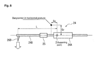
- Fig. 8 illustrates the arm length L, the horizontal barycenter Gx, and the vertical barycenter Gz of the measurement arm 24 in the horizontal posture.
- the inclination angle memory 106 stores the inclination angle ⁇ 1 of the X-axis drive mechanism 45 detected by the inclination angle detector 31. From the inputter 102, information specifying the type of the measurement arm 24 is input. In this embodiment, the inputter 102 particularly also serves as a measurement arm specifier.
- the control device 101 reads out or retrieves or determines from the measurement arm table 105 the mass M, the arm length L, the horizontal barycenter Gx, and the vertical barycenter Gz for the measurement arm 24 specified by the inputter 102. Based on this information and the inclination angle ⁇ 1 information provided from the inclination angle memory 106, the control device 101 calculates a difference between a measurement force of the measurement arm 24 in the horizontal posture and a measurement force of the measurement arm 24 in the inclined posture. Using this difference as a correction value, the control device 101 then adjusts a measurement force of the measurement arm posture switching mechanism 60 acting as a particular measurement force applier.
- control device 101 configures a balance adjuster that adjusts the balance of the measurement arm 24 by adjusting an electric current conducted in the voice coil 62 of the measurement arm posture switching mechanism 60 when the second measurement arm 24B is replaced with respect to the first measurement arm 24A. Specifically, the control device 101 configures the balance adjuster that adjusts the electric current conducted in the voice coil 62 while monitoring the circular arc motion amount of the measurement arm 24 detected by the displacement detector 27 and that completes the balance adjustment when the circular arc motion amount of the measurement arm 24 reaches a specified (predetermined or predeterminable) set value.
- the second measurement arm 24B is replaced with one having the styli 26A and 26B appropriate for the measurement surface of the measured object.
- the replacing second measurement arm 24B is pulled and held by the first measurement arm 24A via the attach-detach mechanism 25.
- the swivel mechanism 30 is spun or displaced such that the movement direction of the X-axis drive mechanism 45 is parallel to the measurement surface of the measured object. Since the stylus displacement detector 20 tilts along with the X-axis drive mechanism 45 when the swivel mechanism 30 is swirled, the movement direction of the X-axis drive mechanism 45 is adjusted to be parallel to the measurement surface of the measured object. Then, the inclination angle ⁇ 1 of the X-axis drive mechanism 45 and the stylus displacement detector 20 is detected by the inclination angle detector 31 and is stored in the inclination angle memory 106.
- the stylus 26B of the measurement arm 24 is positioned on the upper surface of the measured object.
- the type of the measurement arm 24 including the post-replacement second measurement arm 24B is then input through the inputter 102.
- the control device 101 reads out from the measurement arm table 105 the mass M, the arm length L, the horizontal barycenter Gx, and the vertical barycenter Gz corresponding to the input type of the measurement arm 24.
- the control device 101 provides a measurement force command value, which is a corrected calculated difference, to the measurement posture and measurement force control circuit 70.
- the measurement posture and measurement force control circuit 70 applies an electric current corresponding to the measurement force command value to the voice coil 62 of the measurement arm posture switching mechanism 60.
- the stylus 26B is brought into contact with the measurement surface of the measured object at the measurement force command value.
- the relative displacement mechanism 40 relatively displaces the stylus displacement detector 20 and the stage 10 in the axis direction of the measurement arm 24.
- the displacement detector 27 detects the circular arc motion amount of the measurement arm 24. Based on the circular arc motion amount, the surface texture of the measured object is measured.
- the type of the measurement arm 24 by specifying the type of the measurement arm 24, it is possible to calculate and obtain a most appropriate measurement force from the mass M, the arm length L, the horizontal barycenter Gx, the vertical barycenter Gz, and the inclination angle ⁇ 1.
- required memory capacity can be reduced since only one set of parameters (the mass M of the entire measurement arm, the arm length L, the horizontal barycenter Gx, and the vertical barycenter Gz) for each type of the measurement arm 24 including the second measurement arm 24B needs to be stored.
- the user when a user wants to use a new measurement arm 24, the user does not need to register the measurement force command value thereof. Instead, the user only needs to register parameters (the mass M of the entire measurement arm, the arm length L, the horizontal barycenter Gx, and the vertical barycenter Gz), which the user can relatively easily obtain.
- the workload of the user can be reduced.
- the present embodiment since the present embodiment includes the inclination angle detector 31 that detects the inclination angle of the stylus displacement detector 20, it is possible to automatically detect the inclination angle of the stylus displacement detector 20. Accordingly, it is not necessary for a user to manually input the inclination angle of the stylus displacement detector 20 through the inputter 102. Thereby, the burden of the user can be reduced.
- the present invention is not limited to the above-described embodiment, and modifications and improvements thereon are included in the present invention as long as the advantage of the present invention can be achieved.
- the type of the measurement arm 24 including the post-replacement second measurement arm 24B is input through the inputter 102.
- a mass of an entire measurement arm including a post-replacement second measurement arm may be calculated.
- the balance adjuster of the control device 101 herein particularly configures a mass calculator.
- Step (abbreviated as ST, hereinafter) 1 the control device 101 outputs a setting command for a measurement force of 0 mN. Thereafter, monitoring on a value of the displacement detector 27 is started in ST 2. After outputting a setting command for a given measurement force in ST 3, the control device 101 checks whether an amount of change in the value of the displacement detector 27 for a specified (predetermined or predeterminable) time period is within a specified (predetermined or predeterminable) range in ST 4.
- the processing proceeds to ST 5.
- the setting command for a measurement force is output with a direction reverse to a direction in which the value of the displacement detector 27 changes.
- the processing of ST 5 is repeated until the amount of change in the value of the displacement detector 27 for the specified (predetermined or predeterminable) time period becomes a value within the specified (predetermined or predeterminable) range.
- a series of processes shown in Fig. 11 is performed with respect to a post-replacement measurement arm 24.
- the series of processes from ST 1 to ST 6 is the same as that in Fig. 10 .
- a measurement force A for the balanced reference measurement arm 24 and a measurement force B for the balanced post-replacement measurement arm 24 are compared, and the mass of the post-replacement measurement arm 24 is calculated by the following formula.
- Mass of post - replacement measurement arm Measurement force A - Measurement force B
- the mass of the post-replacement measurement arm 24 is obtained. Thereby, it particularly is not necessary for a user to specify the measurement arm 24 including the second measurement arm 24B. Accordingly, it is possible to eliminate specifying errors and to reduce the user's burden.
- the inclination angle ⁇ 1 of the stylus displacement detector 20 and the X-axis drive mechanism 45 particularly is detected by the inclination angle detector 31, and the control device 101 performs calculation using the detected inclination angle ⁇ 1.
- the inclination angle ⁇ 1 of the stylus displacement detector 20 and the X-axis drive mechanism 45 may be manually input through the inputter 102.
- the measurement arm posture switching mechanism 60 particularly has a configuration including the voice coil 62 that urges the measurement arm 24 in one or the other direction of the circular arc motion direction pivoting on the rotation axis 23 as a particular supporting point, however, the configuration of the measurement arm posture switching mechanism 60 is not limited to this.
- a mechanism using a linear motor mechanism may be employed.
- the circular arc motion is performed in the vertical direction in the above-described embodiment, it may be performed in the horizontal direction.
- a configuration is also possible in which swing motion is performed in a diagonal direction other than the vertical and horizontal directions.
- the second measurement arm 24B particularly having the pair of styli 26A and 26B at the tip of the measurement arm 24 has been explained.
- the configuration does not need to include the pair of styli.
- any configuration may be employed.
- the relative displacement mechanism 40 is configured to be capable of moving the stage 10 in the Y-axis direction and the stylus displacement detector 20 in the X-axis direction and the Z-axis direction.
- the configuration is not limited to the above. In essence, as long as the stage 10 and the stylus displacement detector 20 can move in three-dimensional directions, either of them may move.
- the present invention may be used when measurement is performed on an inclined surface or the like of a measured object.
- a surface texture measuring apparatus which includes a measurement arm table storing mass of an entire measurement arm, an arm length from a supporting point to a stylus, and a horizontal and vertical barycenter of the measurement arm in a horizontal posture for each type of the measurement arm in which a second measurement arm having a different mass is attached; a measurement arm specifier; an inclination angle detector detecting an inclination angle of the detector; and a controller reading out from the measurement arm table the mass, the arm length, the horizontal barycenter, and the vertical barycenter for a specified measurement arm, calculating a difference between a measurement force of the measurement arm in the horizontal posture and a measurement force of the measurement arm in an inclined posture based on the read-out information and the inclination angle detected by the inclination angle detector, and adjusting a measurement force.
Landscapes
- Physics & Mathematics (AREA)
- General Physics & Mathematics (AREA)
- A Measuring Device Byusing Mechanical Method (AREA)
- Measurement Of The Respiration, Hearing Ability, Form, And Blood Characteristics Of Living Organisms (AREA)
- Length Measuring Devices With Unspecified Measuring Means (AREA)
Abstract
Description
- The present invention relates to a surface texture measuring apparatus, method and computer program product. More specifically, the present invention relates to a surface texture measuring apparatus, method and computer program product capable of keeping a measuring force constant regardless of a posture of a measurement arm having a stylus that makes contact with a surface of a measured object.
- A surface texture measuring apparatus is known which moves a stylus in contact with a surface of a measured object along the surface thereof, detects a displacement of the stylus (displacement in a direction orthogonal to a travel direction of the stylus) generated at this point due to a shape and roughness of the surface of the measured object, and, from the displacement, measures a surface texture such as the shape and roughness of the surface of the measured object.
- Among the surface texture measuring apparatuses, a type of surface texture measuring apparatus has been suggested which pre-prepares styli (measurement arms) of various shapes so as to enable measurement on various shapes of measured portions in a measured object, and performs measurement while switching styli to those which are most appropriate for the shape of the measured portion of the measured object. The surface texture measuring apparatus is further capable of tilting a detector main body including the stylus (measurement arm) so as to enable measurement on an inclined surface of the measured object. In addition, the surface texture measuring apparatus can automatically adjust a measurement force to be appropriate for a combination of a stylus and a measured surface.
- For example, Japanese Patent No.
3992853 - Thus, it is possible to adjust a measurement force to be most appropriate for the measurement direction (upward or downward, for example) and the inclination angle of the main body in addition to the combination of the stylus holder type and the stylus type. In other words, it is possible to adjust a measurement force to be a predetermined level even when a stylus or a holder is changed, or a measurement direction or an angle is changed.
- The technology described in Japanese Patent No.
3992853 3992853 - In addition, when an inclination angle for the detector main body is allowed to be finely specified, required memory capacity is significantly increased. Further, when a user wants to use an unregistered stylus, the user needs to obtain a measurement force command value for the new stylus that the user wants to use, the stylus holder type, the measurement direction, and the inclination angle, which increases the user's workload.
- Accordingly, it is an object of the present invention to allow a measurement of a surface texture while keeping a measuring force constant regardless of a posture of a measurement arm having a stylus that makes contact with a surface of a measured object.
- This object is solved according to the invention by the features of the independent claims. Particular embodiments of the invention are subject of the dependent claims.
- A particular advantage of the present invention is to provide a surface texture measuring apparatus capable of performing accurate measurement even when an inclination angle of a detector displacement mechanism is changed to a specified (predetermined or predeterminable) angle, while achieving a smaller memory capacity and reducing a workload for a user even when use of a new stylus is desired.
- According to one aspect of the invention, there is provided a surface texture measuring apparatus which includes a detector, a stage, a relative displacement mechanism, and a detector inclination mechanism. The detector has a measurement arm, a displacement detector, and a measurement force applier. The measurement arm is supported by a main body in a state capable of performing circular arc motion pivoting on a supporting axis as a supporting point and is provided with a stylus particularly at a tip thereof. The displacement detector detects an amount of circular arc motion of the measurement arm. The measurement force applier urges the measurement arm in a circular arc motion direction and applies a measurement force to the stylus. The stage carries a measured object. The relative displacement mechanism includes a detector displacement mechanism moving the detector in an axis direction of the measurement arm, and relatively moves the detector and the stage. The detector inclination mechanism tilts a movement direction of the detector displacement mechanism with respect to the stage. In a state where the stylus is in contact with a surface of the measured object, the displacement detector detects the amount of circular arc motion of the measurement arm while the relative displacement mechanism relatively moves the detector and the stage. A surface texture of the measured object is then measured based on the circular arc motion amount. In such a surface texture measuring apparatus, the measurement arm is configured with a first measurement arm supported by the main body in a state capable of performing a circular arc motion pivoting on the supporting axis as a supporting point, and a second measurement arm attachably and detachably provided (particularly at a tip of) the first measurement arm via an attach-detach mechanism and having the stylus particularly at a tip. The surface texture measuring apparatus further includes a measurement arm table (also referred to as a memory), a measurement arm specifier, an inclination angle information provider, and a control device. The measurement arm table stores a mass M of an entire measurement arm, an arm length L from the supporting point to the stylus, and a horizontal barycenter Gx and a vertical barycenter Gz of the measurement arm in a horizontal posture, for each type of the measurement arm to which a second measurement arm having a different mass is attached. The measurement arm specifier specifies a type of the measurement arm. The inclination angle information provider provides information on an inclination angle of the detector inclined by the detector inclination mechanism. The control device reads out from the measurement arm table the mass M, the arm length L, the horizontal barycenter Gx, and the vertical barycenter Gz for the measurement arm specified by the measurement arm specifier. The control device further calculates a difference between a measurement force of the measurement arm in the horizontal posture and a measurement force of the measurement arm in the inclined posture based on the information from the measurement arm table and the inclination angle information from the inclination angle information provider. The control device then adjusts a measurement force of the measurement force applier using the difference as a correction value.
- According to such a configuration, after the second measurement arm is replaced so as to correspond to the surface shape of the measured object, the measurement arm specifier specifies a measurement arm including the post-replacement second measurement arm. The control device then reads out from the measurement arm table the mass M, the arm length L, the horizontal barycenter Gx, and the vertical barycenter Gz for the specified measurement arm. Based on this information and the inclination angle information provided from the inclination angle information provider, a difference between the measurement force of the measurement arm in the horizontal posture and the measurement force of the measurement arm in the inclined posture is calculated. The measurement force of the measurement force provider is adjusted using the difference as a correction value.
- Accordingly, by specifying the type of the measurement arm, a most appropriate measurement force can be obtained by calculation from the mass M, the arm length L, the horizontal barycenter Gx, the vertical barycenter Gz, and the inclination angle information. Thereby, it is possible to accurately measure a measurement surface of the measured object having any angle. Further, required memory capacity can be reduced since only one set of parameters (the mass M of the entire measurement arm, the arm length L, the horizontal barycenter Gx, and the vertical barycenter Gz) for each type of the measurement arm including the second measurement arm needs to be stored. In addition, when a user wants to use a new measurement arm, the user does not need to register the measurement force command value thereof. Instead, the user only needs to register parameters, which the user can relatively easily obtain. Thus, it is possible to reduce the user's workload.
- In the above surface texture measuring apparatus, the inclination angle information provider is preferably configured with an inclination angle detector detecting an inclination angle of the detector. According to such a configuration, the inclination angle of the detector is automatically detected by the inclination angle detector. Thereby, the burden of the user can be reduced. In other words, because a user does not have to manually input the inclination angle of the detector through an inputter, it is possible to reduce the burden of the user.
- In the above surface texture measuring apparatus, the control device preferably obtains the difference between the measurement force of the measurement arm in the horizontal posture and the measurement force of the measurement arm in the inclined posture from the mass M of the entire measurement arm, the arm length L, the horizontal barycenter Gx, the vertical barycenter Gz, and an inclination angle θ1 of the detector with a formula:

where


- According to such a configuration, the difference between the measurement force of the measurement arm in the horizontal posture and the measurement force of the measurement arm in the inclined posture is automatically calculated from the mass M of the entire measurement arm, the arm length L, the horizontal barycenter Gx, the vertical barycenter Gz, and the inclination angle θ1 of the detector. Thus, a measurement can be performed with a proper measurement force.
- In the above surface texture measuring apparatus, the measurement arm specifier preferably includes a mass calculator obtaining the mass of the entire measurement arm including the post-replacement second measurement arm when the second measurement arm is replaced with respect to the first measurement arm. The control device also preferably performs calculation by reading out from the measurement arm table the arm length L, the horizontal barycenter Gx, and the vertical barycenter Gz for the measurement arm corresponding to the mass calculated by the mass calculator. According to such a configuration, when the second measurement arm is replaced with respect to the first measurement arm, the mass calculator obtains the mass of the entire measurement arm including the post-replacement second measurement arm. The control device then reads out from the measurement arm table the arm length L, the horizontal barycenter Gx, and the vertical barycenter Gz for the measurement arm corresponding to the mass calculated by the mass calculator, and automatically performs calculation. Accordingly, it is not necessary for a user to specify the measurement arm including the second measurement arm. Thereby, it is possible to eliminate specifying errors and to reduce the burden of the user.
- In the above surface texture measuring apparatus, the measurement force applier preferably includes a voice coil urging the measurement arm in the circular arc motion direction pivoting on the supporting axis as a supporting point. The mass calculator preferably adjusts an electric current conducted in the voice coil while monitoring the circular arc motion amount of the measurement arm detected by the displacement detector and obtains the mass of the post-replacement measurement arm by comparing a measurement force in a state where the circular arc motion amount of a reference measurement arm has become a specified (predetermined or predeterminable) set value and a measurement force in a state where the circular arc motion amount of the post-replacement measurement arm has become a specified (predetermined or predeterminable) set value. According to such a configuration, the electric current conducted in the voice coil is adjusted while the circular arc motion amount of the measurement arm detected by the displacement detector is monitored, and the mass of the post-replacement measurement arm is obtained by comparing the measurement force in a state where the circular arc motion amount of the reference measurement arm has become a specified (predetermined or predeterminable) set value and the measurement force in a state where the circular arc motion amount of the post-replacement measurement arm has become a specified (predetermined or predeterminable) set value. Thereby, the post-replacement measurement arm can be automatically identified. Therefore, the user's work can be reduced.
According to a further aspect, there is provided a surface texture measuring method comprising the following steps: carrying a measured object on a stage; supporting a measurement arm by a main body the measurement arm being configured to move in a circular arc pivoting on a supporting axis as a supporting point and being provided with at least one stylus; detecting an amount of circular arc motion of the measurement arm; and urging the measurement arm in a circular arc motion direction by means of a measurement force applier, the measurement force applier further configured to apply a measurement force to the stylus; in a state where the stylus is in contact with a surface of the measured object, detecting the amount of circular arc motion of the measurement arm while relatively moving the detector and the stage; and measuring a surface texture of the measured object based on the amount of circular arc motion amount; wherein the measurement arm comprises a first measurement arm supported by the main body in a state capable of performing circular arc motion pivoting on the supporting axis as a supporting point, and a second measurement arm attachably and detachably provided at the first measurement arm via an attacher-detacher and having the stylus; and
wherein the method further comprises: determining information indicative of: a mass M of an entirety of the measurement arm, an arm length L from the supporting point to the stylus, and a horizontal barycenter Gx and a vertical barycenter Gz of the measurement arm in a horizontal position, for each type of the measurement arm in which the second measurement arm having a different mass is attached;specifying the type of the measurement arm; providing information on an inclination angle of the detector as inclined; and calculating a difference between a measurement force of the measurement arm in the horizontal position and a measurement force of the measurement arm in an inclined position based on the determined information and the inclination angle information from the inclination angle information provider, and outputting at least one signal to adjust a measurement force of the measurement force applier using the difference as a correction value.
Particularly, the surface texture measuring method further comprises detecting an inclination angle of the detector.
Further particularly, the surface texture measuring method further comprises obtaining the difference between the measurement force of the measurement arm in the horizontal position and the measurement force of the measurement arm in the inclined position from the mass M of the entire measurement arm, the arm length L, the horizontal barycenter Gx, the vertical barycenter Gz, and an inclination angle θ1 of the detector with a formula:
where


- Further particularly, the surface texture measuring method further comprises obtaining the mass of the entirety of the measurement arm including a post-replacement second measurement arm when the second measurement arm is replaced with respect to the first measurement arm; and performing calculation by determining the arm length L, the horizontal barycenter Gx, and the vertical barycenter Gz, for the measurement arm corresponding to the mass calculated by the mass calculator.
- Further particularly, the surface texture measuring method further comprises urging the measurement arm by means of a voice coil in the circular arc motion direction pivoting on the supporting axis as a supporting point; adjusting an electric current conducted in the voice coil while monitoring the detected amount of circular arc motion of the measurement arm and obtaining the mass of the post-replacement measurement arm by comparing a measurement force in a state where the circular arc motion amount of the measurement arm to serve as a reference has become a specified set value and a measurement force in a state where the circular arc motion of the post-replacement measurement arm has become a specified set value.
- According to a further aspect of the present invention, there is provided a computer program product, in particular tangibly embodied on a computer-readable storage, as a signal or data stream, comprising computer-readable instructions which, when loaded and executed on a suitable system, perform the steps of a surface texture measuring method according to the above aspect of the invention or a particular aspect thereof..
- The present invention is further described in the detailed description which follows, in reference to the noted plurality of drawings by way of non-limiting examples of exemplary embodiments of the present invention, in which like reference numerals represent similar parts throughout the several views of the drawings. It should be understood that even though embodiments are separately described, single features thereof may be combined to additional embodiments.
-
Fig. 1 is a perspective view showing a surface texture measuring apparatus according to an embodiment of the present invention; -
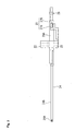
Fig. 2 illustrates an X-axis drive mechanism and a stylus displacement detector of the same embodiment; -
Fig. 3 is a plan view showing a relationship between a measurement arm and a displacement detector of the same embodiment; -
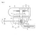
Fig. 4 illustrates the measurement arm and a measurement arm posture switching mechanism of the same embodiment; -
Fig. 5 illustrates a measurement posture and measurement force control circuit of the same embodiment; -
Fig. 6 is a block diagram showing a control system of the same embodiment; -
Fig. 7 illustrates a measurement arm table of the same embodiment; -
Fig. 8 illustrates parameters of the measurement arm of the same embodiment; -
Fig. 9 illustrates the parameters of the measurement arm in an inclined posture of the same embodiment; -
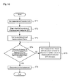
Fig. 10 is a flowchart showing steps to adjust balance of a reference measurement arm of another embodiment; and -
Fig. 11 is a flowchart showing steps to obtain a mass of a post-replacement measurement arm of another embodiment. - The particulars shown herein are by way of example and for purposes of illustrative discussion of the embodiments of the present invention only and are presented in the cause of providing what is believed to be the most useful and readily understood description of the principles and conceptual aspects of the present invention. In this regard, no attempt is made to show structural details of the present invention in more detail than is necessary for the fundamental understanding of the present invention, the description is taken with the drawings making apparent to those skilled in the art how the forms of the present invention may be embodied in practice.
- A surface texture measuring apparatus according to the present embodiment includes, as shown in
Fig. 1 , abase 1, astage 10 placed on thebase 1 and carrying a measured object on an upper surface thereof, astylus displacement detector 20 havingstyli stylus displacement detector 20 and thestage 10 relative to each other. - The
relative displacement mechanism 40 includes a Y-axis drive mechanism 41 that is provided between thebase 1 and thestage 10 and moves thestage 10 in one horizontal direction (Y-axis direction), acolumn 42 erected on an upper surface of thebase 1, a Z-slider 43 provided movably in a vertical direction (Z-axis direction) along thecolumn 42, a Z-axis drive mechanism 44 that raises and lowers the Z-slider 43 in the vertical direction, and anX-axis drive mechanism 45 provided to the Z-slider 43 and moving thestylus displacement detector 20 in a perpendicular direction (X-axis direction: axis direction of a measurement arm 24 (described later)) with respect to a displacement direction (Y-axis direction) of thestage 10 and a displacement direction (Z-axis direction) of the Z-slider 43. - Accordingly, the
relative displacement mechanism 40 is configured with a three-dimensional displacement mechanism including the Y-axis drive mechanism 41 that moves thestage 10 in the Y-axis direction, the Z-axis drive mechanism 44 that moves thestylus displacement detector 20 in the Z-axis direction, and theX-axis drive mechanism 45 as a particular detector displacement mechanism (detector displacer) that moves thestylus displacement detector 20 in the X-axis direction (axis direction of the measurement arm 24). Further, aswivel mechanism 30 is provided between the Z-slider 43 and theX-axis drive mechanism 45 as a particular detector inclination mechanism (detector inclinator) that inclines a displacement direction of theX-axis drive mechanism 45 with respect to thestage 10. Thereby, thestylus displacement detector 20, along with theX-axis drive mechanism 45, is configured to be able to change a posture thereof to an inclined posture in addition to a horizontal posture. - The Y-
axis drive mechanism 41 and the Z-axis drive mechanism 44 are configured with, for example, a feed screw mechanism (omitted from the drawings) having a ball screw shaft and a nut threadably mounted on the ball screw shaft. TheX-axis drive mechanism 45 includes, as shown inFig. 2 , a drive mechanismmain body 46 fixed to the Z-slider 43 via theswivel mechanism 30, aguide rail 47 provided to the drive mechanismmain body 46 in parallel to the X-axis direction, an X-slider 48 provided movably in the X-axis direction along theguide rail 47, anX-axis position detector 49 detecting an X-axis direction position of the X-slider 48, and afeed mechanism 50 moving the X-slider 48 along theguide rail 47. Thefeed mechanism 50 is configured with afeed screw shaft 51, amotor 52 as a particular drive source, and arotation transmission mechanism 53. Thefeed screw shaft 51 is provided to the drive mechanismmain body 46 in parallel to theguide rail 47 and is threadably mounted to the X-slider 48. Therotation transmission mechanism 53 transmits rotation of themotor 52 to thefeed screw shaft 51. Therotation transmission mechanism 53 is configured with a mechanism including, for example, a gear train, a belt, a pulley, and the like. - The
stylus displacement detector 20 includes, as shown inFig. 2 , abracket 22, themeasurement arm 24, one or more, particularly a pair ofstyli measurement arm 24, adisplacement detector 27, abalance weight 29, a measurement armposture switching mechanism 60, and acasing 28. Thebracket 22 acts as a particular main body and is detachably hung and supported by the X-slider 48 via abolt 21. Themeasurement arm 24 is supported by thebracket 22 to be swingable in the vertical direction (movable in a circular arc direction) pivoting on arotation axis 23 as a particular supporting axis. Thedisplacement detector 27 detects or determines an amount of circular arc motion (displacement amount in the Z-axis direction) of themeasurement arm 24. Thebalance weight 29 is provided to themeasurement arm 24 such that a position thereof is adjustable. The measurement armposture switching mechanism 60 switches a position of themeasurement arm 24 between a position urged in a direction (upward, for example) of the circular arc motion direction or a position urged in the other direction (downward). Thecasing 28 at least partly covers thebracket 22, themeasurement arm 24, thedisplacement detector 27, thebalance weight 29, and the measurement armposture switching mechanism 60. - The
measurement arm 24 particularly is configured with afirst measurement arm 24A and asecond measurement arm 24B. Thefirst measurement arm 24A is supported by thebracket 22 so as to be able to perform a circular arc motion in the vertical direction pivoting on therotation axis 23. Thesecond measurement arm 24B is replaceably provided at or near a tip of thefirst measurement arm 24A via an attach-detach mechanism (attacher-detacher) 25. The attach-detachmechanism 25 particularly has a magnetic mechanism that pulls and attaches thefirst measurement arm 24A and thesecond measurement arm 24B by a magnetic force. Thestyli second measurement arm 24B in the circular arc motion direction. That is, anupward stylus 26A and adownward stylus 26B protrude in an up-down direction perpendicular to thesecond measurement arm 24B. - The
displacement detector 27 is provided to follow a range of a circular arc motion of themeasurement arm 24, as shown inFig. 3 . Thedisplacement detector 27 is configured with a position detector outputting pulse signals particularly in a number corresponding to the amount of the circular arc motion of themeasurement arm 24. Specifically, thedisplacement detector 27 is configured with ascale 27A and adetection head 27B. Thescale 27A is provided to themeasurement arm 24 and is curved in the direction of the circular arc motion of themeasurement arm 24. Thedetection head 27B is attached to thebracket 22 acting as the main body so as to face thescale 27A. A detection surface of thescale 27A is placed on an axis line of themeasurement arm 24 and also on a surface defined by the circular arc motion of themeasurement arm 24. Accordingly, the detection surface of thescale 27A, themeasurement arm 24, and each tip of thestyli balance weight 29 is provided such that the position thereof is adjustable in an axis direction of themeasurement arm 24 so that a weight of afirst measurement arm 24A side and a weight of asecond measurement arm 24B side are balanced at therotation axis 23 as a particular supporting point. Specifically, thebalance weight 29 is fixed at a desired (predetermined or predeterminable) position of themeasurement arm 24 by a screw. Alternatively, a male screw may be formed on themeasurement arm 24 and thebalance weight 29 may be position-adjustably screwed to the male screw. - As shown in
Fig. 4 , the measurement armposture switching mechanism 60 is configured with atubular magnet 61 and avoice coil 62. Themagnet 61 is provided in the middle or at an intermediate position of thefirst measurement arm 24A. Thevoice coil 62 passes through the interior of themagnet 61, is fixed to thebracket 22 acting as the main body, and urges themeasurement arm 24 in one direction (upward) or the other direction (downward) of the circular arc motion direction pivoting on therotation axis 23. The measurement armposture switching mechanism 60 is controlled by a command from a measurement posture and measurementforce control circuit 70. When an electric current flows in thevoice coil 62 in response to the command from the measurement posture and measurementforce control circuit 70, themagnet 61 of themeasurement arm 24 is attracted to thevoice coil 62 due to an electromagnetic force generated from thevoice coil 62 and a magnetic force of themagnet 61. The posture of themeasurement arm 24 is thus switched to a posture in which the tip of themeasurement arm 24 is urged upward or downward. In this embodiment, the measurement armposture switching mechanism 60 includes thevoice coil 62 urging themeasurement arm 24 in the circular arc motion direction pivoting on therotation axis 23 and particularly also serves as a measurement force applier that applies a measurement force to thestyli measurement arm 24 in the circular arc motion direction. - As shown in
Fig. 5 , the measurement posture and measurementforce control circuit 70 includes acommand signal generator 72, a digital-to-analog converter 73, and a constantcurrent circuit 76. Thecommand signal generator 72 generates a voltage corresponding to a measurement force command value output from a control device 101 (described later). The digital-to-analog converter 73 converts the voltage (digital signal) from thecommand signal generator 72 into an analog signal. The constantcurrent circuit 76 converts the voltage from the digital-to-analog converter 73 into an electric current and applies the electric current to thevoice coil 62 of the measurement armposture switching mechanism 60. -
Fig. 6 illustrates a control system for the present surface texture measuring apparatus. The control device (controller) 101 is connected with the Y-axis drive mechanism 41, the Z-axis drive mechanism 44, theX-axis drive mechanism 45, theswivel mechanism 30, aninclination angle detector 31 detecting an inclination angle of theX-axis drive mechanism 45, thedisplacement detector 27 included in thestylus displacement detector 20, and the measurement arm posture switching mechanism 60 (via the measurement posture and measurement force control circuit 70). Thecontrol device 101 is further connected with aninputter 102, anoutputter 103, amemory device 104, and the like. Theinclination angle detector 31 configures an inclination angle information provider that provides information on an inclination angle θ1 of thestylus displacement detector 20 inclined by theswivel mechanism 30. - The
memory device 104 is provided with a measurement arm table 105 and aninclination angle memory 106 in addition to a memory that stores data detected or determined by thedisplacement detector 27. As shown inFig. 7 , the measurement arm table 105 stores information indicative of a mass M of theentire measurement arm 24, an arm length L from a supporting point (rotation axis 23) of themeasurement arm 24 to thestyli measurement arm 24 in a horizontal posture, for each type of themeasurement arm 24 in which asecond measurement arm 24B (A21 to A27) having a different mass is attached. Further,Fig. 8 illustrates the arm length L, the horizontal barycenter Gx, and the vertical barycenter Gz of themeasurement arm 24 in the horizontal posture. - The
inclination angle memory 106 stores the inclination angle θ1 of theX-axis drive mechanism 45 detected by theinclination angle detector 31. From theinputter 102, information specifying the type of themeasurement arm 24 is input. In this embodiment, theinputter 102 particularly also serves as a measurement arm specifier. - The
control device 101 reads out or retrieves or determines from the measurement arm table 105 the mass M, the arm length L, the horizontal barycenter Gx, and the vertical barycenter Gz for themeasurement arm 24 specified by theinputter 102. Based on this information and the inclination angle θ1 information provided from theinclination angle memory 106, thecontrol device 101 calculates a difference between a measurement force of themeasurement arm 24 in the horizontal posture and a measurement force of themeasurement arm 24 in the inclined posture. Using this difference as a correction value, thecontrol device 101 then adjusts a measurement force of the measurement armposture switching mechanism 60 acting as a particular measurement force applier. Specifically, from the mass M of the entire measurement arm, the arm length L, the horizontal barycenter Gx, the vertical barycenter Gz, and the inclination angle θ1 of the detector, the difference between the measurement force of themeasurement arm 24 in the horizontal posture and the measurement force of themeasurement arm 24 in the inclined posture is obtained with the following formula (1):
where


- Further, the
control device 101 configures a balance adjuster that adjusts the balance of themeasurement arm 24 by adjusting an electric current conducted in thevoice coil 62 of the measurement armposture switching mechanism 60 when thesecond measurement arm 24B is replaced with respect to thefirst measurement arm 24A. Specifically, thecontrol device 101 configures the balance adjuster that adjusts the electric current conducted in thevoice coil 62 while monitoring the circular arc motion amount of themeasurement arm 24 detected by thedisplacement detector 27 and that completes the balance adjustment when the circular arc motion amount of themeasurement arm 24 reaches a specified (predetermined or predeterminable) set value. - In performing measurement, the
second measurement arm 24B is replaced with one having thestyli second measurement arm 24B is pulled and held by thefirst measurement arm 24A via the attach-detachmechanism 25. Subsequently, theswivel mechanism 30 is spun or displaced such that the movement direction of theX-axis drive mechanism 45 is parallel to the measurement surface of the measured object. Since thestylus displacement detector 20 tilts along with theX-axis drive mechanism 45 when theswivel mechanism 30 is swirled, the movement direction of theX-axis drive mechanism 45 is adjusted to be parallel to the measurement surface of the measured object. Then, the inclination angle θ1 of theX-axis drive mechanism 45 and thestylus displacement detector 20 is detected by theinclination angle detector 31 and is stored in theinclination angle memory 106. - Thereafter, the
stylus 26B of themeasurement arm 24 is positioned on the upper surface of the measured object. The type of themeasurement arm 24 including the post-replacementsecond measurement arm 24B is then input through theinputter 102. Then, thecontrol device 101 reads out from the measurement arm table 105 the mass M, the arm length L, the horizontal barycenter Gx, and the vertical barycenter Gz corresponding to the input type of themeasurement arm 24. Based on this information and the inclination angle θ1 stored in theinclination angle memory 106, a difference between a measurement force of themeasurement arm 24 in the horizontal posture and a measurement force of themeasurement arm 24 in the inclined posture is obtained with the following formula (1):
where


Further,Fig. 9 illustrates the barycenter Gx' and θ1 to θ3 of themeasurement arm 24 in the inclined posture. - Subsequently, the
control device 101 provides a measurement force command value, which is a corrected calculated difference, to the measurement posture and measurementforce control circuit 70. Then, the measurement posture and measurementforce control circuit 70 applies an electric current corresponding to the measurement force command value to thevoice coil 62 of the measurement armposture switching mechanism 60. As a result, thestylus 26B is brought into contact with the measurement surface of the measured object at the measurement force command value. In this state, therelative displacement mechanism 40 relatively displaces thestylus displacement detector 20 and thestage 10 in the axis direction of themeasurement arm 24. Thedisplacement detector 27 then detects the circular arc motion amount of themeasurement arm 24. Based on the circular arc motion amount, the surface texture of the measured object is measured. - According to the present embodiment, by specifying the type of the
measurement arm 24, it is possible to calculate and obtain a most appropriate measurement force from the mass M, the arm length L, the horizontal barycenter Gx, the vertical barycenter Gz, and the inclination angle θ1. Thus, it is possible to perform accurate measurement on a measurement surface of a measured object having any angle. Further, required memory capacity can be reduced since only one set of parameters (the mass M of the entire measurement arm, the arm length L, the horizontal barycenter Gx, and the vertical barycenter Gz) for each type of themeasurement arm 24 including thesecond measurement arm 24B needs to be stored. In addition, when a user wants to use anew measurement arm 24, the user does not need to register the measurement force command value thereof. Instead, the user only needs to register parameters (the mass M of the entire measurement arm, the arm length L, the horizontal barycenter Gx, and the vertical barycenter Gz), which the user can relatively easily obtain. Thus, the workload of the user can be reduced. - In particular, since the present embodiment includes the
inclination angle detector 31 that detects the inclination angle of thestylus displacement detector 20, it is possible to automatically detect the inclination angle of thestylus displacement detector 20. Accordingly, it is not necessary for a user to manually input the inclination angle of thestylus displacement detector 20 through theinputter 102. Thereby, the burden of the user can be reduced. - The present invention is not limited to the above-described embodiment, and modifications and improvements thereon are included in the present invention as long as the advantage of the present invention can be achieved. In the above-described embodiment, in performing measurement, the type of the
measurement arm 24 including the post-replacementsecond measurement arm 24B is input through theinputter 102. However, using the balance adjuster in thecontrol device 101, a mass of an entire measurement arm including a post-replacement second measurement arm may be calculated. By reading out from the measurement arm table 105 the arm length L, the horizontal barycenter Gx, and the vertical barycenter Gz of themeasurement arm 24 corresponding to the calculated mass, a calculation may be further performed. The balance adjuster of thecontrol device 101 herein particularly configures a mass calculator. - Specifically, a series of processes shown in
Fig. 10 is first performed with respect to a reference measurement arm (measurement arm in which thesecond measurement arm 24B having a reference mass is attached to thefirst measurement arm 24A). In Step (abbreviated as ST, hereinafter) 1, thecontrol device 101 outputs a setting command for a measurement force of 0 mN. Thereafter, monitoring on a value of thedisplacement detector 27 is started inST 2. After outputting a setting command for a given measurement force inST 3, thecontrol device 101 checks whether an amount of change in the value of thedisplacement detector 27 for a specified (predetermined or predeterminable) time period is within a specified (predetermined or predeterminable) range inST 4. InST 4, in a case where the amount of change in the value of thedisplacement detector 27 for the specified (predetermined or predeterminable) period is not within the specified (predetermined or predeterminable) range, that is, in a case where thereference measurement arm 24 greatly loses its balance, the processing proceeds toST 5. The setting command for a measurement force is output with a direction reverse to a direction in which the value of thedisplacement detector 27 changes. InST 4, the processing ofST 5 is repeated until the amount of change in the value of thedisplacement detector 27 for the specified (predetermined or predeterminable) time period becomes a value within the specified (predetermined or predeterminable) range. InST 4, when the amount of change in the value of thedisplacement detector 27 for the specified (predetermined or predeterminable) time period becomes a value within the specified (predetermined or predeterminable) range, it is determined that themeasurement arm 24 is balanced inST 6, and the processing is completed. - Subsequently, a series of processes shown in
Fig. 11 is performed with respect to apost-replacement measurement arm 24. The series of processes fromST 1 toST 6 is the same as that inFig. 10 . InST 7, a measurement force A for the balancedreference measurement arm 24 and a measurement force B for the balancedpost-replacement measurement arm 24 are compared, and the mass of thepost-replacement measurement arm 24 is calculated by the following formula.
In other words, while the circular arc motion amount of themeasurement arm 24 detected by thedisplacement detector 27 is monitored, the electric current conducted in thevoice coil 62 is or can be adjusted. Then, by comparing a measurement force in a state where the circular arc motion amount of thereference measurement arm 24 has become a specified (predetermined or predeterminable) set value and a measurement force in a state where the circular arc motion amount of thepost-replacement measurement arm 24 has become a specified (predetermined or predeterminable) set value, the mass of thepost-replacement measurement arm 24 is obtained. Thereby, it particularly is not necessary for a user to specify themeasurement arm 24 including thesecond measurement arm 24B. Accordingly, it is possible to eliminate specifying errors and to reduce the user's burden. - In the above-described embodiment, the inclination angle θ1 of the
stylus displacement detector 20 and theX-axis drive mechanism 45 particularly is detected by theinclination angle detector 31, and thecontrol device 101 performs calculation using the detected inclination angle θ1. However, the inclination angle θ1 of thestylus displacement detector 20 and theX-axis drive mechanism 45 may be manually input through theinputter 102. - In the above-described embodiment, the measurement arm
posture switching mechanism 60 particularly has a configuration including thevoice coil 62 that urges themeasurement arm 24 in one or the other direction of the circular arc motion direction pivoting on therotation axis 23 as a particular supporting point, however, the configuration of the measurement armposture switching mechanism 60 is not limited to this. For example, a mechanism using a linear motor mechanism may be employed. In addition, although the circular arc motion is performed in the vertical direction in the above-described embodiment, it may be performed in the horizontal direction. Alternatively, a configuration is also possible in which swing motion is performed in a diagonal direction other than the vertical and horizontal directions. - In the above-described embodiment, the
second measurement arm 24B particularly having the pair ofstyli measurement arm 24 has been explained. However, the configuration does not need to include the pair of styli. As long as a measurement arm can be replaced to one having a stylus appropriate for a measured portion, any configuration may be employed. - Further, the
relative displacement mechanism 40 is configured to be capable of moving thestage 10 in the Y-axis direction and thestylus displacement detector 20 in the X-axis direction and the Z-axis direction. However, the configuration is not limited to the above. In essence, as long as thestage 10 and thestylus displacement detector 20 can move in three-dimensional directions, either of them may move. - The present invention may be used when measurement is performed on an inclined surface or the like of a measured object.
- Accordingly, there is described a surface texture measuring apparatus which includes a measurement arm table storing mass of an entire measurement arm, an arm length from a supporting point to a stylus, and a horizontal and vertical barycenter of the measurement arm in a horizontal posture for each type of the measurement arm in which a second measurement arm having a different mass is attached; a measurement arm specifier; an inclination angle detector detecting an inclination angle of the detector; and a controller reading out from the measurement arm table the mass, the arm length, the horizontal barycenter, and the vertical barycenter for a specified measurement arm, calculating a difference between a measurement force of the measurement arm in the horizontal posture and a measurement force of the measurement arm in an inclined posture based on the read-out information and the inclination angle detected by the inclination angle detector, and adjusting a measurement force.
- It is noted that the foregoing examples have been provided merely for the purpose of explanation and are in no way to be construed as limiting of the present invention. While the present invention has been described with reference to exemplary embodiments, it is understood that the words which have been used herein are words of description and illustration, rather than words of limitation. Changes may be made, within the purview of the appended claims, as presently stated and as amended, without departing from the scope and spirit of the present invention in its aspects. Although the present invention has been described herein with reference to particular structures, materials and embodiments, the present invention is not intended to be limited to the particulars disclosed herein; rather, the present invention extends to all functionally equivalent structures, methods and uses, such as are within the scope of the appended claims.
- The present invention is not limited to the above described embodiments, and various variations and modifications may be possible without departing from the scope of the present invention.
Claims (11)
- A surface texture measuring apparatus comprising:a detector (20) comprising:a measurement arm (24) supported by a main body (22) and configured to move in a circular arc pivoting on a supporting axis (23) as a supporting point and provided with at least one stylus (26A; 26B);a displacement detector (27) configured to detect an amount of circular arc motion of the measurement arm (24); anda measurement force applier (60) configured to urge the measurement arm (24) in a circular arc motion direction, the measurement force applier (60) further configured to apply a measurement force to the stylus (26A; 26B);a stage (10) configured to carry a measured object;a relative displacer (40) comprising a detector displacer (45) configured to move the detector (20) in an axis direction of the measurement arm (24), the relative displacer (40) further configured to relatively move the detector (20) and the stage (10);a detector inclinator (30) tilting a movement direction of the detector displacer (45) with respect to the stage (10), wherein:in a state where the stylus (26A; 26B) is in contact with a surface of the measured object, the displacement detector (27) detects the amount of circular arc motion of the measurement arm (24) while the relative displacer (40) relatively moves the detector (20) and the stage (10);a surface texture of the measured object is to be measured based on the amount of circular arc motion amount; andthe measurement arm (24) comprises a first measurement arm (24A) supported by the main body (22) in a state capable of performing circular arc motion pivoting on the supporting axis as a supporting point, and a second measurement arm (24B) attachably and detachably provided at the first measurement arm (24A) via an attacher-detacher (25) and having the stylus (26A; 26B);a memory (104) configured to store information indicative of:a mass M of an entirety of the measurement arm (24),an arm length L from the supporting point to the stylus (26A; 26B), anda horizontal barycenter Gx and a vertical barycenter Gz of the measurement arm (24) in a horizontal position,for each type of the measurement arm (24) in which the second measurement arm (24B) having a different mass is attached;a measurement arm specifier (102) configured to specify the type of the measurement arm (24);an inclination angle information provider configured to provide information on an inclination angle of the detector (20) inclined by the detector inclinator (30); anda controller (101) configured to:read out from the memory (104) the mass M, the arm length L, the horizontal barycenter Gx, and the vertical barycenter Gz for the measurement arm (24) specified by the measurement arm specifier (102);calculate a difference between a measurement force of the measurement arm (24) in the horizontal position and a measurement force of the measurement arm (24) in an inclined position based on the information from the memory (104) and the inclination angle information from the inclination angle information provider, andadjust a measurement force of the measurement force applier (60) using the difference as a correction value.
- The surface texture measuring apparatus according to claim 1, wherein the inclination angle information provider comprises an inclination angle detector (31) configured to detect an inclination angle of the detector (20).
- The surface texture measuring apparatus according to any one of the preceding claims, wherein the controller (101) is further configured to obtain the difference between the measurement force of the measurement arm (24) in the horizontal position and the measurement force of the measurement arm (24) in the inclined position from the mass M of the entire measurement arm (24), the arm length L, the horizontal barycenter Gx, the vertical barycenter Gz, and an inclination angle θ1 of the detector (20) with a formula:

where


- The surface texture measuring apparatus according to any one of the preceding claims, wherein:the measurement arm specifier (102) comprises a mass calculator configured to obtain the mass of the entirety of the measurement arm (24) including a post-replacement second measurement arm when the second measurement arm (24B) is replaced with respect to the first measurement arm (24A); andthe controller (101) is further configured to perform calculation by reading out from the memory (104) the arm length L, the horizontal barycenter Gx, and the vertical barycenter Gz, for the measurement arm (24) corresponding to the mass calculated by the mass calculator.
- The surface texture measuring apparatus according to claim 4, wherein:the measurement force applier (60) includes a voice coil (62) configured to urge the measurement arm (24) in the circular arc motion direction pivoting on the supporting axis (23) as a supporting point; andthe mass calculator is configured to adjust an electric current conducted in the voice coil (62) while monitoring the amount of circular arc motion of the measurement arm (24) detected by the displacement detector (27) and obtains the mass of the post-replacement measurement arm by comparing a measurement force in a state where the circular arc motion amount of the measurement arm (24) to serve as a reference has become a specified set value and a measurement force in a state where the circular arc motion of the post-replacement measurement arm has become a specified set value.
- A surface texture measuring method comprising the following steps:carrying a measured object on a stage (10);supporting a measurement arm (24) by a main body (22) the measurement arm (24) being configured to move in a circular arc pivoting on a supporting axis (23) as a supporting point and being provided with at least one stylus (26A; 26B);detecting an amount of circular arc motion of the measurement arm (24); andurging the measurement arm (24) in a circular arc motion direction by means of a measurement force applier (60), the measurement force applier (60) further configured to apply a measurement force to the stylus (26A; 26B);in a state where the stylus (26A; 26B) is in contact with a surface of the measured object, detecting the amount of circular arc motion of the measurement arm (24) while relatively moving the detector (20) and the stage (10); andmeasuring a surface texture of the measured object based on the amount of circular arc motion amount;wherein the measurement arm (24) comprises a first measurement arm (24A) supported by the main body (22) in a state capable of performing circular arc motion pivoting on the supporting axis as a supporting point, and a second measurement arm (24B) attachably and detachably provided at the first measurement arm (24A) via an attacher-detacher (25) and having the stylus (26A; 26B); and
wherein the method further comprises- determining information indicative of:a mass M of an entirety of the measurement arm (24),an arm length L from the supporting point to the stylus (26A; 26B), anda horizontal, barycenter Gx and a vertical barycenter Gz of the measurement arm (24) in a horizontal position,for each type of the measurement arm (24) in which the second measurement arm (24B) having a different mass is attached;- specifying the type of the measurement arm (24);- providing information on an inclination angle of the detector (20) as inclined;
and- calculating a difference between a measurement force of the measurement arm (24) in the horizontal position and a measurement force of the measurement arm (24) in an inclined position based on the determined information and the inclination angle information from the inclination angle information provider, and- outputting at least one signal to adjust a measurement force of the measurement force applier (60) using the difference as a correction value. - The surface texture measuring method according to claim 6, further comprising detecting an inclination angle of the detector (20).
- The surface texture measuring method according to claim 6 or 7, further comprising obtaining the difference between the measurement force of the measurement arm (24) in the horizontal position and the measurement force of the measurement arm (24) in the inclined position from the mass M of the entire measurement arm (24), the arm length L, the horizontal barycenter Gx, the vertical barycenter Gz, and an inclination angle θ1 of the detector (20) with a formula:

where


- The surface texture measuring method according to any one of the preceding claims 6 to 8, further comprising:obtaining the mass of the entirety of the measurement arm (24) including a post-replacement second measurement arm when the second measurement arm (24B) is replaced with respect to the first measurement arm (24A); andperforming calculation by determining the arm length L, the horizontal barycenter Gx, and the vertical barycenter Gz, for the measurement arm (24) corresponding to the mass calculated by the mass calculator.
- The surface texture measuring method according to claim 9, further comprising:urging the measurement arm (24) by means of a voice coil (62) in the circular arc motion direction pivoting on the supporting axis (23) as a supporting point;adjusting an electric current conducted in the voice coil (62) while monitoring the detected amount of circular arc motion of the measurement arm (24) andobtaining the mass of the post-replacement measurement arm by comparing a measurement force in a state where the circular arc motion amount of the measurement arm (24) to serve as a reference has become a specified set value and a measurement force in a state where the circular arc motion of the post-replacement measurement arm has become a specified set value.
- A computer program product comprising computer-readable instructions which, when loaded and executed on a suitable system, perform the steps of a surface texture measuring method according to any one of the preceding claims 6 to 10.
Applications Claiming Priority (1)
| Application Number | Priority Date | Filing Date | Title |
|---|---|---|---|
| JP2011260205A JP5823266B2 (en) | 2011-11-29 | 2011-11-29 | Surface texture measuring machine |
Publications (2)
| Publication Number | Publication Date |
|---|---|
| EP2600098A1 true EP2600098A1 (en) | 2013-06-05 |
| EP2600098B1 EP2600098B1 (en) | 2014-05-14 |
Family
ID=47602687
Family Applications (1)
| Application Number | Title | Priority Date | Filing Date |
|---|---|---|---|
| EP20120007374 Active EP2600098B1 (en) | 2011-11-29 | 2012-10-26 | Surface texture measuring apparatus, method and computer program product |
Country Status (4)
| Country | Link |
|---|---|
| US (1) | US9091521B2 (en) |
| EP (1) | EP2600098B1 (en) |
| JP (1) | JP5823266B2 (en) |
| CN (1) | CN103134458B (en) |
Families Citing this family (15)
| Publication number | Priority date | Publication date | Assignee | Title |
|---|---|---|---|---|
| JP6030320B2 (en) | 2012-03-19 | 2016-11-24 | 株式会社ミツトヨ | Surface texture measuring machine |
| JP6282517B2 (en) * | 2014-04-09 | 2018-02-21 | 株式会社ミツトヨ | Shape measuring instruments |
| JP6518421B2 (en) * | 2014-09-24 | 2019-05-22 | 株式会社ミツトヨ | Roundness measuring machine and control method thereof |
| JP6784539B2 (en) * | 2016-08-31 | 2020-11-11 | 株式会社ミツトヨ | Roundness measuring machine |
| JP6918599B2 (en) * | 2017-06-23 | 2021-08-11 | 株式会社ミツトヨ | Surface texture measuring machine, surface texture measuring system and program |
| JP6964452B2 (en) * | 2017-07-13 | 2021-11-10 | 株式会社ミツトヨ | Measuring machine management system and program |
| CN108020193B (en) * | 2017-12-20 | 2019-10-15 | 中国科学院长春光学精密机械与物理研究所 | A multi-probe attitude self-correction system and correction method for swing arm contour detection |
| JP7121895B2 (en) * | 2018-03-29 | 2022-08-19 | 株式会社東京精密 | Shape measuring instruments |
| JP7073211B2 (en) | 2018-06-30 | 2022-05-23 | 株式会社ミツトヨ | Control method of surface quality measuring device |
| JP7213059B2 (en) * | 2018-10-24 | 2023-01-26 | 株式会社ミツトヨ | Surface texture measuring device and its control method |
| DE102020108406B4 (en) * | 2020-03-26 | 2025-12-24 | Carl Zeiss Industrielle Messtechnik Gmbh | Tactile and/or optical distance sensor, system with such a distance sensor and method for calibrating such a distance sensor or such a system |
| CN113658886B (en) * | 2021-08-13 | 2023-09-26 | 长鑫存储技术有限公司 | Substrate cleaning device and substrate cleaning method |
| DE102022109267B4 (en) * | 2022-04-14 | 2025-04-10 | Carl Mahr Holding Gmbh | Key unit and holder for a key unit as well as arrangement |
| JP2024129695A (en) * | 2023-03-13 | 2024-09-27 | 株式会社東京精密 | Measuring Equipment |
| JP2024142967A (en) | 2023-03-30 | 2024-10-11 | 株式会社ミツトヨ | Measuring Equipment |
Citations (4)
| Publication number | Priority date | Publication date | Assignee | Title |
|---|---|---|---|---|
| DE19617022C1 (en) * | 1996-04-27 | 1997-12-11 | Mahr Gmbh | Contour measuring device for two=dimensional determination of workpiece surface contours |
| US6209217B1 (en) * | 1998-09-30 | 2001-04-03 | Mitutoyo Corporation | Surface-following type measuring machine |
| US20040168332A1 (en) * | 2003-02-27 | 2004-09-02 | Mitutoyo Corporation | Measuring instrument |
| EP2515069A2 (en) * | 2011-04-19 | 2012-10-24 | Mitutoyo Corporation | Surface texture measuring instrument |
Family Cites Families (5)
| Publication number | Priority date | Publication date | Assignee | Title |
|---|---|---|---|---|
| US6672144B2 (en) * | 1999-03-29 | 2004-01-06 | Veeco Instruments Inc. | Dynamic activation for an atomic force microscope and method of use thereof |
| JP3834817B2 (en) * | 2003-05-30 | 2006-10-18 | 株式会社東京精密 | Measuring head |
| CN1854793A (en) * | 2005-04-28 | 2006-11-01 | 株式会社日立制作所 | Scan probe microscope, sample observation method using same and method for manufacturing the device |
| CN101936699B (en) * | 2010-08-24 | 2012-04-18 | 中国科学院光电技术研究所 | Swing arm type three-dimensional contourgraph |
| JP5639934B2 (en) | 2011-03-09 | 2014-12-10 | 株式会社ミツトヨ | Surface texture measuring machine |
-
2011
- 2011-11-29 JP JP2011260205A patent/JP5823266B2/en active Active
-
2012
- 2012-10-22 US US13/657,198 patent/US9091521B2/en active Active
- 2012-10-26 EP EP20120007374 patent/EP2600098B1/en active Active
- 2012-11-21 CN CN201210476748.XA patent/CN103134458B/en active Active
Patent Citations (5)
| Publication number | Priority date | Publication date | Assignee | Title |
|---|---|---|---|---|
| DE19617022C1 (en) * | 1996-04-27 | 1997-12-11 | Mahr Gmbh | Contour measuring device for two=dimensional determination of workpiece surface contours |
| US6209217B1 (en) * | 1998-09-30 | 2001-04-03 | Mitutoyo Corporation | Surface-following type measuring machine |
| JP3992853B2 (en) | 1998-09-30 | 2007-10-17 | 株式会社ミツトヨ | Surface following type measuring machine |
| US20040168332A1 (en) * | 2003-02-27 | 2004-09-02 | Mitutoyo Corporation | Measuring instrument |
| EP2515069A2 (en) * | 2011-04-19 | 2012-10-24 | Mitutoyo Corporation | Surface texture measuring instrument |
Also Published As
| Publication number | Publication date |
|---|---|
| JP5823266B2 (en) | 2015-11-25 |
| CN103134458B (en) | 2016-09-14 |
| US9091521B2 (en) | 2015-07-28 |
| CN103134458A (en) | 2013-06-05 |
| US20130133409A1 (en) | 2013-05-30 |
| JP2013113715A (en) | 2013-06-10 |
| EP2600098B1 (en) | 2014-05-14 |
Similar Documents
| Publication | Publication Date | Title |
|---|---|---|
| EP2600098B1 (en) | Surface texture measuring apparatus, method and computer program product | |
| JP5410317B2 (en) | CMM | |
| EP1452826B1 (en) | Contact measuring instrument | |
| EP2498047B1 (en) | Surface texture measuring apparatus | |
| CN101893434B (en) | Roundness Meter | |
| US8332173B2 (en) | Coordinate measuring machine | |
| JP2004286598A (en) | Displacement gauge and displacement measuring method | |
| CN102483317A (en) | Method and device for measuring surface profile | |
| JP6679215B2 (en) | Shape measuring machine and its control method | |
| CN110657739B (en) | Method for controlling surface texture measuring device | |
| JP2023138722A (en) | Shape measuring machine and measuring force adjustment method | |
| JP5986880B2 (en) | Measuring machine and measuring force adjusting method | |
| JP2019090832A (en) | Shape measuring instrument | |
| JP6564171B2 (en) | Shape measuring apparatus and shape measuring method | |
| JP5351068B2 (en) | CMM | |
| JP2013108946A (en) | Surface property measuring machine | |
| CN109632946A (en) | Electromagnetism line detector and electromagnetic wire production system | |
| JPH07128049A (en) | Displacement detection device | |
| JPS60214206A (en) | Surface roughness measuring machine | |
| JPS60214207A (en) | Surface roughness measuring machine |
Legal Events
| Date | Code | Title | Description |
|---|---|---|---|
| PUAI | Public reference made under article 153(3) epc to a published international application that has entered the european phase |
Free format text: ORIGINAL CODE: 0009012 |
|
| AK | Designated contracting states |
Kind code of ref document: A1 Designated state(s): AL AT BE BG CH CY CZ DE DK EE ES FI FR GB GR HR HU IE IS IT LI LT LU LV MC MK MT NL NO PL PT RO RS SE SI SK SM TR |
|
| AX | Request for extension of the european patent |
Extension state: BA ME |
|
| 17P | Request for examination filed |
Effective date: 20130627 |
|
| RBV | Designated contracting states (corrected) |
Designated state(s): AL AT BE BG CH CY CZ DE DK EE ES FI FR GB GR HR HU IE IS IT LI LT LU LV MC MK MT NL NO PL PT RO RS SE SI SK SM TR |
|
| GRAP | Despatch of communication of intention to grant a patent |
Free format text: ORIGINAL CODE: EPIDOSNIGR1 |
|
| INTG | Intention to grant announced |
Effective date: 20130830 |
|
| RAP1 | Party data changed (applicant data changed or rights of an application transferred) |
Owner name: MITUTOYO CORPORATION |
|
| GRAP | Despatch of communication of intention to grant a patent |
Free format text: ORIGINAL CODE: EPIDOSNIGR1 |
|
| INTG | Intention to grant announced |
Effective date: 20131128 |
|
| GRAS | Grant fee paid |
Free format text: ORIGINAL CODE: EPIDOSNIGR3 |
|
| GRAA | (expected) grant |
Free format text: ORIGINAL CODE: 0009210 |
|
| AK | Designated contracting states |
Kind code of ref document: B1 Designated state(s): AL AT BE BG CH CY CZ DE DK EE ES FI FR GB GR HR HU IE IS IT LI LT LU LV MC MK MT NL NO PL PT RO RS SE SI SK SM TR |
|
| REG | Reference to a national code |
Ref country code: GB Ref legal event code: FG4D |
|
| REG | Reference to a national code |
Ref country code: AT Ref legal event code: REF Ref document number: 668609 Country of ref document: AT Kind code of ref document: T Effective date: 20140615 |
|
| REG | Reference to a national code |
Ref country code: DE Ref legal event code: R096 Ref document number: 602012001600 Country of ref document: DE Effective date: 20140618 Ref country code: IE Ref legal event code: FG4D |
|
| REG | Reference to a national code |
Ref country code: NL Ref legal event code: VDEP Effective date: 20140514 Ref country code: AT Ref legal event code: MK05 Ref document number: 668609 Country of ref document: AT Kind code of ref document: T Effective date: 20140514 |
|
| REG | Reference to a national code |
Ref country code: LT Ref legal event code: MG4D |
|
| PG25 | Lapsed in a contracting state [announced via postgrant information from national office to epo] |
Ref country code: GR Free format text: LAPSE BECAUSE OF FAILURE TO SUBMIT A TRANSLATION OF THE DESCRIPTION OR TO PAY THE FEE WITHIN THE PRESCRIBED TIME-LIMIT Effective date: 20140815 Ref country code: LT Free format text: LAPSE BECAUSE OF FAILURE TO SUBMIT A TRANSLATION OF THE DESCRIPTION OR TO PAY THE FEE WITHIN THE PRESCRIBED TIME-LIMIT Effective date: 20140514 Ref country code: IS Free format text: LAPSE BECAUSE OF FAILURE TO SUBMIT A TRANSLATION OF THE DESCRIPTION OR TO PAY THE FEE WITHIN THE PRESCRIBED TIME-LIMIT Effective date: 20140914 Ref country code: FI Free format text: LAPSE BECAUSE OF FAILURE TO SUBMIT A TRANSLATION OF THE DESCRIPTION OR TO PAY THE FEE WITHIN THE PRESCRIBED TIME-LIMIT Effective date: 20140514 Ref country code: CY Free format text: LAPSE BECAUSE OF FAILURE TO SUBMIT A TRANSLATION OF THE DESCRIPTION OR TO PAY THE FEE WITHIN THE PRESCRIBED TIME-LIMIT Effective date: 20140514 Ref country code: NO Free format text: LAPSE BECAUSE OF FAILURE TO SUBMIT A TRANSLATION OF THE DESCRIPTION OR TO PAY THE FEE WITHIN THE PRESCRIBED TIME-LIMIT Effective date: 20140814 |
|
| PG25 | Lapsed in a contracting state [announced via postgrant information from national office to epo] |
Ref country code: LV Free format text: LAPSE BECAUSE OF FAILURE TO SUBMIT A TRANSLATION OF THE DESCRIPTION OR TO PAY THE FEE WITHIN THE PRESCRIBED TIME-LIMIT Effective date: 20140514 Ref country code: PL Free format text: LAPSE BECAUSE OF FAILURE TO SUBMIT A TRANSLATION OF THE DESCRIPTION OR TO PAY THE FEE WITHIN THE PRESCRIBED TIME-LIMIT Effective date: 20140514 Ref country code: RS Free format text: LAPSE BECAUSE OF FAILURE TO SUBMIT A TRANSLATION OF THE DESCRIPTION OR TO PAY THE FEE WITHIN THE PRESCRIBED TIME-LIMIT Effective date: 20140514 Ref country code: HR Free format text: LAPSE BECAUSE OF FAILURE TO SUBMIT A TRANSLATION OF THE DESCRIPTION OR TO PAY THE FEE WITHIN THE PRESCRIBED TIME-LIMIT Effective date: 20140514 Ref country code: SE Free format text: LAPSE BECAUSE OF FAILURE TO SUBMIT A TRANSLATION OF THE DESCRIPTION OR TO PAY THE FEE WITHIN THE PRESCRIBED TIME-LIMIT Effective date: 20140514 Ref country code: ES Free format text: LAPSE BECAUSE OF FAILURE TO SUBMIT A TRANSLATION OF THE DESCRIPTION OR TO PAY THE FEE WITHIN THE PRESCRIBED TIME-LIMIT Effective date: 20140514 Ref country code: AT Free format text: LAPSE BECAUSE OF FAILURE TO SUBMIT A TRANSLATION OF THE DESCRIPTION OR TO PAY THE FEE WITHIN THE PRESCRIBED TIME-LIMIT Effective date: 20140514 |
|
| PG25 | Lapsed in a contracting state [announced via postgrant information from national office to epo] |
Ref country code: PT Free format text: LAPSE BECAUSE OF FAILURE TO SUBMIT A TRANSLATION OF THE DESCRIPTION OR TO PAY THE FEE WITHIN THE PRESCRIBED TIME-LIMIT Effective date: 20140915 |
|
| PG25 | Lapsed in a contracting state [announced via postgrant information from national office to epo] |
Ref country code: DK Free format text: LAPSE BECAUSE OF FAILURE TO SUBMIT A TRANSLATION OF THE DESCRIPTION OR TO PAY THE FEE WITHIN THE PRESCRIBED TIME-LIMIT Effective date: 20140514 Ref country code: BE Free format text: LAPSE BECAUSE OF FAILURE TO SUBMIT A TRANSLATION OF THE DESCRIPTION OR TO PAY THE FEE WITHIN THE PRESCRIBED TIME-LIMIT Effective date: 20140514 Ref country code: CZ Free format text: LAPSE BECAUSE OF FAILURE TO SUBMIT A TRANSLATION OF THE DESCRIPTION OR TO PAY THE FEE WITHIN THE PRESCRIBED TIME-LIMIT Effective date: 20140514 Ref country code: SK Free format text: LAPSE BECAUSE OF FAILURE TO SUBMIT A TRANSLATION OF THE DESCRIPTION OR TO PAY THE FEE WITHIN THE PRESCRIBED TIME-LIMIT Effective date: 20140514 Ref country code: EE Free format text: LAPSE BECAUSE OF FAILURE TO SUBMIT A TRANSLATION OF THE DESCRIPTION OR TO PAY THE FEE WITHIN THE PRESCRIBED TIME-LIMIT Effective date: 20140514 Ref country code: RO Free format text: LAPSE BECAUSE OF FAILURE TO SUBMIT A TRANSLATION OF THE DESCRIPTION OR TO PAY THE FEE WITHIN THE PRESCRIBED TIME-LIMIT Effective date: 20140514 |
|
| REG | Reference to a national code |
Ref country code: DE Ref legal event code: R097 Ref document number: 602012001600 Country of ref document: DE |
|
| PG25 | Lapsed in a contracting state [announced via postgrant information from national office to epo] |
Ref country code: NL Free format text: LAPSE BECAUSE OF FAILURE TO SUBMIT A TRANSLATION OF THE DESCRIPTION OR TO PAY THE FEE WITHIN THE PRESCRIBED TIME-LIMIT Effective date: 20140514 |
|
| PLBE | No opposition filed within time limit |
Free format text: ORIGINAL CODE: 0009261 |
|
| STAA | Information on the status of an ep patent application or granted ep patent |
Free format text: STATUS: NO OPPOSITION FILED WITHIN TIME LIMIT |
|
| 26N | No opposition filed |
Effective date: 20150217 |
|
| PG25 | Lapsed in a contracting state [announced via postgrant information from national office to epo] |
Ref country code: IT Free format text: LAPSE BECAUSE OF FAILURE TO SUBMIT A TRANSLATION OF THE DESCRIPTION OR TO PAY THE FEE WITHIN THE PRESCRIBED TIME-LIMIT Effective date: 20140514 |
|
| REG | Reference to a national code |
Ref country code: DE Ref legal event code: R097 Ref document number: 602012001600 Country of ref document: DE Effective date: 20150217 |
|
| PG25 | Lapsed in a contracting state [announced via postgrant information from national office to epo] |
Ref country code: MC Free format text: LAPSE BECAUSE OF FAILURE TO SUBMIT A TRANSLATION OF THE DESCRIPTION OR TO PAY THE FEE WITHIN THE PRESCRIBED TIME-LIMIT Effective date: 20140514 Ref country code: LU Free format text: LAPSE BECAUSE OF FAILURE TO SUBMIT A TRANSLATION OF THE DESCRIPTION OR TO PAY THE FEE WITHIN THE PRESCRIBED TIME-LIMIT Effective date: 20141026 |
|
| REG | Reference to a national code |
Ref country code: IE Ref legal event code: MM4A |
|
| PG25 | Lapsed in a contracting state [announced via postgrant information from national office to epo] |
Ref country code: SI Free format text: LAPSE BECAUSE OF FAILURE TO SUBMIT A TRANSLATION OF THE DESCRIPTION OR TO PAY THE FEE WITHIN THE PRESCRIBED TIME-LIMIT Effective date: 20140514 |
|
| REG | Reference to a national code |
Ref country code: FR Ref legal event code: ST Effective date: 20150630 |
|
| PG25 | Lapsed in a contracting state [announced via postgrant information from national office to epo] |
Ref country code: FR Free format text: LAPSE BECAUSE OF NON-PAYMENT OF DUE FEES Effective date: 20141031 |
|
| PG25 | Lapsed in a contracting state [announced via postgrant information from national office to epo] |
Ref country code: IE Free format text: LAPSE BECAUSE OF NON-PAYMENT OF DUE FEES Effective date: 20141026 |
|
| REG | Reference to a national code |
Ref country code: CH Ref legal event code: PL |
|
| PG25 | Lapsed in a contracting state [announced via postgrant information from national office to epo] |
Ref country code: BG Free format text: LAPSE BECAUSE OF FAILURE TO SUBMIT A TRANSLATION OF THE DESCRIPTION OR TO PAY THE FEE WITHIN THE PRESCRIBED TIME-LIMIT Effective date: 20140514 |
|
| PG25 | Lapsed in a contracting state [announced via postgrant information from national office to epo] |
Ref country code: MT Free format text: LAPSE BECAUSE OF FAILURE TO SUBMIT A TRANSLATION OF THE DESCRIPTION OR TO PAY THE FEE WITHIN THE PRESCRIBED TIME-LIMIT Effective date: 20140514 Ref country code: HU Free format text: LAPSE BECAUSE OF FAILURE TO SUBMIT A TRANSLATION OF THE DESCRIPTION OR TO PAY THE FEE WITHIN THE PRESCRIBED TIME-LIMIT; INVALID AB INITIO Effective date: 20121026 Ref country code: CH Free format text: LAPSE BECAUSE OF NON-PAYMENT OF DUE FEES Effective date: 20151031 Ref country code: LI Free format text: LAPSE BECAUSE OF NON-PAYMENT OF DUE FEES Effective date: 20151031 Ref country code: TR Free format text: LAPSE BECAUSE OF FAILURE TO SUBMIT A TRANSLATION OF THE DESCRIPTION OR TO PAY THE FEE WITHIN THE PRESCRIBED TIME-LIMIT Effective date: 20140514 |
|
| PG25 | Lapsed in a contracting state [announced via postgrant information from national office to epo] |
Ref country code: SM Free format text: LAPSE BECAUSE OF FAILURE TO SUBMIT A TRANSLATION OF THE DESCRIPTION OR TO PAY THE FEE WITHIN THE PRESCRIBED TIME-LIMIT Effective date: 20140514 |
|
| GBPC | Gb: european patent ceased through non-payment of renewal fee |
Effective date: 20161026 |
|
| PG25 | Lapsed in a contracting state [announced via postgrant information from national office to epo] |
Ref country code: GB Free format text: LAPSE BECAUSE OF NON-PAYMENT OF DUE FEES Effective date: 20161026 |
|
| PG25 | Lapsed in a contracting state [announced via postgrant information from national office to epo] |
Ref country code: MK Free format text: LAPSE BECAUSE OF FAILURE TO SUBMIT A TRANSLATION OF THE DESCRIPTION OR TO PAY THE FEE WITHIN THE PRESCRIBED TIME-LIMIT Effective date: 20140514 |
|
| PG25 | Lapsed in a contracting state [announced via postgrant information from national office to epo] |
Ref country code: AL Free format text: LAPSE BECAUSE OF FAILURE TO SUBMIT A TRANSLATION OF THE DESCRIPTION OR TO PAY THE FEE WITHIN THE PRESCRIBED TIME-LIMIT Effective date: 20140514 |
|
| PGFP | Annual fee paid to national office [announced via postgrant information from national office to epo] |
Ref country code: DE Payment date: 20251021 Year of fee payment: 14 |