EP2599966B1 - Blade skirt - Google Patents
Blade skirt Download PDFInfo
- Publication number
- EP2599966B1 EP2599966B1 EP12194394.8A EP12194394A EP2599966B1 EP 2599966 B1 EP2599966 B1 EP 2599966B1 EP 12194394 A EP12194394 A EP 12194394A EP 2599966 B1 EP2599966 B1 EP 2599966B1
- Authority
- EP
- European Patent Office
- Prior art keywords
- skirt
- aft
- shank
- blade
- radially
- Prior art date
- Legal status (The legal status is an assumption and is not a legal conclusion. Google has not performed a legal analysis and makes no representation as to the accuracy of the status listed.)
- Not-in-force
Links
Images


Classifications
-
- F—MECHANICAL ENGINEERING; LIGHTING; HEATING; WEAPONS; BLASTING
- F01—MACHINES OR ENGINES IN GENERAL; ENGINE PLANTS IN GENERAL; STEAM ENGINES
- F01D—NON-POSITIVE DISPLACEMENT MACHINES OR ENGINES, e.g. STEAM TURBINES
- F01D5/00—Blades; Blade-carrying members; Heating, heat-insulating, cooling or antivibration means on the blades or the members
- F01D5/12—Blades
- F01D5/14—Form or construction
- F01D5/147—Construction, i.e. structural features, e.g. of weight-saving hollow blades
-
- F—MECHANICAL ENGINEERING; LIGHTING; HEATING; WEAPONS; BLASTING
- F01—MACHINES OR ENGINES IN GENERAL; ENGINE PLANTS IN GENERAL; STEAM ENGINES
- F01D—NON-POSITIVE DISPLACEMENT MACHINES OR ENGINES, e.g. STEAM TURBINES
- F01D5/00—Blades; Blade-carrying members; Heating, heat-insulating, cooling or antivibration means on the blades or the members
- F01D5/30—Fixing blades to rotors; Blade roots ; Blade spacers
- F01D5/3007—Fixing blades to rotors; Blade roots ; Blade spacers of axial insertion type
- F01D5/3015—Fixing blades to rotors; Blade roots ; Blade spacers of axial insertion type with side plates
-
- F—MECHANICAL ENGINEERING; LIGHTING; HEATING; WEAPONS; BLASTING
- F01—MACHINES OR ENGINES IN GENERAL; ENGINE PLANTS IN GENERAL; STEAM ENGINES
- F01D—NON-POSITIVE DISPLACEMENT MACHINES OR ENGINES, e.g. STEAM TURBINES
- F01D5/00—Blades; Blade-carrying members; Heating, heat-insulating, cooling or antivibration means on the blades or the members
- F01D5/12—Blades
- F01D5/14—Form or construction
- F01D5/141—Shape, i.e. outer, aerodynamic form
- F01D5/142—Shape, i.e. outer, aerodynamic form of the blades of successive rotor or stator blade-rows
- F01D5/143—Contour of the outer or inner working fluid flow path wall, i.e. shroud or hub contour
-
- F—MECHANICAL ENGINEERING; LIGHTING; HEATING; WEAPONS; BLASTING
- F01—MACHINES OR ENGINES IN GENERAL; ENGINE PLANTS IN GENERAL; STEAM ENGINES
- F01D—NON-POSITIVE DISPLACEMENT MACHINES OR ENGINES, e.g. STEAM TURBINES
- F01D5/00—Blades; Blade-carrying members; Heating, heat-insulating, cooling or antivibration means on the blades or the members
- F01D5/30—Fixing blades to rotors; Blade roots ; Blade spacers
-
- F—MECHANICAL ENGINEERING; LIGHTING; HEATING; WEAPONS; BLASTING
- F05—INDEXING SCHEMES RELATING TO ENGINES OR PUMPS IN VARIOUS SUBCLASSES OF CLASSES F01-F04
- F05D—INDEXING SCHEME FOR ASPECTS RELATING TO NON-POSITIVE-DISPLACEMENT MACHINES OR ENGINES, GAS-TURBINES OR JET-PROPULSION PLANTS
- F05D2240/00—Components
- F05D2240/80—Platforms for stationary or moving blades
-
- F—MECHANICAL ENGINEERING; LIGHTING; HEATING; WEAPONS; BLASTING
- F05—INDEXING SCHEMES RELATING TO ENGINES OR PUMPS IN VARIOUS SUBCLASSES OF CLASSES F01-F04
- F05D—INDEXING SCHEME FOR ASPECTS RELATING TO NON-POSITIVE-DISPLACEMENT MACHINES OR ENGINES, GAS-TURBINES OR JET-PROPULSION PLANTS
- F05D2250/00—Geometry
- F05D2250/70—Shape
-
- Y—GENERAL TAGGING OF NEW TECHNOLOGICAL DEVELOPMENTS; GENERAL TAGGING OF CROSS-SECTIONAL TECHNOLOGIES SPANNING OVER SEVERAL SECTIONS OF THE IPC; TECHNICAL SUBJECTS COVERED BY FORMER USPC CROSS-REFERENCE ART COLLECTIONS [XRACs] AND DIGESTS
- Y02—TECHNOLOGIES OR APPLICATIONS FOR MITIGATION OR ADAPTATION AGAINST CLIMATE CHANGE
- Y02T—CLIMATE CHANGE MITIGATION TECHNOLOGIES RELATED TO TRANSPORTATION
- Y02T50/00—Aeronautics or air transport
- Y02T50/60—Efficient propulsion technologies, e.g. for aircraft
Definitions
- This invention pertains to gas turbine engines and particularly to blades therein.
- Weight restrictions are always an important consideration when designing and developing aircraft and their associated components.
- the disclosed embodiments of the present invention relate to gas turbine engine blades.
- Patent applications JP 2009243427 and GB 2409240 disclose gas turbine blades with skirt according to the state of the art.
- the object of the invention is a gas turbine engine blade according to claim 1.
- a typical gas turbine engine generally possesses a forward end and an aft end with its several components following inline therebetween.
- An air inlet or intake is at a forward end of the engine. Moving toward the aft end, in order, the intake is followed by a compressor, a combustion chamber, a turbine, and a nozzle at the aft end of the engine.
- additional components may also be included in the engine, such as, for example, low-pressure and high-pressure compressors, high-pressure and low-pressure turbines, and an external shaft. This, however, is not an exhaustive list.
- An engine also typically has an internal shaft axially disposed through a center longitudinal axis of the engine. The internal shaft is connected to both the turbine and the air compressor, such that the turbine provides a rotational input to the air compressor to drive the compressor blades.
- a typical gas turbine engine may also be considered to have an outer circumference with a central longitudinal axis therethrough.
- axial or axially refer to a dimension along a longitudinal axis of an engine.
- forward used in conjunction with “axial” or “axially” refers to moving in a direction toward the engine inlet, or a component being relatively closer to the engine inlet as compared to another component.
- aft used in conjunction with “axial” or “axially” refers to moving in a direction toward the engine nozzle, or a component being relatively closer to the engine nozzle as compared to another component.
- the terms “radial” or “radially” refer to a dimension extending between a center longitudinal axis of the engine and an outer engine circumference.
- proximal or “proximally,” either by themselves or in conjunction with the terms “radial” or “radially,” refers to moving in a direction toward the center longitudinal axis, or a component being relatively closer to the center longitudinal axis as compared to another component.
- distal or disally, either by themselves or in conjunction with the terms “radial” or “radially,” refers to moving in a direction toward the outer engine circumference, or a component being relatively closer to the outer engine circumference as compared to another component.
- lateral refers to a dimension that is perpendicular to both the axial and radial dimensions.
- FIG. 1 a cross-section of a portion of a turbine section 50 of a gas turbine engine is shown with a turbine blade 200 provided with an embodiment of an aft blade skirt 218.
- the portion of the shown turbine section 50 is a part of a two-stage high pressure turbine.
- the turbine 50 is disposed axially aft of the engine combustor 90, and axially forward of the engine nozzle 95.
- the shown turbine blade 200 is an embodiment of a second stage turbine blade 200, and a plurality of these turbine blades 200 are circumferentially disposed in a row about a radially distal section of a circular rotor 60. However, only one turbine blade 200 is shown in this cross-section.
- the turbine blade 200 is provided with an airfoil 202, a platform 204, a shank 206, and a fir-tree shaped dovetail 208.
- the airfoil 202 extends from the platform 204 radially distally and terminates in a blade tip 203.
- the shank 206 extends radially proximally from the platform 204, and the dovetail 208 extends radially proximally from the shank 206.
- the turbine blade 200 attaches to a rotor 60 via the dovetail 208.
- the blade 200 is secured to the rotor 60 via contact between an embodiment of a blade aft skirt 218 and a retainer 66, both of which are disposed on the aft side of the blade 200 and rotor 60, respectively.
- the retainer 66 may be fixed to the rotor 60 via a lock ring and rabbet assembly 64.
- a plurality of nozzles 52 are circumferentially disposed. However, only one nozzle 52 is shown in this cross-section.
- the nozzle 52 may also be referred to as a stator airfoil or stator vane.
- Each nozzle 52 is secured to a stator case assembly 70, which defines a radially distal boundary of the gas flow 51 through the turbine 50, via a stator outer band 54.
- the nozzle 52 is provided with a stator inner band 55 radially proximal of the stator outer band 54, meaning it is closer to a longitudinal axis 68 disposed through the gas turbine engine.
- Forward overlap bands 56 and aft overlap bands 58 are disposed on the stator inner band 55.
- the aft overlap bands 58 overlap with the turbine forward angel wing 210.
- the forward overlap bands 56 overlap with an aft angel wing of a forward turbine blade (not shown).
- a mid seal assembly 71 is also provided forward of the turbine blade 200, which rotates with the rotor 60.
- the mid seal assembly 71 is provided with a retainer 72 for securing the turbine blade 200 on a forward side of the rotor 60 as well as securing the mid seal assembly 71 to the rotor 60.
- a first stage turbine blade assembly (not shown) may be provided forward of the nozzle 52, and forward of and connected to the mid seal assembly 71.
- An inner stator assembly 74 may be disposed aft of the turbine blade 200. This stator assembly 74 may be provided with a z-seal 76 that overlaps the turbine aft angel wings 212,214.
- Hot combustion gases 51 from the forward combustor 90 flow through an outer annular portion of the turbine section 50 past the nozzles 52 and turbine blades 200, then proceeding on to the engine nozzle 95.
- the turbine blades 200 and rotor 60 rotate as the hot gases 51 flow past the turbine blades 200.
- Cooler purge air 67 that has been bled from the compressor (not shown) and bypassed the combustor 90 flows through a center portion of the turbine 50.
- the purge air 67 is at a higher pressure than the flow of hot combustion gases 51 and will therefore leak into that flow path 51 via gaps between the nozzles 52 and turbine blades 200.
- the overlapping interaction between the aft overlap bands 58 and forward angel wing 210, and between the turbine aft angel wings 212, 214 and z-seal 76 control this leakage.
- FIG. 1 and the preceding text have been provided to describe a possible environment in which a turbine blade 200 provided with an embodiment of a blade skirt 218 of the present invention may be utilized. It is not intended to limit the description of the invention in any way.
- the environment and structure surrounding the blade skirt 218 embodiment may change depending on the overall design of the gas turbine engine in which it may be utilized, and where it is disposed within that engine. While the shown blade skirt 218 has been described on a second stage turbine blade 200 in a high pressure turbine 50, it is to be understood that various embodiments of the skirt may be generally utilized on any blade used in a gas turbine engine.
- the following description of a turbine blade of the prior art 100 may be considered to exist in a similar surrounding structure as that depicted in FIG. 1 and the preceding description.
- a blade 100 of the prior art typically possess a proximal end that mates with a rotor (not shown) and a distal end that terminates at a blade tip (not shown). The proximal end is radially inward of the distal end.
- a blade 100 typically has an airfoil 102, a platform 104, a shank 106, and a multi-lobe dovetail 108 having a fir tree configuration with multiple dovetail lobes 128. These components are typically integrally joined.
- a blade 100 also typically possesses a forward side having a forward surface 130 that faces a stream of hot combustion gases coming from a combustion chamber (not shown) of the engine. Axially opposite from the forward side, the blade has an aft or suction side.
- On the forward side of the blade 100 there is a forward angel wing 110.
- the blade forward side may also be provided with a forward skirt 111 extending radially proximal from the forward angel wing 110 and generally blending with the blade forward surface.
- On the aft side of the blade 100 there is a distal aft angel wing 112 radially inward of that is a proximal aft angel wing 114 with a gap therebetween.
- Proximal of the aft proximal angel wing 114 there is a fillet 116 that blends into a skirt 118.
- a skirt 118 is disposed on the aft side of the blade 100.
- the skirt 118 typically extends radially inward or proximally from the proximal aft angel wing 114 and fillet 116 and has a proximal edge 118a disposed distally of the upper minimum neck 132.
- the skirt 118 also has an aft surface 118c.
- the skirt 118 extends laterally across the aft side of the blade 100 and generally along an axially fixed plane perpendicular to a longitudinal axis of the engine.
- the skirt 118, its proximal edge 118a, and its aft surface 118c blend into the shank 106, such that there is one lateral portion of the skirt and another lateral portion of the skirt on either side, or slash face of the shank 106.
- the skirt aft surface 118c is interrupted by, or coincides with the blade aft surface. Accordingly, the blade aft surface is uninterrupted and generally flat from the tip of the dovetail 108 up to the proximal aft angel wing 114.
- the skirt proximal end 118a blends into the shank 106 by a skirt radius 120.
- a radially proximal end of the skirt radius 120 may terminate at or near an upper minimum neck 132.
- a recess may be provided within the shank portion 106 between the forward and aft sides of the blade 100. Within that recess, there is a forward damper retention lug 124 and an aft damper retention 126, which are used in conjunction with one another to retain a damper (not shown). Transitioning between the shank 106 and dovetail 108 is an upper minimum neck designated by dashed line 132.
- the dovetail section 108 is inserted in a rotor (not shown) such that the dovetail lobes 128 mate with the rotor to radially fix the blade in place.
- a retainer 166 is fixedly attached to the rotor (not shown) in any known fashion, such as with a lock ring and rabbet feature. The retainer 166 extends radially distal from the rotor and abuts the blade skirt 118 and blade aft surface so as to axially fix the blade along a longitudinal axis 168 of the engine.
- FIGS. 5-8 an embodiment of a blade 200 of the present invention is depicted.
- the blade 200 possesses a proximal end that mates with a rotor 60 (See FIG. 1 ) and a distal end that terminates at an airfoil tip 203 (See FIG. 1 ).
- the proximal end is radially inward of the distal end.
- One embodiment of a blade of the present invention has an airfoil 202 extending radially distal from a platform 204, and a shank 206 extending radially proximal from the platform 204.
- a multi-lobe dovetail 208 having a fir tree configuration may extend from the shank 206 and terminate at a radially proximal end of the blade 200.
- the blade 200 also possess a forward side. Axially opposite from the forward side, the blade 200 has an aft or suction side. On the forward side of the blade 200, there is a forward angel wing 210. The blade forward side is also provided with a forward skirt 211 extending radially proximal from the forward angel wing 210 and generally blending with a blade forward surface 230. On the aft side of the blade 200, there is a distal aft angel wing 212, and radially inward of that distal aft angel wing 212 an aft skirt 218.
- the aft skirt 218 extends axially aft of the shank 206, as well as radially proximally, such that the skirt 218 extends from the shank 206 at an angle and is proud of a blade aft surface 234.
- a proximal aft angel wing 214 extends from a radially distal surface of the skirt 218.
- the proximal aft angel wing 214 and skirt 218 may be considered to be integrally formed, but this is not necessary.
- the skirt end portion 218a and proximal aft angel wing 214 may be separated or, alternatively, blended together by a fillet 216 or other transition surface.
- the skirt end portion 218a possesses an appropriate geometry for mating with a retainer 66 as general described in FIG. 1 .
- the skirt 218 also possess a proximal surface 218b that extends from the shank 206 at an angle that is axially aft of the shank 206 and blade aft surface 234.
- a skirt radius 220 serves as a transitioning surface between the skirt proximal surface 218b and the aft surface 234. Additionally, the skirt radius 220 may also serve as a transitioning surface between the aft surface 234 and a lateral side of the shank 206.
- the skirt radius 220 may have a radially proximal end near or adjacent to an upper minimum neck 232.
- the skirt 218 may extend across the shank 206 and laterally from either side of the shank 206.
- the skirt 218 may generally extend from one slash face of the blade 200 to the other slash face of the blade 200 generally uninterrupted.
- the skirt 218 may also have a generally constant cross-sectional geometry across its entire lateral length. Accordingly, the skirt end portion 218a does not blend into the blade aft surface 234.
- a recess may be provided within the shank portion 206 between the forward and aft sides of the blade 200. This recess may be bound by the forward skirt 211 the aft skirt 218 and the platform. Within that recess, there may be a forward damper retention lug 224 and an aft damper retention lug 226, which are typically used in conjunction with one another to retain a damper (not shown). Transitioning between the shank 206 and dovetail 208 is an upper minimum neck designated by dashed line 232.
- the dovetail section 208 may be inserted in a rotor 60 (See FIG. 1 ) such that the dovetail lobes 228 mate with the rotor to radially fix the blade in place.
- a retainer 66 is fixedly attached to the rotor 60 (See FIG. 1 ) in any known fashion, such as with a lock ring and rabbet assembly 64 (See FIG. 1 ).
- the retainer 66 extends radially distal from the rotor and abuts the aft skirt 218 so as to axially fix the blade 200 along the longitudinal axis 68 of the engine.
- a blade 100 of the prior art is compared to a blade 200 of an embodiment of the present invention.
- the top surface of the platform 204 of the blade 200 of the present invention is displayed level with the top of the platform 104 of the blade 100 of the prior art.
- the aft features for example, distal aft angel wings 112, 212; proximal aft angel wing 114, 214; and skirt 118, 218, of the blades 100, 200 are stacked between the upper minimum neck 132, 232 and the platform 104, 204.
- the aft skirt 218 of an embodiment of the present invention allows for a shorter stack of these aft features between the upper minimum neck 232 and the platform 204 as compared to a skirt 118 of the prior art.
- a shorter shank 206 as compared to a blade 100 of the prior art.
- This difference in size is shown by dimension 300, which spans the distance between the two upper minimum necks 132, 232.
- a shorter shank portion 206 results in a reduced overall weight of a blade. It is believe that the total weight reduction of a typical blade may be 5% to 8%. However depending on design choices, this value may be greater or smaller.
- a blade 200 according to one embodiment of the present invention may require a slightly longer retainer 66 as compared to a retainer of the prior art 166.
- the weight added to the retainer is substantially less than the weight reduced by the smaller shank 206 afforded by an embodiment of a blade skirt 218 of the present invention.
- the reduced blade weight may also result in less stress on the rotating components that hold the blade 200, which improves their operational life and capabilities.
- rotor life may be maintained by reducing rotor sizes by removing material in components used in retaining the blade 200. This further reduces engine weight, which improves the overall efficiency of the turbine engine.
Description
- This invention pertains to gas turbine engines and particularly to blades therein.
- Weight restrictions are always an important consideration when designing and developing aircraft and their associated components. The disclosed embodiments of the present invention relate to gas turbine engine blades.
- Patent applications
JP 2009243427 GB 2409240 - The object of the invention is a gas turbine engine blade according to claim 1.
- Embodiments of the invention are illustrated in the following illustrations.
-
FIG. 1 is a side cross-sectional view, taken along a plane coinciding with a longitudinal axis of a gas turbine engine, of a portion of a turbine section of the gas turbine engine. -
FIG. 2 is a side view of a blade of the prior art. -
FIG. 3 is a side perspective of the blade depicted inFIG. 2 , as viewed from a forward position. -
FIG. 4 is a side view of an aft portion of the blade depicted inFIG. 2 with the addition of showing the relative position of a retainer. -
FIG. 5 is a side view of a blade of an embodiment of the present invention. -
FIG. 6 is a side perspective of the blade depicted inFIG. 5 , as viewed from a forward position. -
FIG. 7 is a side perspective of the blade depicted inFIG. 5 , as viewed from an aft position. -
FIG. 8 is a side view of an aft portion of the blade depicted inFIG. 4 with the addition of showing the relative position of a retainer. -
FIG. 9 is a side-by-side comparison of the blades depicted in bothFIGS. 2 and5 . The embodiment shown inFIG. 1 is on the left and the embodiment shown inFIG. 5 is on the right. - A typical gas turbine engine generally possesses a forward end and an aft end with its several components following inline therebetween. An air inlet or intake is at a forward end of the engine. Moving toward the aft end, in order, the intake is followed by a compressor, a combustion chamber, a turbine, and a nozzle at the aft end of the engine. It will be readily apparent from those skilled in the art that additional components may also be included in the engine, such as, for example, low-pressure and high-pressure compressors, high-pressure and low-pressure turbines, and an external shaft. This, however, is not an exhaustive list. An engine also typically has an internal shaft axially disposed through a center longitudinal axis of the engine. The internal shaft is connected to both the turbine and the air compressor, such that the turbine provides a rotational input to the air compressor to drive the compressor blades. A typical gas turbine engine may also be considered to have an outer circumference with a central longitudinal axis therethrough.
- As used herein, the terms "axial" or "axially" refer to a dimension along a longitudinal axis of an engine. The term "forward" used in conjunction with "axial" or "axially" refers to moving in a direction toward the engine inlet, or a component being relatively closer to the engine inlet as compared to another component. The term "aft" used in conjunction with "axial" or "axially" refers to moving in a direction toward the engine nozzle, or a component being relatively closer to the engine nozzle as compared to another component.
- As used herein, the terms "radial" or "radially" refer to a dimension extending between a center longitudinal axis of the engine and an outer engine circumference. The use of the terms "proximal" or "proximally," either by themselves or in conjunction with the terms "radial" or "radially," refers to moving in a direction toward the center longitudinal axis, or a component being relatively closer to the center longitudinal axis as compared to another component. The use of the terms "distal" or "distally," either by themselves or in conjunction with the terms "radial" or "radially," refers to moving in a direction toward the outer engine circumference, or a component being relatively closer to the outer engine circumference as compared to another component.
- As used herein, the terms "lateral" or "laterally" refer to a dimension that is perpendicular to both the axial and radial dimensions.
- Referring to
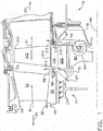
FIG. 1 , a cross-section of a portion of a turbine section 50 of a gas turbine engine is shown with aturbine blade 200 provided with an embodiment of anaft blade skirt 218. The portion of the shown turbine section 50 is a part of a two-stage high pressure turbine. The turbine 50 is disposed axially aft of theengine combustor 90, and axially forward of theengine nozzle 95. The shownturbine blade 200 is an embodiment of a secondstage turbine blade 200, and a plurality of theseturbine blades 200 are circumferentially disposed in a row about a radially distal section of acircular rotor 60. However, only oneturbine blade 200 is shown in this cross-section. - The
turbine blade 200 is provided with anairfoil 202, aplatform 204, ashank 206, and a fir-tree shapeddovetail 208. Theairfoil 202 extends from theplatform 204 radially distally and terminates in ablade tip 203. Theshank 206 extends radially proximally from theplatform 204, and thedovetail 208 extends radially proximally from theshank 206. Theturbine blade 200 attaches to arotor 60 via thedovetail 208. Theblade 200 is secured to therotor 60 via contact between an embodiment of ablade aft skirt 218 and aretainer 66, both of which are disposed on the aft side of theblade 200 androtor 60, respectively. Theretainer 66 may be fixed to therotor 60 via a lock ring andrabbet assembly 64. - Forward of the
turbine blade 200, a plurality ofnozzles 52 are circumferentially disposed. However, only onenozzle 52 is shown in this cross-section. Thenozzle 52 may also be referred to as a stator airfoil or stator vane. Eachnozzle 52 is secured to a stator case assembly 70, which defines a radially distal boundary of thegas flow 51 through the turbine 50, via a statorouter band 54. Thenozzle 52 is provided with a statorinner band 55 radially proximal of the statorouter band 54, meaning it is closer to alongitudinal axis 68 disposed through the gas turbine engine.Forward overlap bands 56 andaft overlap bands 58 are disposed on the statorinner band 55. Theaft overlap bands 58 overlap with the turbineforward angel wing 210. Theforward overlap bands 56 overlap with an aft angel wing of a forward turbine blade (not shown). - A
mid seal assembly 71 is also provided forward of theturbine blade 200, which rotates with therotor 60. Themid seal assembly 71 is provided with a retainer 72 for securing theturbine blade 200 on a forward side of therotor 60 as well as securing themid seal assembly 71 to therotor 60. - A first stage turbine blade assembly (not shown) may be provided forward of the
nozzle 52, and forward of and connected to themid seal assembly 71. - An inner stator assembly 74 may be disposed aft of the
turbine blade 200. This stator assembly 74 may be provided with a z-seal 76 that overlaps the turbine aft angel wings 212,214. -
Hot combustion gases 51 from theforward combustor 90 flow through an outer annular portion of the turbine section 50 past thenozzles 52 andturbine blades 200, then proceeding on to theengine nozzle 95. Theturbine blades 200 androtor 60 rotate as thehot gases 51 flow past theturbine blades 200.Cooler purge air 67 that has been bled from the compressor (not shown) and bypassed thecombustor 90 flows through a center portion of the turbine 50. Thepurge air 67 is at a higher pressure than the flow ofhot combustion gases 51 and will therefore leak into thatflow path 51 via gaps between thenozzles 52 andturbine blades 200. The overlapping interaction between theaft overlap bands 58 andforward angel wing 210, and between the turbineaft angel wings seal 76 control this leakage. -
FIG. 1 and the preceding text have been provided to describe a possible environment in which aturbine blade 200 provided with an embodiment of ablade skirt 218 of the present invention may be utilized. It is not intended to limit the description of the invention in any way. In addition, the environment and structure surrounding theblade skirt 218 embodiment may change depending on the overall design of the gas turbine engine in which it may be utilized, and where it is disposed within that engine. While the shownblade skirt 218 has been described on a secondstage turbine blade 200 in a high pressure turbine 50, it is to be understood that various embodiments of the skirt may be generally utilized on any blade used in a gas turbine engine. Furthermore, the following description of a turbine blade of theprior art 100 may be considered to exist in a similar surrounding structure as that depicted inFIG. 1 and the preceding description. - Referring now to
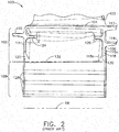
FIGS. 2-4 , a gasturbine engine blade 100 generally known in the prior art is depicted. Ablade 100 of the prior art typically possess a proximal end that mates with a rotor (not shown) and a distal end that terminates at a blade tip (not shown). The proximal end is radially inward of the distal end. Moving from the distal end to the proximal end, ablade 100 typically has anairfoil 102, aplatform 104, ashank 106, and amulti-lobe dovetail 108 having a fir tree configuration withmultiple dovetail lobes 128. These components are typically integrally joined. - A
blade 100 also typically possesses a forward side having aforward surface 130 that faces a stream of hot combustion gases coming from a combustion chamber (not shown) of the engine. Axially opposite from the forward side, the blade has an aft or suction side. On the forward side of theblade 100, there is aforward angel wing 110. The blade forward side may also be provided with aforward skirt 111 extending radially proximal from theforward angel wing 110 and generally blending with the blade forward surface. On the aft side of theblade 100, there is a distalaft angel wing 112 radially inward of that is a proximalaft angel wing 114 with a gap therebetween. Proximal of the aftproximal angel wing 114, there is afillet 116 that blends into askirt 118. - A
skirt 118 is disposed on the aft side of theblade 100. Theskirt 118 typically extends radially inward or proximally from the proximalaft angel wing 114 andfillet 116 and has aproximal edge 118a disposed distally of the upperminimum neck 132. Theskirt 118 also has anaft surface 118c. Theskirt 118 extends laterally across the aft side of theblade 100 and generally along an axially fixed plane perpendicular to a longitudinal axis of the engine. Theskirt 118, itsproximal edge 118a, and itsaft surface 118c blend into theshank 106, such that there is one lateral portion of the skirt and another lateral portion of the skirt on either side, or slash face of theshank 106. With this configuration, the skirt aftsurface 118c is interrupted by, or coincides with the blade aft surface. Accordingly, the blade aft surface is uninterrupted and generally flat from the tip of thedovetail 108 up to the proximalaft angel wing 114. On either lateral side of theshank 106, the skirtproximal end 118a blends into theshank 106 by askirt radius 120. A radially proximal end of theskirt radius 120 may terminate at or near an upperminimum neck 132. - A recess may be provided within the
shank portion 106 between the forward and aft sides of theblade 100. Within that recess, there is a forwarddamper retention lug 124 and anaft damper retention 126, which are used in conjunction with one another to retain a damper (not shown). Transitioning between theshank 106 anddovetail 108 is an upper minimum neck designated by dashedline 132. - The
dovetail section 108 is inserted in a rotor (not shown) such that thedovetail lobes 128 mate with the rotor to radially fix the blade in place. Aretainer 166 is fixedly attached to the rotor (not shown) in any known fashion, such as with a lock ring and rabbet feature. Theretainer 166 extends radially distal from the rotor and abuts theblade skirt 118 and blade aft surface so as to axially fix the blade along a longitudinal axis 168 of the engine. - Referring now to
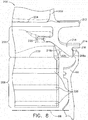
FIGS. 5-8 , an embodiment of ablade 200 of the present invention is depicted. Theblade 200 possesses a proximal end that mates with a rotor 60 (SeeFIG. 1 ) and a distal end that terminates at an airfoil tip 203 (SeeFIG. 1 ). The proximal end is radially inward of the distal end. One embodiment of a blade of the present invention has anairfoil 202 extending radially distal from aplatform 204, and ashank 206 extending radially proximal from theplatform 204. Amulti-lobe dovetail 208 having a fir tree configuration may extend from theshank 206 and terminate at a radially proximal end of theblade 200. These components is integrally joined together. - The
blade 200 also possess a forward side. Axially opposite from the forward side, theblade 200 has an aft or suction side. On the forward side of theblade 200, there is aforward angel wing 210. The blade forward side is also provided with aforward skirt 211 extending radially proximal from theforward angel wing 210 and generally blending with a bladeforward surface 230. On the aft side of theblade 200, there is a distalaft angel wing 212, and radially inward of that distalaft angel wing 212 anaft skirt 218. - The
aft skirt 218 extends axially aft of theshank 206, as well as radially proximally, such that theskirt 218 extends from theshank 206 at an angle and is proud of a blade aftsurface 234. A proximalaft angel wing 214 extends from a radially distal surface of theskirt 218. The proximalaft angel wing 214 andskirt 218 may be considered to be integrally formed, but this is not necessary. There may be a gap between the distalaft angel wing 212 and the proximalaft angel wing 214, which accommodates an overlap with a z-seal 76 (SeeFIG. 1 ) that may be aft of theturbine blade 200. - The
skirt 218, extending from theshank 206, terminates at anend 218a that, as described herein, is axially aft of theshank 206 and radially proximal of the proximalaft angel wing 214 and is also axially aft of theaft surface 234 of theblade 200. Theskirt end portion 218a and proximalaft angel wing 214 may be separated or, alternatively, blended together by afillet 216 or other transition surface. Theskirt end portion 218a possesses an appropriate geometry for mating with aretainer 66 as general described inFIG. 1 . - The
skirt 218 also possess aproximal surface 218b that extends from theshank 206 at an angle that is axially aft of theshank 206 and blade aftsurface 234. Askirt radius 220 serves as a transitioning surface between the skirtproximal surface 218b and theaft surface 234. Additionally, theskirt radius 220 may also serve as a transitioning surface between theaft surface 234 and a lateral side of theshank 206. Theskirt radius 220 may have a radially proximal end near or adjacent to an upperminimum neck 232. - As shown in
FIG. 7 , theskirt 218 may extend across theshank 206 and laterally from either side of theshank 206. Theskirt 218 may generally extend from one slash face of theblade 200 to the other slash face of theblade 200 generally uninterrupted. Theskirt 218 may also have a generally constant cross-sectional geometry across its entire lateral length. Accordingly, theskirt end portion 218a does not blend into the blade aftsurface 234. - A recess may be provided within the
shank portion 206 between the forward and aft sides of theblade 200. This recess may be bound by theforward skirt 211 theaft skirt 218 and the platform. Within that recess, there may be a forwarddamper retention lug 224 and an aftdamper retention lug 226, which are typically used in conjunction with one another to retain a damper (not shown). Transitioning between theshank 206 anddovetail 208 is an upper minimum neck designated by dashedline 232. - The
dovetail section 208 may be inserted in a rotor 60 (SeeFIG. 1 ) such that thedovetail lobes 228 mate with the rotor to radially fix the blade in place. Aretainer 66 is fixedly attached to the rotor 60 (SeeFIG. 1 ) in any known fashion, such as with a lock ring and rabbet assembly 64 (SeeFIG. 1 ). Theretainer 66 extends radially distal from the rotor and abuts theaft skirt 218 so as to axially fix theblade 200 along thelongitudinal axis 68 of the engine. - Referring now to
FIG. 9 , ablade 100 of the prior art is compared to ablade 200 of an embodiment of the present invention. The top surface of theplatform 204 of theblade 200 of the present invention is displayed level with the top of theplatform 104 of theblade 100 of the prior art. The aft features (for example, distalaft angel wings aft angel wing skirt 118, 218) of theblades minimum neck platform - As can be seen, the
aft skirt 218 of an embodiment of the present invention allows for a shorter stack of these aft features between the upperminimum neck 232 and theplatform 204 as compared to askirt 118 of the prior art. Thus, allowing for ashorter shank 206 as compared to ablade 100 of the prior art. This difference in size is shown bydimension 300, which spans the distance between the two upperminimum necks shorter shank portion 206 results in a reduced overall weight of a blade. It is believe that the total weight reduction of a typical blade may be 5% to 8%. However depending on design choices, this value may be greater or smaller. - A
blade 200 according to one embodiment of the present invention may require a slightlylonger retainer 66 as compared to a retainer of theprior art 166. However, the weight added to the retainer is substantially less than the weight reduced by thesmaller shank 206 afforded by an embodiment of ablade skirt 218 of the present invention. - The reduced blade weight may also result in less stress on the rotating components that hold the
blade 200, which improves their operational life and capabilities. Alternatively, rotor life may be maintained by reducing rotor sizes by removing material in components used in retaining theblade 200. This further reduces engine weight, which improves the overall efficiency of the turbine engine. - The foregoing description of structures and methods has been presented for purposes of illustration. It is not intended to be exhaustive or to limit the invention to the precise steps and/or forms disclosed, and obviously many modifications and variations are possible in light of the above teaching. Features described herein may be combined in any combination. Steps of a method described herein may be performed in any sequence that is physically possible. The blade described herein has been generically referred to as a blade. However, the same or similar features may be applied to either compressor or turbine blades of a gas turbine engine. It is understood that while certain forms of a blade skirt have been illustrated and described, it is not limited thereto and instead will only be limited by the claims, appended hereto.
Claims (4)
- A gas turbine engine blade (200) comprising:a proximal end and a radially opposite distal end, and a forward side and an axially opposite aft side;an airfoil (202), a platform (204), a shank (206), and a dovetail (208);wherein said airfoil (202) extends distally from said platform (204) and terminates at said distal end, said shank (206) extends proximally from said platform (204), and said dovetail (208) extends proximally from said shank (206) and terminates at said proximal end; and
a skirt (218) disposed at least partially on an aft side of said shank (206) and extending at least partially from said shank (206) in a direction that is at least partially axially aft of said shank (206) and at least partially radially toward said proximal end; wherein said skirt (218) has a first skirt surface (218b) that faces axially toward said forward side and also faces radially toward said proximal end, and said first skirt surface (218b) is disposed on a plane that is at an angle relative to an aft side surface of said shank (206);
wherein said first skirt surface (218b) and an aft side surface of said shank (206) have a skirt radius (220) disposed therebetween which serves as a transitioning surface between said first skirt surface (218b) and an aft surface (234) of said shank and also between said aft surface (234) of said shank and a lateral side of said shank; and
characterised in that
said skirt (218) comprises a skirt end portion 218a configured to mate with a retainer (66) for fixing the blade (200) to a rotor (60). - The gas turbine engine blade (200) of claim 1, further comprising a first lateral side and a laterally opposed second lateral side, wherein said skirt (218) extends laterally from said first lateral side to said second lateral side.
- The gas turbine engine blade (200) of claim 1 or claim 2, wherein said skirt end portion (218a) is extended away from and proud of said shank (206) and uninterrupted across a lateral dimension of said skirt (218).
- The gas turbine engine blade (200) of any preceding claim, wherein said skirt (218) has an end point at its radially proximal extreme that is disposed radially distal of a radially distal extreme of said dovetail (208).
Applications Claiming Priority (1)
| Application Number | Priority Date | Filing Date | Title |
|---|---|---|---|
| US13/306,413 US9039382B2 (en) | 2011-11-29 | 2011-11-29 | Blade skirt |
Publications (3)
| Publication Number | Publication Date |
|---|---|
| EP2599966A2 EP2599966A2 (en) | 2013-06-05 |
| EP2599966A3 EP2599966A3 (en) | 2014-06-11 |
| EP2599966B1 true EP2599966B1 (en) | 2017-02-22 |
Family
ID=47257618
Family Applications (1)
| Application Number | Title | Priority Date | Filing Date |
|---|---|---|---|
| EP12194394.8A Not-in-force EP2599966B1 (en) | 2011-11-29 | 2012-11-27 | Blade skirt |
Country Status (6)
| Country | Link |
|---|---|
| US (1) | US9039382B2 (en) |
| EP (1) | EP2599966B1 (en) |
| JP (1) | JP6114536B2 (en) |
| CN (1) | CN103133043B (en) |
| BR (1) | BR102012028875A2 (en) |
| CA (1) | CA2795653A1 (en) |
Families Citing this family (14)
| Publication number | Priority date | Publication date | Assignee | Title |
|---|---|---|---|---|
| GB2486488A (en) | 2010-12-17 | 2012-06-20 | Ge Aviat Systems Ltd | Testing a transient voltage protection device |
| US9039382B2 (en) * | 2011-11-29 | 2015-05-26 | General Electric Company | Blade skirt |
| EP2971555B1 (en) * | 2013-03-13 | 2021-04-28 | Raytheon Technologies Corporation | Rotor assembly with damper seal between blades |
| EP2881544A1 (en) * | 2013-12-09 | 2015-06-10 | Siemens Aktiengesellschaft | Airfoil device for a gas turbine and corresponding arrangement |
| US10563525B2 (en) * | 2013-12-19 | 2020-02-18 | United Technologies Corporation | Blade feature to support segmented coverplate |
| US11021976B2 (en) | 2014-12-22 | 2021-06-01 | Raytheon Technologies Corporation | Hardware geometry for increasing part overlap and maintaining clearance |
| US10807154B2 (en) | 2016-12-13 | 2020-10-20 | General Electric Company | Integrated casting core-shell structure for making cast component with cooling holes in inaccessible locations |
| US11813669B2 (en) | 2016-12-13 | 2023-11-14 | General Electric Company | Method for making an integrated core-shell structure |
| US20180161866A1 (en) | 2016-12-13 | 2018-06-14 | General Electric Company | Multi-piece integrated core-shell structure for making cast component |
| US20180161857A1 (en) | 2016-12-13 | 2018-06-14 | General Electric Company | Integrated casting core-shell structure for making cast components having thin root components |
| US10519785B2 (en) * | 2017-02-14 | 2019-12-31 | General Electric Company | Turbine blades having damper pin slot features and methods of fabricating the same |
| CN108504888B (en) * | 2018-04-08 | 2020-10-27 | 昆明理工大学 | Preparation method of ceramic composite ball reinforced metal matrix composite material |
| GB202114772D0 (en) * | 2021-10-15 | 2021-12-01 | Rolls Royce Plc | Bladed disc |
| GB202114773D0 (en) * | 2021-10-15 | 2021-12-01 | Rolls Royce Plc | Bladed disc |
Citations (1)
| Publication number | Priority date | Publication date | Assignee | Title |
|---|---|---|---|---|
| GB2409240A (en) * | 2003-12-18 | 2005-06-22 | Rolls Royce Plc | Cooling arrangement |
Family Cites Families (37)
| Publication number | Priority date | Publication date | Assignee | Title |
|---|---|---|---|---|
| FR2524932A1 (en) * | 1982-04-08 | 1983-10-14 | Snecma | DEVICE FOR AXIAL RETENTION OF BLADE FEET IN A TURBOMACHINE DISC |
| US4480958A (en) | 1983-02-09 | 1984-11-06 | The United States Of America As Represented By The Secretary Of The Air Force | High pressure turbine rotor two-piece blade retainer |
| US5183389A (en) | 1992-01-30 | 1993-02-02 | General Electric Company | Anti-rock blade tang |
| US5302085A (en) | 1992-02-03 | 1994-04-12 | General Electric Company | Turbine blade damper |
| US5261790A (en) | 1992-02-03 | 1993-11-16 | General Electric Company | Retention device for turbine blade damper |
| US5257909A (en) | 1992-08-17 | 1993-11-02 | General Electric Company | Dovetail sealing device for axial dovetail rotor blades |
| US5302086A (en) | 1992-08-18 | 1994-04-12 | General Electric Company | Apparatus for retaining rotor blades |
| WO1996006266A1 (en) * | 1994-08-24 | 1996-02-29 | Westinghouse Electric Corporation | Gas turbine blade with cooled platform |
| GB2455431B (en) * | 1994-11-30 | 2009-11-18 | Rolls Royce Plc | Split shank rotor blade |
| US6354803B1 (en) | 2000-06-30 | 2002-03-12 | General Electric Company | Blade damper and method for making same |
| US6769865B2 (en) | 2002-03-22 | 2004-08-03 | General Electric Company | Band cooled turbine nozzle |
| US6857853B1 (en) | 2003-08-13 | 2005-02-22 | General Electric Company | Conical tip shroud fillet for a turbine bucket |
| US6923616B2 (en) | 2003-09-02 | 2005-08-02 | General Electric Company | Methods and apparatus for cooling gas turbine engine rotor assemblies |
| US7147440B2 (en) | 2003-10-31 | 2006-12-12 | General Electric Company | Methods and apparatus for cooling gas turbine engine rotor assemblies |
| US6984112B2 (en) | 2003-10-31 | 2006-01-10 | General Electric Company | Methods and apparatus for cooling gas turbine rotor blades |
| US7600972B2 (en) | 2003-10-31 | 2009-10-13 | General Electric Company | Methods and apparatus for cooling gas turbine engine rotor assemblies |
| US7238008B2 (en) | 2004-05-28 | 2007-07-03 | General Electric Company | Turbine blade retainer seal |
| US7097429B2 (en) | 2004-07-13 | 2006-08-29 | General Electric Company | Skirted turbine blade |
| US7131817B2 (en) | 2004-07-30 | 2006-11-07 | General Electric Company | Method and apparatus for cooling gas turbine engine rotor blades |
| US7144215B2 (en) | 2004-07-30 | 2006-12-05 | General Electric Company | Method and apparatus for cooling gas turbine engine rotor blades |
| US7198467B2 (en) | 2004-07-30 | 2007-04-03 | General Electric Company | Method and apparatus for cooling gas turbine engine rotor blades |
| US7189063B2 (en) | 2004-09-02 | 2007-03-13 | General Electric Company | Methods and apparatus for cooling gas turbine engine rotor assemblies |
| US7090466B2 (en) | 2004-09-14 | 2006-08-15 | General Electric Company | Methods and apparatus for assembling gas turbine engine rotor assemblies |
| US7244101B2 (en) * | 2005-10-04 | 2007-07-17 | General Electric Company | Dust resistant platform blade |
| US7322797B2 (en) * | 2005-12-08 | 2008-01-29 | General Electric Company | Damper cooled turbine blade |
| US7731482B2 (en) * | 2006-06-13 | 2010-06-08 | General Electric Company | Bucket vibration damper system |
| EP1914386A1 (en) * | 2006-10-17 | 2008-04-23 | Siemens Aktiengesellschaft | Turbine blade assembly |
| US7762780B2 (en) * | 2007-01-25 | 2010-07-27 | Siemens Energy, Inc. | Blade assembly in a combustion turbo-machine providing reduced concentration of mechanical stress and a seal between adjacent assemblies |
| EP2053285A1 (en) | 2007-10-25 | 2009-04-29 | Siemens Aktiengesellschaft | Turbine blade assembly |
| BRPI0818386A2 (en) * | 2007-10-25 | 2015-04-22 | Siemens Ag | Turbine blade assembly and sealing strip |
| JP5091745B2 (en) | 2008-03-31 | 2012-12-05 | 三菱重工業株式会社 | Turbine blade mating structure |
| JP5173625B2 (en) * | 2008-06-20 | 2013-04-03 | 三菱重工業株式会社 | Rotor blade and gas turbine |
| US8573942B2 (en) * | 2008-11-25 | 2013-11-05 | Alstom Technology Ltd. | Axial retention of a platform seal |
| US8382436B2 (en) * | 2009-01-06 | 2013-02-26 | General Electric Company | Non-integral turbine blade platforms and systems |
| US8083475B2 (en) * | 2009-01-13 | 2011-12-27 | General Electric Company | Turbine bucket angel wing compression seal |
| US9039382B2 (en) * | 2011-11-29 | 2015-05-26 | General Electric Company | Blade skirt |
| FR3003893B1 (en) * | 2013-04-02 | 2017-12-29 | Snecma | TURBINE DAWN |
-
2011
- 2011-11-29 US US13/306,413 patent/US9039382B2/en active Active
-
2012
- 2012-11-12 BR BR102012028875A patent/BR102012028875A2/en not_active IP Right Cessation
- 2012-11-15 CA CA 2795653 patent/CA2795653A1/en not_active Abandoned
- 2012-11-20 JP JP2012253799A patent/JP6114536B2/en not_active Expired - Fee Related
- 2012-11-27 EP EP12194394.8A patent/EP2599966B1/en not_active Not-in-force
- 2012-11-28 CN CN201210493673.6A patent/CN103133043B/en active Active
Patent Citations (1)
| Publication number | Priority date | Publication date | Assignee | Title |
|---|---|---|---|---|
| GB2409240A (en) * | 2003-12-18 | 2005-06-22 | Rolls Royce Plc | Cooling arrangement |
Also Published As
| Publication number | Publication date |
|---|---|
| CN103133043A (en) | 2013-06-05 |
| CA2795653A1 (en) | 2013-05-29 |
| EP2599966A2 (en) | 2013-06-05 |
| US9039382B2 (en) | 2015-05-26 |
| US20130136618A1 (en) | 2013-05-30 |
| CN103133043B (en) | 2016-06-08 |
| JP6114536B2 (en) | 2017-04-12 |
| EP2599966A3 (en) | 2014-06-11 |
| BR102012028875A2 (en) | 2015-11-03 |
| JP2013113298A (en) | 2013-06-10 |
Similar Documents
| Publication | Publication Date | Title |
|---|---|---|
| EP2599966B1 (en) | Blade skirt | |
| US7090466B2 (en) | Methods and apparatus for assembling gas turbine engine rotor assemblies | |
| CN107435561B (en) | System for cooling seal rails of tip shroud of turbine blade | |
| US8105039B1 (en) | Airfoil tip shroud damper | |
| US9816393B2 (en) | Turbine blade and turbine with improved sealing | |
| EP1605137B1 (en) | Cooled rotor blade | |
| EP2978938B1 (en) | Turbine engine assembly with l-shaped feather seal | |
| EP3091190B1 (en) | Component, corresponding gas turbine engine and sealing method | |
| EP3314093B1 (en) | Shrouded turbine blade | |
| EP2948642B1 (en) | Multi-segment adjustable stator vane for a variable area vane arrangement | |
| US9909435B2 (en) | Turbine engine variable area vane with feather seal | |
| EP2971553A1 (en) | Rotor blade with a conic spline fillet at an intersection between a platform and a neck | |
| US20170306768A1 (en) | Turbine engine shroud assembly | |
| US20170356298A1 (en) | Stator vane | |
| US20180179901A1 (en) | Turbine blade with contoured tip shroud | |
| US20120156045A1 (en) | Methods, systems and apparatus relating to root and platform configurations for turbine rotor blades | |
| US8764387B2 (en) | Aggregate vane assembly | |
| CN111058899B (en) | Rotor assembly with rotor disk lip | |
| EP3594450A1 (en) | Blade for a gas turbine engine | |
| WO2017200549A1 (en) | Tip shroud with a fence feature for discouraging pitch-wise over-tip leakage flow | |
| EP4144959A1 (en) | Fluid machine for an aircraft engine and aircraft engine | |
| US11585229B2 (en) | Bladed disk flexible in the lower part of the blades |
Legal Events
| Date | Code | Title | Description |
|---|---|---|---|
| PUAI | Public reference made under article 153(3) epc to a published international application that has entered the european phase |
Free format text: ORIGINAL CODE: 0009012 |
|
| AK | Designated contracting states |
Kind code of ref document: A2 Designated state(s): AL AT BE BG CH CY CZ DE DK EE ES FI FR GB GR HR HU IE IS IT LI LT LU LV MC MK MT NL NO PL PT RO RS SE SI SK SM TR |
|
| AX | Request for extension of the european patent |
Extension state: BA ME |
|
| PUAL | Search report despatched |
Free format text: ORIGINAL CODE: 0009013 |
|
| AK | Designated contracting states |
Kind code of ref document: A3 Designated state(s): AL AT BE BG CH CY CZ DE DK EE ES FI FR GB GR HR HU IE IS IT LI LT LU LV MC MK MT NL NO PL PT RO RS SE SI SK SM TR |
|
| AX | Request for extension of the european patent |
Extension state: BA ME |
|
| RIC1 | Information provided on ipc code assigned before grant |
Ipc: F01D 11/00 20060101AFI20140508BHEP Ipc: F01D 5/30 20060101ALI20140508BHEP |
|
| 17P | Request for examination filed |
Effective date: 20141211 |
|
| RBV | Designated contracting states (corrected) |
Designated state(s): AL AT BE BG CH CY CZ DE DK EE ES FI FR GB GR HR HU IE IS IT LI LT LU LV MC MK MT NL NO PL PT RO RS SE SI SK SM TR |
|
| 17Q | First examination report despatched |
Effective date: 20150709 |
|
| REG | Reference to a national code |
Ref country code: DE Ref legal event code: R079 Ref document number: 602012028883 Country of ref document: DE Free format text: PREVIOUS MAIN CLASS: F01D0011000000 Ipc: F01D0005140000 |
|
| RIC1 | Information provided on ipc code assigned before grant |
Ipc: F01D 11/00 20060101ALI20160826BHEP Ipc: F01D 5/30 20060101ALI20160826BHEP Ipc: F01D 5/14 20060101AFI20160826BHEP |
|
| GRAP | Despatch of communication of intention to grant a patent |
Free format text: ORIGINAL CODE: EPIDOSNIGR1 |
|
| INTG | Intention to grant announced |
Effective date: 20161010 |
|
| GRAS | Grant fee paid |
Free format text: ORIGINAL CODE: EPIDOSNIGR3 |
|
| GRAA | (expected) grant |
Free format text: ORIGINAL CODE: 0009210 |
|
| AK | Designated contracting states |
Kind code of ref document: B1 Designated state(s): AL AT BE BG CH CY CZ DE DK EE ES FI FR GB GR HR HU IE IS IT LI LT LU LV MC MK MT NL NO PL PT RO RS SE SI SK SM TR |
|
| REG | Reference to a national code |
Ref country code: GB Ref legal event code: FG4D |
|
| REG | Reference to a national code |
Ref country code: CH Ref legal event code: EP |
|
| REG | Reference to a national code |
Ref country code: AT Ref legal event code: REF Ref document number: 869444 Country of ref document: AT Kind code of ref document: T Effective date: 20170315 |
|
| REG | Reference to a national code |
Ref country code: IE Ref legal event code: FG4D |
|
| REG | Reference to a national code |
Ref country code: DE Ref legal event code: R096 Ref document number: 602012028883 Country of ref document: DE |
|
| REG | Reference to a national code |
Ref country code: LT Ref legal event code: MG4D |
|
| REG | Reference to a national code |
Ref country code: NL Ref legal event code: MP Effective date: 20170222 |
|
| REG | Reference to a national code |
Ref country code: AT Ref legal event code: MK05 Ref document number: 869444 Country of ref document: AT Kind code of ref document: T Effective date: 20170222 |
|
| PG25 | Lapsed in a contracting state [announced via postgrant information from national office to epo] |
Ref country code: NO Free format text: LAPSE BECAUSE OF FAILURE TO SUBMIT A TRANSLATION OF THE DESCRIPTION OR TO PAY THE FEE WITHIN THE PRESCRIBED TIME-LIMIT Effective date: 20170522 Ref country code: HR Free format text: LAPSE BECAUSE OF FAILURE TO SUBMIT A TRANSLATION OF THE DESCRIPTION OR TO PAY THE FEE WITHIN THE PRESCRIBED TIME-LIMIT Effective date: 20170222 Ref country code: GR Free format text: LAPSE BECAUSE OF FAILURE TO SUBMIT A TRANSLATION OF THE DESCRIPTION OR TO PAY THE FEE WITHIN THE PRESCRIBED TIME-LIMIT Effective date: 20170523 Ref country code: FI Free format text: LAPSE BECAUSE OF FAILURE TO SUBMIT A TRANSLATION OF THE DESCRIPTION OR TO PAY THE FEE WITHIN THE PRESCRIBED TIME-LIMIT Effective date: 20170222 Ref country code: LT Free format text: LAPSE BECAUSE OF FAILURE TO SUBMIT A TRANSLATION OF THE DESCRIPTION OR TO PAY THE FEE WITHIN THE PRESCRIBED TIME-LIMIT Effective date: 20170222 |
|
| PG25 | Lapsed in a contracting state [announced via postgrant information from national office to epo] |
Ref country code: LV Free format text: LAPSE BECAUSE OF FAILURE TO SUBMIT A TRANSLATION OF THE DESCRIPTION OR TO PAY THE FEE WITHIN THE PRESCRIBED TIME-LIMIT Effective date: 20170222 Ref country code: ES Free format text: LAPSE BECAUSE OF FAILURE TO SUBMIT A TRANSLATION OF THE DESCRIPTION OR TO PAY THE FEE WITHIN THE PRESCRIBED TIME-LIMIT Effective date: 20170222 Ref country code: AT Free format text: LAPSE BECAUSE OF FAILURE TO SUBMIT A TRANSLATION OF THE DESCRIPTION OR TO PAY THE FEE WITHIN THE PRESCRIBED TIME-LIMIT Effective date: 20170222 Ref country code: NL Free format text: LAPSE BECAUSE OF FAILURE TO SUBMIT A TRANSLATION OF THE DESCRIPTION OR TO PAY THE FEE WITHIN THE PRESCRIBED TIME-LIMIT Effective date: 20170222 Ref country code: SE Free format text: LAPSE BECAUSE OF FAILURE TO SUBMIT A TRANSLATION OF THE DESCRIPTION OR TO PAY THE FEE WITHIN THE PRESCRIBED TIME-LIMIT Effective date: 20170222 Ref country code: RS Free format text: LAPSE BECAUSE OF FAILURE TO SUBMIT A TRANSLATION OF THE DESCRIPTION OR TO PAY THE FEE WITHIN THE PRESCRIBED TIME-LIMIT Effective date: 20170222 Ref country code: BG Free format text: LAPSE BECAUSE OF FAILURE TO SUBMIT A TRANSLATION OF THE DESCRIPTION OR TO PAY THE FEE WITHIN THE PRESCRIBED TIME-LIMIT Effective date: 20170522 Ref country code: PT Free format text: LAPSE BECAUSE OF FAILURE TO SUBMIT A TRANSLATION OF THE DESCRIPTION OR TO PAY THE FEE WITHIN THE PRESCRIBED TIME-LIMIT Effective date: 20170622 |
|
| PG25 | Lapsed in a contracting state [announced via postgrant information from national office to epo] |
Ref country code: SK Free format text: LAPSE BECAUSE OF FAILURE TO SUBMIT A TRANSLATION OF THE DESCRIPTION OR TO PAY THE FEE WITHIN THE PRESCRIBED TIME-LIMIT Effective date: 20170222 Ref country code: CZ Free format text: LAPSE BECAUSE OF FAILURE TO SUBMIT A TRANSLATION OF THE DESCRIPTION OR TO PAY THE FEE WITHIN THE PRESCRIBED TIME-LIMIT Effective date: 20170222 Ref country code: IT Free format text: LAPSE BECAUSE OF FAILURE TO SUBMIT A TRANSLATION OF THE DESCRIPTION OR TO PAY THE FEE WITHIN THE PRESCRIBED TIME-LIMIT Effective date: 20170222 Ref country code: EE Free format text: LAPSE BECAUSE OF FAILURE TO SUBMIT A TRANSLATION OF THE DESCRIPTION OR TO PAY THE FEE WITHIN THE PRESCRIBED TIME-LIMIT Effective date: 20170222 Ref country code: RO Free format text: LAPSE BECAUSE OF FAILURE TO SUBMIT A TRANSLATION OF THE DESCRIPTION OR TO PAY THE FEE WITHIN THE PRESCRIBED TIME-LIMIT Effective date: 20170222 |
|
| REG | Reference to a national code |
Ref country code: DE Ref legal event code: R097 Ref document number: 602012028883 Country of ref document: DE |
|
| PG25 | Lapsed in a contracting state [announced via postgrant information from national office to epo] |
Ref country code: DK Free format text: LAPSE BECAUSE OF FAILURE TO SUBMIT A TRANSLATION OF THE DESCRIPTION OR TO PAY THE FEE WITHIN THE PRESCRIBED TIME-LIMIT Effective date: 20170222 Ref country code: SM Free format text: LAPSE BECAUSE OF FAILURE TO SUBMIT A TRANSLATION OF THE DESCRIPTION OR TO PAY THE FEE WITHIN THE PRESCRIBED TIME-LIMIT Effective date: 20170222 Ref country code: PL Free format text: LAPSE BECAUSE OF FAILURE TO SUBMIT A TRANSLATION OF THE DESCRIPTION OR TO PAY THE FEE WITHIN THE PRESCRIBED TIME-LIMIT Effective date: 20170222 |
|
| PLBE | No opposition filed within time limit |
Free format text: ORIGINAL CODE: 0009261 |
|
| STAA | Information on the status of an ep patent application or granted ep patent |
Free format text: STATUS: NO OPPOSITION FILED WITHIN TIME LIMIT |
|
| 26N | No opposition filed |
Effective date: 20171123 |
|
| PG25 | Lapsed in a contracting state [announced via postgrant information from national office to epo] |
Ref country code: SI Free format text: LAPSE BECAUSE OF FAILURE TO SUBMIT A TRANSLATION OF THE DESCRIPTION OR TO PAY THE FEE WITHIN THE PRESCRIBED TIME-LIMIT Effective date: 20170222 |
|
| REG | Reference to a national code |
Ref country code: DE Ref legal event code: R119 Ref document number: 602012028883 Country of ref document: DE |
|
| PG25 | Lapsed in a contracting state [announced via postgrant information from national office to epo] |
Ref country code: MC Free format text: LAPSE BECAUSE OF FAILURE TO SUBMIT A TRANSLATION OF THE DESCRIPTION OR TO PAY THE FEE WITHIN THE PRESCRIBED TIME-LIMIT Effective date: 20170222 |
|
| GBPC | Gb: european patent ceased through non-payment of renewal fee |
Effective date: 20171127 |
|
| PG25 | Lapsed in a contracting state [announced via postgrant information from national office to epo] |
Ref country code: CH Free format text: LAPSE BECAUSE OF NON-PAYMENT OF DUE FEES Effective date: 20171130 Ref country code: LI Free format text: LAPSE BECAUSE OF NON-PAYMENT OF DUE FEES Effective date: 20171130 |
|
| PG25 | Lapsed in a contracting state [announced via postgrant information from national office to epo] |
Ref country code: LU Free format text: LAPSE BECAUSE OF NON-PAYMENT OF DUE FEES Effective date: 20171127 |
|
| REG | Reference to a national code |
Ref country code: FR Ref legal event code: ST Effective date: 20180731 Ref country code: BE Ref legal event code: MM Effective date: 20171130 |
|
| REG | Reference to a national code |
Ref country code: IE Ref legal event code: MM4A |
|
| PG25 | Lapsed in a contracting state [announced via postgrant information from national office to epo] |
Ref country code: MT Free format text: LAPSE BECAUSE OF NON-PAYMENT OF DUE FEES Effective date: 20171127 |
|
| PG25 | Lapsed in a contracting state [announced via postgrant information from national office to epo] |
Ref country code: IE Free format text: LAPSE BECAUSE OF NON-PAYMENT OF DUE FEES Effective date: 20171127 Ref country code: FR Free format text: LAPSE BECAUSE OF NON-PAYMENT OF DUE FEES Effective date: 20171130 Ref country code: DE Free format text: LAPSE BECAUSE OF NON-PAYMENT OF DUE FEES Effective date: 20180602 |
|
| PG25 | Lapsed in a contracting state [announced via postgrant information from national office to epo] |
Ref country code: BE Free format text: LAPSE BECAUSE OF NON-PAYMENT OF DUE FEES Effective date: 20171130 Ref country code: GB Free format text: LAPSE BECAUSE OF NON-PAYMENT OF DUE FEES Effective date: 20171127 |
|
| PG25 | Lapsed in a contracting state [announced via postgrant information from national office to epo] |
Ref country code: HU Free format text: LAPSE BECAUSE OF FAILURE TO SUBMIT A TRANSLATION OF THE DESCRIPTION OR TO PAY THE FEE WITHIN THE PRESCRIBED TIME-LIMIT; INVALID AB INITIO Effective date: 20121127 |
|
| PG25 | Lapsed in a contracting state [announced via postgrant information from national office to epo] |
Ref country code: CY Free format text: LAPSE BECAUSE OF NON-PAYMENT OF DUE FEES Effective date: 20170222 |
|
| PG25 | Lapsed in a contracting state [announced via postgrant information from national office to epo] |
Ref country code: MK Free format text: LAPSE BECAUSE OF FAILURE TO SUBMIT A TRANSLATION OF THE DESCRIPTION OR TO PAY THE FEE WITHIN THE PRESCRIBED TIME-LIMIT Effective date: 20170222 |
|
| PG25 | Lapsed in a contracting state [announced via postgrant information from national office to epo] |
Ref country code: TR Free format text: LAPSE BECAUSE OF FAILURE TO SUBMIT A TRANSLATION OF THE DESCRIPTION OR TO PAY THE FEE WITHIN THE PRESCRIBED TIME-LIMIT Effective date: 20170222 |
|
| PG25 | Lapsed in a contracting state [announced via postgrant information from national office to epo] |
Ref country code: AL Free format text: LAPSE BECAUSE OF FAILURE TO SUBMIT A TRANSLATION OF THE DESCRIPTION OR TO PAY THE FEE WITHIN THE PRESCRIBED TIME-LIMIT Effective date: 20170222 Ref country code: IS Free format text: LAPSE BECAUSE OF FAILURE TO SUBMIT A TRANSLATION OF THE DESCRIPTION OR TO PAY THE FEE WITHIN THE PRESCRIBED TIME-LIMIT Effective date: 20170622 |