EP1605137B1 - Cooled rotor blade - Google Patents
Cooled rotor blade Download PDFInfo
- Publication number
- EP1605137B1 EP1605137B1 EP05253260A EP05253260A EP1605137B1 EP 1605137 B1 EP1605137 B1 EP 1605137B1 EP 05253260 A EP05253260 A EP 05253260A EP 05253260 A EP05253260 A EP 05253260A EP 1605137 B1 EP1605137 B1 EP 1605137B1
- Authority
- EP
- European Patent Office
- Prior art keywords
- conduit
- inlet
- mid
- leading edge
- centerline
- Prior art date
- Legal status (The legal status is an assumption and is not a legal conclusion. Google has not performed a legal analysis and makes no representation as to the accuracy of the status listed.)
- Expired - Lifetime
Links
Images
Classifications
-
- F—MECHANICAL ENGINEERING; LIGHTING; HEATING; WEAPONS; BLASTING
- F01—MACHINES OR ENGINES IN GENERAL; ENGINE PLANTS IN GENERAL; STEAM ENGINES
- F01D—NON-POSITIVE DISPLACEMENT MACHINES OR ENGINES, e.g. STEAM TURBINES
- F01D5/00—Blades; Blade-carrying members; Heating, heat-insulating, cooling or antivibration means on the blades or the members
- F01D5/30—Fixing blades to rotors; Blade roots ; Blade spacers
- F01D5/3007—Fixing blades to rotors; Blade roots ; Blade spacers of axial insertion type
-
- F—MECHANICAL ENGINEERING; LIGHTING; HEATING; WEAPONS; BLASTING
- F01—MACHINES OR ENGINES IN GENERAL; ENGINE PLANTS IN GENERAL; STEAM ENGINES
- F01D—NON-POSITIVE DISPLACEMENT MACHINES OR ENGINES, e.g. STEAM TURBINES
- F01D5/00—Blades; Blade-carrying members; Heating, heat-insulating, cooling or antivibration means on the blades or the members
- F01D5/02—Blade-carrying members, e.g. rotors
- F01D5/08—Heating, heat-insulating or cooling means
- F01D5/081—Cooling fluid being directed on the side of the rotor disc or at the roots of the blades
-
- F—MECHANICAL ENGINEERING; LIGHTING; HEATING; WEAPONS; BLASTING
- F01—MACHINES OR ENGINES IN GENERAL; ENGINE PLANTS IN GENERAL; STEAM ENGINES
- F01D—NON-POSITIVE DISPLACEMENT MACHINES OR ENGINES, e.g. STEAM TURBINES
- F01D5/00—Blades; Blade-carrying members; Heating, heat-insulating, cooling or antivibration means on the blades or the members
- F01D5/12—Blades
- F01D5/14—Form or construction
- F01D5/18—Hollow blades, i.e. blades with cooling or heating channels or cavities; Heating, heat-insulating or cooling means on blades
- F01D5/187—Convection cooling
Definitions
- This invention applies to gas turbine rotor blades in general, and to cooled gas turbine rotor blades in particular.
- Turbine sections within an axial flow turbine engine include rotor assemblies that include a disc and a number of rotor blades.
- the disk includes a plurality of recesses circumferentially disposed around the disk for receiving the blades.
- Each blade includes a root, a hollow airfoil, and a platform.
- the root includes conduits through which cooling air may enter the blade and pass through into a cavity within the hollow airfoil.
- the blade roots and recesses are shaped (e.g., a fir tree configuration) to mate with one another to retain the blades to the disk.
- the mating geometries create a predetermined gap between the base of each recess and the base of the blade root. The gap enables cooling air to enter the recess and pass into the blade root.
- Airflow pressure differences propel cooling air into and out of the rotor blade.
- Relatively high pressure cooling air is typically bled off of a compressor section.
- the energy imparted to that air enables the requisite cooling, but does so at a cost since that energy is no longer available to create thrust within the engine.
- the gas path pressure external to a rotor blade airfoil is highest at the leading edge region during operation of the blade.
- airfoils are typically backflow margin limited at the leading edge of the airfoil.
- backflow margin refers to the ratio of internal pressure to external pressure. To ensure hot gases from the external gas path do not flow into an airfoil, it is necessary to maintain a particular predetermined backflow margin that accounts for expected internal and external pressure variations. Hence, it is desirable to minimize pressure drops within the airfoil to the extent possible, particularly with respect to passages providing airflow to cool the leading edge.
- conduits within a blade root having a bellmouth inlet i.e., an inlet that is flared on the leading edge ("forward") side, suction side, pressure side, and the trailing edge (“ aft") side.
- a disadvantage of this approach is that the bellmouth inlet decreases the size of the root material that extends between the suction side and pressure side, between adjacent conduits.
- the blade root is highly loaded between the suction and pressure sides. Decreasing the cross-sectional area of root material between the suction and pressure sides undesirably decreases the ability of the root to handle the load.
- a rotor blade that requires less energy to be adequately cooled relative to prior art rotor blades, one that requires less energy for cooling by reducing pressure losses within the rotor blade relative to prior art rotor blades, and one that can adequately handle the attachment loading within the root.
- rotor blades are provided as claimed in claims 1, 3, 5 and 9.
- Another advantage of the present invention is that airflow pressure losses are achieved without compromising blade root load capability.
- Prior art root conduits having bellmouth inlets decreased the pressure loss for cooling air entering the root conduits, but did so at the expense of blade root load capability.
- the present invention provides the advantageous flow characteristics without appreciably negatively affecting the blade root load capability.
- a rotor blade assembly 10 for a gas turbine engine having a disk 12 and a plurality of rotor blades 14.
- the disk 12 includes a plurality of recesses 16 circumferentially disposed around the disk 12 and a rotational centerline 18 about which the disk 12 may rotate.
- Each blade 14 includes a root 20, an airfoil 22, a platform 24, and a radial centerline 25.
- the root 20 includes a geometry (e.g., a fir tree configuration) that mates with that of one of the recesses 16 within the disk 12.
- the airfoil 22 includes a base 28, a tip 30, a leading edge 32, a trailing edge 34, a pressure-side wall 36 (see FIG. 1), and a suction-side wall 38 (see FIG. 1), and a cavity 40.
- FIG. 2 diagrammatically illustrates an airfoil 22 sectioned between the leading edge 32 and the trailing edge 34.
- the pressure-side wall 36 and the suction-side wall 38 extend between the base 28 and the tip 30 and meet at the leading edge 32 and the trailing edge 34.
- the root 20 has a leading edge conduit 42, at least one mid-body conduit 44, and a trailing edge conduit 46.
- the conduits 42, 44, 46 are operable to permit airflow through the root 20 and into the cavity 40.
- Each conduit 42, 44, 46 has a centerline 58,74,88.
- the leading edge conduit 42 includes an inlet 48 having a forward side 50, an aft side 52, a suction side 54, and a pressure side 56.
- the forward, suction, and pressure sides 50, 54, 56 each diverge from the centerline 58 of the leading edge conduit 42.
- the forward side 50 diverges at a different angle than the suction and pressure sides 54, 56.
- the forward side 50 diverges at a greater angle than the suction and pressure sides 54, 56.
- the aft side 52 is substantially parallel to the centerline 58 of the leading edge conduit 42 (FIG. 3).
- the aft side 52 converges toward the leading edge end 60 of the root 20 (FIG. 4).
- the aft side 52 is diagrammatically shown as substantially parallel to the forward side 50.
- the leading edge conduit 42 is in fluid communication with one or more leading edge passages 62 disposed within the cavity 40, adjacent the leading edge 32 of the airfoil 22.
- the leading edge conduit 42 provides the primary path into the leading edge passage(s) 62 for cooling air, and therefore the airfoil leading edge 32 is primarily cooled by the cooling air that enters the airfoil 22 through the leading edge conduit 42.
- the mid-body conduit(s) 44 includes an inlet 64 having a suction side 66, a pressure side 68, an aft side 70, and a forward side 72.
- the suction and pressure sides 66, 68 each diverge from the centerline 74 of the mid-body conduit 44.
- the aft and forward sides 70, 72 are substantially parallel to the centerline 74 of the mid-body conduit 44 (FIG. 3).
- the forward side 72 diverges toward the leading edge end 60 of the root 20 (FIG. 4).
- the forward side 72 of the mid -body conduit 44 is shown as substantially parallel to the aft side 52 of the leading edge conduit 42.
- the mid-body conduit(s) 44 is in fluid communication with one or more mid-body passages 76 disposed within the cavity 40.
- the mid-body conduit 44 provides the primary path into the mid-body passages 76 for cooling air, and therefore the airfoil 22 mid-body region is primarily cooled by the cooling air that enters the airfoil 22 through the mid -body conduit 44.
- the trailing edge conduit 46 includes an inlet 78 having an aft side 80, a forward side 82, a suction side 84, and a pressure side 86.
- the suction and pressure sides 84, 86 each diverge from the centerline 88 of the trailing edge conduit 46.
- the aft and forward sides 80, 82 are substantially parallel to the centerline 88 of the trailing edge conduit 46 (e.g., FIGS. 3 and 4).
- the aft side 80 diverges from the centerline 88 of the trailing edge conduit 46
- the trailing edge conduit 46 is in fluid communication with one or more passages 90 disposed within the cavity 40, adjacent the trailing edge 34 of the airfoil 22.
- the trailing edge conduit 46 provides the primary path into the passages 90 for cooling air. Consequently, the trailing edge 34 is primarily cooled by cooling air that enters the airfoil 22 through the trailing edge conduit 46.
- Cooling air 91 enters the gap 92 between the blade root 20 and base 94 of the recess 16, traveling in a direction that is approximately perpendicular to the radial centerline 25 of the blade 14.
- the cooling airflow 91 first encounters the leading edge end 60 of the root 20, and subsequently the leading edge conduit 42.
- the forward side 50 of the leading edge conduit 42 facilitates the transition of cooling airflow into the leading edge conduit 42, and thereby lowers the pressure drop associated with the turn in cooling airflow relative to that which would be associated, for example, with a 90° turn.
- the divergent suction and pressure sides 54, 56 open the inlet 48 to facilitate cooling airflow entry from the sides.
- the divergent suction and pressure sides 66, 68 open the inlet 64 to facilitate cooling airflow entry from the sides, and to decrease the pressure drop for cooling airflow turning into the inlet 46 from the sides.
- the inlet 64 forward side 72 facilitates the transition of cooling airflow into the mid-body conduit 44 as described above. Both embodiments of the forward side 72 do not decrease the cross-sectional area of the root portion 96 disposed between the leading edge conduit 42 and the mid-body conduit 44. Consequently, the blade root load capability is not negatively affected, as would be the case if the leading edge and mid-body conduit inlets 48, 64 flared toward one another.
- the divergent suction and pressure sides 84, 86 open the inlet to facilitate cooling airflow entry from the sides, and to decrease the pressure drop for cooling airflow turning into the inlet 78 from the sides.
- the inlet forward side 82 facilitates the transition of cooling airflow into the trailing edge conduit 46 as described above.
- Both embodiments of the trailing edge conduit forward side 82 do not decrease the cross-sectional area of the root portion 98 extending between the mid-body conduit 44 and the trailing edge conduit 46. Consequently, the blade root load capability is not negatively affected, as would be the case if mid-body and trailing edge conduit inlets 64, 78 flared toward one another.
Landscapes
- Engineering & Computer Science (AREA)
- Mechanical Engineering (AREA)
- General Engineering & Computer Science (AREA)
- Turbine Rotor Nozzle Sealing (AREA)
Description
- This invention applies to gas turbine rotor blades in general, and to cooled gas turbine rotor blades in particular.
- Turbine sections within an axial flow turbine engine include rotor assemblies that include a disc and a number of rotor blades. The disk includes a plurality of recesses circumferentially disposed around the disk for receiving the blades. Each blade includes a root, a hollow airfoil, and a platform. The root includes conduits through which cooling air may enter the blade and pass through into a cavity within the hollow airfoil. The blade roots and recesses are shaped (e.g., a fir tree configuration) to mate with one another to retain the blades to the disk. The mating geometries create a predetermined gap between the base of each recess and the base of the blade root. The gap enables cooling air to enter the recess and pass into the blade root.
- Airflow pressure differences propel cooling air into and out of the rotor blade. Relatively high pressure cooling air is typically bled off of a compressor section. The energy imparted to that air enables the requisite cooling, but does so at a cost since that energy is no longer available to create thrust within the engine. Hence, it is desirable to minimize the amount of energy that is necessary to provide cooling within a rotor blade.
- The gas path pressure external to a rotor blade airfoil is highest at the leading edge region during operation of the blade. In many turbine applications, airfoils are typically backflow margin limited at the leading edge of the airfoil. The term " backflow margin" refers to the ratio of internal pressure to external pressure. To ensure hot gases from the external gas path do not flow into an airfoil, it is necessary to maintain a particular predetermined backflow margin that accounts for expected internal and external pressure variations. Hence, it is desirable to minimize pressure drops within the airfoil to the extent possible, particularly with respect to passages providing airflow to cool the leading edge.
- It is known to use conduits within a blade root having a bellmouth inlet; i.e., an inlet that is flared on the leading edge ("forward") side, suction side, pressure side, and the trailing edge (" aft") side. A disadvantage of this approach is that the bellmouth inlet decreases the size of the root material that extends between the suction side and pressure side, between adjacent conduits. During operation, the blade root is highly loaded between the suction and pressure sides. Decreasing the cross-sectional area of root material between the suction and pressure sides undesirably decreases the ability of the root to handle the load.
- What is needed is a rotor blade that requires less energy to be adequately cooled relative to prior art rotor blades, one that requires less energy for cooling by reducing pressure losses within the rotor blade relative to prior art rotor blades, and one that can adequately handle the attachment loading within the root.
- Prior art blade root cooling passage arrangements are disclosed in EP-A-1365108, US-A-5738489 and US-A-4604031.
- According to the present invention, rotor blades are provided as claimed in claims 1, 3, 5 and 9.
- One of the advantages of the present rotor blade is that airflow pressure losses within the blade root are decreased relative to many prior art blade root configurations of which we are aware.
- Another advantage of the present invention is that airflow pressure losses are achieved without compromising blade root load capability. Prior art root conduits having bellmouth inlets decreased the pressure loss for cooling air entering the root conduits, but did so at the expense of blade root load capability. The present invention provides the advantageous flow characteristics without appreciably negatively affecting the blade root load capability.
- These and other features and advantages of the present invention will become apparent in light of the detailed description of preferred embodiments thereof, as illustrated in the accompanying drawings.
-
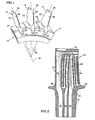
- FIG. 1 is a diagrammatic perspective view of the rotor assembly section.
- FIG. 2 is a diagrammatic view of a sectioned rotor blade.
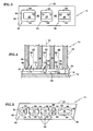
- FIG. 3 is a diagrammatic bottom view of a rotor blade root, illustrating an embodiment of the root conduits.
- FIG. 4 is a diagrammatic sectional view of a rotor blade mounted within a disk recess, illustrating an embodiment of the root conduits.
- FIG. 5 is a diagrammatic bottom view of a rotor blade root, illustrating an embodiment of the root conduits.
- Referring to FIG. 1, a
rotor blade assembly 10 for a gas turbine engine is provided having adisk 12 and a plurality ofrotor blades 14. Thedisk 12 includes a plurality ofrecesses 16 circumferentially disposed around thedisk 12 and arotational centerline 18 about which thedisk 12 may rotate. Eachblade 14 includes aroot 20, anairfoil 22, aplatform 24, and a radial centerline 25. Theroot 20 includes a geometry (e.g., a fir tree configuration) that mates with that of one of therecesses 16 within thedisk 12. - Referring to FIG. 2, the
airfoil 22 includes a base 28, atip 30, a leadingedge 32, atrailing edge 34, a pressure-side wall 36 (see FIG. 1), and a suction-side wall 38 (see FIG. 1), and acavity 40. FIG. 2 diagrammatically illustrates anairfoil 22 sectioned between the leadingedge 32 and thetrailing edge 34. The pressure-side wall 36 and the suction-side wall 38 extend between the base 28 and thetip 30 and meet at the leadingedge 32 and thetrailing edge 34. - The
root 20 has a leadingedge conduit 42, at least onemid-body conduit 44, and atrailing edge conduit 46. Theconduits root 20 and into thecavity 40. Eachconduit centerline - Referring to FIGS. 2 - 5, the leading
edge conduit 42 includes aninlet 48 having aforward side 50, anaft side 52, asuction side 54, and apressure side 56. The forward, suction, andpressure sides centerline 58 of the leadingedge conduit 42. In some embodiments, theforward side 50 diverges at a different angle than the suction andpressure sides forward side 50 diverges at a greater angle than the suction andpressure sides aft side 52 is substantially parallel to thecenterline 58 of the leading edge conduit 42 (FIG. 3). In other embodiments, theaft side 52 converges toward the leadingedge end 60 of the root 20 (FIG. 4). In FIG. 4, theaft side 52 is diagrammatically shown as substantially parallel to theforward side 50. - The leading
edge conduit 42 is in fluid communication with one or more leadingedge passages 62 disposed within thecavity 40, adjacent the leadingedge 32 of theairfoil 22. The leadingedge conduit 42 provides the primary path into the leading edge passage(s) 62 for cooling air, and therefore theairfoil leading edge 32 is primarily cooled by the cooling air that enters theairfoil 22 through the leadingedge conduit 42. - The mid-body conduit(s) 44 includes an
inlet 64 having asuction side 66, apressure side 68, anaft side 70, and aforward side 72. The suction andpressure sides centerline 74 of themid-body conduit 44. In some embodiments, the aft andforward sides centerline 74 of the mid-body conduit 44 (FIG. 3). In other embodiments, theforward side 72 diverges toward the leadingedge end 60 of the root 20 (FIG. 4). In FIG. 4, theforward side 72 of the mid -body conduit 44 is shown as substantially parallel to theaft side 52 of the leadingedge conduit 42. - The mid-body conduit(s) 44 is in fluid communication with one or more mid-body passages 76 disposed within the
cavity 40. Themid-body conduit 44 provides the primary path into the mid-body passages 76 for cooling air, and therefore theairfoil 22 mid-body region is primarily cooled by the cooling air that enters theairfoil 22 through the mid -body conduit 44. - The trailing
edge conduit 46 includes aninlet 78 having anaft side 80, aforward side 82, asuction side 84, and apressure side 86. The suction and pressure sides 84, 86 each diverge from thecenterline 88 of the trailingedge conduit 46. In some embodiments, the aft and forward sides 80, 82 are substantially parallel to thecenterline 88 of the trailing edge conduit 46 (e.g., FIGS. 3 and 4). In some embodiments (e.g., FIG.5), theaft side 80 diverges from thecenterline 88 of the trailingedge conduit 46 - The trailing
edge conduit 46 is in fluid communication with one ormore passages 90 disposed within thecavity 40, adjacent the trailingedge 34 of theairfoil 22. The trailingedge conduit 46 provides the primary path into thepassages 90 for cooling air. Consequently, the trailingedge 34 is primarily cooled by cooling air that enters theairfoil 22 through the trailingedge conduit 46. - Referring to FIG.4, in the operation of the invention the
rotor blade root 20 is received within arecess 16 disposed within thedisk 12. Coolingair 91 enters thegap 92 between theblade root 20 andbase 94 of therecess 16, traveling in a direction that is approximately perpendicular to the radial centerline 25 of theblade 14. The coolingairflow 91 first encounters the leadingedge end 60 of theroot 20, and subsequently theleading edge conduit 42. Theforward side 50 of theleading edge conduit 42 facilitates the transition of cooling airflow into theleading edge conduit 42, and thereby lowers the pressure drop associated with the turn in cooling airflow relative to that which would be associated, for example, with a 90° turn. The divergent suction and pressure sides 54, 56 open theinlet 48 to facilitate cooling airflow entry from the sides. - Cooling
air 93 that travels past theleading edge conduit 42 encounters the one or moremid-body conduits 44. The divergent suction and pressure sides 66, 68 open theinlet 64 to facilitate cooling airflow entry from the sides, and to decrease the pressure drop for cooling airflow turning into theinlet 46 from the sides. In the embodiment that includes amid-body conduit inlet 64 with a divergentforward side 72, theinlet 64forward side 72 facilitates the transition of cooling airflow into themid-body conduit 44 as described above. Both embodiments of theforward side 72 do not decrease the cross-sectional area of theroot portion 96 disposed between theleading edge conduit 42 and themid-body conduit 44. Consequently, the blade root load capability is not negatively affected, as would be the case if the leading edge andmid-body conduit inlets - Cooling
air 95 that travels past themid-body conduit 44 encounters the trailingedge conduit inlet 78. The divergent suction and pressure sides 84, 86 open the inlet to facilitate cooling airflow entry from the sides, and to decrease the pressure drop for cooling airflow turning into theinlet 78 from the sides. In the embodiment that includes a trailingedge conduit inlet 78 with a divergentforward side 82, the inlet forwardside 82 facilitates the transition of cooling airflow into the trailingedge conduit 46 as described above. Both embodiments of the trailing edge conduit forwardside 82 do not decrease the cross-sectional area of theroot portion 98 extending between themid-body conduit 44 and the trailingedge conduit 46. Consequently, the blade root load capability is not negatively affected, as would be the case if mid-body and trailing edge conduit inlets 64, 78 flared toward one another.
Claims (10)
- A rotor blade (14), comprising:a hollow airfoil (22) having a cavity (40), and one or more cooling apertures (32,76,90);a root (20) attached to the airfoil (22), the root (20) having a leading edge conduit (42), at least one mid-body conduit (44), and a trailing edge conduit (46), wherein the conduits are operable to permit airflow through the root and into the cavity, and each conduit has a centerline (58,74,88);wherein the leading edge conduit (42) includes an inlet (48) having a suction side (54) and a pressure side (56) that each diverge linearly from the centerline (58) of the leading edge conduit (42), a forward side (50), and an aft side (52) that is substantially parallel to the centerline (58) of the leading edge conduit (42);wherein each of the at least one mid-body conduits (44) includes an inlet (64) having a suction side (66) and a pressure side (68) that each diverge from the centerline (74) of the mid-body conduit (44), an aft side (70) and a forward side (72) that is substantially parallel to the centerline (74) of the mid-body conduit (44); andwherein the trailing edge conduit (46) includes an inlet (78) having a suction side (84) and a pressure side (86), that each diverge from the centerline (88) of the trailing edge conduit (46), and a forward side (82) and an aft side (80) that are substantially parallel to the centerline (88) of the trailing edge conduit (46); characterised in that said forward side (50) of said leading edge conduit inlet (48) diverges linearly from the centreline of the leading edge conduit (42) and in that said aft side (70) of said mid-body conduit inlet (64) is substantially parallel to the centreline (74) of said mid-body conduit (44).
- The rotor blade of claim 1, wherein the suction side (54) and pressure side (56) of the leading edge conduit inlet (48) diverge at a different angle than the forward side (50).
- A rotor blade (14), comprising:a hollow airfoil (22) having a cavity (40), and one or more cooling apertures (32,76,90);a root (20) attached to the airfoil (22), the root (20) having a leading edge conduit (42), at least one mid-body conduit (44), and a trailing edge conduit (46), wherein the conduits are operable to permit airflow through the root and into the cavity, and each conduit has a centerline (58,74,88);wherein the leading edge conduit (42) includes an inlet (48) having a suction side (54), and a pressure side (56) that each diverge linearly from the centerline (58) of the leading edge conduit (42), an aft side (52), and a forward side (50);wherein each of the at least one mid-body conduits (44) includes an inlet (64) having a suction side (66), and a pressure side (68) that diverge linearly from the centerline (74) of the mid-body conduit (44), a forward side (72) and an aft side (70); andwherein the trailing edge conduit (46) includes an inlet (78) having a suction side (84) and a pressure side (86), that each diverge from the centerline (88) of the trailing edge conduit (46), and a forward side (82) that is substantially parallel to the centerline (88) of the trailing edge conduit (46); characterised in that:said forward side (50) of said leading edge conduit inlet (48) diverges linearly from the centreline (58) of the leading edge conduit; and said forward side (72) of said mid-body conduit inlet (64) diverges linearly from the centreline(74) of the mid-body conduit (44); and said aft side (70) of said mid body conduit inlet (64) is substantially parallel to the centerline (74) of the mid-body conduit (44).
- The rotor blade of claim 3, wherein the suction side (54) and pressure side (56) of the leading edge conduit inlet (48) diverge at a different angle than the forward side (50) of the leading edge conduit inlet (42).
- A rotor blade (14), comprising:a hollow airfoil (22) having a cavity (40), and one or more cooling apertures (32,76,90);a root (20) attached to the airfoil (22), the root (20) having a leading edge conduit (42), at least one mid-body conduit (44), and a trailing edge conduit (46), wherein the conduits are operable to permit airflow through the root and into the cavity, and each conduit has a centerline;wherein the leading edge conduit (42) includes an inlet (48) having a suction side (54), and a pressure side (56) that each diverge linearly from the centerline (58) of the leading edge conduit (42), an aft side (52), and a forward side (50);wherein each of the at least one mid-body conduits (44) includes an inlet (64) having a suction side (66), a pressure side (68), and an aft side (70) that each diverge linearly from the centerline (74) of the mid-body conduit (44) and a forward side (72); andwherein the trailing edge conduit (46) includes an inlet (78) having a suction side (84), and a pressure side (86) that diverge linearly from the centerline (88) of the trailing edge conduit (46), an aft side (80) that is substantially parallel to the centerline (88) of the trailing edge conduit (46) and a forward side (82); characterised in that said forward side (50) of the leading edge conduit inlet (48) diverges linearly from the centreline (58) of the leading edge conduit (42) and said forward side (82) of said trailing edge conduit inlet diverges linearly from the centreline (88) of the trailing edge conduit (46).
- The rotor blade of claim 5, wherein the suction side (54,66) and pressure side (56,68) of the leading edge conduit inlet (48) and the mid-body inlet (64) diverge at a different angle than the forward sides (50,72) of the leading edge conduit inlet (48) and the mid-body inlet (64).
- The rotor blade of any of claims 3 to 6, wherein the forward side (72) of the at least one mid-body conduit inlet (64) is approximately parallel to the aft side (52) of the leading edge conduit inlet (48).
- The rotor blade of claim 7, wherein the forward side (82) of the trailing edge conduit inlet (78) is approximately parallel to the forward side (72) of the at least one mid-body conduit inlet (64).
- A rotor blade (14), comprising:a hollow airfoil (22) having a cavity (40), and one or more cooling apertures (32,76,90);a root (20) attached to the airfoil (22), the root (20) having a leading edge conduit (42), at least one mid-body conduit (44), and a trailing edge conduit (46), wherein the conduits are operable to permit airflow through the root and into the cavity, and each conduit has a centerline;wherein the leading edge conduit (42) includes an inlet (48) having a suction side (54), and a pressure side (56) that each diverge linearly from the centerline (58) of the leading edge conduit (42), an aft side (52), and a forward side (50);wherein each of the at least one mid-body conduits (44) includes an inlet (64) having a suction side (66), and a pressure side (68) that diverge linearly from the centerline (74) of the mid-body conduit (44), a forward side (72) and an aft side (70); andwherein the trailing edge conduit (46) includes an inlet (78) having a suction side (84), and a pressure side (86), that each diverge linearly from the centerline (88) of the trailing edge conduit (46), and a forward side (82) that is substantially parallel to the centerline (88) of the trailing edge conduit (46), and an aft side (80); characterised in that:said forward side (50) of the leading edge conduit inlet (48) diverges linearly from the centreline (58) of the leading edge conduit (42), in that said aft side (70) of said mid-body conduit (44) is substantially parallel to the centerline (74) of the mid-body conduit (44), and in that said aft side (78) of said trailing edge conduit inlet (78) diverges linearly from the centreline (88) of the trailing edge conduit (46).
- The rotor blade of claim 9, wherein the suction side (84) and pressure side (86) of the trailing edge conduit inlet (78) diverge at a different angle than the aft side (80) of the trailing edge conduit inlet (78).
Applications Claiming Priority (2)
| Application Number | Priority Date | Filing Date | Title |
|---|---|---|---|
| US855149 | 1997-05-13 | ||
| US10/855,149 US7059825B2 (en) | 2004-05-27 | 2004-05-27 | Cooled rotor blade |
Publications (2)
| Publication Number | Publication Date |
|---|---|
| EP1605137A1 EP1605137A1 (en) | 2005-12-14 |
| EP1605137B1 true EP1605137B1 (en) | 2007-04-04 |
Family
ID=34941472
Family Applications (1)
| Application Number | Title | Priority Date | Filing Date |
|---|---|---|---|
| EP05253260A Expired - Lifetime EP1605137B1 (en) | 2004-05-27 | 2005-05-27 | Cooled rotor blade |
Country Status (4)
| Country | Link |
|---|---|
| US (1) | US7059825B2 (en) |
| EP (1) | EP1605137B1 (en) |
| JP (1) | JP2005337251A (en) |
| DE (1) | DE602005000796T2 (en) |
Families Citing this family (18)
| Publication number | Priority date | Publication date | Assignee | Title |
|---|---|---|---|---|
| US7632071B2 (en) | 2005-12-15 | 2009-12-15 | United Technologies Corporation | Cooled turbine blade |
| US7625178B2 (en) * | 2006-08-30 | 2009-12-01 | Honeywell International Inc. | High effectiveness cooled turbine blade |
| US7819629B2 (en) * | 2007-02-15 | 2010-10-26 | Siemens Energy, Inc. | Blade for a gas turbine |
| US7871246B2 (en) * | 2007-02-15 | 2011-01-18 | Siemens Energy, Inc. | Airfoil for a gas turbine |
| EP1975372A1 (en) * | 2007-03-28 | 2008-10-01 | Siemens Aktiengesellschaft | Eccentric chamfer at inlet of branches in a flow channel |
| US7967563B1 (en) * | 2007-11-19 | 2011-06-28 | Florida Turbine Technologies, Inc. | Turbine blade with tip section cooling channel |
| EP2236746A1 (en) * | 2009-03-23 | 2010-10-06 | Alstom Technology Ltd | Gas turbine |
| US8353669B2 (en) * | 2009-08-18 | 2013-01-15 | United Technologies Corporation | Turbine vane platform leading edge cooling holes |
| US8622702B1 (en) * | 2010-04-21 | 2014-01-07 | Florida Turbine Technologies, Inc. | Turbine blade with cooling air inlet holes |
| US8920123B2 (en) | 2012-12-14 | 2014-12-30 | Siemens Aktiengesellschaft | Turbine blade with integrated serpentine and axial tip cooling circuits |
| US9850761B2 (en) | 2013-02-04 | 2017-12-26 | United Technologies Corporation | Bell mouth inlet for turbine blade |
| KR20150109281A (en) * | 2014-03-19 | 2015-10-01 | 알스톰 테크놀러지 리미티드 | Rotor shaft with cooling bore inlets |
| FR3021697B1 (en) * | 2014-05-28 | 2021-09-17 | Snecma | OPTIMIZED COOLING TURBINE BLADE |
| EP3059394B1 (en) * | 2015-02-18 | 2019-10-30 | Ansaldo Energia Switzerland AG | Turbine blade and set of turbine blades |
| US20170234447A1 (en) * | 2016-02-12 | 2017-08-17 | United Technologies Corporation | Methods and systems for modulating airflow |
| US10830052B2 (en) | 2016-09-15 | 2020-11-10 | Honeywell International Inc. | Gas turbine component with cooling aperture having shaped inlet and method of forming the same |
| WO2019008656A1 (en) * | 2017-07-04 | 2019-01-10 | 東芝エネルギーシステムズ株式会社 | Turbine blade and turbine |
| US11021961B2 (en) | 2018-12-05 | 2021-06-01 | General Electric Company | Rotor assembly thermal attenuation structure and system |
Family Cites Families (9)
| Publication number | Priority date | Publication date | Assignee | Title |
|---|---|---|---|---|
| GB2165315B (en) * | 1984-10-04 | 1987-12-31 | Rolls Royce | Improvements in or relating to hollow fluid cooled turbine blades |
| US5700131A (en) * | 1988-08-24 | 1997-12-23 | United Technologies Corporation | Cooled blades for a gas turbine engine |
| US5599166A (en) * | 1994-11-01 | 1997-02-04 | United Technologies Corporation | Core for fabrication of gas turbine engine airfoils |
| US5738489A (en) * | 1997-01-03 | 1998-04-14 | General Electric Company | Cooled turbine blade platform |
| US6139269A (en) * | 1997-12-17 | 2000-10-31 | United Technologies Corporation | Turbine blade with multi-pass cooling and cooling air addition |
| EP1041246A1 (en) * | 1999-03-29 | 2000-10-04 | Siemens Aktiengesellschaft | Casted gas turbine blade with inner cooling, method and device for manufacturing a manifold of the gas turbine blade |
| US6634858B2 (en) * | 2001-06-11 | 2003-10-21 | Alstom (Switzerland) Ltd | Gas turbine airfoil |
| US6932570B2 (en) * | 2002-05-23 | 2005-08-23 | General Electric Company | Methods and apparatus for extending gas turbine engine airfoils useful life |
| US7014424B2 (en) * | 2003-04-08 | 2006-03-21 | United Technologies Corporation | Turbine element |
-
2004
- 2004-05-27 US US10/855,149 patent/US7059825B2/en not_active Expired - Lifetime
-
2005
- 2005-05-25 JP JP2005152247A patent/JP2005337251A/en not_active Ceased
- 2005-05-27 DE DE602005000796T patent/DE602005000796T2/en not_active Expired - Lifetime
- 2005-05-27 EP EP05253260A patent/EP1605137B1/en not_active Expired - Lifetime
Also Published As
| Publication number | Publication date |
|---|---|
| US20050265841A1 (en) | 2005-12-01 |
| EP1605137A1 (en) | 2005-12-14 |
| DE602005000796T2 (en) | 2007-08-16 |
| US7059825B2 (en) | 2006-06-13 |
| DE602005000796D1 (en) | 2007-05-16 |
| JP2005337251A (en) | 2005-12-08 |
Similar Documents
| Publication | Publication Date | Title |
|---|---|---|
| EP1605137B1 (en) | Cooled rotor blade | |
| US10822957B2 (en) | Fillet optimization for turbine airfoil | |
| US20240159151A1 (en) | Airfoil for a turbine engine | |
| US10436038B2 (en) | Turbine engine with an airfoil having a tip shelf outlet | |
| US5503529A (en) | Turbine blade having angled ejection slot | |
| EP1939399B1 (en) | Axial flow turbine assembly | |
| JP5289694B2 (en) | Turbine airfoil curved squealer tip with tip shelf | |
| EP1816353B1 (en) | Bleed system for a compressor stage of a turbine engine and corresponding component for use in a turbine engine | |
| EP2374997B1 (en) | Component for a gas turbine engine | |
| US20140023497A1 (en) | Cooled turbine blade tip shroud with film/purge holes | |
| CA2567940C (en) | Methods and apparatuses for gas turbine engines | |
| EP2597263B1 (en) | Bucket assembly for turbine system | |
| EP2930371B1 (en) | Turbomachine with a bleeding port | |
| US10267161B2 (en) | Gas turbine engine with fillet film holes | |
| US11525360B2 (en) | Ventilated high pressure blade of a helicopter turbine comprising an upstream duct and a central cooling chamber | |
| US11933193B2 (en) | Turbine engine with an airfoil having a set of dimples | |
| US20170211393A1 (en) | Gas turbine aerofoil trailing edge | |
| US20180073370A1 (en) | Turbine blade cooling | |
| CN108979730A (en) | Airfoil and for cooling down the device and method at the top of the airfoil | |
| JP7341683B2 (en) | Tip shroud fillet for turbine rotor blades | |
| CN109891055B (en) | Airfoil for a turbine engine and corresponding method of cooling | |
| CN108691571B (en) | Engine component with flow enhancer | |
| EP3431710A1 (en) | Shield for a turbine engine airfoil | |
| WO2018004766A1 (en) | Airfoil and blade for a turbine engine, and corresponding method of flowing a cooling fluid |
Legal Events
| Date | Code | Title | Description |
|---|---|---|---|
| PUAI | Public reference made under article 153(3) epc to a published international application that has entered the european phase |
Free format text: ORIGINAL CODE: 0009012 |
|
| AK | Designated contracting states |
Kind code of ref document: A1 Designated state(s): AT BE BG CH CY CZ DE DK EE ES FI FR GB GR HU IE IS IT LI LT LU MC NL PL PT RO SE SI SK TR |
|
| AX | Request for extension of the european patent |
Extension state: AL BA HR LV MK YU |
|
| 17P | Request for examination filed |
Effective date: 20051104 |
|
| AKX | Designation fees paid |
Designated state(s): DE FR GB IT |
|
| GRAP | Despatch of communication of intention to grant a patent |
Free format text: ORIGINAL CODE: EPIDOSNIGR1 |
|
| GRAS | Grant fee paid |
Free format text: ORIGINAL CODE: EPIDOSNIGR3 |
|
| GRAA | (expected) grant |
Free format text: ORIGINAL CODE: 0009210 |
|
| AK | Designated contracting states |
Kind code of ref document: B1 Designated state(s): DE FR GB IT |
|
| REG | Reference to a national code |
Ref country code: GB Ref legal event code: FG4D |
|
| REF | Corresponds to: |
Ref document number: 602005000796 Country of ref document: DE Date of ref document: 20070516 Kind code of ref document: P |
|
| ET | Fr: translation filed | ||
| PLBE | No opposition filed within time limit |
Free format text: ORIGINAL CODE: 0009261 |
|
| STAA | Information on the status of an ep patent application or granted ep patent |
Free format text: STATUS: NO OPPOSITION FILED WITHIN TIME LIMIT |
|
| 26N | No opposition filed |
Effective date: 20080107 |
|
| PGFP | Annual fee paid to national office [announced via postgrant information from national office to epo] |
Ref country code: FR Payment date: 20070522 Year of fee payment: 3 |
|
| REG | Reference to a national code |
Ref country code: FR Ref legal event code: ST Effective date: 20090119 |
|
| PG25 | Lapsed in a contracting state [announced via postgrant information from national office to epo] |
Ref country code: FR Free format text: LAPSE BECAUSE OF NON-PAYMENT OF DUE FEES Effective date: 20080602 |
|
| PGFP | Annual fee paid to national office [announced via postgrant information from national office to epo] |
Ref country code: IT Payment date: 20080531 Year of fee payment: 4 |
|
| REG | Reference to a national code |
Ref country code: DE Ref legal event code: R082 Ref document number: 602005000796 Country of ref document: DE Representative=s name: SCHMITT-NILSON SCHRAUD WAIBEL WOHLFROM PATENTA, DE |
|
| REG | Reference to a national code |
Ref country code: DE Ref legal event code: R082 Ref document number: 602005000796 Country of ref document: DE Representative=s name: SCHMITT-NILSON SCHRAUD WAIBEL WOHLFROM PATENTA, DE Ref country code: DE Ref legal event code: R081 Ref document number: 602005000796 Country of ref document: DE Owner name: UNITED TECHNOLOGIES CORP. (N.D.GES.D. STAATES , US Free format text: FORMER OWNER: UNITED TECHNOLOGIES CORP., HARTFORD, CONN., US |
|
| PGFP | Annual fee paid to national office [announced via postgrant information from national office to epo] |
Ref country code: DE Payment date: 20190418 Year of fee payment: 15 |
|
| REG | Reference to a national code |
Ref country code: DE Ref legal event code: R119 Ref document number: 602005000796 Country of ref document: DE |
|
| PG25 | Lapsed in a contracting state [announced via postgrant information from national office to epo] |
Ref country code: DE Free format text: LAPSE BECAUSE OF NON-PAYMENT OF DUE FEES Effective date: 20201201 |
|
| PGFP | Annual fee paid to national office [announced via postgrant information from national office to epo] |
Ref country code: GB Payment date: 20240419 Year of fee payment: 20 |
|
| REG | Reference to a national code |
Ref country code: GB Ref legal event code: PE20 Expiry date: 20250526 |
|
| PG25 | Lapsed in a contracting state [announced via postgrant information from national office to epo] |
Ref country code: GB Free format text: LAPSE BECAUSE OF EXPIRATION OF PROTECTION Effective date: 20250526 |