EP2599669A1 - Pedestrian protection airbag - Google Patents
Pedestrian protection airbag Download PDFInfo
- Publication number
- EP2599669A1 EP2599669A1 EP20110191104 EP11191104A EP2599669A1 EP 2599669 A1 EP2599669 A1 EP 2599669A1 EP 20110191104 EP20110191104 EP 20110191104 EP 11191104 A EP11191104 A EP 11191104A EP 2599669 A1 EP2599669 A1 EP 2599669A1
- Authority
- EP
- European Patent Office
- Prior art keywords
- airbag
- tethering member
- pedestrian protection
- tethering
- vehicle
- Prior art date
- Legal status (The legal status is an assumption and is not a legal conclusion. Google has not performed a legal analysis and makes no representation as to the accuracy of the status listed.)
- Granted
Links
Images



Classifications
-
- B—PERFORMING OPERATIONS; TRANSPORTING
- B60—VEHICLES IN GENERAL
- B60R—VEHICLES, VEHICLE FITTINGS, OR VEHICLE PARTS, NOT OTHERWISE PROVIDED FOR
- B60R21/00—Arrangements or fittings on vehicles for protecting or preventing injuries to occupants or pedestrians in case of accidents or other traffic risks
- B60R21/34—Protecting non-occupants of a vehicle, e.g. pedestrians
- B60R21/36—Protecting non-occupants of a vehicle, e.g. pedestrians using airbags
-
- B—PERFORMING OPERATIONS; TRANSPORTING
- B60—VEHICLES IN GENERAL
- B60R—VEHICLES, VEHICLE FITTINGS, OR VEHICLE PARTS, NOT OTHERWISE PROVIDED FOR
- B60R21/00—Arrangements or fittings on vehicles for protecting or preventing injuries to occupants or pedestrians in case of accidents or other traffic risks
- B60R21/02—Occupant safety arrangements or fittings, e.g. crash pads
- B60R21/16—Inflatable occupant restraints or confinements designed to inflate upon impact or impending impact, e.g. air bags
- B60R21/23—Inflatable members
- B60R21/231—Inflatable members characterised by their shape, construction or spatial configuration
- B60R21/2334—Expansion control features
- B60R21/2338—Tethers
-
- B—PERFORMING OPERATIONS; TRANSPORTING
- B60—VEHICLES IN GENERAL
- B60R—VEHICLES, VEHICLE FITTINGS, OR VEHICLE PARTS, NOT OTHERWISE PROVIDED FOR
- B60R21/00—Arrangements or fittings on vehicles for protecting or preventing injuries to occupants or pedestrians in case of accidents or other traffic risks
- B60R21/02—Occupant safety arrangements or fittings, e.g. crash pads
- B60R21/16—Inflatable occupant restraints or confinements designed to inflate upon impact or impending impact, e.g. air bags
- B60R21/23—Inflatable members
- B60R21/231—Inflatable members characterised by their shape, construction or spatial configuration
- B60R21/2334—Expansion control features
- B60R21/2342—Tear seams
-
- B—PERFORMING OPERATIONS; TRANSPORTING
- B60—VEHICLES IN GENERAL
- B60R—VEHICLES, VEHICLE FITTINGS, OR VEHICLE PARTS, NOT OTHERWISE PROVIDED FOR
- B60R21/00—Arrangements or fittings on vehicles for protecting or preventing injuries to occupants or pedestrians in case of accidents or other traffic risks
- B60R21/02—Occupant safety arrangements or fittings, e.g. crash pads
- B60R21/16—Inflatable occupant restraints or confinements designed to inflate upon impact or impending impact, e.g. air bags
- B60R21/23—Inflatable members
- B60R21/231—Inflatable members characterised by their shape, construction or spatial configuration
- B60R21/2334—Expansion control features
- B60R21/2338—Tethers
- B60R2021/23382—Internal tether means
-
- B—PERFORMING OPERATIONS; TRANSPORTING
- B60—VEHICLES IN GENERAL
- B60R—VEHICLES, VEHICLE FITTINGS, OR VEHICLE PARTS, NOT OTHERWISE PROVIDED FOR
- B60R21/00—Arrangements or fittings on vehicles for protecting or preventing injuries to occupants or pedestrians in case of accidents or other traffic risks
- B60R21/02—Occupant safety arrangements or fittings, e.g. crash pads
- B60R21/16—Inflatable occupant restraints or confinements designed to inflate upon impact or impending impact, e.g. air bags
- B60R21/23—Inflatable members
- B60R21/231—Inflatable members characterised by their shape, construction or spatial configuration
- B60R21/2334—Expansion control features
- B60R21/2338—Tethers
- B60R2021/23386—External tether means
Definitions
- the present disclosure relates to a pedestrian protection airbag for a vehicle.
- the disclosure further relates to a vehicle comprising such a pedestrian protection airbag and a method of deployment of such a pedestrian protection airbag.
- a vehicle such as a car
- the pedestrian/cyclist may be thrown towards the windscreen and/or the A-pillars.
- an inflatable pedestrian protection airbag which deploys and at least partly covers the windscreen and/or the A-pillars, so that the pedestrian/cyclist instead hits the softer airbag.
- the airbag is stored in a housing under the bonnet of the vehicle.
- the airbag is deployed, i.e. inflated, in order to at least partly cover the windscreen and/or the A-pillars.
- Document US 2006/0151228 A1 discloses a pedestrian protection airbag system for protecting pedestrians and cyclists.
- the airbag is deployable to protect a pedestrian or a cyclist who impacts with the vehicle.
- the airbag which is deployed from a housing below the bonnet, includes a section or a chamber near the hinges of the bonnet. As a result, the airbag is deployable above the bonnet along the entire width of the vehicle in front of the lower area of the windscreen and the A-pillars.
- the lateral ends of the airbag extend over the A-pillars in such a way that they are upwardly oriented and are additionally fixed by a tethering member in the form of a strap after deployment.
- a number of embodiments disclose various arrangements of the tethering members, e.g. connecting an upper corner of the airbag to the bonnet or to the housing.
- the suggested airbag of US 2006/0151228 A1 has a rather complex shape, in particular due to the section or chamber near the hinges of the bonnet.
- the illustrated tethering members risk getting tangled during deployment.
- an impacting pedestrian/ cyclist can get tangled in the tethering member and be injured by the tethering member.
- the object of the present disclosure is to overcome or ameliorate at least one of the disadvantages of the prior art, or to provide a useful alternative.
- a pedestrian protection airbag for a vehicle.
- the airbag is adapted to be deployed along a windscreen and/ or A-pillars of the vehicle, is inflatable to a deployed state and has a projected periphery.
- the airbag comprises at least one tethering member connecting a first region of the airbag with a second region of the airbag along a path, the path being arranged within the projected periphery of the airbag when in the deployed state.
- the term projected periphery of the airbag relates to when the airbag, in its deployed state, is projected to a plane forming a main plane of the windscreen of the vehicle.
- the projected periphery is thus substantially a 2-dimensional feature.
- a peripheral seam of the airbag substantially coincides, at least partly, with the projected periphery.
- path relates to the airbag in the deployed state and describes the path along which the tethering member extends when the airbag is in its deployed state.
- the airbag is stored in a housing below a bonnet of the vehicle.
- the bonnet is in American English often called the hood.
- the path is herein used to define the active part of the tethering member, i.e. the part forming an effective length of the tethering member.
- both ends of the tethering member are attached to the airbag, such that the full length of the tethering member forms an effective length making up the path.
- the tethering member may not be attached at its end, but a distance away from the end, such that there is a loose end. In that case, the loose end will be inactive as regards stabilizing the deploying/ deployed airbag, and thus the loose end does not form part of the path.
- the at least one tethering member may extend inside the airbag or along the outer surface of the airbag.
- the path does not extend outside the projected periphery of the airbag.
- the tethering member of the proposed invention does not extend in the free air between two portions of the airbag, as disclosed in US 2006/0151228 A1 , wherein a strap is shown to extend between an upper corner of the airbag and an upper edge of the central region.
- a strap is attached at its ends to the airbag, but extends for essentially its whole length in the free air outside the projected periphery of the airbag, when the airbag is deployed.
- the strap of US 2006/0151228 A1 neither extends inside of the airbag, nor along the outer surface of the airbag.
- the tethering member does not extend to an attachment position outside of the airbag, such as a housing for the pedestrian protection airbag located below the bonnet of the vehicle, the bonnet itself, a location in an engine compartment or in a plenum area of the vehicle.
- the pedestrian protection airbag may form part of a pedestrian protection airbag system, which optionally may contain at least one external stabilization member, connecting the airbag to any of the above-mentioned positions outside of the airbag.
- external stabilization members are known by the skilled person and will not be discussed in any further detail herein. Further, such an external stabilization member extending at least partly outside of the projected periphery of the airbag should be distinguished from the tethering member forming part of this disclosure, which extends within the projected periphery of the airbag.
- the integration of the pedestrian protection airbag in the vehicle is made easier as compared to a conventional pedestrian protection airbag.
- the pedestrian protection airbag according to the disclosure is further easier to pack in a housing and easier to mount in a vehicle than a conventional pedestrian protection airbag, due to the localization of the tethering member.
- the tethering member of this disclosure may further be useful during deployment of the airbag in order to control the process of deployment.
- the tethering member will help to keep the airbag in the intended position, wherein it at least partly covers the windscreen and/or the A-pillars of the vehicle. If no tethering member was used, the airbag would risk being pushed out of position.
- the tethering member of the disclosure may be made shorter than tethering members of prior art, e.g. as in US 2006/0151228 A1 . They are therefore cheaper to produce and easier to handle during manufacturing and during mounting.
- the risk that the tethering member is tangled during deployment of the airbag, e.g. in a wiper arm, is reduced as compared to prior art tethering members. Further, the risk that an impacting pedestrian/ cyclist gets tangled in the tethering member and thereby is injured is also reduced.
- front, rear and lateral used herein refer to the vehicle seen from the position of a driver.
- terms regarding the airbag like upper corner, upper region, upper edge, lower region, lower edge, left-hand, right hand etc, as well as percentage measures of the airbag, refer to the airbag in its deployed state.
- the first region of the airbag may be an upper region, and the second region of the airbag may be a lower region.
- the upper region of the airbag is defined as the region of the deployed airbag situated above an imaginary line L in lateral direction going through the deployed airbag at half of its height h along the windscreen at a centre line.
- the lower region is defined as situated below the imaginary line L.
- the centre line divides the airbag in a right-hand and a left-hand half.
- the halves are commonly mirror-images of each other.
- any number of tethering members may be used, such as one, two, three, four or five. For symmetry reasons, it is generally preferred to use the same number of tethering members for the left-hand half and the right-hand half of the airbag, but the number may also differ between the halves.
- the attachment points may vary between the tethering members for one or both ends of the tethering members.
- Suitable materials for the tethering members are textile, plastics and/ or metal wire.
- the tethering member is preferably a belt or a strap. It may be of the same material as the airbag itself and may be made as an integral unit with the main part of the airbag.
- the pedestrian protection airbag may be sold and used as a spare part, or as part of a vehicle.
- the at least one tethering member has a first end and a second end and both ends are attached to the airbag. Thereby, the full length of the tethering member forms the path and loose ends are avoided.
- At least one end of the tethering member may be attached at or adjacent to the projected periphery of the airbag, e.g. at a lower or upper edge. Further, by attaching the tethering member at or adjacent to the projected periphery, it may get a maximal extension within the projected periphery of the airbag in that particular section of the airbag.
- the end may be attached in a peripheral seam of the airbag. Thereby the attachment may be done when making the peripheral seam.
- seam is herein used to include actual seeming, but also other joining technologies such as welding or gluing.
- the at least one tethering member may comprise a tear seam attaching the at least one tethering member to itself or to the airbag.
- the tear seam may be designed such that it tears at a desired selectable applied force.
- the tear seam may provide a means for controlling the active length of the tethering member, e.g. by forming a loop of the tethering member, such that when the tear seam is intact the tethering member has a certain length, and when the tear seam is torn, the tethering member will have another, more extended active length.
- the tear seam may be used to control the shape of the airbag during deployment, by successively inflating different portions of the airbag.
- the at least one tethering member is arranged inside of the airbag. It thus extends through the interior of the airbag.
- the tethering member may then contribute to form the shape of the airbag both during deployment and when deployed, giving the airbag a more stable shape.
- the tethering member may be pretensioned.
- the tethering member may take the shortest way between its attachment points.
- the tethering member When extending inside the airbag, the tethering member is protected from the environment. This reduces the risk that the tethering member is damaged during deployment or when packing the airbag into the housing. The reduced risk of damage makes it possible to make the tethering member simpler, lighter and cheaper than a conventional tethering member. The risk that the impacting pedestrian/cyclist will get tangled and possibly injured by the tethering member is avoided, when the tethering member only extends internally within the airbag.
- the at least one tethering member may be attached to the interior of the airbag at at least one additional location being different from the projected periphery of the airbag.
- the deployment process may be controlled by influencing the successive shape of the inflating airbag, e.g. at which moment during the deployment process the corner portions are to be inflated.
- the at least one tethering member may be attached to the interior of the airbag at the at least one additional location by means of at least one tear seam.
- the tethering member may in addition, or as an alternative, comprise a tear seam attaching the tethering member to itself. By controlling at which moment during deployment the tear seam is torn, the inflation process can be controlled.
- a tethering member may comprise one or more tear seams. There may be a plurality of tethering members comprising tear seams. The tear seams may be arranged to tear at different moments, thereby controlling the shape of the airbag during deployment. This may help to prevent the deploying airbag from interfering with the housing, wipers, bonnet, bonnet hinges etc.
- the tear seams may be arranged such that at first only a first portion of the airbag is inflated, resulting in a good expansion out of the housing. Thereafter, the tear seam tears, and the airbag extends to its final deployed shape.
- This arrangement may be used both for tear seams attaching the tethering member to itself, as well as for tear seams attaching the tethering member to the airbag, or a combination of such tear seams.
- the deployment process may also be performed in a plurality of steps inflating successive portions of the airbag.
- the at least one tethering member may be arranged along the outer surface of the airbag.
- Such a tethering member anyway extends within the projected periphery of the airbag. It may be used to control the shape of the airbag by influencing its curvature.
- Such a tethering member may be attached to the outer surface of the airbag at at least one additional location being different from the projected periphery of the airbag. It may be attached at one, two, three, four or more extra locations, e.g. by at least one distinct attachment means, such as a tab, a strap a loop or a Velcro-type attachment. Alternatively, or as a complement, the tethering member may be at least partly continuously attached along the outer surface of the airbag, e.g. by being glued.
- the at least one tethering member may be arranged from an upper corner of the airbag to a lower edge of the airbag or from an upper edge of a central region to a lower corner of the airbag.
- the central region is defined as the region covering the windscreen, while the upper corners are substantially located over or adjacent to the A pillars.
- the at least one tethering member may extend over less than half the width of the airbag, preferably less than 40% and most preferably less than 30%. Thereby the tethering member can be made relatively short as compared to known tethering members.
- a pedestrian protection airbag system comprising the above-mentioned pedestrian protection airbag and the housing adapted to store the airbag.
- the housing is further adapted to be located below a bonnet of the vehicle.
- the pedestrian protection airbag system may be sold and used as a spare part.
- a vehicle comprising the above-mentioned pedestrian protection airbag or pedestrian protection airbag system.
- the at least one tethering member may further be used for preventing sideways swaying of the deployed airbag.
- a method of deployment of a pedestrian protection airbag along the windscreen and/or A-pillars of a vehicle has a projected periphery, is inflatable to a deployed state and comprises at least one tethering member, connecting a first region of the airbag with a second region of the airbag along a path, the path being arranged within the projected periphery of the airbag, when in the deployed state, wherein the shape of the airbag is controlled during the deployment process by means of the at least one tethering member, which may be pretensioned.
- the tethering member may comprise at least one tear seam connecting the at least one tethering member to the airbag and/or to itself, the method comprises the following steps for controlling the shape of the airbag during the deployment process:
- the at least one tear seem is thus used to control the order in which different portions of the airbag are inflated.
- the inflation process can be controlled.
- the inflation of a first portion of the airbag results in a good expansion out of the housing. Thereafter the tear seam/s may tear, and the airbag may extend to its final deployed shape.
- the protective action of the lower region of the airbag may be reached in a quicker way as compared to a normal airbag deployment process, since the lower region reaches its working pressure in less time.
- This arrangement may be used both for tear seams being part of the tethering member, as well as for tear seams attaching the tethering member to the interior of the airbag, or a combination of such tear seams.
- the deployment process may also be performed in a plurality of steps inflating successive portions of the airbag.
- FIG 1 is a schematic overview of a vehicle 1 equipped with a pedestrian protection airbag system 3 comprising a pedestrian protection airbag 5 according to a first embodiment of the invention.
- the airbag 5 is stored in a housing 7 during normal conditions.
- a sensor system not illustrated
- the airbag 5 is deployed, i.e. inflated to a deployed state, as seen in the Figure 1 .
- the purpose of the deployed airbag is to prevent the pedestrian/ cyclist from directly hitting the windscreen 9 and/or the A-pillars 11 of the vehicle. Instead the pedestrian/ cyclist impacts with the much softer airbag.
- the same sensor system may also be used to initiate a deployment of the bonnet 13, i.e.
- the airbag may deploy through the rear bonnet opening 17, which results from raising the rear end of the bonnet 13.
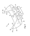
- FIG 2 a more detailed view of the pedestrian protection airbag system 3 according to the first embodiment of the invention is illustrated with the airbag 5 in its deployed state.
- the deployed airbag 5 is connected to the housing 7 by means of an inflating channel 19, through which the airbag 5 can be inflated.
- the deployed airbag 5 has a lateral extension w.
- a centre line 21 divides the airbag 5 in a right-hand and a left-hand half. The halves are commonly mirror-images of each other, as in Figure 2 .
- a lower region 23 is defined as the region of the deployed airbag 5 situated below an imaginary line L in lateral direction going through the deployed airbag 5 at half of its height h along the windscreen at the centre line 21.
- An upper region 25 is defined as the region of the deployed airbag 5 situated above the imaginary line L.
- the imaginary line L may coincide with the largest lateral extension w, as in Fig. 2 , but the largest lateral extension w may also be at another height.
- Figure 2 further illustrates that a tethering member 27, here in the form of a strap, extends from an upper right-hand corner 29 to a lower edge 31 at the projected periphery of the airbag 5.
- a first end 27a is attached to the airbag adjacent to the projected periphery of the airbag 5 at the upper right-hand corner 29.
- a second end 29b is attached adjacent to the projected periphery of the airbag 5 at the lower edge 31.
- another tethering member 33 extends from an upper left-hand corner 35 to the lower edge 31 of the airbag 5, having its ends 33a, 33b attached adjacent to the projected periphery of the airbag 5, e.g. attached in a peripheral seam.
- the tethering members 27, 33 extend over less than half of the width w of the airbag 5. As can be seen from Figure 2 , the tethering members 27, 33 are arranged inside of the airbag 5. Thereby there is no risk that the impacting pedestrian/cyclist would get tangled in the tethering members 27, 33.
- the tethering members 27, 33 will help to keep the airbag 5 in the intended position, wherein it at least partly covers the windscreen 9 and/or the A-pillars 11 of the vehicle. If no tethering members 27, 33 were used, the airbag 5 would risk being pushed out of position.
- the tethering members 27, 33 are further useful during deployment of the airbag 5 in order to control the process of the deployment, e.g. guiding the shape of the deploying airbag.
- external stabilization members 37 are attached between the lower edge 31 of the airbag 5 outside of the inflating channel 19 and the housing 7.
- the lower edge 31 of the airbag 5 may be connected to the bonnet, the plenum area or to a location in the engine compartment via the external stabilization members 37.
- Such external stabilization members 37 are known by the skilled person and will not be discussed in any further detail herein.
- FIG. 3 illustrates a second embodiment of the invention, in which tethering members 39, 41 instead are arranged along the outer surface of the airbag 5.
- the tethering members 39, 41 are attached to the outer surface of the airbag 5 by means of at least one distinct attachment means, such as a tab 43, strap or loop.
- the tethering members 39, 41 may be at least partly continuously attached along the outer surface of the airbag 5, e.g. by being glued.
- the ends 39a, 39b; 41 a, 41 b of the tethering members 39, 41 are attached adjacent to the projected periphery of the airbag, e.g. in the peripheral seam.
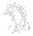
- Figure 4 illustrates a number of possible paths for tethering members:
- the central region is defined as the region covering the windscreen 9, while the upper corners 29, 33 are substantially located over or adjacent to the A pillars.
- tethering members may be used, such as one, two, three, four or five. For symmetry reasons, it is generally preferred to use the same number of tethering members for each half of the airbag, but the number may also differ.
- the tethering member may extend over less than half the lateral width w of the airbag, preferably less than 40% and most preferably less than 30%.
- tethering members are preferably attached at the projected periphery of the airbag, most preferably in the peripheral seam, but can be attached at any location of the airbag. Therefore, there are in principle an endless number of different paths of the tethering member available.
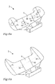
- the tethering member according to the invention may further be used in order to control the shape of the airbag 5 during a deployment process. Examples are illustrated by Figures 5a, 5b and 6a, 6b .
- a third embodiment of the invention is disclosed, wherein the tethering members 51, 53 extend inside of the airbag 5. They are, in addition to being attached at the ends, also attached at an additional location at the interior of the airbag 5 by a tear seam 55, 57, in this case adjacent to a lateral edge 59, 61 at the projected periphery of the airbag 5.
- the tear seams are designed to tear at a desired selectable applied force.
- a first portion 63 of the airbag is inflated, as illustrated in Figure 5a .
- the first portion 63 is restricted since the upper corners 29, 35 are restrained by the tethering members 51, 53, which during this phase still are attached to the interior of the airbag 5.
- the tear seams 55, 57 are torn and the airbag 5 expands further to its full deployed volume as in Figure 5b .
- the upper corners 29, 35 are then raised to respective positions, wherein they are located at least partly over or close to the A-pillars of the vehicle.
- Figures 5a and 5b disclose tethering members 51, 53 extending inside of the airbag 5, it would also be possible to use a tear seam for a tethering member extending along the outer surface of the airbag 5. The tear seam would then be located on the exterior of the airbag 5.
- FIGS 6a and 6b illustrate a fourth embodiment of the invention.
- Tethering members 65, 67, 71, 79 comprise a tear seam 73, 75, 77, 79 attaching each tethering member to itself at a location somewhere in between the ends.
- a first portion 81 of the airbag is inflated, as illustrated in Figure 6a .
- the first portion 81 is restricted by the tethering members 65, 67, 71, 79, which during this phase still are attached to themselves.
- the tear seams 65, 67, 71, 79 are torn and the airbag 5 expands further to its full deployed volume as in Figure 6b .
- the tethering members 65, 67, 71, 79 may extend inside of the airbag 5, as illustrated, or along the outer surface of the airbag 5. Even if Figures 6a and 6b illustrate four tethering members, any number, such as one, two, three or more may be used.
- the force at which the tear seam breaks may be selected individually for each tear seam, in order to control the deployment process of the airbag in greater detail.
Landscapes
- Engineering & Computer Science (AREA)
- Mechanical Engineering (AREA)
- Air Bags (AREA)
Abstract
Description
- The present disclosure relates to a pedestrian protection airbag for a vehicle. The disclosure further relates to a vehicle comprising such a pedestrian protection airbag and a method of deployment of such a pedestrian protection airbag.
- If a vehicle, such as a car, is involved in an accident, in which the front part of the vehicle hits a pedestrian or a cyclist, the pedestrian/cyclist may be thrown towards the windscreen and/or the A-pillars. In order to reduce the severity of these accidents, it is well-known to use an inflatable pedestrian protection airbag, which deploys and at least partly covers the windscreen and/or the A-pillars, so that the pedestrian/cyclist instead hits the softer airbag.
- During normal conditions, the airbag is stored in a housing under the bonnet of the vehicle. However, when a sensor system in the vehicle detects a potential collision risk with for example a pedestrian or cyclist, the airbag is deployed, i.e. inflated, in order to at least partly cover the windscreen and/or the A-pillars.
- Document
US 2006/0151228 A1 discloses a pedestrian protection airbag system for protecting pedestrians and cyclists. The airbag is deployable to protect a pedestrian or a cyclist who impacts with the vehicle. To prevent the lateral displacement of the segments of the deployed airbag in front of the A-pillars of the vehicle, the airbag, which is deployed from a housing below the bonnet, includes a section or a chamber near the hinges of the bonnet. As a result, the airbag is deployable above the bonnet along the entire width of the vehicle in front of the lower area of the windscreen and the A-pillars. The lateral ends of the airbag extend over the A-pillars in such a way that they are upwardly oriented and are additionally fixed by a tethering member in the form of a strap after deployment. A number of embodiments disclose various arrangements of the tethering members, e.g. connecting an upper corner of the airbag to the bonnet or to the housing. - However, the suggested airbag of
US 2006/0151228 A1 has a rather complex shape, in particular due to the section or chamber near the hinges of the bonnet. In addition, the illustrated tethering members risk getting tangled during deployment. There is also a risk that an impacting pedestrian/ cyclist can get tangled in the tethering member and be injured by the tethering member. - The object of the present disclosure is to overcome or ameliorate at least one of the disadvantages of the prior art, or to provide a useful alternative.
- It is desirable to provide a less complex pedestrian protection airbag as compared to pedestrian protection airbags used today, which airbag yet can reduce the risk for sideways displacement of the airbag. It is especially desirable that the airbag should stay in place, even if the pedestrian/ cyclist impacts from an oblique angle with respect to the windscreen of the vehicle.
- It is further desirable to reduce the risk that an impacting pedestrian/ cyclist can get tangled and possibly injured by a tethering member used to maintain the deployed airbag in place.
- The object above may be achieved by the invention according to claim 1.
- In a first aspect of the present invention, there is provided a pedestrian protection airbag for a vehicle. The airbag is adapted to be deployed along a windscreen and/ or A-pillars of the vehicle, is inflatable to a deployed state and has a projected periphery. The airbag comprises at least one tethering member connecting a first region of the airbag with a second region of the airbag along a path, the path being arranged within the projected periphery of the airbag when in the deployed state.
- The term projected periphery of the airbag relates to when the airbag, in its deployed state, is projected to a plane forming a main plane of the windscreen of the vehicle. The projected periphery is thus substantially a 2-dimensional feature. For many pedestrian protection airbags, a peripheral seam of the airbag substantially coincides, at least partly, with the projected periphery.
- The term path, as used in this disclosure, relates to the airbag in the deployed state and describes the path along which the tethering member extends when the airbag is in its deployed state. During normal conditions, the airbag is stored in a housing below a bonnet of the vehicle. The bonnet is in American English often called the hood.
- The path is herein used to define the active part of the tethering member, i.e. the part forming an effective length of the tethering member. Preferably both ends of the tethering member are attached to the airbag, such that the full length of the tethering member forms an effective length making up the path. However, in some cases the tethering member may not be attached at its end, but a distance away from the end, such that there is a loose end. In that case, the loose end will be inactive as regards stabilizing the deploying/ deployed airbag, and thus the loose end does not form part of the path.
- As further described below, the at least one tethering member may extend inside the airbag or along the outer surface of the airbag. In any case, according to the disclosure, the path does not extend outside the projected periphery of the airbag. Hence, the tethering member of the proposed invention, does not extend in the free air between two portions of the airbag, as disclosed in
US 2006/0151228 A1 , wherein a strap is shown to extend between an upper corner of the airbag and an upper edge of the central region. Such a strap is attached at its ends to the airbag, but extends for essentially its whole length in the free air outside the projected periphery of the airbag, when the airbag is deployed. The strap ofUS 2006/0151228 A1 neither extends inside of the airbag, nor along the outer surface of the airbag. - Moreover, since the path is arranged within the projected periphery of the airbag, the tethering member does not extend to an attachment position outside of the airbag, such as a housing for the pedestrian protection airbag located below the bonnet of the vehicle, the bonnet itself, a location in an engine compartment or in a plenum area of the vehicle.
- The pedestrian protection airbag may form part of a pedestrian protection airbag system, which optionally may contain at least one external stabilization member, connecting the airbag to any of the above-mentioned positions outside of the airbag. Such external stabilization members are known by the skilled person and will not be discussed in any further detail herein. Further, such an external stabilization member extending at least partly outside of the projected periphery of the airbag should be distinguished from the tethering member forming part of this disclosure, which extends within the projected periphery of the airbag.
- When the path of the tethering member is located within the projected periphery the airbag, as in the pedestrian protection airbag of this disclosure, the integration of the pedestrian protection airbag in the vehicle is made easier as compared to a conventional pedestrian protection airbag. The pedestrian protection airbag according to the disclosure is further easier to pack in a housing and easier to mount in a vehicle than a conventional pedestrian protection airbag, due to the localization of the tethering member. The tethering member of this disclosure may further be useful during deployment of the airbag in order to control the process of deployment.
- In case the pedestrian/cyclist impacts with the airbag, and especially if he/she hits at an oblique angle relative to the windscreen, the tethering member will help to keep the airbag in the intended position, wherein it at least partly covers the windscreen and/or the A-pillars of the vehicle. If no tethering member was used, the airbag would risk being pushed out of position.
- The tethering member of the disclosure may be made shorter than tethering members of prior art, e.g. as in
US 2006/0151228 A1 . They are therefore cheaper to produce and easier to handle during manufacturing and during mounting. - By using the tethering member according to the disclosure, the risk that the tethering member is tangled during deployment of the airbag, e.g. in a wiper arm, is reduced as compared to prior art tethering members. Further, the risk that an impacting pedestrian/ cyclist gets tangled in the tethering member and thereby is injured is also reduced.
- Due to the reduced risk of damage to the tethering member as compared to a conventional tethering member, a simpler construction, weaker material and/or less material may be used, resulting in less weight and/or reduced cost.
- The terms front, rear and lateral used herein refer to the vehicle seen from the position of a driver. Further, terms regarding the airbag, like upper corner, upper region, upper edge, lower region, lower edge, left-hand, right hand etc, as well as percentage measures of the airbag, refer to the airbag in its deployed state.
- The first region of the airbag may be an upper region, and the second region of the airbag may be a lower region. The upper region of the airbag is defined as the region of the deployed airbag situated above an imaginary line L in lateral direction going through the deployed airbag at half of its height h along the windscreen at a centre line. The lower region is defined as situated below the imaginary line L. The centre line divides the airbag in a right-hand and a left-hand half. The halves are commonly mirror-images of each other.
- Any number of tethering members may be used, such as one, two, three, four or five. For symmetry reasons, it is generally preferred to use the same number of tethering members for the left-hand half and the right-hand half of the airbag, but the number may also differ between the halves. When using two or more tethering members at one half of the airbag, the attachment points may vary between the tethering members for one or both ends of the tethering members.
- Suitable materials for the tethering members are textile, plastics and/ or metal wire. The tethering member is preferably a belt or a strap. It may be of the same material as the airbag itself and may be made as an integral unit with the main part of the airbag.
- The pedestrian protection airbag may be sold and used as a spare part, or as part of a vehicle.
- In an embodiment, the at least one tethering member has a first end and a second end and both ends are attached to the airbag. Thereby, the full length of the tethering member forms the path and loose ends are avoided.
- At least one end of the tethering member may be attached at or adjacent to the projected periphery of the airbag, e.g. at a lower or upper edge. Further, by attaching the tethering member at or adjacent to the projected periphery, it may get a maximal extension within the projected periphery of the airbag in that particular section of the airbag. The end may be attached in a peripheral seam of the airbag. Thereby the attachment may be done when making the peripheral seam. The term seam is herein used to include actual seeming, but also other joining technologies such as welding or gluing.
- The at least one tethering member may comprise a tear seam attaching the at least one tethering member to itself or to the airbag. The tear seam may be designed such that it tears at a desired selectable applied force. The tear seam may provide a means for controlling the active length of the tethering member, e.g. by forming a loop of the tethering member, such that when the tear seam is intact the tethering member has a certain length, and when the tear seam is torn, the tethering member will have another, more extended active length. In addition, the tear seam may be used to control the shape of the airbag during deployment, by successively inflating different portions of the airbag.
- In an embodiment the at least one tethering member is arranged inside of the airbag. It thus extends through the interior of the airbag. The tethering member may then contribute to form the shape of the airbag both during deployment and when deployed, giving the airbag a more stable shape. For this purpose, the tethering member may be pretensioned. By extending internally within the airbag, the tethering member may take the shortest way between its attachment points. As a comparison, a tethering member extending externally follows the curved outer surface of the deployed airbag.
- When extending inside the airbag, the tethering member is protected from the environment. This reduces the risk that the tethering member is damaged during deployment or when packing the airbag into the housing. The reduced risk of damage makes it possible to make the tethering member simpler, lighter and cheaper than a conventional tethering member. The risk that the impacting pedestrian/cyclist will get tangled and possibly injured by the tethering member is avoided, when the tethering member only extends internally within the airbag.
- The at least one tethering member may be attached to the interior of the airbag at at least one additional location being different from the projected periphery of the airbag. Thereby the deployment process may be controlled by influencing the successive shape of the inflating airbag, e.g. at which moment during the deployment process the corner portions are to be inflated.
- The at least one tethering member may be attached to the interior of the airbag at the at least one additional location by means of at least one tear seam. The tethering member may in addition, or as an alternative, comprise a tear seam attaching the tethering member to itself. By controlling at which moment during deployment the tear seam is torn, the inflation process can be controlled. A tethering member may comprise one or more tear seams. There may be a plurality of tethering members comprising tear seams. The tear seams may be arranged to tear at different moments, thereby controlling the shape of the airbag during deployment. This may help to prevent the deploying airbag from interfering with the housing, wipers, bonnet, bonnet hinges etc.
- The tear seams may be arranged such that at first only a first portion of the airbag is inflated, resulting in a good expansion out of the housing. Thereafter, the tear seam tears, and the airbag extends to its final deployed shape. By using this kind of arrangement, it is possible for the protective action of the lower region of the airbag to be reached in a quicker way as compared to a normal airbag deployment process, since the lower region reaches its working pressure in less time. This arrangement may be used both for tear seams attaching the tethering member to itself, as well as for tear seams attaching the tethering member to the airbag, or a combination of such tear seams. The deployment process may also be performed in a plurality of steps inflating successive portions of the airbag.
- As an alternative to the internal tethering member being arranged inside of the airbag, or as a complement, the at least one tethering member may be arranged along the outer surface of the airbag. Such a tethering member anyway extends within the projected periphery of the airbag. It may be used to control the shape of the airbag by influencing its curvature.
- Such a tethering member may be attached to the outer surface of the airbag at at least one additional location being different from the projected periphery of the airbag. It may be attached at one, two, three, four or more extra locations, e.g. by at least one distinct attachment means, such as a tab, a strap a loop or a Velcro-type attachment. Alternatively, or as a complement, the tethering member may be at least partly continuously attached along the outer surface of the airbag, e.g. by being glued.
- The at least one tethering member may be arranged from an upper corner of the airbag to a lower edge of the airbag or from an upper edge of a central region to a lower corner of the airbag. The central region is defined as the region covering the windscreen, while the upper corners are substantially located over or adjacent to the A pillars.
- The at least one tethering member may extend over less than half the width of the airbag, preferably less than 40% and most preferably less than 30%. Thereby the tethering member can be made relatively short as compared to known tethering members.
- In a second aspect of the present invention there is provided a pedestrian protection airbag system comprising the above-mentioned pedestrian protection airbag and the housing adapted to store the airbag. The housing is further adapted to be located below a bonnet of the vehicle. The pedestrian protection airbag system may be sold and used as a spare part.
- In a third aspect of the present invention there is provided a vehicle comprising the above-mentioned pedestrian protection airbag or pedestrian protection airbag system.
- In a fourth aspect of the present invention there is provided a use of at least one tethering member as described above for stabilization of a deploying/ deployed pedestrian protection airbag. The at least one tethering member may further be used for preventing sideways swaying of the deployed airbag.
- In a fifth aspect of the present invention there is provided a method of deployment of a pedestrian protection airbag along the windscreen and/or A-pillars of a vehicle. The airbag has a projected periphery, is inflatable to a deployed state and comprises at least one tethering member, connecting a first region of the airbag with a second region of the airbag along a path, the path being arranged within the projected periphery of the airbag, when in the deployed state, wherein the shape of the airbag is controlled during the deployment process by means of the at least one tethering member, which may be pretensioned.
- In addition, the tethering member may comprise at least one tear seam connecting the at least one tethering member to the airbag and/or to itself, the method comprises the following steps for controlling the shape of the airbag during the deployment process:
- a) inflating a first portion of the airbag, the first portion being restricted by the at least one tethering member,
- b) tearing the at least one tear seam,
- c) inflating a following portion of the airbag.
- The at least one tear seem is thus used to control the order in which different portions of the airbag are inflated. By controlling at which moment during deployment the tear seam is torn, the inflation process can be controlled.
- The inflation of a first portion of the airbag results in a good expansion out of the housing. Thereafter the tear seam/s may tear, and the airbag may extend to its final deployed shape. By using this kind of arrangement, the protective action of the lower region of the airbag may be reached in a quicker way as compared to a normal airbag deployment process, since the lower region reaches its working pressure in less time. This arrangement may be used both for tear seams being part of the tethering member, as well as for tear seams attaching the tethering member to the interior of the airbag, or a combination of such tear seams. The deployment process may also be performed in a plurality of steps inflating successive portions of the airbag.
- The present invention will hereinafter be further explained by means of non-limiting examples with reference to the appended figures wherein:
- Fig. 1
- is a schematic overview of a vehicle equipped with a pedestrian protection airbag according to a first embodiment of the invention after deployment of the airbag;
- Fig. 2
- illustrates the pedestrian protection airbag of
Figure 1 ; - Fig. 3
- illustrates a pedestrian protection airbag according to a second embodiment;
- Fig. 4
- illustrates some possible positions for a path of a tethering member;
- Fig. 5a, b
- illustrate a pedestrian protection airbag according to a third embodiment; and
- Fig. 6a, b
- illustrates a pedestrian protection airbag according to a fourth embodiment.
- It should be noted that the appended drawings are not necessarily drawn to scale and that the dimensions of some features of the present invention may have been exaggerated for the sake of clarity.
- The invention will, in the following, be exemplified by embodiments. It should however be realized that the embodiments are included in order to explain principles of the invention and not to limit the scope of the invention, defined by the appended claims. Details from two or more of the embodiments may be combined with each other.
-
Figure 1 is a schematic overview of a vehicle 1 equipped with a pedestrianprotection airbag system 3 comprising apedestrian protection airbag 5 according to a first embodiment of the invention. Theairbag 5 is stored in ahousing 7 during normal conditions. However, when a sensor system (not illustrated) in the vehicle detects a potential collision risk with for example a pedestrian or cyclist, theairbag 5 is deployed, i.e. inflated to a deployed state, as seen in theFigure 1 . The purpose of the deployed airbag is to prevent the pedestrian/ cyclist from directly hitting thewindscreen 9 and/or the A-pillars 11 of the vehicle. Instead the pedestrian/ cyclist impacts with the much softer airbag. Moreover, the same sensor system may also be used to initiate a deployment of thebonnet 13, i.e. rising the rear end of thebonnet 13. Thereby a clearance is provided between thebonnet 13 and theengine compartment 15, which also helps to minimize the impact forces on the pedestrian/ cyclist. The airbag may deploy through therear bonnet opening 17, which results from raising the rear end of thebonnet 13. - In
Figure 2 , a more detailed view of the pedestrianprotection airbag system 3 according to the first embodiment of the invention is illustrated with theairbag 5 in its deployed state. The deployedairbag 5 is connected to thehousing 7 by means of an inflatingchannel 19, through which theairbag 5 can be inflated. The deployedairbag 5 has a lateral extension w. Acentre line 21 divides theairbag 5 in a right-hand and a left-hand half. The halves are commonly mirror-images of each other, as inFigure 2 . Alower region 23 is defined as the region of the deployedairbag 5 situated below an imaginary line L in lateral direction going through the deployedairbag 5 at half of its height h along the windscreen at thecentre line 21. Anupper region 25 is defined as the region of the deployedairbag 5 situated above the imaginary line L. The imaginary line L may coincide with the largest lateral extension w, as inFig. 2 , but the largest lateral extension w may also be at another height. -
Figure 2 further illustrates that a tetheringmember 27, here in the form of a strap, extends from an upper right-hand corner 29 to alower edge 31 at the projected periphery of theairbag 5. Afirst end 27a is attached to the airbag adjacent to the projected periphery of theairbag 5 at the upper right-hand corner 29. A second end 29b is attached adjacent to the projected periphery of theairbag 5 at thelower edge 31. In the same way, another tetheringmember 33 extends from an upper left-hand corner 35 to thelower edge 31 of theairbag 5, having itsends airbag 5, e.g. attached in a peripheral seam. Thetethering members airbag 5. As can be seen fromFigure 2 , thetethering members airbag 5. Thereby there is no risk that the impacting pedestrian/cyclist would get tangled in thetethering members - In case the pedestrian/cyclist impacts with the
airbag 5, and especially if the/she hits at an oblique angle relative to the windscreen of the vehicle, thetethering members airbag 5 in the intended position, wherein it at least partly covers thewindscreen 9 and/or the A-pillars 11 of the vehicle. If notethering members airbag 5 would risk being pushed out of position. Thetethering members airbag 5 in order to control the process of the deployment, e.g. guiding the shape of the deploying airbag. - In the illustrated embodiment,
external stabilization members 37, not being part of the invention, are attached between thelower edge 31 of theairbag 5 outside of the inflatingchannel 19 and thehousing 7. Alternatively, thelower edge 31 of theairbag 5 may be connected to the bonnet, the plenum area or to a location in the engine compartment via theexternal stabilization members 37. Suchexternal stabilization members 37 are known by the skilled person and will not be discussed in any further detail herein. -
Figure 3 illustrates a second embodiment of the invention, in whichtethering members airbag 5. In the illustrated embodiment, thetethering members airbag 5 by means of at least one distinct attachment means, such as atab 43, strap or loop. As an alternative or a complement, thetethering members airbag 5, e.g. by being glued. In addition to these attachments along the outer surface, theends 39a, 39b; 41 a, 41 b of thetethering members -
Figure 4 illustrates a number of possible paths for tethering members: - A: connecting an
upper corner lower corner - B: connecting an
upper corner channel 19, as inFigures 2 and3 ; - C: connecting a
lower corner upper edge 47 of thecentral region 49. - The central region is defined as the region covering the
windscreen 9, while theupper corners - One or more of these paths may be used. Any number of tethering members may be used, such as one, two, three, four or five. For symmetry reasons, it is generally preferred to use the same number of tethering members for each half of the airbag, but the number may also differ. The tethering member may extend over less than half the lateral width w of the airbag, preferably less than 40% and most preferably less than 30%.
- The ends of tethering members are preferably attached at the projected periphery of the airbag, most preferably in the peripheral seam, but can be attached at any location of the airbag. Therefore, there are in principle an endless number of different paths of the tethering member available.
- The tethering member according to the invention may further be used in order to control the shape of the
airbag 5 during a deployment process. Examples are illustrated byFigures 5a, 5b and6a, 6b . - In
Figures 5a and 5b a third embodiment of the invention is disclosed, wherein thetethering members airbag 5. They are, in addition to being attached at the ends, also attached at an additional location at the interior of theairbag 5 by atear seam lateral edge airbag 5. The tear seams are designed to tear at a desired selectable applied force. In a first phase during the deployment process, afirst portion 63 of the airbag is inflated, as illustrated inFigure 5a . Thefirst portion 63 is restricted since theupper corners tethering members airbag 5. At a desired selectable force, being applied to thetethering members airbag 5 expands further to its full deployed volume as inFigure 5b . Theupper corners - Even if
Figures 5a and 5b disclosetethering members airbag 5, it would also be possible to use a tear seam for a tethering member extending along the outer surface of theairbag 5. The tear seam would then be located on the exterior of theairbag 5. -
Figures 6a and 6b illustrate a fourth embodiment of the invention.Tethering members tear seam first portion 81 of the airbag is inflated, as illustrated inFigure 6a . Thefirst portion 81 is restricted by thetethering members tethering members airbag 5 expands further to its full deployed volume as inFigure 6b . Thetethering members airbag 5, as illustrated, or along the outer surface of theairbag 5. Even ifFigures 6a and 6b illustrate four tethering members, any number, such as one, two, three or more may be used. Moreover, the force at which the tear seam breaks may be selected individually for each tear seam, in order to control the deployment process of the airbag in greater detail. - Further modifications of the embodiments described in the disclosure within the scope of the appended claims are feasible. As such, the present disclosure should not be considered as limited by the embodiments and figures described herein. Rather, the full scope of the disclosure should be determined by the appended claims, with reference to the description and drawings.
Claims (15)
- A pedestrian protection airbag (5) for a vehicle (1),
said airbag (5) being adapted to be deployed along a windscreen (9) and/or A-pillars (11) of said vehicle (1) and being inflatable to a deployed state, said airbag (5) having a projected periphery,
characterized in that
said airbag (5) comprises at least one tethering member (27, 33; 39, 41; 51, 53; 65, 67, 69, 71) connecting a first region (25) of said airbag (5) with a second region (23) of said airbag (5) along a path, said path being arranged within said projected periphery of said airbag (5), when said airbag (5) is in said deployed state. - The pedestrian protection airbag (5) according to claim 1, said tethering member (27, 33; 39, 41; 51, 53; 65, 67, 69, 71) having a first (27a; 33a; 39a; 41 a) end and a second end (27b; 33b; 39b; 41 b), wherein both said first and said second ends are attached to said airbag (5).
- The pedestrian protection airbag (5) according to claim 2, wherein at least one end (27a, 27b; 33a, 33b) of said first and second ends of said tethering member is attached at or adjacent to said projected periphery of said airbag (5), preferably in a peripheral seam.
- The pedestrian protection airbag (5) according to any one of the preceding claims, wherein said at least one tethering member (51, 53; 65, 67, 69, 71) comprises a tear seam (55, 57; 73, 75, 77, 79) attaching said at least one tethering member to itself or to said airbag (5).
- The pedestrian protection airbag (5) according to any one of the preceding claims, wherein said at least one tethering member (27, 33; 51, 53; 65, 67, 69, 71) is arranged inside of said airbag (5).
- The pedestrian protection airbag (5) according to claim 5, wherein said at least one tethering member (51, 53) is attached to an interior of said airbag (5) at at least one additional location being different from said projected periphery of said airbag (5).
- The pedestrian protection airbag (5) according to claim 6, wherein said at least one tethering member (51, 53) is attached to the interior of said airbag (5) at said at least one additional location by means of a tear seam (55, 57).
- The pedestrian protection airbag (5) according to any one claims 1-4, wherein said at least one tethering member (39, 41) is arranged along the outer surface of said airbag (5).
- The pedestrian protection airbag (5) according to claim 8, wherein said at least one tethering member (39, 41) is attached to the outer surface of said airbag (5) at at least one additional location being different from said projected periphery of said airbag (5).
- The pedestrian protection airbag (5) according to claim 9, wherein said at least one tethering member (39, 41) is attached to said outer surface at said at least one additional location by at least one distinct attachment means, such as a tab (43), a strap, a loop or a Velcro-type attachment or said tethering member (39, 41) is at least partly continuously attached along the outer surface of the airbag (5), e.g. by being glued.
- The pedestrian protection airbag (5) according to any one of the preceding claims, wherein said at least one tethering member (27, 33; 39, 41; 51, 53; 67, 71) is arranged from an upper corner (29, 35) of said airbag (5) to a lower edge (31) of said airbag (5).
- The pedestrian protection airbag (5) according to any one claims 1-10, wherein said at least one tethering member is arranged from an upper edge (47) of a central region (49) to a lower corner (43, 45) of said airbag (5).
- A vehicle comprising a pedestrian protection airbag (5) according to any one of claims 1-12.
- A method of deployment of a pedestrian protection airbag (5) along the windscreen (9) and/or A-pillars (11) of a vehicle (1), said airbag (5) being inflatable to a deployed, having a projected periphery and comprising at least one tethering member (27, 33; 39, 41; 51, 53; 65, 67, 69, 71) connecting a first region (25) of said airbag (5) with a second region (23) of said airbag (5) along a path, said path being arranged within said projected periphery of said airbag (5), when in said deployed state, wherein the shape of said airbag (5) is controlled during the deployment process by means of said at least one tethering member (27, 33; 39, 41; 51, 53; 65, 67, 69, 71).
- The method of claim 14, wherein said at least one tethering member (51, 53; 65, 67, 69, 71) comprises at least one tear seam (55, 57; 73, 75, 77, 79) connecting said at least one tethering member to said airbag (5) and/or to itself, said method comprises the following steps for controlling said shape of said airbag during the deployment process:a) inflating a first portion (63, 81) of said airbag (5), said first portion being restricted by said at least one tethering member (51, 53; 65, 67, 69, 71),b) tearing said at least one tear seam (55, 57),c) inflating a following portion of said airbag (5).
Priority Applications (3)
| Application Number | Priority Date | Filing Date | Title |
|---|---|---|---|
| EP11191104.6A EP2599669B1 (en) | 2011-11-29 | 2011-11-29 | Pedestrian protection airbag |
| US13/686,500 US8955634B2 (en) | 2011-11-29 | 2012-11-27 | Pedestrian protection airbag |
| CN201210495232.XA CN103129509B (en) | 2011-11-29 | 2012-11-28 | Pedestrian airbag |
Applications Claiming Priority (1)
| Application Number | Priority Date | Filing Date | Title |
|---|---|---|---|
| EP11191104.6A EP2599669B1 (en) | 2011-11-29 | 2011-11-29 | Pedestrian protection airbag |
Publications (2)
| Publication Number | Publication Date |
|---|---|
| EP2599669A1 true EP2599669A1 (en) | 2013-06-05 |
| EP2599669B1 EP2599669B1 (en) | 2015-07-22 |
Family
ID=45044414
Family Applications (1)
| Application Number | Title | Priority Date | Filing Date |
|---|---|---|---|
| EP11191104.6A Active EP2599669B1 (en) | 2011-11-29 | 2011-11-29 | Pedestrian protection airbag |
Country Status (3)
| Country | Link |
|---|---|
| US (1) | US8955634B2 (en) |
| EP (1) | EP2599669B1 (en) |
| CN (1) | CN103129509B (en) |
Cited By (3)
| Publication number | Priority date | Publication date | Assignee | Title |
|---|---|---|---|---|
| GB2520686A (en) * | 2013-11-27 | 2015-06-03 | Autoliv Dev | A pedestrian airbag |
| GB2557431A (en) * | 2016-10-21 | 2018-06-20 | Ford Global Tech Llc | Airbag assembly including internal and external tethers |
| WO2018203020A1 (en) | 2017-05-05 | 2018-11-08 | Paul Philippe Cord | Protection system for persons and goods comprising an inflatable structure with long duration of action |
Families Citing this family (25)
| Publication number | Priority date | Publication date | Assignee | Title |
|---|---|---|---|---|
| EP2481647B1 (en) * | 2011-01-26 | 2013-10-02 | Autoliv Development AB | Pedestrian airbag arrangement |
| JP5761260B2 (en) * | 2013-06-25 | 2015-08-12 | トヨタ自動車株式会社 | Vehicle collision damage reduction system |
| CN104417483B (en) * | 2013-08-30 | 2018-08-14 | 比亚迪股份有限公司 | A kind of automobile-used pedestrian protecting air bag and device |
| US9399441B2 (en) * | 2014-03-25 | 2016-07-26 | Ford Global Technologies, Llc | Shape adaptive passenger airbag |
| KR20150124003A (en) * | 2014-04-25 | 2015-11-05 | 현대자동차주식회사 | Pedestrian airbag system for vehicle |
| KR101664017B1 (en) * | 2014-07-25 | 2016-10-10 | 현대모비스 주식회사 | Air bag cushion device for protecting pedestrian |
| KR101640247B1 (en) * | 2014-08-29 | 2016-07-15 | 현대모비스 주식회사 | Air bag cushion device for protecting pedestrian |
| JP6327108B2 (en) * | 2014-10-21 | 2018-05-23 | トヨタ自動車株式会社 | Airbag device |
| JP6097782B2 (en) * | 2015-03-31 | 2017-03-15 | 富士重工業株式会社 | Outside air bag |
| JP6519275B2 (en) * | 2015-03-31 | 2019-05-29 | Joyson Safety Systems Japan株式会社 | Airbag and pedestrian airbag system |
| DE102015214354B4 (en) * | 2015-07-29 | 2020-01-02 | Joyson Safety Systems Germany Gmbh | Airbag arrangement for a motor vehicle |
| KR102508056B1 (en) * | 2015-08-13 | 2023-03-09 | 현대모비스 주식회사 | Airbag apparatus |
| JP6451597B2 (en) * | 2015-11-06 | 2019-01-16 | トヨタ自動車株式会社 | Airbag device for driver's seat |
| US10011243B2 (en) * | 2016-01-29 | 2018-07-03 | Ford Global Technologies, Llc | Passenger airbag having head orienting extension and depression |
| US9956937B2 (en) * | 2016-09-07 | 2018-05-01 | Ford Global Technologies, Llc | Airbag with at least one extension |
| JP6540649B2 (en) * | 2016-10-11 | 2019-07-10 | トヨタ自動車株式会社 | Pedestrian protection airbag device |
| JP7332349B2 (en) * | 2018-07-05 | 2023-08-23 | オートリブ ディベロップメント エービー | Pedestrian protection airbag device |
| EP3590774B1 (en) * | 2018-07-05 | 2021-05-26 | Autoliv Development AB | A pedestrian protection airbag device |
| CN108995622A (en) * | 2018-08-09 | 2018-12-14 | 吉利汽车研究院(宁波)有限公司 | Preventing falling pedestrian protection airbag and automobile |
| EP3718608B1 (en) * | 2019-04-01 | 2021-11-17 | Volvo Car Corporation | Inflatable structure |
| US11518335B2 (en) * | 2019-07-02 | 2022-12-06 | Joyson Safety Systems Acquisition Llc | Driver side airbag module |
| US11274791B2 (en) * | 2019-09-12 | 2022-03-15 | Michael Francis Pelc | Vehicular fluid capture system |
| KR20210034249A (en) * | 2019-09-20 | 2021-03-30 | 현대모비스 주식회사 | Air bag device |
| JP7583567B2 (en) * | 2020-09-25 | 2024-11-14 | 株式会社Subaru | Vehicle exterior protection device |
| US12447924B2 (en) * | 2023-05-02 | 2025-10-21 | Ford Global Technologies, Llc | Airbag inflatable under vehicle hood |
Citations (6)
| Publication number | Priority date | Publication date | Assignee | Title |
|---|---|---|---|---|
| US20040074688A1 (en) * | 2002-08-30 | 2004-04-22 | Masakazu Hashimoto | Pedestrian protection airbag system |
| US20060151228A1 (en) | 2003-09-03 | 2006-07-13 | Takata-Petri Ag | Motor vehicle safety device for protecting pedestrians and cyclists |
| US20070023223A1 (en) * | 2005-07-26 | 2007-02-01 | Honda Motor Co., Ltd. | Vehicle with collision object protection device |
| EP1997695A1 (en) * | 2006-02-27 | 2008-12-03 | Mazda Motor Corporation | Airbag device |
| US20090102167A1 (en) * | 2007-10-22 | 2009-04-23 | Toyoda Gosei Co., Ltd. | Airbage apparatus for pedestrian protection |
| US7584988B2 (en) * | 2005-11-18 | 2009-09-08 | Honda Motor Co., Ltd. | Collision object protection device |
Family Cites Families (12)
| Publication number | Priority date | Publication date | Assignee | Title |
|---|---|---|---|---|
| MX9304559A (en) * | 1992-09-01 | 1994-03-31 | Morton Int Inc | STRINGS WITH SCRAPABLE SEAMS FOR INFLATABLE BAG CUSHION. |
| US5813696A (en) * | 1996-10-28 | 1998-09-29 | Trw Vehicle Safety Systems Inc. | Air bag with tether |
| US7134691B2 (en) * | 2001-05-23 | 2006-11-14 | Delphi Technologies, Inc. | Air bag cushion including break-away tethers |
| US7195281B2 (en) * | 2003-12-11 | 2007-03-27 | Autoliv Asp, Inc. | Expansion-controlled joints in airbags for out-of-position occupants and cushion positioning |
| US7377548B2 (en) * | 2005-05-06 | 2008-05-27 | Tk Holdings Inc. | Adaptive depth airbag |
| CN101374699A (en) * | 2006-01-17 | 2009-02-25 | 高田株式会社 | Pedestrian airbag apparatus |
| US8262130B2 (en) * | 2007-07-30 | 2012-09-11 | Trw Vehicle Safety Systems Inc. | Air bag with improved tear stitch |
| CN101327774A (en) * | 2008-08-01 | 2008-12-24 | 王运韬 | Vehicle active protection anti-collision air bag |
| US8016066B1 (en) * | 2010-06-10 | 2011-09-13 | Trw Vehicle Safety Systems Inc. | Pedestrian air bag |
| EP2502794B1 (en) * | 2011-03-25 | 2013-12-11 | Autoliv Development AB | A pedestrian airbag arrangement |
| EP2520471B1 (en) * | 2011-05-05 | 2014-02-12 | Autoliv Development AB | A pedestrian airbag arrangement |
| EP2548772B1 (en) * | 2011-07-20 | 2014-03-05 | Autoliv Development AB | An airbag arrangement |
-
2011
- 2011-11-29 EP EP11191104.6A patent/EP2599669B1/en active Active
-
2012
- 2012-11-27 US US13/686,500 patent/US8955634B2/en active Active
- 2012-11-28 CN CN201210495232.XA patent/CN103129509B/en active Active
Patent Citations (6)
| Publication number | Priority date | Publication date | Assignee | Title |
|---|---|---|---|---|
| US20040074688A1 (en) * | 2002-08-30 | 2004-04-22 | Masakazu Hashimoto | Pedestrian protection airbag system |
| US20060151228A1 (en) | 2003-09-03 | 2006-07-13 | Takata-Petri Ag | Motor vehicle safety device for protecting pedestrians and cyclists |
| US20070023223A1 (en) * | 2005-07-26 | 2007-02-01 | Honda Motor Co., Ltd. | Vehicle with collision object protection device |
| US7584988B2 (en) * | 2005-11-18 | 2009-09-08 | Honda Motor Co., Ltd. | Collision object protection device |
| EP1997695A1 (en) * | 2006-02-27 | 2008-12-03 | Mazda Motor Corporation | Airbag device |
| US20090102167A1 (en) * | 2007-10-22 | 2009-04-23 | Toyoda Gosei Co., Ltd. | Airbage apparatus for pedestrian protection |
Cited By (5)
| Publication number | Priority date | Publication date | Assignee | Title |
|---|---|---|---|---|
| GB2520686A (en) * | 2013-11-27 | 2015-06-03 | Autoliv Dev | A pedestrian airbag |
| GB2520686B (en) * | 2013-11-27 | 2020-04-15 | Autoliv Dev | Pedestrian airbag with internal tether |
| GB2557431A (en) * | 2016-10-21 | 2018-06-20 | Ford Global Tech Llc | Airbag assembly including internal and external tethers |
| US10391968B2 (en) | 2016-10-21 | 2019-08-27 | Ford Global Technologies, Llc | Airbag assembly including internal and external tethers |
| WO2018203020A1 (en) | 2017-05-05 | 2018-11-08 | Paul Philippe Cord | Protection system for persons and goods comprising an inflatable structure with long duration of action |
Also Published As
| Publication number | Publication date |
|---|---|
| US8955634B2 (en) | 2015-02-17 |
| CN103129509A (en) | 2013-06-05 |
| EP2599669B1 (en) | 2015-07-22 |
| US20130200603A1 (en) | 2013-08-08 |
| CN103129509B (en) | 2016-08-17 |
Similar Documents
| Publication | Publication Date | Title |
|---|---|---|
| EP2599669B1 (en) | Pedestrian protection airbag | |
| JP6734880B2 (en) | Cost-effective use of integrally molded woven fabrics for curtain airbags | |
| JP5819989B2 (en) | Gas bag configuration for motor vehicles | |
| US9539978B2 (en) | Curtain airbag for a vehicle | |
| EP2776290B1 (en) | An impact protection device with a lid | |
| JP2005138749A (en) | Device for protecting pedestrians and the like | |
| EP2617607B1 (en) | Airbag arrangement | |
| JP2014503423A5 (en) | ||
| EP3012161B1 (en) | Pedestrian protection aribag device | |
| US20060125215A1 (en) | Airbag module | |
| KR101482731B1 (en) | Pedestrian protection airbag for a vehicle | |
| US9139154B2 (en) | Side curtain airbag for vehicle having inflatable extension | |
| US20180099639A1 (en) | External airbag | |
| EP2520471B1 (en) | A pedestrian airbag arrangement | |
| EP2360068B1 (en) | Vehicle airbag system | |
| KR102885993B1 (en) | Airbag apparatus for vehicle | |
| EP2617608A1 (en) | Pedestrian airbag arrangement on a motor vehicle | |
| JP2008254492A (en) | Pedestrian protection device | |
| US7273226B2 (en) | Air bag device and motorbike with air bag device | |
| CN112550203B (en) | Airbag device for vehicle | |
| JP6137075B2 (en) | Pedestrian protection airbag device | |
| EP2617609B1 (en) | Pedestrian airbag arrangement on a motor vehicle | |
| JP2008143301A (en) | Hood airbag device for pedestrian protection | |
| EP2452856B1 (en) | An inflatable airbag | |
| JP4570078B2 (en) | Air bag and non-occupant protection device |
Legal Events
| Date | Code | Title | Description |
|---|---|---|---|
| PUAI | Public reference made under article 153(3) epc to a published international application that has entered the european phase |
Free format text: ORIGINAL CODE: 0009012 |
|
| AK | Designated contracting states |
Kind code of ref document: A1 Designated state(s): AL AT BE BG CH CY CZ DE DK EE ES FI FR GB GR HR HU IE IS IT LI LT LU LV MC MK MT NL NO PL PT RO RS SE SI SK SM TR |
|
| AX | Request for extension of the european patent |
Extension state: BA ME |
|
| 17P | Request for examination filed |
Effective date: 20131205 |
|
| RBV | Designated contracting states (corrected) |
Designated state(s): AL AT BE BG CH CY CZ DE DK EE ES FI FR GB GR HR HU IE IS IT LI LT LU LV MC MK MT NL NO PL PT RO RS SE SI SK SM TR |
|
| RIC1 | Information provided on ipc code assigned before grant |
Ipc: B60R 21/36 20110101AFI20140102BHEP |
|
| 17Q | First examination report despatched |
Effective date: 20140225 |
|
| REG | Reference to a national code |
Ref country code: DE Ref legal event code: R079 Ref document number: 602011017997 Country of ref document: DE Free format text: PREVIOUS MAIN CLASS: B60R0021360000 Ipc: B60R0021233800 |
|
| GRAP | Despatch of communication of intention to grant a patent |
Free format text: ORIGINAL CODE: EPIDOSNIGR1 |
|
| RIC1 | Information provided on ipc code assigned before grant |
Ipc: B60R 21/2338 20110101AFI20150416BHEP Ipc: B60R 21/2342 20110101ALI20150416BHEP Ipc: B60R 21/36 20110101ALI20150416BHEP |
|
| INTG | Intention to grant announced |
Effective date: 20150430 |
|
| GRAS | Grant fee paid |
Free format text: ORIGINAL CODE: EPIDOSNIGR3 |
|
| GRAA | (expected) grant |
Free format text: ORIGINAL CODE: 0009210 |
|
| AK | Designated contracting states |
Kind code of ref document: B1 Designated state(s): AL AT BE BG CH CY CZ DE DK EE ES FI FR GB GR HR HU IE IS IT LI LT LU LV MC MK MT NL NO PL PT RO RS SE SI SK SM TR |
|
| REG | Reference to a national code |
Ref country code: GB Ref legal event code: FG4D |
|
| REG | Reference to a national code |
Ref country code: CH Ref legal event code: EP |
|
| REG | Reference to a national code |
Ref country code: IE Ref legal event code: FG4D |
|
| REG | Reference to a national code |
Ref country code: AT Ref legal event code: REF Ref document number: 737691 Country of ref document: AT Kind code of ref document: T Effective date: 20150815 |
|
| REG | Reference to a national code |
Ref country code: DE Ref legal event code: R096 Ref document number: 602011017997 Country of ref document: DE |
|
| REG | Reference to a national code |
Ref country code: SE Ref legal event code: TRGR |
|
| REG | Reference to a national code |
Ref country code: AT Ref legal event code: MK05 Ref document number: 737691 Country of ref document: AT Kind code of ref document: T Effective date: 20150722 |
|
| REG | Reference to a national code |
Ref country code: LT Ref legal event code: MG4D |
|
| REG | Reference to a national code |
Ref country code: NL Ref legal event code: MP Effective date: 20150722 |
|
| PG25 | Lapsed in a contracting state [announced via postgrant information from national office to epo] |
Ref country code: NO Free format text: LAPSE BECAUSE OF FAILURE TO SUBMIT A TRANSLATION OF THE DESCRIPTION OR TO PAY THE FEE WITHIN THE PRESCRIBED TIME-LIMIT Effective date: 20151022 Ref country code: FI Free format text: LAPSE BECAUSE OF FAILURE TO SUBMIT A TRANSLATION OF THE DESCRIPTION OR TO PAY THE FEE WITHIN THE PRESCRIBED TIME-LIMIT Effective date: 20150722 Ref country code: LV Free format text: LAPSE BECAUSE OF FAILURE TO SUBMIT A TRANSLATION OF THE DESCRIPTION OR TO PAY THE FEE WITHIN THE PRESCRIBED TIME-LIMIT Effective date: 20150722 Ref country code: GR Free format text: LAPSE BECAUSE OF FAILURE TO SUBMIT A TRANSLATION OF THE DESCRIPTION OR TO PAY THE FEE WITHIN THE PRESCRIBED TIME-LIMIT Effective date: 20151023 Ref country code: LT Free format text: LAPSE BECAUSE OF FAILURE TO SUBMIT A TRANSLATION OF THE DESCRIPTION OR TO PAY THE FEE WITHIN THE PRESCRIBED TIME-LIMIT Effective date: 20150722 |
|
| PG25 | Lapsed in a contracting state [announced via postgrant information from national office to epo] |
Ref country code: IS Free format text: LAPSE BECAUSE OF FAILURE TO SUBMIT A TRANSLATION OF THE DESCRIPTION OR TO PAY THE FEE WITHIN THE PRESCRIBED TIME-LIMIT Effective date: 20151122 Ref country code: PT Free format text: LAPSE BECAUSE OF FAILURE TO SUBMIT A TRANSLATION OF THE DESCRIPTION OR TO PAY THE FEE WITHIN THE PRESCRIBED TIME-LIMIT Effective date: 20151123 Ref country code: ES Free format text: LAPSE BECAUSE OF FAILURE TO SUBMIT A TRANSLATION OF THE DESCRIPTION OR TO PAY THE FEE WITHIN THE PRESCRIBED TIME-LIMIT Effective date: 20150722 Ref country code: PL Free format text: LAPSE BECAUSE OF FAILURE TO SUBMIT A TRANSLATION OF THE DESCRIPTION OR TO PAY THE FEE WITHIN THE PRESCRIBED TIME-LIMIT Effective date: 20150722 Ref country code: AT Free format text: LAPSE BECAUSE OF FAILURE TO SUBMIT A TRANSLATION OF THE DESCRIPTION OR TO PAY THE FEE WITHIN THE PRESCRIBED TIME-LIMIT Effective date: 20150722 Ref country code: HR Free format text: LAPSE BECAUSE OF FAILURE TO SUBMIT A TRANSLATION OF THE DESCRIPTION OR TO PAY THE FEE WITHIN THE PRESCRIBED TIME-LIMIT Effective date: 20150722 Ref country code: RS Free format text: LAPSE BECAUSE OF FAILURE TO SUBMIT A TRANSLATION OF THE DESCRIPTION OR TO PAY THE FEE WITHIN THE PRESCRIBED TIME-LIMIT Effective date: 20150722 |
|
| REG | Reference to a national code |
Ref country code: DE Ref legal event code: R097 Ref document number: 602011017997 Country of ref document: DE |
|
| PG25 | Lapsed in a contracting state [announced via postgrant information from national office to epo] |
Ref country code: IT Free format text: LAPSE BECAUSE OF FAILURE TO SUBMIT A TRANSLATION OF THE DESCRIPTION OR TO PAY THE FEE WITHIN THE PRESCRIBED TIME-LIMIT Effective date: 20150722 Ref country code: EE Free format text: LAPSE BECAUSE OF FAILURE TO SUBMIT A TRANSLATION OF THE DESCRIPTION OR TO PAY THE FEE WITHIN THE PRESCRIBED TIME-LIMIT Effective date: 20150722 Ref country code: CZ Free format text: LAPSE BECAUSE OF FAILURE TO SUBMIT A TRANSLATION OF THE DESCRIPTION OR TO PAY THE FEE WITHIN THE PRESCRIBED TIME-LIMIT Effective date: 20150722 Ref country code: SK Free format text: LAPSE BECAUSE OF FAILURE TO SUBMIT A TRANSLATION OF THE DESCRIPTION OR TO PAY THE FEE WITHIN THE PRESCRIBED TIME-LIMIT Effective date: 20150722 Ref country code: DK Free format text: LAPSE BECAUSE OF FAILURE TO SUBMIT A TRANSLATION OF THE DESCRIPTION OR TO PAY THE FEE WITHIN THE PRESCRIBED TIME-LIMIT Effective date: 20150722 |
|
| PLBE | No opposition filed within time limit |
Free format text: ORIGINAL CODE: 0009261 |
|
| STAA | Information on the status of an ep patent application or granted ep patent |
Free format text: STATUS: NO OPPOSITION FILED WITHIN TIME LIMIT |
|
| PG25 | Lapsed in a contracting state [announced via postgrant information from national office to epo] |
Ref country code: RO Free format text: LAPSE BECAUSE OF FAILURE TO SUBMIT A TRANSLATION OF THE DESCRIPTION OR TO PAY THE FEE WITHIN THE PRESCRIBED TIME-LIMIT Effective date: 20150722 |
|
| 26N | No opposition filed |
Effective date: 20160425 |
|
| PG25 | Lapsed in a contracting state [announced via postgrant information from national office to epo] |
Ref country code: MC Free format text: LAPSE BECAUSE OF FAILURE TO SUBMIT A TRANSLATION OF THE DESCRIPTION OR TO PAY THE FEE WITHIN THE PRESCRIBED TIME-LIMIT Effective date: 20150722 Ref country code: LU Free format text: LAPSE BECAUSE OF FAILURE TO SUBMIT A TRANSLATION OF THE DESCRIPTION OR TO PAY THE FEE WITHIN THE PRESCRIBED TIME-LIMIT Effective date: 20151129 |
|
| REG | Reference to a national code |
Ref country code: CH Ref legal event code: PL |
|
| PG25 | Lapsed in a contracting state [announced via postgrant information from national office to epo] |
Ref country code: LI Free format text: LAPSE BECAUSE OF NON-PAYMENT OF DUE FEES Effective date: 20151130 Ref country code: CH Free format text: LAPSE BECAUSE OF NON-PAYMENT OF DUE FEES Effective date: 20151130 |
|
| REG | Reference to a national code |
Ref country code: IE Ref legal event code: MM4A |
|
| REG | Reference to a national code |
Ref country code: FR Ref legal event code: ST Effective date: 20160729 |
|
| PG25 | Lapsed in a contracting state [announced via postgrant information from national office to epo] |
Ref country code: SI Free format text: LAPSE BECAUSE OF FAILURE TO SUBMIT A TRANSLATION OF THE DESCRIPTION OR TO PAY THE FEE WITHIN THE PRESCRIBED TIME-LIMIT Effective date: 20150722 |
|
| PG25 | Lapsed in a contracting state [announced via postgrant information from national office to epo] |
Ref country code: IE Free format text: LAPSE BECAUSE OF NON-PAYMENT OF DUE FEES Effective date: 20151129 |
|
| PG25 | Lapsed in a contracting state [announced via postgrant information from national office to epo] |
Ref country code: FR Free format text: LAPSE BECAUSE OF NON-PAYMENT OF DUE FEES Effective date: 20151130 |
|
| PG25 | Lapsed in a contracting state [announced via postgrant information from national office to epo] |
Ref country code: BE Free format text: LAPSE BECAUSE OF FAILURE TO SUBMIT A TRANSLATION OF THE DESCRIPTION OR TO PAY THE FEE WITHIN THE PRESCRIBED TIME-LIMIT Effective date: 20150722 |
|
| PG25 | Lapsed in a contracting state [announced via postgrant information from national office to epo] |
Ref country code: HU Free format text: LAPSE BECAUSE OF FAILURE TO SUBMIT A TRANSLATION OF THE DESCRIPTION OR TO PAY THE FEE WITHIN THE PRESCRIBED TIME-LIMIT; INVALID AB INITIO Effective date: 20111129 Ref country code: SM Free format text: LAPSE BECAUSE OF FAILURE TO SUBMIT A TRANSLATION OF THE DESCRIPTION OR TO PAY THE FEE WITHIN THE PRESCRIBED TIME-LIMIT Effective date: 20150722 Ref country code: BG Free format text: LAPSE BECAUSE OF FAILURE TO SUBMIT A TRANSLATION OF THE DESCRIPTION OR TO PAY THE FEE WITHIN THE PRESCRIBED TIME-LIMIT Effective date: 20150722 |
|
| PG25 | Lapsed in a contracting state [announced via postgrant information from national office to epo] |
Ref country code: CY Free format text: LAPSE BECAUSE OF FAILURE TO SUBMIT A TRANSLATION OF THE DESCRIPTION OR TO PAY THE FEE WITHIN THE PRESCRIBED TIME-LIMIT Effective date: 20150722 Ref country code: NL Free format text: LAPSE BECAUSE OF FAILURE TO SUBMIT A TRANSLATION OF THE DESCRIPTION OR TO PAY THE FEE WITHIN THE PRESCRIBED TIME-LIMIT Effective date: 20150722 |
|
| PG25 | Lapsed in a contracting state [announced via postgrant information from national office to epo] |
Ref country code: MT Free format text: LAPSE BECAUSE OF FAILURE TO SUBMIT A TRANSLATION OF THE DESCRIPTION OR TO PAY THE FEE WITHIN THE PRESCRIBED TIME-LIMIT Effective date: 20150722 |
|
| PG25 | Lapsed in a contracting state [announced via postgrant information from national office to epo] |
Ref country code: TR Free format text: LAPSE BECAUSE OF FAILURE TO SUBMIT A TRANSLATION OF THE DESCRIPTION OR TO PAY THE FEE WITHIN THE PRESCRIBED TIME-LIMIT Effective date: 20150722 Ref country code: MK Free format text: LAPSE BECAUSE OF FAILURE TO SUBMIT A TRANSLATION OF THE DESCRIPTION OR TO PAY THE FEE WITHIN THE PRESCRIBED TIME-LIMIT Effective date: 20150722 |
|
| PG25 | Lapsed in a contracting state [announced via postgrant information from national office to epo] |
Ref country code: AL Free format text: LAPSE BECAUSE OF FAILURE TO SUBMIT A TRANSLATION OF THE DESCRIPTION OR TO PAY THE FEE WITHIN THE PRESCRIBED TIME-LIMIT Effective date: 20150722 |
|
| PGFP | Annual fee paid to national office [announced via postgrant information from national office to epo] |
Ref country code: CZ Payment date: 20181218 Year of fee payment: 13 |
|
| PGFP | Annual fee paid to national office [announced via postgrant information from national office to epo] |
Ref country code: GB Payment date: 20181114 Year of fee payment: 8 |
|
| REG | Reference to a national code |
Ref country code: SE Ref legal event code: EUG |
|
| PG25 | Lapsed in a contracting state [announced via postgrant information from national office to epo] |
Ref country code: SE Free format text: LAPSE BECAUSE OF NON-PAYMENT OF DUE FEES Effective date: 20191130 |
|
| GBPC | Gb: european patent ceased through non-payment of renewal fee |
Effective date: 20191129 |
|
| PG25 | Lapsed in a contracting state [announced via postgrant information from national office to epo] |
Ref country code: GB Free format text: LAPSE BECAUSE OF NON-PAYMENT OF DUE FEES Effective date: 20191129 |
|
| PGFP | Annual fee paid to national office [announced via postgrant information from national office to epo] |
Ref country code: DE Payment date: 20241017 Year of fee payment: 14 |