EP2599550A1 - A cone crusher having an arrangement for measuring a position of a crushing shell - Google Patents
A cone crusher having an arrangement for measuring a position of a crushing shell Download PDFInfo
- Publication number
- EP2599550A1 EP2599550A1 EP11191503.9A EP11191503A EP2599550A1 EP 2599550 A1 EP2599550 A1 EP 2599550A1 EP 11191503 A EP11191503 A EP 11191503A EP 2599550 A1 EP2599550 A1 EP 2599550A1
- Authority
- EP
- European Patent Office
- Prior art keywords
- frame member
- target
- cone crusher
- sensor element
- vertical
- Prior art date
- Legal status (The legal status is an assumption and is not a legal conclusion. Google has not performed a legal analysis and makes no representation as to the accuracy of the status listed.)
- Granted
Links
- 230000033001 locomotion Effects 0.000 claims abstract description 20
- 230000001939 inductive effect Effects 0.000 claims description 13
- 230000006835 compression Effects 0.000 claims description 6
- 238000007906 compression Methods 0.000 claims description 6
- 229910000831 Steel Inorganic materials 0.000 claims description 2
- 239000007769 metal material Substances 0.000 claims description 2
- 239000010959 steel Substances 0.000 claims description 2
- 239000000463 material Substances 0.000 description 10
- 230000005540 biological transmission Effects 0.000 description 3
- 241000239290 Araneae Species 0.000 description 1
- 241000282485 Vulpes vulpes Species 0.000 description 1
- 238000001514 detection method Methods 0.000 description 1
- 230000000694 effects Effects 0.000 description 1
- 230000013011 mating Effects 0.000 description 1
- 238000005259 measurement Methods 0.000 description 1
- 239000002184 metal Substances 0.000 description 1
- 230000035939 shock Effects 0.000 description 1
- 239000004575 stone Substances 0.000 description 1
Images


Classifications
-
- B—PERFORMING OPERATIONS; TRANSPORTING
- B02—CRUSHING, PULVERISING, OR DISINTEGRATING; PREPARATORY TREATMENT OF GRAIN FOR MILLING
- B02C—CRUSHING, PULVERISING, OR DISINTEGRATING IN GENERAL; MILLING GRAIN
- B02C2/00—Crushing or disintegrating by gyratory or cone crushers
- B02C2/02—Crushing or disintegrating by gyratory or cone crushers eccentrically moved
- B02C2/04—Crushing or disintegrating by gyratory or cone crushers eccentrically moved with vertical axis
- B02C2/047—Crushing or disintegrating by gyratory or cone crushers eccentrically moved with vertical axis and with head adjusting or controlling mechanisms
-
- B—PERFORMING OPERATIONS; TRANSPORTING
- B02—CRUSHING, PULVERISING, OR DISINTEGRATING; PREPARATORY TREATMENT OF GRAIN FOR MILLING
- B02C—CRUSHING, PULVERISING, OR DISINTEGRATING IN GENERAL; MILLING GRAIN
- B02C2/00—Crushing or disintegrating by gyratory or cone crushers
- B02C2/02—Crushing or disintegrating by gyratory or cone crushers eccentrically moved
- B02C2/04—Crushing or disintegrating by gyratory or cone crushers eccentrically moved with vertical axis
- B02C2/045—Crushing or disintegrating by gyratory or cone crushers eccentrically moved with vertical axis and with bowl adjusting or controlling mechanisms
-
- B—PERFORMING OPERATIONS; TRANSPORTING
- B02—CRUSHING, PULVERISING, OR DISINTEGRATING; PREPARATORY TREATMENT OF GRAIN FOR MILLING
- B02C—CRUSHING, PULVERISING, OR DISINTEGRATING IN GENERAL; MILLING GRAIN
- B02C2/00—Crushing or disintegrating by gyratory or cone crushers
- B02C2/02—Crushing or disintegrating by gyratory or cone crushers eccentrically moved
- B02C2/04—Crushing or disintegrating by gyratory or cone crushers eccentrically moved with vertical axis
- B02C2/042—Moved by an eccentric weight
-
- B—PERFORMING OPERATIONS; TRANSPORTING
- B02—CRUSHING, PULVERISING, OR DISINTEGRATING; PREPARATORY TREATMENT OF GRAIN FOR MILLING
- B02C—CRUSHING, PULVERISING, OR DISINTEGRATING IN GENERAL; MILLING GRAIN
- B02C25/00—Control arrangements specially adapted for crushing or disintegrating
-
- B—PERFORMING OPERATIONS; TRANSPORTING
- B02—CRUSHING, PULVERISING, OR DISINTEGRATING; PREPARATORY TREATMENT OF GRAIN FOR MILLING
- B02C—CRUSHING, PULVERISING, OR DISINTEGRATING IN GENERAL; MILLING GRAIN
- B02C2/00—Crushing or disintegrating by gyratory or cone crushers
Definitions
- the present invention relates to a cone crusher comprising an outer crushing shell and an inner crushing shell forming between them a crushing gap, the outer crushing shell being supported on an upper frame member in vertically adjustable engagement with a lower frame member, said vertically adjustable engagement being configured for adjusting the vertical position of the outer crushing shell relative to the lower frame member so as to permit adjustment of the width of the crushing gap.
- the cone crusher further comprises a sensor arrangement provided with a sensor element mounted to one of the lower frame member and the upper frame member.
- a cone crusher may be utilized for efficient crushing of material, such as stone, ore etc., into smaller sizes.
- US 2010/0102152 A1 describes an exemplary cone crusher.
- material is crushed between an outer crushing shell, which is mounted in a frame, and an inner crushing shell, which is mounted on a crushing head.
- the material is crushed by making the crushing head gyrate such that it rolls on the outer crushing shell via the material to be crushed.
- the crusher of US 2010/0102152 A1 is provided with a proximity sensor for measuring the position of the outer crushing shell.
- the position of the outer crushing shell should be measured with a high accuracy to enable efficient crusher operation, and a crushed material having the desired properties.
- An object of the present invention is to provide a crusher having an improved level of accuracy as regards the measurement of the vertical position of an adjustable crushing shell.
- a cone crusher comprising an outer crushing shell and an inner crushing shell forming between them a crushing gap, the outer crushing shell being supported on an upper frame member in vertically adjustable engagement with a lower frame member, said vertically adjustable engagement being configured for adjusting the vertical position of the outer crushing shell relative to the lower frame member so as to permit adjustment of the width of the crushing gap, and a sensor arrangement provided with a sensor element mounted to one of the lower frame member and the upper frame member for measuring the vertical position of the outer crushing shell, wherein the crusher further comprises a target means arranged to be detectable by said sensor element, wherein one of the target means and the sensor element being arranged to follow vertical movement of the upper frame member and to move in relation to the other one of the target means and the sensor element, said sensor element comprising a vertical sensing array which extends in a vertical direction along at least a portion of a range within which the target means may be moved upon adjusting the vertical position of the upper frame member, and the target means being detectable at different vertical positions along the vertical sensing array.
- This crusher has the advantage that the vertical position of the outer crushing shell can be measured with high level of accuracy. This is possible since the distance between the sensor element and the target means may be short and well-defined along the entire range of movement of such a target.
- the sensor is arranged to look, e.g., for changes in an electro-magnetic sensing field, in a horizontal direction. By looking in a horizontal direction a constant distance between the target means and the sensor may be maintained.
- the target means may comprise a circumferential flange in order to even further improve the level of accuracy in measuring the vertical position of the outer crushing shell and/or to enable reducing the risk of damage to sensitive component(s) of the sensor arrangement.
- the circumferential flange is externally arranged on the upper frame member and the sensor arrangement is mounted to the lower frame member to ensure measuring the vertical position in a robust and reliable manner.
- the sensor element comprises a sensor that is able to detect the presence of a target means without any physical contact therewith.
- the sensor element and a target of the target means are preferably arranged with a clearance therebetween to prevent damage to the sensor element.
- the sensor element comprises an inductive sensor.
- the vertical sensing array may then comprise coils arranged in a coil array.
- the distance between the outer surface of said sensing array and a target of said target means may be substantially constant.
- the target means comprises a sliding member arranged to abut at least a portion of said flange.
- the target means preferably comprises a resilient member arranged to press the sliding member against at least a portion of said flange in order to ensure that the sliding member follows vertical movements of the flange, and thereby movements of the upper frame member.
- the resilient member is preferably a spring, such as a compression spring.
- the sliding member is preferably provided with a target formed from a magnetic metallic material, such as steel, which is detectable by the sensor element.
- a target formed from a magnetic metallic material, such as steel, which is detectable by the sensor element.
- the target of the target means has a vertical height which is in the range of 2 to 25 mm.
- Figs. 1 and 2 illustrate a cone crusher 10 which is of the inertia cone crusher type.
- the cone crusher 10 comprises a crusher frame 12 in which the various parts of the crusher 10 are mounted.
- the frame 12 is suspended on cushions 11 to dampen vibrations occurring during the crushing action.
- the crusher frame 12 comprises an upper frame member 14, which has the shape of a bowl, and a lower frame member 16.
- the upper frame member 14 is provided with an outer thread 18, which co-operates with an inner thread 20 of the lower frame member 16 in such a manner that the outer and inner threads 18, 20 together form a vertically adjustable engagement of the upper frame member 14 to the lower frame member 16 in the form of a threaded engagement 19.
- the upper frame member 14 supports, on the inside thereof, an outer crushing shell 22.
- the lower frame member 16 supports an inner crushing shell arrangement 24.
- the inner crushing shell arrangement 24 comprises a crushing head 26, which has the shape of a cone and which supports an inner crushing shell 28.
- the outer and inner crushing shells 22, 28 form between them a crushing gap 30, to which material that is to be crushed is supplied.
- the crushing head 26 rests on a spherical bearing 32, which is supported by the lower frame member 16. Hence, the crushing head 26 with the inner crushing shell 28 supported thereon, is supported by the lower frame member 16.
- the crushing head 26 is rotatably connected to an unbalance bushing 34, which has the shape of a cylindrical sleeve.
- An unbalance weight 36 is mounted on one side of the unbalance bushing 34.
- the unbalance bushing 34 is connected to a drive shaft 38 via a transmission shaft 40. Universal joints 42 of the transmission shaft 40 allow the lower end of the unbalance bushing 34 to be displaced from a vertical axis A during operation of the crusher 10.
- the drive shaft 38 When the crusher 10 is in operation, the drive shaft 38 is rotated by a motor in a non-illustrated manner, e.g. via a belt-and-pulley transmission 43.
- the rotation of the drive shaft 38 causes the unbalance bushing 34 to rotate, and as an effect of that rotation the unbalance bushing 34 swings outwards in response to the centrifugal force to which the unbalance weight 36 is exposed.
- the combined rotation and swinging of the unbalance bushing 34 makes the crushing head 26 gyrate about a vertical axis, such that material is crushed in the crushing gap 30 formed between the outer and inner crushing shells 22, 28.
- the width of the crushing gap 30 can be adjusted by turning the upper frame member 14, by means of the threads 18, 20, such that the vertical distance between the shells 22, 28 is adjusted.
- the upper frame member 14 is provided with a circumferential gear ring 44.
- the gear ring 44 is in mesh with a pinion 46, which is arranged to be rotated by a crushing gap adjustment motor (not shown) mounted within a motor bracket 62 fitted to the lower frame member 16.
- a crushing gap adjustment motor (not shown) mounted within a motor bracket 62 fitted to the lower frame member 16.
- the pinion 46 turns the gear ring 44, and thereby also the upper frame member 14, such that the upper frame member 14 is vertically translated by the threaded engagement 19.
- the outer crushing shell 22 is vertically translated, such that the width of the crushing gap 30 is adjusted.
- the gear ring 44 is connected to the upper frame member 14 via keyed sliding engagements 57, which allow the gear ring 44 to remain in engagement with the pinion 46 while the upper frame member 14 is vertically translated.
- the keyed sliding engagements 57 are formed by vertical bars 56, attached to the upper frame member 14, which are keyed with mating notches 58 of the inner periphery of the gear ring 44.
- the gear ring 44 is rotationally locked to the upper frame member 14, and may slide vertically along the bars 56.
- the gear ring 44 rests and slides, when being turned, upon an upper portion of the motor support bracket 62.
- the cone crusher 10 comprises a sensor arrangement 64 for measuring the vertical position of the upper frame member 14 and of the outer crushing shell 22 supported thereby.
- the sensor arrangement 64 comprises a sensor housing 66 which is mounted on a sensor housing bracket 68 fitted to the lower frame member 16.
- the upper frame member 14 is provided with a circumferential flange 70, as will be described in more detail with reference to Figs. 3a and 3b .
- the outwardly projecting flange 70 is fixedly mounted to the upper frame member 14 by bolts (not shown).
- the sensor arrangement 64 comprises a sensor element 72 mounted within the sensor housing 66 on a side wall thereof.
- the sensor element 72 comprises an elongate vertical sensing array 74 which extends in a vertical direction.
- the vertical sensing array 74 may typically have a vertical height which is in the range of 50 to 2000 mm.
- the vertical sensing array 74 may typically have a horizontal width which is in the range of 0.1 to 200 mm.
- the sensor element 72 comprises an inductive position sensor.
- Such an inductive position sensor generates an inductive field which shifts along a sensitive surface and detects a metallic target in the detection range of the inductive field.
- the inductive sensor comprises several coils arranged in a coil array.
- the vertical sensing array 74 comprises a coil array.
- the inductive sensor calculates the current position of the target and provides output either as a distance-proportional analog signal or as a definable switching position.
- the inductive sensing field extends along the vertical height of the vertical sensing array 74.
- the sensor element 72 is thus able to detect the vertical position along the vertical sensing array 74 of a metal target without any physical contact therewith.
- the sensor output is received by a control unit (not shown) connected to the sensor element 72.
- the crusher 10 comprises a target means 76 arranged to follow vertical movement of the upper frame member 14.
- the target means 76 comprises a sliding member 78, a metallic target 80 attached to the sliding member 78, and the circumferential flange 70.
- the sliding member 78 is provided with a hole 82 in which a guiding rod 84 is received.
- the guiding rod 84 is mounted within the sensor housing 66 to guide movement of the sliding member 78.
- the sliding member 78 is arranged around the guiding rod 84 and is thus free to move in a vertical direction under the guidance of the guiding rod 84.
- a compression spring 86 is arranged around the guiding rod 84 between the sliding member 78 and a bottom plate of the sensor housing 66 to exert a vertical pressing force on the sliding member 78.
- the sliding member 78 is pressed vertically upwards and against the flange 70 and thus abuts a lower portion of the outwardly projecting flange 70.
- the target means 76 comprising the sliding member 78 is arranged to follow vertical movement downwards as well as upwards of the upper frame member 14.
- the target means 76 is detectable by the inductive sensor of the sensor element 72 along the vertical sensing array 74.
- the target means 76 comprises a metallic target 80, which is attached to the sliding member 78 in such a manner that it moves with the sliding member 78.
- the vertical sensing array 74 extends in a vertical direction along at least a portion of a vertical range within which the target 80 may be moved upon adjusting the vertical position of the upper frame member 14.
- the metallic target 80 may have a vertical height which is in the range of, for example, 2 to 25 mm.
- the vertical height of the metallic target 80 is adapted to the type of sensor element 72 that is utilized. In accordance with one example, the vertical height of the metallic target 80 may be 13 mm.
- the vertical sensing array 74 of the sensor element 72 may detect the vertical position of the target 80 with a high accuracy.
- the sliding member 78 is made from an isolating material, such as a plastic material, in order not to interfere with the desired electrical interference between the target 80 and the vertical sensing array 74 of the sensor element 72.
- the guiding rod 84 is arranged such that a constant clearance of typically about 0 to 20 mm, for example a clearance of 5 mm, is formed between the metallic target 80 and the outer surface of the sensing array 74.
- a constant clearance typically about 0 to 20 mm, for example a clearance of 5 mm.
- the sensor element 72 During operation of the sensor arrangement 64, the sensor element 72 emits an alternating electro-magnetic sensing field along the sensing array 74.
- the metallic target 80 enters the sensing field eddy currents are induced in the target 80 which reduces the signal amplitude of the sensor element 72 and triggers a change of state at the sensor element 72 output received by the control unit.
- an inductive sensor called PMI-F110 commercially available from Pepperl+Fuchs GmbH was used.
- the target of the target means is formed by the circumferential flange 70 itself.
- the sensor arrangement comprises an inductive sensor element 72 provided with a vertical sensing array 74 which extends in vertical direction along at least a portion of a vertical range within which the target means, i.e. the flange 70, may be moved upon adjusting the vertical position of the upper frame member 14.
- the sensor element 72 is arranged such that the sensing array 74 faces a front edge of the flange 70.
- the flange 70 is thus detectable at different vertical positions along the vertical sensing array 74.
- the sensor element 72 is arranged such that a clearance is formed between the front edge of the flange 70 and the sensing array 74, as best illustrated in Fig. 4b .
- a sliding member as disclosed in the first embodiment is not needed since the flange 70 itself is detectable by the sensing array 74.
- the invention is not limited to any particular type of cone crusher; on the contrary, it is suited for many different types of cone crushers known to those skilled in the art, such as the type of crusher having the top of a head shaft journalled in a spider assembly, as well as the type of crusher that is described in U. S. Patent No. 1,894, 601 , occasionally called Symons type, and the inertia type of cone crushers disclosed herein, having an unbalance weight for obtaining a gyratory motion of the crushing head.
- the sensor element may comprise another type of sensor than the one described hereinbefore.
- the sensor element may comprise a capacitive or photoelectric sensor.
- the target means preferably comprises a plastic target.
- the sensor element 72 is attached to the lower frame member 16 and the target means is arranged to follow the vertical movement of the upper frame member 14.
- a sensor element may instead be arranged to follow the vertical movement of the upper frame member 14, e.g. by way of abutment against the flange 70.
- a stationary target e.g. in the form of a circumferential rim, may then be fixedly arranged to the lower frame member 16.
- a compression spring 86 as disclosed in the first embodiment another arrangement may be used to press the sliding member 78 against at least a portion of the flange 70.
- a tension spring may be used for this purpose. Then the sliding member 78 is arranged to abut at least an upper portion of the flange.
- circumferential flange 70 is fixedly secured to the upper frame member 14. It is realised that a circumferential flange may, as alternative, be integrally formed with the upper frame member 14.
Landscapes
- Engineering & Computer Science (AREA)
- Food Science & Technology (AREA)
- Mechanical Engineering (AREA)
- Crushing And Grinding (AREA)
Abstract
Description
- The present invention relates to a cone crusher comprising an outer crushing shell and an inner crushing shell forming between them a crushing gap, the outer crushing shell being supported on an upper frame member in vertically adjustable engagement with a lower frame member, said vertically adjustable engagement being configured for adjusting the vertical position of the outer crushing shell relative to the lower frame member so as to permit adjustment of the width of the crushing gap. The cone crusher further comprises a sensor arrangement provided with a sensor element mounted to one of the lower frame member and the upper frame member.
- A cone crusher may be utilized for efficient crushing of material, such as stone, ore etc., into smaller sizes.
US 2010/0102152 A1 describes an exemplary cone crusher. In such a cone crusher, material is crushed between an outer crushing shell, which is mounted in a frame, and an inner crushing shell, which is mounted on a crushing head. The material is crushed by making the crushing head gyrate such that it rolls on the outer crushing shell via the material to be crushed. - The crusher of
US 2010/0102152 A1 is provided with a proximity sensor for measuring the position of the outer crushing shell. The position of the outer crushing shell should be measured with a high accuracy to enable efficient crusher operation, and a crushed material having the desired properties. - An object of the present invention is to provide a crusher having an improved level of accuracy as regards the measurement of the vertical position of an adjustable crushing shell.
- This object is achieved by a cone crusher comprising an outer crushing shell and an inner crushing shell forming between them a crushing gap, the outer crushing shell being supported on an upper frame member in vertically adjustable engagement with a lower frame member, said vertically adjustable engagement being configured for adjusting the vertical position of the outer crushing shell relative to the lower frame member so as to permit adjustment of the width of the crushing gap, and a sensor arrangement provided with a sensor element mounted to one of the lower frame member and the upper frame member for measuring the vertical position of the outer crushing shell, wherein the crusher further comprises a target means arranged to be detectable by said sensor element, wherein one of the target means and the sensor element being arranged to follow vertical movement of the upper frame member and to move in relation to the other one of the target means and the sensor element, said sensor element comprising a vertical sensing array which extends in a vertical direction along at least a portion of a range within which the target means may be moved upon adjusting the vertical position of the upper frame member, and the target means being detectable at different vertical positions along the vertical sensing array.
- This crusher has the advantage that the vertical position of the outer crushing shell can be measured with high level of accuracy. This is possible since the distance between the sensor element and the target means may be short and well-defined along the entire range of movement of such a target. Hence, the sensor is arranged to look, e.g., for changes in an electro-magnetic sensing field, in a horizontal direction. By looking in a horizontal direction a constant distance between the target means and the sensor may be maintained.
- The target means may comprise a circumferential flange in order to even further improve the level of accuracy in measuring the vertical position of the outer crushing shell and/or to enable reducing the risk of damage to sensitive component(s) of the sensor arrangement.
- According to an embodiment the circumferential flange is externally arranged on the upper frame member and the sensor arrangement is mounted to the lower frame member to ensure measuring the vertical position in a robust and reliable manner.
- Preferably the sensor element comprises a sensor that is able to detect the presence of a target means without any physical contact therewith. The sensor element and a target of the target means are preferably arranged with a clearance therebetween to prevent damage to the sensor element.
- According to one embodiment the sensor element comprises an inductive sensor. The vertical sensing array may then comprise coils arranged in a coil array. An advantage of an inductive sensor is that such a sensor has a good ability to accurately measure the position of the target means in high shock and high vibration environments. This embodiment has the advantage that a very robust and reliable measuring of the vertical position is achieved.
- The distance between the outer surface of said sensing array and a target of said target means may be substantially constant.
- According to an embodiment the target means comprises a sliding member arranged to abut at least a portion of said flange. This embodiment has the advantage that the movement of a target of the target means, which target may be the sliding member itself or an element mounted on the sliding member, may be limited to vertical movements, which may improve the robustness and reliability of the sensor arrangement since possible damage to sensitive component(s) of the sensor arrangement is prevented.
- The target means preferably comprises a resilient member arranged to press the sliding member against at least a portion of said flange in order to ensure that the sliding member follows vertical movements of the flange, and thereby movements of the upper frame member.
- The resilient member is preferably a spring, such as a compression spring.
- The sliding member is preferably provided with a target formed from a magnetic metallic material, such as steel, which is detectable by the sensor element. An advantage of this embodiment is that the sliding member itself does not need to be detectable by the sensor element and may thus be formed from a material that is chosen mainly with respect to suitable properties for sliding against the flange.
- According to an embodiment the target of the target means has a vertical height which is in the range of 2 to 25 mm.
- The invention will hereafter be described in more detail and with reference to the appended drawings.
-
Fig. 1 is a cross-section and illustrates, schematically, a cone crusher according to one embodiment. -
Fig. 2 is a schematic perspective view of the cone crusher ofFig. 1 and illustrates a sensor arrangement according to a first embodiment. -
Fig. 3a is a magnified view of the sensor arrangement illustrated inFig. 2 , illustrated in a first position. -
Fig. 3b is a magnified view of the sensor arrangement, illustrated in a second position. -
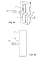
Fig. 4a is a schematic, partly sectional, perspective view and illustrates a sensor arrangement according to a second embodiment. -
Fig. 4b is a schematic, partly sectional, side view and illustrates the sensor arrangement ofFig. 4a . -
Figs. 1 and2 illustrate acone crusher 10 which is of the inertia cone crusher type. Thecone crusher 10 comprises acrusher frame 12 in which the various parts of thecrusher 10 are mounted. Theframe 12 is suspended oncushions 11 to dampen vibrations occurring during the crushing action. - The
crusher frame 12 comprises anupper frame member 14, which has the shape of a bowl, and alower frame member 16. Theupper frame member 14 is provided with anouter thread 18, which co-operates with aninner thread 20 of thelower frame member 16 in such a manner that the outer andinner threads upper frame member 14 to thelower frame member 16 in the form of a threadedengagement 19. - The
upper frame member 14 supports, on the inside thereof, anouter crushing shell 22. Thelower frame member 16 supports an inner crushing shell arrangement 24. The inner crushing shell arrangement 24 comprises a crushinghead 26, which has the shape of a cone and which supports an inner crushingshell 28. The outer and inner crushingshells gap 30, to which material that is to be crushed is supplied. - The crushing
head 26 rests on aspherical bearing 32, which is supported by thelower frame member 16. Hence, the crushinghead 26 with the inner crushingshell 28 supported thereon, is supported by thelower frame member 16. The crushinghead 26 is rotatably connected to an unbalance bushing 34, which has the shape of a cylindrical sleeve. Anunbalance weight 36 is mounted on one side of the unbalance bushing 34. At its lower end theunbalance bushing 34 is connected to adrive shaft 38 via atransmission shaft 40.Universal joints 42 of thetransmission shaft 40 allow the lower end of the unbalance bushing 34 to be displaced from a vertical axis A during operation of thecrusher 10. - When the
crusher 10 is in operation, thedrive shaft 38 is rotated by a motor in a non-illustrated manner, e.g. via a belt-and-pulley transmission 43. The rotation of thedrive shaft 38 causes the unbalance bushing 34 to rotate, and as an effect of that rotation the unbalance bushing 34 swings outwards in response to the centrifugal force to which theunbalance weight 36 is exposed. The combined rotation and swinging of the unbalance bushing 34 makes the crushinghead 26 gyrate about a vertical axis, such that material is crushed in the crushinggap 30 formed between the outer and inner crushingshells - The width of the crushing
gap 30 can be adjusted by turning theupper frame member 14, by means of thethreads shells upper frame member 14 is provided with acircumferential gear ring 44. Thegear ring 44 is in mesh with apinion 46, which is arranged to be rotated by a crushing gap adjustment motor (not shown) mounted within amotor bracket 62 fitted to thelower frame member 16. By operating the crushing gap adjustment motor, thepinion 46 turns thegear ring 44, and thereby also theupper frame member 14, such that theupper frame member 14 is vertically translated by the threadedengagement 19. Thereby, also the outer crushingshell 22 is vertically translated, such that the width of the crushinggap 30 is adjusted. - As is best illustrated in
Fig. 2 , thegear ring 44 is connected to theupper frame member 14 via keyed slidingengagements 57, which allow thegear ring 44 to remain in engagement with thepinion 46 while theupper frame member 14 is vertically translated. The keyed slidingengagements 57 are formed byvertical bars 56, attached to theupper frame member 14, which are keyed withmating notches 58 of the inner periphery of thegear ring 44. Thereby, thegear ring 44 is rotationally locked to theupper frame member 14, and may slide vertically along thebars 56. Thegear ring 44 rests and slides, when being turned, upon an upper portion of themotor support bracket 62. - Continuing with the description of
Fig. 2 , thecone crusher 10 comprises asensor arrangement 64 for measuring the vertical position of theupper frame member 14 and of the outer crushingshell 22 supported thereby. Thesensor arrangement 64 comprises asensor housing 66 which is mounted on asensor housing bracket 68 fitted to thelower frame member 16. - The
upper frame member 14 is provided with acircumferential flange 70, as will be described in more detail with reference toFigs. 3a and 3b . The outwardly projectingflange 70 is fixedly mounted to theupper frame member 14 by bolts (not shown). -
Figs. 3a and 3b illustrate in greater detail thesensor arrangement 64. Thesensor arrangement 64 comprises asensor element 72 mounted within thesensor housing 66 on a side wall thereof. Thesensor element 72 comprises an elongatevertical sensing array 74 which extends in a vertical direction. Thevertical sensing array 74 may typically have a vertical height which is in the range of 50 to 2000 mm. Thevertical sensing array 74 may typically have a horizontal width which is in the range of 0.1 to 200 mm. In this embodiment thesensor element 72 comprises an inductive position sensor. Such an inductive position sensor generates an inductive field which shifts along a sensitive surface and detects a metallic target in the detection range of the inductive field. The inductive sensor comprises several coils arranged in a coil array. Hence, in this embodiment thevertical sensing array 74 comprises a coil array. The inductive sensor calculates the current position of the target and provides output either as a distance-proportional analog signal or as a definable switching position. The inductive sensing field extends along the vertical height of thevertical sensing array 74. Thesensor element 72 is thus able to detect the vertical position along thevertical sensing array 74 of a metal target without any physical contact therewith. The sensor output is received by a control unit (not shown) connected to thesensor element 72. - The
crusher 10 comprises a target means 76 arranged to follow vertical movement of theupper frame member 14. In this embodiment the target means 76 comprises a slidingmember 78, ametallic target 80 attached to the slidingmember 78, and thecircumferential flange 70. - The sliding
member 78 is provided with ahole 82 in which a guidingrod 84 is received. The guidingrod 84 is mounted within thesensor housing 66 to guide movement of the slidingmember 78. The slidingmember 78 is arranged around the guidingrod 84 and is thus free to move in a vertical direction under the guidance of the guidingrod 84. Acompression spring 86 is arranged around the guidingrod 84 between the slidingmember 78 and a bottom plate of thesensor housing 66 to exert a vertical pressing force on the slidingmember 78. The slidingmember 78 is pressed vertically upwards and against theflange 70 and thus abuts a lower portion of the outwardly projectingflange 70. - Vertical adjustment of the
frame member 14 is achieved by rotating thegear ring 44 by means ofpinion 46 and adjustment motor, as described hereinbefore with reference toFig. 2 . In one example, starting out from the situation illustrated inFig. 3a , theupper frame member 14 is moved vertically downwards. Then theflange 70, which is rigidly attached to theupper frame member 14, is displaced downwards, as illustrated by arrow A inFig. 3b . The slidingmember 78, which abuts against a lower portion of theflange 70, then follows the vertical movement of theflange 70, as illustrated by arrow B inFig. 3b . Hence, movement of the slidingmember 78 is in this case caused by the vertical movement of theupper frame member 14 via theflange 70. - Upon adjustment of the
upper frame member 14 in a direction upwards theflange 70 is displaced upwards. The slidingmember 78, which is pressed against a lower portion of theflange 70 by thecompression spring 86, then follows the vertical movement of theflange 70 due to the spring force of thespring 86. Movement of the slidingmember 78 upwards to follow the movement of theflange 70 upon an adjustment of theupper member 14 upwards is thus caused by the force exerted on the slidingmember 78 by thecompression spring 86. Hence, the target means 76 comprising the slidingmember 78 is arranged to follow vertical movement downwards as well as upwards of theupper frame member 14. - In order to generate a sensor output the target means 76 is detectable by the inductive sensor of the
sensor element 72 along thevertical sensing array 74. To this end, the target means 76 comprises ametallic target 80, which is attached to the slidingmember 78 in such a manner that it moves with the slidingmember 78. Thevertical sensing array 74 extends in a vertical direction along at least a portion of a vertical range within which thetarget 80 may be moved upon adjusting the vertical position of theupper frame member 14. Themetallic target 80 may have a vertical height which is in the range of, for example, 2 to 25 mm. The vertical height of themetallic target 80 is adapted to the type ofsensor element 72 that is utilized. In accordance with one example, the vertical height of themetallic target 80 may be 13 mm. Thevertical sensing array 74 of thesensor element 72 may detect the vertical position of thetarget 80 with a high accuracy. In accordance with one embodiment, the slidingmember 78 is made from an isolating material, such as a plastic material, in order not to interfere with the desired electrical interference between thetarget 80 and thevertical sensing array 74 of thesensor element 72. - The guiding
rod 84 is arranged such that a constant clearance of typically about 0 to 20 mm, for example a clearance of 5 mm, is formed between themetallic target 80 and the outer surface of thesensing array 74. Hence, the horizontal distance between thetarget 80 and thesensing array 74 is substantially constant, regardless of the actual vertical position of theupper frame member 14, which provides for measuring the position of theupper frame member 14 with a high level of accuracy. - During operation of the
sensor arrangement 64, thesensor element 72 emits an alternating electro-magnetic sensing field along thesensing array 74. When themetallic target 80 enters the sensing field eddy currents are induced in thetarget 80 which reduces the signal amplitude of thesensor element 72 and triggers a change of state at thesensor element 72 output received by the control unit. In this embodiment an inductive sensor called PMI-F110 commercially available from Pepperl+Fuchs GmbH was used. - Hereinafter a crusher according to a second embodiment will be described with reference to
Figs. 4a and 4b . Many features disclosed in the first embodiment are also present in the second embodiment with similar reference numerals identifying similar or same features. Having mentioned this, the description will focus on explaining the differing features of the second embodiment. - In the second embodiment the target of the target means is formed by the
circumferential flange 70 itself. The sensor arrangement comprises aninductive sensor element 72 provided with avertical sensing array 74 which extends in vertical direction along at least a portion of a vertical range within which the target means, i.e. theflange 70, may be moved upon adjusting the vertical position of theupper frame member 14. Thesensor element 72 is arranged such that thesensing array 74 faces a front edge of theflange 70. Theflange 70 is thus detectable at different vertical positions along thevertical sensing array 74. Thesensor element 72 is arranged such that a clearance is formed between the front edge of theflange 70 and thesensing array 74, as best illustrated inFig. 4b . In this embodiment a sliding member as disclosed in the first embodiment is not needed since theflange 70 itself is detectable by thesensing array 74. - The invention has mainly been described above with reference to a few embodiments. However, as is readily appreciated by a person skilled in the art, other embodiments than the ones disclosed above are equally possible within the scope of the invention, as defined by the appended patent claims.
- For example, the invention is not limited to any particular type of cone crusher; on the contrary, it is suited for many different types of cone crushers known to those skilled in the art, such as the type of crusher having the top of a head shaft journalled in a spider assembly, as well as the type of crusher that is described in
U. S. Patent No. 1,894, 601 , occasionally called Symons type, and the inertia type of cone crushers disclosed herein, having an unbalance weight for obtaining a gyratory motion of the crushing head. - The sensor element may comprise another type of sensor than the one described hereinbefore. For instance, the sensor element may comprise a capacitive or photoelectric sensor. In case the sensor element comprises a photoelectric sensor the target means preferably comprises a plastic target.
- Hereinbefore it has been described that the
sensor element 72 is attached to thelower frame member 16 and the target means is arranged to follow the vertical movement of theupper frame member 14. In an alternative embodiment a sensor element may instead be arranged to follow the vertical movement of theupper frame member 14, e.g. by way of abutment against theflange 70. A stationary target, e.g. in the form of a circumferential rim, may then be fixedly arranged to thelower frame member 16. - Instead of a
compression spring 86 as disclosed in the first embodiment another arrangement may be used to press the slidingmember 78 against at least a portion of theflange 70. For instance, a tension spring may be used for this purpose. Then the slidingmember 78 is arranged to abut at least an upper portion of the flange. - Hereinbefore it has been described that the
circumferential flange 70 is fixedly secured to theupper frame member 14. It is realised that a circumferential flange may, as alternative, be integrally formed with theupper frame member 14. - Further objects and features of the present invention will be apparent from the following detailed description and claims.
Claims (12)
- A cone crusher comprising:an outer crushing shell (22) and an inner crushing shell (28) forming between them a crushing gap (30), the outer crushing shell (22) being supported on an upper frame member (14) in vertically adjustable engagement with a lower frame member (16), said vertically adjustable engagement being configured for adjusting the vertical position of the outer crushing shell (22) relative to the lower frame member (16) so as to permit adjustment of the width of the crushing gap (30), anda sensor arrangement (64) provided with a sensor element (72) mounted to one of the lower frame member (16) and the upper frame member (14) for measuring the vertical position of the outer crushing shell (22),characterized in further comprising a target means (76, 80; 70) arranged to be detectable by said sensor element (72), wherein one (76, 80; 70) of the target means (76, 80; 70) and the sensor element (72) being arranged to follow vertical movement of the upper frame member (14) and to move in relation to the other one (72) of the target means (76, 80; 70) and the sensor element (72),said sensor element (72) comprising a vertical sensing array (74) which extends in a vertical direction along at least a portion of a range within which the target means (76, 80; 70) may be moved upon adjusting the vertical position of the upper frame member (14), andthe target means (76, 80; 70) being detectable at different vertical positions along the vertical sensing array (74).
- A cone crusher according to claim 1, wherein the target means (76, 80; 70) comprises a circumferential flange (70).
- A cone crusher according to claim 2, wherein said circumferential flange (70) is externally arranged on the upper frame member (14) and said sensor arrangement (64) is mounted to the lower frame member (16).
- A cone crusher according to any of the preceding claims, wherein the sensing array (74) and a target (80; 70) of the target means (76, 80; 70) are arranged with a clearance therebetween.
- A cone crusher according to any of the preceding claims, wherein the sensor element (72) comprises an inductive sensor.
- A cone crusher according to any of the preceding claims, wherein the distance between the outer surface of said sensing array (74) and a target (80; 70) of said target means (76, 80; 70) is constant.
- A cone crusher according to any one of claims 2-6, wherein the target means (76, 80; 70) comprises a sliding member (78) arranged to abut at least a portion of said flange (70).
- A cone crusher according to claim 7, wherein the target means (76) comprises a resilient member (86) arranged to press the sliding member (78) against at least a portion of said flange (70).
- A cone crusher according to claim 8, wherein said resilient member (86) is a spring, such as a compression spring (86).
- A cone crusher according to any one of claims 7-9, wherein said sliding member (78) is provided with a target (80) which is detectable by the sensor element (72).
- A cone crusher according to any of the preceding claims, wherein said target means comprises a target (80; 70) formed from a magnetic metallic material, such as steel.
- A cone crusher according to claim 11, wherein the target (80) has a vertical height which is in the range of 2 to 25 mm.
Priority Applications (11)
| Application Number | Priority Date | Filing Date | Title |
|---|---|---|---|
| EP11191503.9A EP2599550B1 (en) | 2011-12-01 | 2011-12-01 | A cone crusher having an arrangement for measuring a position of a crushing shell |
| RU2014126583/13A RU2569818C1 (en) | 2011-12-01 | 2012-11-13 | Conical crusher with structure for measurement of position of crushing housing |
| CN201280059112.3A CN103958065B (en) | 2011-12-01 | 2012-11-13 | Cone crusher with arrangement for measuring the position of the crushing shell |
| BR112014013144A BR112014013144A2 (en) | 2011-12-01 | 2012-11-13 | a cone crusher having an arrangement for measuring a position of a crushing shell |
| PCT/EP2012/072519 WO2013079319A1 (en) | 2011-12-01 | 2012-11-13 | A cone crusher having an arrangement for measuring a position of a crushing shell |
| AU2012344165A AU2012344165B2 (en) | 2011-12-01 | 2012-11-13 | A cone crusher having an arrangement for measuring a position of a crushing shell |
| CA2855228A CA2855228A1 (en) | 2011-12-01 | 2012-11-13 | A cone crusher having an arrangement for measuring a position of a crushing shell |
| IN1099KON2014 IN2014KN01099A (en) | 2011-12-01 | 2012-11-13 | |
| US14/361,717 US9227191B2 (en) | 2011-12-01 | 2012-11-13 | Cone crusher having an arrangement for measuring a position of a crushing shell |
| ZA2014/03813A ZA201403813B (en) | 2011-12-01 | 2014-05-23 | A cone crusher having an arrangement for measuring a position of a crushing shell |
| CL2014001393A CL2014001393A1 (en) | 2011-12-01 | 2014-05-27 | Cone crusher comprising an external crushing housing and an internal crushing housing forming between them a crushing space, a sensor configuration provided with a sensor element mounted to one of the member of the lower structure, further comprising a blank means arranged to be detectable by said sensor. |
Applications Claiming Priority (1)
| Application Number | Priority Date | Filing Date | Title |
|---|---|---|---|
| EP11191503.9A EP2599550B1 (en) | 2011-12-01 | 2011-12-01 | A cone crusher having an arrangement for measuring a position of a crushing shell |
Publications (2)
| Publication Number | Publication Date |
|---|---|
| EP2599550A1 true EP2599550A1 (en) | 2013-06-05 |
| EP2599550B1 EP2599550B1 (en) | 2015-02-25 |
Family
ID=47146434
Family Applications (1)
| Application Number | Title | Priority Date | Filing Date |
|---|---|---|---|
| EP11191503.9A Not-in-force EP2599550B1 (en) | 2011-12-01 | 2011-12-01 | A cone crusher having an arrangement for measuring a position of a crushing shell |
Country Status (11)
| Country | Link |
|---|---|
| US (1) | US9227191B2 (en) |
| EP (1) | EP2599550B1 (en) |
| CN (1) | CN103958065B (en) |
| AU (1) | AU2012344165B2 (en) |
| BR (1) | BR112014013144A2 (en) |
| CA (1) | CA2855228A1 (en) |
| CL (1) | CL2014001393A1 (en) |
| IN (1) | IN2014KN01099A (en) |
| RU (1) | RU2569818C1 (en) |
| WO (1) | WO2013079319A1 (en) |
| ZA (1) | ZA201403813B (en) |
Cited By (1)
| Publication number | Priority date | Publication date | Assignee | Title |
|---|---|---|---|---|
| SE544105C2 (en) * | 2020-06-26 | 2021-12-21 | Metso Outotec Usa Inc | A gyratory crusher, a method for rotating an upper crusher frame and a retrofitting kit |
Families Citing this family (5)
| Publication number | Priority date | Publication date | Assignee | Title |
|---|---|---|---|---|
| CN104549623A (en) * | 2015-01-28 | 2015-04-29 | 浙江浙矿重工股份有限公司 | Top frame of cone crusher |
| CN108889424B (en) * | 2018-06-30 | 2020-04-17 | 宿州青果知识产权服务有限公司 | Graphene crusher |
| CN113649161B (en) * | 2021-08-05 | 2022-08-19 | 南昌矿机集团股份有限公司 | Intelligent monitoring and discharge opening intelligent adjusting method for wear of lining plate of cone crusher |
| CN117298948B (en) * | 2023-10-16 | 2024-05-17 | 史丹利农业集团股份有限公司 | Accurate adding equipment and method for inhibitor in stable fertilizer |
| CN117258878B (en) * | 2023-11-20 | 2024-01-16 | 德州鸿途矿山机械有限公司 | Cone crusher |
Citations (3)
| Publication number | Priority date | Publication date | Assignee | Title |
|---|---|---|---|---|
| US1894601A (en) | 1929-02-20 | 1933-01-17 | Nordberg Manufacturing Co | Crushing machine |
| US4717084A (en) * | 1986-12-22 | 1988-01-05 | Cedarapids, Inc. | Hydraulic system for remote operable cone crushers |
| US20100102152A1 (en) | 2007-01-31 | 2010-04-29 | Sandvik Intellectual Property Ab | Method for controlling process parameters of a cone crusher |
Family Cites Families (6)
| Publication number | Priority date | Publication date | Assignee | Title |
|---|---|---|---|---|
| US3908916A (en) * | 1973-06-12 | 1975-09-30 | Boris Vasilievich Klushantsev | Gyratory crusher |
| SU749429A1 (en) * | 1978-02-09 | 1980-07-23 | Всесоюзный Ордена Трудового Красного Знамени Научно-Исследовательский И Проектный Институт Механической Обработки Полезных Ископаемых | Apparatus for regulating discharge slot of cone eccentric mill |
| SU1416181A1 (en) * | 1986-12-29 | 1988-08-15 | Всесоюзный научно-исследовательский и проектный институт механической обработки полезных ископаемых "Механобр" | Apparatus for checking and regulating the angle of nutation of inertial crusher cone |
| US20070051837A1 (en) * | 2005-09-06 | 2007-03-08 | Johnson Crushers International | Rock crusher having overload detection |
| SE530883C2 (en) * | 2007-02-22 | 2008-10-07 | Sandvik Intellectual Property | Storage for a shaft in a gyratory crusher, and ways to set the crusher's gap width |
| SE532646C2 (en) * | 2008-07-04 | 2010-03-09 | Sandvik Intellectual Property | Storage for a shaft in a gyratory crusher, and ways to set the crusher's gap width |
-
2011
- 2011-12-01 EP EP11191503.9A patent/EP2599550B1/en not_active Not-in-force
-
2012
- 2012-11-13 AU AU2012344165A patent/AU2012344165B2/en not_active Ceased
- 2012-11-13 BR BR112014013144A patent/BR112014013144A2/en not_active IP Right Cessation
- 2012-11-13 RU RU2014126583/13A patent/RU2569818C1/en not_active IP Right Cessation
- 2012-11-13 CN CN201280059112.3A patent/CN103958065B/en not_active Expired - Fee Related
- 2012-11-13 US US14/361,717 patent/US9227191B2/en not_active Expired - Fee Related
- 2012-11-13 IN IN1099KON2014 patent/IN2014KN01099A/en unknown
- 2012-11-13 WO PCT/EP2012/072519 patent/WO2013079319A1/en not_active Ceased
- 2012-11-13 CA CA2855228A patent/CA2855228A1/en not_active Abandoned
-
2014
- 2014-05-23 ZA ZA2014/03813A patent/ZA201403813B/en unknown
- 2014-05-27 CL CL2014001393A patent/CL2014001393A1/en unknown
Patent Citations (3)
| Publication number | Priority date | Publication date | Assignee | Title |
|---|---|---|---|---|
| US1894601A (en) | 1929-02-20 | 1933-01-17 | Nordberg Manufacturing Co | Crushing machine |
| US4717084A (en) * | 1986-12-22 | 1988-01-05 | Cedarapids, Inc. | Hydraulic system for remote operable cone crushers |
| US20100102152A1 (en) | 2007-01-31 | 2010-04-29 | Sandvik Intellectual Property Ab | Method for controlling process parameters of a cone crusher |
Non-Patent Citations (2)
| Title |
|---|
| "Sensoren und Systeme für die Fabrikautomation", 25 October 2011, PEPPERL + FUCHS, pages: 1,6,718, XP002675473 * |
| RASNER, HORST: "Induktive Positionsmessung - berührungslos und robust", 8 December 2008 (2008-12-08), XP002675464, Retrieved from the Internet <URL:http://www.technikweblook.com/index.php?module=Pagesetter&func=viewpub&tid=5&pid=1896> [retrieved on 20120508] * |
Cited By (3)
| Publication number | Priority date | Publication date | Assignee | Title |
|---|---|---|---|---|
| SE544105C2 (en) * | 2020-06-26 | 2021-12-21 | Metso Outotec Usa Inc | A gyratory crusher, a method for rotating an upper crusher frame and a retrofitting kit |
| SE2050768A1 (en) * | 2020-06-26 | 2021-12-21 | Metso Outotec Usa Inc | A gyratory crusher, a method for rotating an upper crusher frame and a retrofitting kit |
| US12491518B2 (en) | 2020-06-26 | 2025-12-09 | Metso Usa Inc. | Gyratory crusher, a method for rotating an upper crusher frame and a retrofitting kit |
Also Published As
| Publication number | Publication date |
|---|---|
| IN2014KN01099A (en) | 2015-10-09 |
| CA2855228A1 (en) | 2013-06-06 |
| AU2012344165B2 (en) | 2016-09-29 |
| RU2569818C1 (en) | 2015-11-27 |
| CN103958065B (en) | 2015-11-25 |
| BR112014013144A2 (en) | 2017-06-13 |
| CN103958065A (en) | 2014-07-30 |
| US9227191B2 (en) | 2016-01-05 |
| AU2012344165A1 (en) | 2014-06-12 |
| US20140339347A1 (en) | 2014-11-20 |
| ZA201403813B (en) | 2016-10-26 |
| CL2014001393A1 (en) | 2015-01-16 |
| EP2599550B1 (en) | 2015-02-25 |
| WO2013079319A1 (en) | 2013-06-06 |
Similar Documents
| Publication | Publication Date | Title |
|---|---|---|
| US9227191B2 (en) | Cone crusher having an arrangement for measuring a position of a crushing shell | |
| JP6155297B2 (en) | Chute assembly for packaging equipment | |
| EP2881176B1 (en) | Cone crusher shaft position measurement sensor arrangement | |
| EP2164638B1 (en) | Measuring instrument for a gyratory crusher and method of indicating the functioning of such a crusher | |
| US20170328804A1 (en) | Centrifuge and method for sensing imbalances in the centrifuge | |
| WO2012171775A3 (en) | Tramp material indication | |
| JP2019155286A (en) | Vertical mill operation method and vertical mill | |
| CN103206908A (en) | Bearing ball installing groove detector | |
| JP5332941B2 (en) | Measuring head for inner surface inspection equipment | |
| CN215465110U (en) | System for monitoring at least one kinetic parameter of a main shaft in a crusher and crusher | |
| JP2010142933A (en) | Centering device and centering method | |
| US9923430B2 (en) | Actuator of engraving machine | |
| JP2897336B2 (en) | Deflection posture measuring device for coil spring | |
| US5150613A (en) | Material level sensing device | |
| KR100472343B1 (en) | Device sensing minute displacement of a roller for a rolling machine | |
| US7467756B2 (en) | Bowl liner movement detection method and apparatus | |
| CN113355876B (en) | Washing machine safety device, washing machine and washing machine dehydration control method | |
| CN212845445U (en) | Small acceleration sensor device | |
| EA046042B1 (en) | SYSTEM AND METHOD FOR CONTROLLING MOVEMENT OF THE CRUSHER HEAD | |
| RU2002106204A (en) | Rotation stabilization device in a rotational apparatus operating in microgravity conditions | |
| JP2009031123A (en) | Vibration sensor |
Legal Events
| Date | Code | Title | Description |
|---|---|---|---|
| PUAI | Public reference made under article 153(3) epc to a published international application that has entered the european phase |
Free format text: ORIGINAL CODE: 0009012 |
|
| 17P | Request for examination filed |
Effective date: 20111201 |
|
| AK | Designated contracting states |
Kind code of ref document: A1 Designated state(s): AL AT BE BG CH CY CZ DE DK EE ES FI FR GB GR HR HU IE IS IT LI LT LU LV MC MK MT NL NO PL PT RO RS SE SI SK SM TR |
|
| AX | Request for extension of the european patent |
Extension state: BA ME |
|
| RBV | Designated contracting states (corrected) |
Designated state(s): AL AT BE BG CH CY CZ DE DK EE ES FI FR GB GR HR HU IE IS IT LI LT LU LV MC MK MT NL NO PL PT RO RS SE SI SK SM TR |
|
| GRAP | Despatch of communication of intention to grant a patent |
Free format text: ORIGINAL CODE: EPIDOSNIGR1 |
|
| INTG | Intention to grant announced |
Effective date: 20141110 |
|
| GRAS | Grant fee paid |
Free format text: ORIGINAL CODE: EPIDOSNIGR3 |
|
| GRAA | (expected) grant |
Free format text: ORIGINAL CODE: 0009210 |
|
| AK | Designated contracting states |
Kind code of ref document: B1 Designated state(s): AL AT BE BG CH CY CZ DE DK EE ES FI FR GB GR HR HU IE IS IT LI LT LU LV MC MK MT NL NO PL PT RO RS SE SI SK SM TR |
|
| REG | Reference to a national code |
Ref country code: GB Ref legal event code: FG4D |
|
| REG | Reference to a national code |
Ref country code: CH Ref legal event code: EP |
|
| REG | Reference to a national code |
Ref country code: IE Ref legal event code: FG4D |
|
| REG | Reference to a national code |
Ref country code: DE Ref legal event code: R096 Ref document number: 602011013940 Country of ref document: DE Effective date: 20150409 |
|
| REG | Reference to a national code |
Ref country code: AT Ref legal event code: REF Ref document number: 711456 Country of ref document: AT Kind code of ref document: T Effective date: 20150415 |
|
| REG | Reference to a national code |
Ref country code: SE Ref legal event code: TRGR |
|
| REG | Reference to a national code |
Ref country code: NL Ref legal event code: VDEP Effective date: 20150225 |
|
| REG | Reference to a national code |
Ref country code: NO Ref legal event code: T2 Effective date: 20150225 |
|
| REG | Reference to a national code |
Ref country code: AT Ref legal event code: MK05 Ref document number: 711456 Country of ref document: AT Kind code of ref document: T Effective date: 20150225 |
|
| REG | Reference to a national code |
Ref country code: LT Ref legal event code: MG4D |
|
| PG25 | Lapsed in a contracting state [announced via postgrant information from national office to epo] |
Ref country code: HR Free format text: LAPSE BECAUSE OF FAILURE TO SUBMIT A TRANSLATION OF THE DESCRIPTION OR TO PAY THE FEE WITHIN THE PRESCRIBED TIME-LIMIT Effective date: 20150225 Ref country code: ES Free format text: LAPSE BECAUSE OF FAILURE TO SUBMIT A TRANSLATION OF THE DESCRIPTION OR TO PAY THE FEE WITHIN THE PRESCRIBED TIME-LIMIT Effective date: 20150225 Ref country code: LT Free format text: LAPSE BECAUSE OF FAILURE TO SUBMIT A TRANSLATION OF THE DESCRIPTION OR TO PAY THE FEE WITHIN THE PRESCRIBED TIME-LIMIT Effective date: 20150225 |
|
| PG25 | Lapsed in a contracting state [announced via postgrant information from national office to epo] |
Ref country code: GR Free format text: LAPSE BECAUSE OF FAILURE TO SUBMIT A TRANSLATION OF THE DESCRIPTION OR TO PAY THE FEE WITHIN THE PRESCRIBED TIME-LIMIT Effective date: 20150526 Ref country code: IS Free format text: LAPSE BECAUSE OF FAILURE TO SUBMIT A TRANSLATION OF THE DESCRIPTION OR TO PAY THE FEE WITHIN THE PRESCRIBED TIME-LIMIT Effective date: 20150625 Ref country code: AT Free format text: LAPSE BECAUSE OF FAILURE TO SUBMIT A TRANSLATION OF THE DESCRIPTION OR TO PAY THE FEE WITHIN THE PRESCRIBED TIME-LIMIT Effective date: 20150225 Ref country code: RS Free format text: LAPSE BECAUSE OF FAILURE TO SUBMIT A TRANSLATION OF THE DESCRIPTION OR TO PAY THE FEE WITHIN THE PRESCRIBED TIME-LIMIT Effective date: 20150225 Ref country code: LV Free format text: LAPSE BECAUSE OF FAILURE TO SUBMIT A TRANSLATION OF THE DESCRIPTION OR TO PAY THE FEE WITHIN THE PRESCRIBED TIME-LIMIT Effective date: 20150225 |
|
| PG25 | Lapsed in a contracting state [announced via postgrant information from national office to epo] |
Ref country code: NL Free format text: LAPSE BECAUSE OF FAILURE TO SUBMIT A TRANSLATION OF THE DESCRIPTION OR TO PAY THE FEE WITHIN THE PRESCRIBED TIME-LIMIT Effective date: 20150225 |
|
| PG25 | Lapsed in a contracting state [announced via postgrant information from national office to epo] |
Ref country code: CZ Free format text: LAPSE BECAUSE OF FAILURE TO SUBMIT A TRANSLATION OF THE DESCRIPTION OR TO PAY THE FEE WITHIN THE PRESCRIBED TIME-LIMIT Effective date: 20150225 Ref country code: DK Free format text: LAPSE BECAUSE OF FAILURE TO SUBMIT A TRANSLATION OF THE DESCRIPTION OR TO PAY THE FEE WITHIN THE PRESCRIBED TIME-LIMIT Effective date: 20150225 Ref country code: EE Free format text: LAPSE BECAUSE OF FAILURE TO SUBMIT A TRANSLATION OF THE DESCRIPTION OR TO PAY THE FEE WITHIN THE PRESCRIBED TIME-LIMIT Effective date: 20150225 Ref country code: SK Free format text: LAPSE BECAUSE OF FAILURE TO SUBMIT A TRANSLATION OF THE DESCRIPTION OR TO PAY THE FEE WITHIN THE PRESCRIBED TIME-LIMIT Effective date: 20150225 Ref country code: RO Free format text: LAPSE BECAUSE OF FAILURE TO SUBMIT A TRANSLATION OF THE DESCRIPTION OR TO PAY THE FEE WITHIN THE PRESCRIBED TIME-LIMIT Effective date: 20150225 |
|
| REG | Reference to a national code |
Ref country code: FR Ref legal event code: PLFP Year of fee payment: 5 |
|
| REG | Reference to a national code |
Ref country code: DE Ref legal event code: R097 Ref document number: 602011013940 Country of ref document: DE |
|
| PG25 | Lapsed in a contracting state [announced via postgrant information from national office to epo] |
Ref country code: PL Free format text: LAPSE BECAUSE OF FAILURE TO SUBMIT A TRANSLATION OF THE DESCRIPTION OR TO PAY THE FEE WITHIN THE PRESCRIBED TIME-LIMIT Effective date: 20150225 |
|
| PG25 | Lapsed in a contracting state [announced via postgrant information from national office to epo] |
Ref country code: IT Free format text: LAPSE BECAUSE OF FAILURE TO SUBMIT A TRANSLATION OF THE DESCRIPTION OR TO PAY THE FEE WITHIN THE PRESCRIBED TIME-LIMIT Effective date: 20150225 |
|
| PLBE | No opposition filed within time limit |
Free format text: ORIGINAL CODE: 0009261 |
|
| STAA | Information on the status of an ep patent application or granted ep patent |
Free format text: STATUS: NO OPPOSITION FILED WITHIN TIME LIMIT |
|
| 26N | No opposition filed |
Effective date: 20151126 |
|
| PG25 | Lapsed in a contracting state [announced via postgrant information from national office to epo] |
Ref country code: SI Free format text: LAPSE BECAUSE OF FAILURE TO SUBMIT A TRANSLATION OF THE DESCRIPTION OR TO PAY THE FEE WITHIN THE PRESCRIBED TIME-LIMIT Effective date: 20150225 |
|
| PG25 | Lapsed in a contracting state [announced via postgrant information from national office to epo] |
Ref country code: BE Free format text: LAPSE BECAUSE OF FAILURE TO SUBMIT A TRANSLATION OF THE DESCRIPTION OR TO PAY THE FEE WITHIN THE PRESCRIBED TIME-LIMIT Effective date: 20150225 |
|
| PG25 | Lapsed in a contracting state [announced via postgrant information from national office to epo] |
Ref country code: LU Free format text: LAPSE BECAUSE OF FAILURE TO SUBMIT A TRANSLATION OF THE DESCRIPTION OR TO PAY THE FEE WITHIN THE PRESCRIBED TIME-LIMIT Effective date: 20151201 Ref country code: MC Free format text: LAPSE BECAUSE OF FAILURE TO SUBMIT A TRANSLATION OF THE DESCRIPTION OR TO PAY THE FEE WITHIN THE PRESCRIBED TIME-LIMIT Effective date: 20150225 |
|
| REG | Reference to a national code |
Ref country code: CH Ref legal event code: PL |
|
| REG | Reference to a national code |
Ref country code: IE Ref legal event code: MM4A |
|
| PG25 | Lapsed in a contracting state [announced via postgrant information from national office to epo] |
Ref country code: CH Free format text: LAPSE BECAUSE OF NON-PAYMENT OF DUE FEES Effective date: 20151231 Ref country code: LI Free format text: LAPSE BECAUSE OF NON-PAYMENT OF DUE FEES Effective date: 20151231 Ref country code: IE Free format text: LAPSE BECAUSE OF NON-PAYMENT OF DUE FEES Effective date: 20151201 |
|
| REG | Reference to a national code |
Ref country code: FR Ref legal event code: PLFP Year of fee payment: 6 |
|
| PGFP | Annual fee paid to national office [announced via postgrant information from national office to epo] |
Ref country code: DE Payment date: 20161123 Year of fee payment: 6 Ref country code: GB Payment date: 20161130 Year of fee payment: 6 Ref country code: FR Payment date: 20161111 Year of fee payment: 6 Ref country code: NO Payment date: 20161212 Year of fee payment: 6 Ref country code: FI Payment date: 20161212 Year of fee payment: 6 |
|
| PGFP | Annual fee paid to national office [announced via postgrant information from national office to epo] |
Ref country code: SE Payment date: 20161213 Year of fee payment: 6 |
|
| PGFP | Annual fee paid to national office [announced via postgrant information from national office to epo] |
Ref country code: TR Payment date: 20161122 Year of fee payment: 6 |
|
| PG25 | Lapsed in a contracting state [announced via postgrant information from national office to epo] |
Ref country code: BG Free format text: LAPSE BECAUSE OF FAILURE TO SUBMIT A TRANSLATION OF THE DESCRIPTION OR TO PAY THE FEE WITHIN THE PRESCRIBED TIME-LIMIT Effective date: 20150225 Ref country code: SM Free format text: LAPSE BECAUSE OF FAILURE TO SUBMIT A TRANSLATION OF THE DESCRIPTION OR TO PAY THE FEE WITHIN THE PRESCRIBED TIME-LIMIT Effective date: 20150225 Ref country code: HU Free format text: LAPSE BECAUSE OF FAILURE TO SUBMIT A TRANSLATION OF THE DESCRIPTION OR TO PAY THE FEE WITHIN THE PRESCRIBED TIME-LIMIT; INVALID AB INITIO Effective date: 20111201 |
|
| PG25 | Lapsed in a contracting state [announced via postgrant information from national office to epo] |
Ref country code: CY Free format text: LAPSE BECAUSE OF FAILURE TO SUBMIT A TRANSLATION OF THE DESCRIPTION OR TO PAY THE FEE WITHIN THE PRESCRIBED TIME-LIMIT Effective date: 20150225 |
|
| PG25 | Lapsed in a contracting state [announced via postgrant information from national office to epo] |
Ref country code: MT Free format text: LAPSE BECAUSE OF FAILURE TO SUBMIT A TRANSLATION OF THE DESCRIPTION OR TO PAY THE FEE WITHIN THE PRESCRIBED TIME-LIMIT Effective date: 20150225 |
|
| PG25 | Lapsed in a contracting state [announced via postgrant information from national office to epo] |
Ref country code: PT Free format text: LAPSE BECAUSE OF FAILURE TO SUBMIT A TRANSLATION OF THE DESCRIPTION OR TO PAY THE FEE WITHIN THE PRESCRIBED TIME-LIMIT Effective date: 20150225 Ref country code: MK Free format text: LAPSE BECAUSE OF FAILURE TO SUBMIT A TRANSLATION OF THE DESCRIPTION OR TO PAY THE FEE WITHIN THE PRESCRIBED TIME-LIMIT Effective date: 20150225 |
|
| REG | Reference to a national code |
Ref country code: DE Ref legal event code: R119 Ref document number: 602011013940 Country of ref document: DE |
|
| REG | Reference to a national code |
Ref country code: NO Ref legal event code: MMEP |
|
| PG25 | Lapsed in a contracting state [announced via postgrant information from national office to epo] |
Ref country code: FI Free format text: LAPSE BECAUSE OF NON-PAYMENT OF DUE FEES Effective date: 20171201 |
|
| GBPC | Gb: european patent ceased through non-payment of renewal fee |
Effective date: 20171201 |
|
| PG25 | Lapsed in a contracting state [announced via postgrant information from national office to epo] |
Ref country code: SE Free format text: LAPSE BECAUSE OF NON-PAYMENT OF DUE FEES Effective date: 20171202 |
|
| REG | Reference to a national code |
Ref country code: FR Ref legal event code: ST Effective date: 20180831 |
|
| PG25 | Lapsed in a contracting state [announced via postgrant information from national office to epo] |
Ref country code: FR Free format text: LAPSE BECAUSE OF NON-PAYMENT OF DUE FEES Effective date: 20180102 Ref country code: NO Free format text: LAPSE BECAUSE OF NON-PAYMENT OF DUE FEES Effective date: 20171231 Ref country code: DE Free format text: LAPSE BECAUSE OF NON-PAYMENT OF DUE FEES Effective date: 20180703 Ref country code: AL Free format text: LAPSE BECAUSE OF FAILURE TO SUBMIT A TRANSLATION OF THE DESCRIPTION OR TO PAY THE FEE WITHIN THE PRESCRIBED TIME-LIMIT Effective date: 20150225 |
|
| PG25 | Lapsed in a contracting state [announced via postgrant information from national office to epo] |
Ref country code: GB Free format text: LAPSE BECAUSE OF NON-PAYMENT OF DUE FEES Effective date: 20171201 |
|
| PG25 | Lapsed in a contracting state [announced via postgrant information from national office to epo] |
Ref country code: TR Free format text: LAPSE BECAUSE OF NON-PAYMENT OF DUE FEES Effective date: 20171201 |