EP2599539B1 - Steam permselective membrane, and method using same for separating steam from mixed gas - Google Patents
Steam permselective membrane, and method using same for separating steam from mixed gas Download PDFInfo
- Publication number
- EP2599539B1 EP2599539B1 EP11812489.0A EP11812489A EP2599539B1 EP 2599539 B1 EP2599539 B1 EP 2599539B1 EP 11812489 A EP11812489 A EP 11812489A EP 2599539 B1 EP2599539 B1 EP 2599539B1
- Authority
- EP
- European Patent Office
- Prior art keywords
- steam
- membrane
- hydrophilic polymer
- permselective membrane
- compound
- Prior art date
- Legal status (The legal status is an assumption and is not a legal conclusion. Google has not performed a legal analysis and makes no representation as to the accuracy of the status listed.)
- Active
Links
Images





Classifications
-
- B—PERFORMING OPERATIONS; TRANSPORTING
- B01—PHYSICAL OR CHEMICAL PROCESSES OR APPARATUS IN GENERAL
- B01D—SEPARATION
- B01D71/00—Semi-permeable membranes for separation processes or apparatus characterised by the material; Manufacturing processes specially adapted therefor
- B01D71/06—Organic material
-
- B—PERFORMING OPERATIONS; TRANSPORTING
- B01—PHYSICAL OR CHEMICAL PROCESSES OR APPARATUS IN GENERAL
- B01D—SEPARATION
- B01D71/00—Semi-permeable membranes for separation processes or apparatus characterised by the material; Manufacturing processes specially adapted therefor
- B01D71/06—Organic material
- B01D71/30—Polyalkenyl halides
- B01D71/32—Polyalkenyl halides containing fluorine atoms
-
- B—PERFORMING OPERATIONS; TRANSPORTING
- B01—PHYSICAL OR CHEMICAL PROCESSES OR APPARATUS IN GENERAL
- B01D—SEPARATION
- B01D53/00—Separation of gases or vapours; Recovering vapours of volatile solvents from gases; Chemical or biological purification of waste gases, e.g. engine exhaust gases, smoke, fumes, flue gases, aerosols
- B01D53/22—Separation of gases or vapours; Recovering vapours of volatile solvents from gases; Chemical or biological purification of waste gases, e.g. engine exhaust gases, smoke, fumes, flue gases, aerosols by diffusion
- B01D53/228—Separation of gases or vapours; Recovering vapours of volatile solvents from gases; Chemical or biological purification of waste gases, e.g. engine exhaust gases, smoke, fumes, flue gases, aerosols by diffusion characterised by specific membranes
-
- B—PERFORMING OPERATIONS; TRANSPORTING
- B01—PHYSICAL OR CHEMICAL PROCESSES OR APPARATUS IN GENERAL
- B01D—SEPARATION
- B01D53/00—Separation of gases or vapours; Recovering vapours of volatile solvents from gases; Chemical or biological purification of waste gases, e.g. engine exhaust gases, smoke, fumes, flue gases, aerosols
- B01D53/26—Drying gases or vapours
- B01D53/268—Drying gases or vapours by diffusion
-
- B—PERFORMING OPERATIONS; TRANSPORTING
- B01—PHYSICAL OR CHEMICAL PROCESSES OR APPARATUS IN GENERAL
- B01D—SEPARATION
- B01D61/00—Processes of separation using semi-permeable membranes, e.g. dialysis, osmosis or ultrafiltration; Apparatus, accessories or auxiliary operations specially adapted therefor
- B01D61/36—Pervaporation; Membrane distillation; Liquid permeation
- B01D61/363—Vapour permeation
-
- B—PERFORMING OPERATIONS; TRANSPORTING
- B01—PHYSICAL OR CHEMICAL PROCESSES OR APPARATUS IN GENERAL
- B01D—SEPARATION
- B01D69/00—Semi-permeable membranes for separation processes or apparatus characterised by their form, structure or properties; Manufacturing processes specially adapted therefor
- B01D69/14—Dynamic membranes
- B01D69/141—Heterogeneous membranes, e.g. containing dispersed material; Mixed matrix membranes
- B01D69/142—Heterogeneous membranes, e.g. containing dispersed material; Mixed matrix membranes with "carriers"
-
- B—PERFORMING OPERATIONS; TRANSPORTING
- B01—PHYSICAL OR CHEMICAL PROCESSES OR APPARATUS IN GENERAL
- B01D—SEPARATION
- B01D71/00—Semi-permeable membranes for separation processes or apparatus characterised by the material; Manufacturing processes specially adapted therefor
- B01D71/02—Inorganic material
-
- B—PERFORMING OPERATIONS; TRANSPORTING
- B01—PHYSICAL OR CHEMICAL PROCESSES OR APPARATUS IN GENERAL
- B01D—SEPARATION
- B01D71/00—Semi-permeable membranes for separation processes or apparatus characterised by the material; Manufacturing processes specially adapted therefor
- B01D71/06—Organic material
- B01D71/76—Macromolecular material not specifically provided for in a single one of groups B01D71/08 - B01D71/74
- B01D71/82—Macromolecular material not specifically provided for in a single one of groups B01D71/08 - B01D71/74 characterised by the presence of specified groups, e.g. introduced by chemical after-treatment
-
- B—PERFORMING OPERATIONS; TRANSPORTING
- B01—PHYSICAL OR CHEMICAL PROCESSES OR APPARATUS IN GENERAL
- B01D—SEPARATION
- B01D2256/00—Main component in the product gas stream after treatment
- B01D2256/22—Carbon dioxide
-
- B—PERFORMING OPERATIONS; TRANSPORTING
- B01—PHYSICAL OR CHEMICAL PROCESSES OR APPARATUS IN GENERAL
- B01D—SEPARATION
- B01D2257/00—Components to be removed
- B01D2257/80—Water
-
- B—PERFORMING OPERATIONS; TRANSPORTING
- B01—PHYSICAL OR CHEMICAL PROCESSES OR APPARATUS IN GENERAL
- B01D—SEPARATION
- B01D2323/00—Details relating to membrane preparation
- B01D2323/30—Cross-linking
Definitions
- the present invention relates to a steam permselective membrane, and a method for separating steam from a mixed gas using the membrane.
- Patent Literature 1 As a method for selectively separating steam from a mixed gas including steam, there has been suggested a method of using a separating membrane having a gel layer produced from an organic metal compound or an inorganic metal compound, as a steam permselective membrane (Patent Literature 1).
- an object of the present invention is to provide a steam permselective membrane which is capable of permeating steam with a high permeation rate and high selectivity.
- a steam permselective membrane comprising a gel-like hydrophilic polymer layer comprising: crosslinked hydrophilic polymer containing a polyvinyl alcohol-polyacrylic acid salt copolymer; and at least one kind of alkali metal compound selected from the group consisting of a cesium compound, a potassium compound and a rubidium compound, wherein said alkali metal compound is a hydroxide, a carbonate, a nitrate, a carboxylate or a chloride, and wherein the hydrophilic polymer layer is a hydrogel in which the hydrophilic polymer is crosslinked and forms a three-dimensional network structure, and
- steam permeation is enabled with a high permeation rate and high selectivity.
- the alkali metal compound includes at least one kind of alkali metal compound selected from the group consisting of a cesium compound, a potassium compound, and a rubidium compound.
- the alkali metal compound includes a cesium compound
- the concentration of cesium based on the total mass of the hydrophilic polymer and the alkali metal compound is 0.001 or more and 0.003 mol/g or less.
- the alkali metal compound includes a potassium compound and/or a rubidium compound
- the total concentration of potassium and rubidium based on the total mass of the hydrophilic polymer and the alkali metal compound is 0.001 or more and 0.005 mol/g or less.
- the present invention relates to a method for selectively separating steam from a mixed gas including steam and CO 2 gas, the method comprising the step of separating the steam from the mixed gas by causing the steam in the mixed gas containing steam to permeate through a steam permselective membrane, wherein the steam permselective membrane comprises a gel-like hydrophilic polymer layer comprising a crosslinked hydrophilic polymer containing a polyvinyl alcohol-polyacrylic acid salt copolymer for selectively separating steam from a mixed gas including steam and CO 2 gas, and the hydrophilic polymer layer is a hydrogel in which the hydrophilic polymer is crosslinked and forms a three-dimensional network structure, wherein the steam permselective membrane further comprises at least one kind of alkali metal compound selected from the group consisting of a cesium compound, a potassium compound and a rubidium compound, and said alkali metal compound is a hydroxide, a carbonate, a nitrate,
- the steam permeate through the steam permselective membrane by supplying a mixed gas containing steam to one surface side of the steam permselective membrane, and reducing the partial pressure of steam on the other surface side of the steam permselective membrane to less than the partial pressure of steam in the mixed gas.
- the partial pressure of steam on the other surface side of the steam permselective membrane may be reduced to less than the partial pressure of steam in the mixed gas without substantially using a sweep gas.
- steam may be separated from a mixed gas containing steam with a high permeation rate and high selectivity.
- the method according to the present invention is particularly useful in the case of separating steam from a mixed gas containing steam and CO 2 gas.
- the steam permselective membrane according to the present invention When the steam permselective membrane according to the present invention is used, steam permeation is enabled with a high permeation rate and high selectivity.
- the steam permselective membrane of the present invention can exhibit a high permeation rate and high selectivity even at a high temperature exceeding 100°C.
- the steam permselective membrane according to the present invention is an organic membrane, and as compared with inorganic membranes, the steam permselective membrane is advantageous in that molding processing is easy, and the cost per unit membrane area is low.
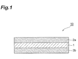
- FIG. 1 is a cross-sectional diagram showing an exemplary embodiment of a membrane laminate including a steam permselective membrane.
- the membrane laminate 10 illustrated in FIG. 1 is composed of a steam permselective membrane 1, and porous membranes 2a and 2b that are provided on both sides of the steam permselective membrane 1.
- the steam permselective membrane 1 has a gel-like hydrophilic polymer layer containing a crosslinked hydrophilic polymer.
- the hydrophilic polymer layer is a hydrogel in which hydrophilic polymer is crosslinked and forms a three-dimensional network structure.
- a hydrogel often has a property of swelling by absorbing water.
- the hydrophilic polymer contains a polyvinyl alcohol-polyacrylic acid salt copolymer (PVA-PAA salt copolymer) and is selected from, for example, a polyvinyl alcohol-polyacrylic acid salt copolymer (PVA-PAA salt copolymer), polyvinyl alcohol, polyacrylic acid, chitosan, polyvinylamine, polyallylamine, and polyvinylpyrrolidone.
- PVA-PAA salt copolymer polyvinyl alcohol-polyacrylic acid salt copolymer
- PVA-PAA salt copolymer polyvinyl alcohol, polyacrylic acid, chitosan, polyvinylamine, polyallylamine, and polyvinylpyrrolidone.
- the degree of crosslinking of the hydrogel of a PVA-PAA salt copolymer and the degree of crosslinking of the hydrogel of polyvinyl alcohol may be further adjusted by a dialdehyde compound such as glutaraldehyde, and/or an aldehyde compound such as formaldehyde.
- a PVA-PAA salt copolymer is also known as a PVA-PAA copolymer to those ordinarily skilled in the art.
- the hydrophilic polymer layer contains at least one kind of alkali metal compound selected from the group consisting of a cesium compound, a potassium compound and a rubidium compound.
- This alkali metal compound functions as a carrier that promotes selective permeation of moisture.
- the alkali metal compound is a hydroxide, a carbonate, a nitrate, a carboxylate (such as an acetate), or a chloride of an alkali metal selected from cesium (Cs), potassium (K) and rubidium (Rb).
- the hydrophilic polymer layer may further contain a lithium compound and/or a sodium compound, in addition to the alkali metal compound selected from a cesium compound, a potassium compound and a rubidium compound.
- the concentration of cesium based on the total mass of the hydrophilic polymer and the alkali metal compound is 0.003 mol/g or less.
- the alkali metal compound includes a potassium compound and/or a rubidium compound
- the total concentration of potassium and rubidium based on the total mass of the hydrophilic polymer and the alkali metal compound is 0.005 mol/g or less.
- concentrations of the alkali metals in the steam permselective membrane are in these value ranges, permeation of steam is enabled with higher selectivity to CO 2 .
- the mass of the lithium compound and the sodium compound is not included in the total mass of the alkali metal compound.
- the lower limit of the concentration of the at least one kind of alkali metal selected from the group consisting of a cesium compound, a potassium compound and a rubidium compound but the lower limit is 0.001 mol/g or higher based on the total mass of the hydrophilic polymer and the alkali metal compound.
- the steam permselective membrane 1 may have a hydrophilic polymer layer containing an uncrosslinked hydrophilic polymer and at least one kind of alkali metal compound selected from the group consisting of a cesium compound, a potassium compound and a rubidium compound.
- the hydrophilic polymer used in this case is selected from, for example, polyvinyl alcohol, polyacrylic acid, chitosan, polyvinylamine, polyallylamine, and polyvinylpyrrolidone.
- the alkali metal compound those described above may be used.
- the preferred concentration range of the alkali metal is also the same as described above.
- the steam permselective membrane 1 be composed of the hydrophilic polymer layer and a porous membrane, and at least a portion of the hydrophilic polymer layer is filled into the porous membrane.
- This porous membrane is preferably hydrophilic.
- a hydrophilic porous membrane include a hydrophilized polytetrafluoroethylene porous membrane (hydrophilic PTFE porous membrane), and a hydrophilic ceramic porous membrane (such as an alumina porous membrane).
- the porous membranes 2a and 2b are preferably hydrophobic.
- a hydrophobic porous membrane include a polytetrafluoroethylene porous membrane that is not hydrophilized (hydrophobic PTFE porous membrane).
- the porous membranes 2a and 2b may not necessarily be provided.
- the membrane laminate 10 may be produced by, for example, a method which comprises a step of preparing a cast solution containing a hydrophilic polymer, together with optionally an alkali metal compound, and water that dissolves these components; a step of forming a film of the cast solution on one of the porous membranes, porous membrane 2a; a step of drying the film of the cast solution to form a hydrophilic polymer layer; and a step of providing the other one of the porous membranes, porous membrane 2b, on the hydrophilic polymer layer.
- the cast solution may be prepared by dissolving a hydrophilic polymer and an alkali metal compound in water.
- the hydrophilic polymer may be chemically crosslinked by adding a crosslinking agent such as glutaraldehyde to the cast solution. In order to carry out crosslinking of the hydrophilic polymer, the cast solution is heated as necessary.
- a film of the cast solution may be formed by casting the casting solution. Casting may be carried out by a conventional method of using an applicator. When a hydrophilic porous membrane is placed on a hydrophobic porous membrane 2a, and the cast solution is cast on the hydrophilic porous membrane, a portion of the cast solution is filled into the hydrophilic porous membrane.
- hydrophilic polymer By removing water from the film of the cast solution, a gel-like hydrophilic polymer layer is formed. Thereafter, the hydrophilic polymer may be further crosslinked by heating.
- a porous membrane 2b is laminated on the steam permselective membrane 1 having a hydrophilic polymer layer, and thus a membrane laminate 10 is obtained.
- the membrane laminate according to the present exemplary embodiment may be used to separate steam from a mixed gas containing steam and other gases.
- a mixed gas containing steam is supplied to the side of the porous membrane 2a (feed side), steam is caused to permeate through the steam permselective membrane 1, and thereby the permeated steam is separated into the side of the porous membrane 2b.
- Steam may be permeated efficiently through the steam permselective membrane 1 by reducing the partial pressure of steam on the opposite side of the porous membrane 2a of the membrane laminate 10, to be lower than the partial pressure of steam in the mixed gas that is supplied to the side of the porous membrane 2a.
- a sweep gas such as Ar gas may be continuously supplied to the side of the porous membrane 2b.
- the partial pressure difference of steam may be adjusted by a method of setting the total pressure on the side of the porous membrane 2a to be higher than the total pressure on the side of the porous membrane 2b.
- the steam permselective membrane 1 may also be used for applications other than reutilization of steam, such as dehumidification of a mixed gas.
- the steam permselective membrane 1 is preferably heated to 100°C to 200°C.
- the steam permselective membrane according to the present exemplary embodiment may exhibit high steam permeability and high steam selectivity even at such a high temperature. Therefore, it is possible to recover and reutilize steam at a high temperature, without liquefying the steam by cooling. According to this method, latent heat of steam may be effectively utilized, as compared with the case of heating again the water that has been liquefied by cooling, and reutilizing the water as steam, and therefore, higher energy efficiency may be realized. Meanwhile, when the steam that has permeated through the steam permselective membrane is not reutilized as steam, or in similar cases, the recovered steam may be recovered by liquefying the steam by cooling.
- the steam permselective membrane 1 is used particularly suitably to separate steam from a mixed gas containing steam and CO 2 .
- allowing CO 2 gas in a raw material gas containing CO 2 gas to permeate through a CO 2 permselective membrane, and thereby recovering the permeated CO 2 gas together with steam as a sweep gas; allowing steam in a mixed gas containing steam and CO 2 gas to permeate through a steam permselective membrane, and thereby separating steam from the mixed gas; and reutilizing the separated steam as a sweep gas may be combined.
- CO 2 may be recovered from a gas containing CO 2 with high energy efficiency.
- the steam permselective membrane may be formed into a cylindrical shape.
- FIG. 2 is a cross-sectional diagram showing an exemplary embodiment of a gas treating apparatus including a cylindrical-shaped steam permselective membrane.
- FIG. 2(a) illustrates a cross-section that is perpendicular to the longitudinal direction of the gas treating apparatus
- FIG. 2(b) illustrates a cross-section that is parallel to the longitudinal direction of the gas treating apparatus.
- the gas treating apparatus 20 illustrated in FIG. 2 includes a cylindrical-shaped steam permselective membrane 1, and a cylindrical-shaped container 5 that accommodates the steam permselective membrane 1.
- the steam permselective membrane 1 is composed of a cylindrical-shaped hydrophilic polymer layer 3 and a cylindrical-shaped porous membrane 4 provided inside the cylindrical-shaped polymer layer.
- a portion of the hydrophilic polymer layer 3 is filled into the porous membrane 4.
- the hydrophilic polymer layer 3 and the porous membrane 4 in FIG. 2 may be respectively formed from the same materials as those of the hydrophilic polymer layer and the porous membrane that constitute the steam permselective membrane 1 of FIG. 1 .
- the hydrophilic polymer layer 3 may be supported on the inner peripheral surface side of the porous membrane 4.
- the cross-sectional shape of the cylindrical-shaped steam permselective membrane is not necessarily perfect circle, and modification into any arbitrary shape such as an elliptical shape may be made.
- the steam permselective membrane 1 divides the interior of the container 5, and thereby a feed-side space 11 into which a mixed gas 30 containing steam flows, and a sweep-side space 12 containing a discharge gas 35 containing steam that has permeated through the steam permselective membrane 1 are formed.
- the container 5 has an opening 21 provided at one end, which makes the feed-side space 11 open into the outside of the container 5, and provided at the other end, an opening 21 which makes the feed-side space 11 open into the outside of the container 5 and an opening 25 which makes the seep-side space 12 open into the outside of the container 5.
- the mixed gas 30 is supplied to the feed-side space 11 through the opening 21, and is discharged through the opening 22.
- the steam that has been separated from the mixed gas 30 by permeating through the steam permselective membrane 1, is collected into the discharge gas 35 that is discharged through the opening 25. It is also acceptable to allow a steam gas to flow into the sweep-side space 12 as described above.
- SS gel a PVA-PAA salt copolymer (manufactured by Sumitomo Seika Chemicals Co., Ltd.; hereinafter, referred to as "SS gel") was dissolved in 80.0 g of ion-exchanged water at room temperature. 0.064 g of a 25% by mass aqueous solution of glutaraldehyde was added to the SS gel solution thus obtained. Subsequently, the solution was heated at 95°C for 12 hours to carry out chemical crosslinking by glutaraldehyde, and thus a cast solution was obtained.
- SS gel a PVA-PAA salt copolymer manufactured by Sumitomo Seika Chemicals Co., Ltd.
- a hydrophobic PTFE porous membrane (manufactured by Sumitomo Electric Industries, Ltd., Fluoropore FP-010) was mounted on a glass plate, and a hydrophilic PTFE porous membrane (manufactured by Sumitomo Electric Industries, Ltd., WPW-020-80) was mounted thereon.
- the cast solution was cast on the hydrophilic PTFE porous membrane to a thickness of 500 ⁇ m by using a baker applicator. At this time, a portion of the cast solution was filled into the hydrophilic PTFE porous membrane. Thereafter, the cast solution thus cast was dried for about 12 hours in a dry box that was maintained at a humidity of about 5%, and thereby a gel layer was formed.
- the gel layer thus formed was placed, together with the glass plate, in a constant temperature chamber that was maintained at 120°C, and thermal crosslinking was carried out for 2 hours.
- a steam permselective membrane composed of a hydrophilic PTFE porous membrane and a gel layer was formed.
- a hydrophobic PTFE porous membrane was laminated on the steam permselective membrane, and thus a membrane laminate having a three-layer configuration of hydrophobic PTFE porous membrane/steam permselective membrane/hydrophobic PTFE porous membrane was obtained.
- SS gel a PVA-PAA salt copolymer
- SS gel a PVA-PAA salt copolymer
- 0.064 g of a 25% by mass aqueous solution of glutaraldehyde was added to the aqueous SS gel solution thus obtained.
- the solution was heated at 95°C for 12 hours to thereby carry out chemical crosslinking by glutaraldehyde.
- CsOH was added to the solution as a carrier, CsOH was dissolved therein, and thus a cast solution was obtained.
- the amount of CsOH was adjusted such that the concentration of CsOH relative to the total mass of the SS gel and CsOH would be 30% by mass.
- the molar concentration of Cs was 0.002 mol/g based on the total mass of the SS gel and CsOH.
- a hydrophobic PTFE porous membrane (manufactured by Sumitomo Electric Industries, Ltd.; Fluoropore FP-010) was mounted on a glass plate, and a hydrophilic PTFE porous membrane (manufactured by Sumitomo Electric Industries, Ltd.; WPW-020-80) was mounted thereon.
- the cast solution was cast on the hydrophilic PTFE porous membrane to a thickness of 500 ⁇ m by using a baker applicator. Thereafter, the cast solution thus cast was dried for about 12 hours in a dry box that was maintained at a humidity of about 5%, and thereby a gel layer was formed.
- the gel layer thus formed was placed, together with the glass plate, in a constant temperature chamber that was maintained at 120°C, and thermal crosslinking was carried out for 2 hours.
- a steam permselective membrane composed of a hydrophilic PTFE porous membrane and a gel layer was formed.
- a hydrophobic PTFE porous membrane was laminated on the steam permselective membrane, and thus a membrane laminate having a three-layer configuration of hydrophobic PTFE porous membrane/steam permselective membrane/hydrophobic PTFE porous membrane was obtained.
- a hydrophobic PTFE porous membrane (manufactured by Sumitomo Electric Industries, Ltd.; Fluoropore FP-010) was mounted on a glass plate, and a hydrophilic PTFE porous membrane (manufactured by Sumitomo Electric Industries, Ltd.; WPW-020-80) was mounted thereon.
- the cast solution was cast on the hydrophilic PTFE porous membrane to a thickness of 500 ⁇ m by using a baker applicator. Thereafter, the cast solution thus cast was dried for about 12 hours in a dry box that was maintained at a humidity of about 5%, and thereby a steam permselective membrane composed of a hydrophilic PTFE porous membrane and a PVA layer was formed.
- hydrophobic PTFE porous membrane was laminated on the steam permselective membrane, and thus a membrane laminate having a three-layer configuration of hydrophobic PTFE porous membrane/steam permselective membrane/hydrophobic PTFE porous membrane was obtained.
- a hydrophobic PTFE porous membrane (manufactured by Sumitomo Electric Industries, Ltd.; Fluoropore FP-010) was mounted on a glass plate, and a hydrophilic PTFE porous membrane (manufactured by Sumitomo Electric Industries, Ltd.; WPW-020-80) was mounted thereon.
- a 5% by mass aqueous PVA solution was cast on the hydrophilic PTFE porous membrane to a thickness of 500 ⁇ m by using a baker applicator.
- the aqueous PVA solution thus cast was dried for about 12 hours in a dry box that was maintained at a humidity of about 5%, and thereby, a steam permselective membrane composed of a hydrophilic PTFE porous membrane and a PVA layer was formed. Furthermore, a hydrophobic PTFE porous membrane was laminated on the steam permselective membrane, and thus a membrane laminate having a three-layer configuration of hydrophobic PTFE porous membrane/steam permselective membrane/hydrophobic PTFE porous membrane was obtained.
- a membrane laminate was mounted on a membrane evaluation apparatus, and an evaluation of gas permeation performance was carried out. While the membrane laminate was heated to a predetermined temperature, a raw material gas containing CO 2 , N 2 and H 2 O (steam) was supplied to one of the surface sides (feed side) of the membrane laminate, and Ar gas as a sweep gas was caused to flow to the opposite side of the feed side (sweep side). Water was recovered from a discharge gas including the gas that had permeated from the feed side to the sweep side and the Ar gas, by using a cooling trap, and the amount of recovered water was quantitatively determined at a constant time interval.
- a raw material gas containing CO 2 , N 2 and H 2 O (steam) was supplied to one of the surface sides (feed side) of the membrane laminate, and Ar gas as a sweep gas was caused to flow to the opposite side of the feed side (sweep side). Water was recovered from a discharge gas including the gas that had permeated from the feed side to the sweep side and the Ar gas, by using
- the steam permeance [mol/(m 2 ⁇ s ⁇ kPa)] of the membrane which is an index of the steam permeation rate, was calculated based on the amounts thus determined.
- the composition of the remaining discharge gas was quantitatively determined by gas chromatography, and from these results and the flow rate of Ar gas, the CO 2 permeance [mol/(m 2 ⁇ s ⁇ kPa)] of the membrane was calculated.
- the ratio of the steam permeance to the CO 2 permeance steam permeance/CO 2 permeance
- the evaluation conditions of the gas permeation performance are presented in the following table.
- FIG. 3 is a graph showing the relation between the steam permeance and temperature, and the relation between the steam/CO 2 selectivity and temperature, in the various membranes of SS gel only, SS gel/CsOH, PVA/CsOH, and PVA only. All of the membranes of SS gel only, SS gel/CsOH, and PVA/CsOH exhibited high steam permeance as compared with the membrane for comparison formed of PVA only. All of the membranes exhibited steam/CO 2 selectivity to a certain degree or higher, and it was confirmed that all of the membranes may be used as steam permselective membranes. Among them, the membrane using SS gel exhibited particularly high steam/CO 2 selectivity in a high temperature region.
- Membrane laminates each including a steam permselective membrane containing a carrier and the SS gel at the concentrations indicated in the following various tables, were produced by the same procedure as that used in Study 1, by using CsOH, CS 2 CO 3 , CsNO 3 , CH 3 COOCs or CsCl as the carrier.
- the Cs concentration was the proportion of the mole number of Cs relative to the total mass (g) of the SS gel and the carrier (CsOH)
- the carrier concentration was the proportion of the mass of the carrier relative to the total mass of the SS gel and the carrier.
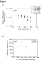
- FIGS. 4 , 5 , 6 , 7 and 8 are graphs respectively showing the relation between the steam permeance and temperature and the relation between the steam/CO 2 selectivity and the Cs concentration for the membranes that used CsOH, Cs 2 CO 3 , CsNO 3 , CH 3 COOCs and CsCl as carriers. Since all of the membranes exhibited high steam permeance and high steam/CO 2 selectivity, it was confirmed that the various Cs compounds were useful as carriers for enhancing the permeation performance. When the Cs concentration increases to a certain degree, a tendency that the steam/CO 2 selectivity decreases was recognized, but selectivity was maintained to the extent that steam could be selectively permeated.
- Membrane laminates each including a steam permselective membrane containing a carrier and the SS gel at the concentrations indicated in the following various tables, were produced by the same procedure as that used in Study 1, by using KOH, K 2 CO 3 , RbOH or Rb 2 CO 3 as the carrier.
- the amount of carrier means the amount of KOH, K 2 CO 3 , RbOH or Rb 2 CO 3
- the K concentration or the like means the proportion of the mole number of K or the like relative to the total mass (g) of the SS gel and the carrier (KOH or the like)
- the carrier concentration means the proportion of the mass of the carrier relative to the total mass of the SS gel and the carrier (KOH or the like).
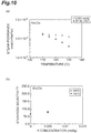
- FIGS. 9 , 10 , 11 , and 12 are graphs respectively showing the relation between the steam permeance and temperature and the relation between the steam/CO 2 selectivity and the Cs concentration for the membranes that used KOH, K 2 CO 3 , RbOH and Rb 2 CO 3 as carriers. All of the membranes exhibited high steam permeance and high steam/CO 2 selectivity. From the results shown in FIGS. 9 to 12 , it was confirmed that by using K compounds or Rb compounds, the steam permeance in a high temperature region was further enhanced as compared with the membrane formed of the SS gel only. When the concentration of Rb or the like increases to a certain degree, a tendency that the steam/CO 2 selectivity decreases was recognized, but selectivity was maintained to the extent that steam could be selectively permeated.
- FIG. 13 is a graph showing the relation between the steam permeance and the feed-side pressure, and the relation between the steam/CO 2 selectivity and the feed-side pressure. As shown in FIG. 13 , it was confirmed that even though a sweep gas was not used, high steam permeance and high steam/CO 2 selectivity were obtained by providing a difference in the partial pressure of steam between the feed side and the sweep side.
- An apparatus having the same configuration as that of the gas treating apparatus shown in FIG. 2 was prepared.
- a cylindrical-shaped ceramic porous membrane (alumina porous membrane) was used as the porous membrane 4, and a hydrophilic polymer layer 3 containing the SS gel and CsCl as a carrier was supported on the outer peripheral surface of the porous membrane.
- the carrier concentration was 15% by mass.
- An evaluation of the gas permeation performance was carried out by using the prepared apparatus under the conditions indicated in the following table.
- the CO 2 flow rate and Ar flow rate in the table are expressed as volume flow rates at 25°C and 1 atm.
- the amount of H 2 O supply is expressed as the amount of supply of liquid H 2 O.
- the steam permselective membrane according to the present invention may be used in order to selectively separate steam from a mixed gas containing steam.
Landscapes
- Chemical & Material Sciences (AREA)
- Chemical Kinetics & Catalysis (AREA)
- Engineering & Computer Science (AREA)
- Analytical Chemistry (AREA)
- General Chemical & Material Sciences (AREA)
- Oil, Petroleum & Natural Gas (AREA)
- Dispersion Chemistry (AREA)
- Water Supply & Treatment (AREA)
- Inorganic Chemistry (AREA)
- Separation Using Semi-Permeable Membranes (AREA)
- Drying Of Gases (AREA)
Description
- The present invention relates to a steam permselective membrane, and a method for separating steam from a mixed gas using the membrane.
- As a method for selectively separating steam from a mixed gas including steam, there has been suggested a method of using a separating membrane having a gel layer produced from an organic metal compound or an inorganic metal compound, as a steam permselective membrane (Patent Literature 1).
-
- Patent Literature 1:
JP 2004-50129 A - Patent Literature 2:
EP 2 239 048 A1 discloses a CO2-facilitated transport membrane that is formed such that a gel layer obtained by adding cesium carbonate to a polyvinyl alcohol-polyacrylic acid copolymer gel membrane is supported by a hydrophilic porous membrane. - Patent Literature 3:
JP 2009-195900 A - Patent Literature 4:
JP 2008-036464 A - Patent Literature 5:
JP 2008-036463 A - Patent Literature 6: Yegani et al, Journal of Membrane Science 2007, 291, pages 157-164 discloses a transport membrane for CO2 consisting of 2,3-diaminopropionic acid and PVA/PAA gel as support.
- Patent Literature 7:
US 2002/104439 A1 discloses a separation device for the separation of water vapor from a gas stream, comprising a water vapor separation membrane having a porous membrane, whose pores contain a water transfer material, the water transfer material including a first hydrophilic polymer and a second polymer which is interwoven with the first polymer. - Patent Literature 8:
WO 2009/121124 discloses a process of steam separation using a separation membrane in a separation vessel where the separation membrane separates the vessel into an intake chamber and a recovery chamber. The separation membrane comprises at least one porous support; and a cross-linked hydrophilic polymer membrane material with. an inorganic particulate material or a precursor to an inorganic particulate material. The membrane material is applied to the porous support. The process comprises supplying steam to be purified to the intake chamber of the vessel, the pressure in the intake chamber being greater than the pressure in the recovery chamber; and recovering the purified steam from the recovery chamber of the vessel. - Conventional steam permselective membranes are not necessarily satisfactory in view of the permeation rate of steam, and of the selectivity to permeate steam selectively in the co-presence of other gases such as CO2.
- Thus, an object of the present invention is to provide a steam permselective membrane which is capable of permeating steam with a high permeation rate and high selectivity.
- According to the present invention, a steam permselective membrane comprising a gel-like hydrophilic polymer layer comprising: crosslinked hydrophilic polymer containing a polyvinyl alcohol-polyacrylic acid salt copolymer; and at least one kind of alkali metal compound selected from the group consisting of a cesium compound, a potassium compound and a rubidium compound, wherein said alkali metal compound is a hydroxide, a carbonate, a nitrate, a carboxylate or a chloride, and wherein the hydrophilic polymer layer is a hydrogel in which the hydrophilic polymer is crosslinked and forms a three-dimensional network structure, and
- wherein the alkali metal compound includes a cesium compound, and the concentration of cesium based on the total mass of the hydrophilic polymer and the alkali metal compound is 0.001 or more and 0.003 mol/g or less, or
- wherein the alkali metal compound includes a potassium compound and/or a rubidium compound, and the total concentration of potassium and rubidium based on the total mass of the hydrophilic polymer and the alkali metal compound is 0.001 or more and 0.005 mol/g or less.
- When the steam permselective membrane according to the present invention is used, steam permeation is enabled with a high permeation rate and high selectivity.
- From the viewpoint of enhancing the permeation rate and the selectivity of steam, the alkali metal compound includes at least one kind of alkali metal compound selected from the group consisting of a cesium compound, a potassium compound, and a rubidium compound. When the alkali metal compound includes a cesium compound, the concentration of cesium based on the total mass of the hydrophilic polymer and the alkali metal compound is 0.001 or more and 0.003 mol/g or less. When the alkali metal compound includes a potassium compound and/or a rubidium compound, the total concentration of potassium and rubidium based on the total mass of the hydrophilic polymer and the alkali metal compound is 0.001 or more and 0.005 mol/g or less.
- According to another aspect, the present invention relates to a method for selectively separating steam from a mixed gas including steam and CO2 gas, the method comprising the step of separating the steam from the mixed gas by causing the steam in the mixed gas containing steam to permeate through a steam permselective membrane,
wherein the steam permselective membrane comprises a gel-like hydrophilic polymer layer comprising a crosslinked hydrophilic polymer containing a polyvinyl alcohol-polyacrylic acid salt copolymer for selectively separating steam from a mixed gas including steam and CO2 gas, and the hydrophilic polymer layer is a hydrogel in which the hydrophilic polymer is crosslinked and forms a three-dimensional network structure,
wherein the steam permselective membrane further comprises at least one kind of alkali metal compound selected from the group consisting of a cesium compound, a potassium compound and a rubidium compound, and said alkali metal compound is a hydroxide, a carbonate, a nitrate, a carboxylate or a chloride, and
wherein the alkali metal compound includes a cesium compound, and the concentration of cesium based on the total mass of the hydrophilic polymer and the alkali metal compound is 0.001 or more and 0.003 mol/g or less, or
wherein the alkali metal compound includes a potassium compound and/or a rubidium compound, and the total concentration of potassium and rubidium based on the total mass of the hydrophilic polymer and the alkali metal compound is 0.001 or more and 0.005 mol/g or less.
For example, it is preferable to cause steam to permeate through the steam permselective membrane by supplying a mixed gas containing steam to one surface side of the steam permselective membrane, and reducing the partial pressure of steam on the other surface side of the steam permselective membrane to less than the partial pressure of steam in the mixed gas. In this case, the partial pressure of steam on the other surface side of the steam permselective membrane may be reduced to less than the partial pressure of steam in the mixed gas without substantially using a sweep gas. - According to the method related to the present invention, steam may be separated from a mixed gas containing steam with a high permeation rate and high selectivity.
- Since the steam permselective membrane according to the present invention enables permeation of steam with high selectivity to CO2, the method according to the present invention is particularly useful in the case of separating steam from a mixed gas containing steam and CO2 gas.
- When the steam permselective membrane according to the present invention is used, steam permeation is enabled with a high permeation rate and high selectivity. The steam permselective membrane of the present invention can exhibit a high permeation rate and high selectivity even at a high temperature exceeding 100°C. Further, the steam permselective membrane according to the present invention is an organic membrane, and as compared with inorganic membranes, the steam permselective membrane is advantageous in that molding processing is easy, and the cost per unit membrane area is low.
-
-
FIG. 1 is a cross-sectional diagram showing an exemplary embodiment of a membrane laminate including a steam permselective membrane. -
FIG. 2 is a cross-sectional diagram showing an exemplary embodiment of a gas treating apparatus including a steam permselective membrane. -
FIG. 3 is a graph showing the relation between the steam permeance and temperature, and the relation between the steam/CO2 selectivity and temperature. -
FIG. 4 is a graph showing the relation between the steam permeance and temperature, and the relation between the steam/CO2 selectivity and the Cs concentration. -
FIG. 5 is a graph showing the relation between the steam permeance and temperature, and the relation between the steam/CO2 selectivity and the Cs concentration. -
FIG. 6 is a graph showing the relation between the steam permeance and temperature, and the relation between the steam/CO2 selectivity and the Cs concentration. -
FIG. 7 is a graph showing the relation between the steam permeance and temperature, and the relation between the steam/CO2 selectivity and the Cs concentration. -
FIG. 8 is a graph showing the relation between the steam permeance and temperature, and the relation between the steam/CO2 selectivity and the Cs concentration. -
FIG. 9 is a graph showing the relation between the steam permeance and temperature, and the relation between the steam/CO2 selectivity and the K concentration. -
FIG. 10 is a graph showing the relation between the steam permeance and temperature, and the relation between the steam/CO2 selectivity and the K concentration. -
FIG. 11 is a graph showing the relation between the steam permeance and temperature, and the relation between the steam/CO2 selectivity and the Rb concentration. -
FIG. 12 is a graph showing the relation between the steam permeance and temperature, and the relation between the steam/CO2 selectivity and the Rb concentration. -
FIG. 13 is a graph showing the relation between the steam permeance and the feed-side pressure, and the relation between the steam/CO2 selectivity and the feed-side pressure. - Hereinafter, suitable exemplary embodiments of the present invention will be described in detail.
-
FIG. 1 is a cross-sectional diagram showing an exemplary embodiment of a membrane laminate including a steam permselective membrane. Themembrane laminate 10 illustrated inFIG. 1 is composed of a steampermselective membrane 1, andporous membranes permselective membrane 1. - The steam
permselective membrane 1 has a gel-like hydrophilic polymer layer containing a crosslinked hydrophilic polymer. The hydrophilic polymer layer is a hydrogel in which hydrophilic polymer is crosslinked and forms a three-dimensional network structure. A hydrogel often has a property of swelling by absorbing water. The hydrophilic polymer contains a polyvinyl alcohol-polyacrylic acid salt copolymer (PVA-PAA salt copolymer) and is selected from, for example, a polyvinyl alcohol-polyacrylic acid salt copolymer (PVA-PAA salt copolymer), polyvinyl alcohol, polyacrylic acid, chitosan, polyvinylamine, polyallylamine, and polyvinylpyrrolidone. The degree of crosslinking of the hydrogel of a PVA-PAA salt copolymer and the degree of crosslinking of the hydrogel of polyvinyl alcohol may be further adjusted by a dialdehyde compound such as glutaraldehyde, and/or an aldehyde compound such as formaldehyde. A PVA-PAA salt copolymer is also known as a PVA-PAA copolymer to those ordinarily skilled in the art. - The hydrophilic polymer layer contains at least one kind of alkali metal compound selected from the group consisting of a cesium compound, a potassium compound and a rubidium compound. This alkali metal compound functions as a carrier that promotes selective permeation of moisture. The alkali metal compound is a hydroxide, a carbonate, a nitrate, a carboxylate (such as an acetate), or a chloride of an alkali metal selected from cesium (Cs), potassium (K) and rubidium (Rb). The hydrophilic polymer layer may further contain a lithium compound and/or a sodium compound, in addition to the alkali metal compound selected from a cesium compound, a potassium compound and a rubidium compound.
- When the alkali metal compound includes a cesium compound, the concentration of cesium based on the total mass of the hydrophilic polymer and the alkali metal compound is 0.003 mol/g or less. When the alkali metal compound includes a potassium compound and/or a rubidium compound, the total concentration of potassium and rubidium based on the total mass of the hydrophilic polymer and the alkali metal compound is 0.005 mol/g or less. As the concentrations of the alkali metals in the steam permselective membrane are in these value ranges, permeation of steam is enabled with higher selectivity to CO2. However, in the calculation of these concentrations, the mass of the lithium compound and the sodium compound is not included in the total mass of the alkali metal compound.
- The lower limit of the concentration of the at least one kind of alkali metal selected from the group consisting of a cesium compound, a potassium compound and a rubidium compound, but the lower limit is 0.001 mol/g or higher based on the total mass of the hydrophilic polymer and the alkali metal compound.
- The
steam permselective membrane 1 may have a hydrophilic polymer layer containing an uncrosslinked hydrophilic polymer and at least one kind of alkali metal compound selected from the group consisting of a cesium compound, a potassium compound and a rubidium compound. The hydrophilic polymer used in this case is selected from, for example, polyvinyl alcohol, polyacrylic acid, chitosan, polyvinylamine, polyallylamine, and polyvinylpyrrolidone. Regarding the alkali metal compound, those described above may be used. The preferred concentration range of the alkali metal is also the same as described above. - It is preferable that the
steam permselective membrane 1 be composed of the hydrophilic polymer layer and a porous membrane, and at least a portion of the hydrophilic polymer layer is filled into the porous membrane. This porous membrane is preferably hydrophilic. Examples of a hydrophilic porous membrane include a hydrophilized polytetrafluoroethylene porous membrane (hydrophilic PTFE porous membrane), and a hydrophilic ceramic porous membrane (such as an alumina porous membrane). - The
porous membranes porous membranes - The
membrane laminate 10 may be produced by, for example, a method which comprises a step of preparing a cast solution containing a hydrophilic polymer, together with optionally an alkali metal compound, and water that dissolves these components; a step of forming a film of the cast solution on one of the porous membranes,porous membrane 2a; a step of drying the film of the cast solution to form a hydrophilic polymer layer; and a step of providing the other one of the porous membranes,porous membrane 2b, on the hydrophilic polymer layer. - The cast solution may be prepared by dissolving a hydrophilic polymer and an alkali metal compound in water. The hydrophilic polymer may be chemically crosslinked by adding a crosslinking agent such as glutaraldehyde to the cast solution. In order to carry out crosslinking of the hydrophilic polymer, the cast solution is heated as necessary.
- A film of the cast solution may be formed by casting the casting solution. Casting may be carried out by a conventional method of using an applicator. When a hydrophilic porous membrane is placed on a hydrophobic
porous membrane 2a, and the cast solution is cast on the hydrophilic porous membrane, a portion of the cast solution is filled into the hydrophilic porous membrane. - By removing water from the film of the cast solution, a gel-like hydrophilic polymer layer is formed. Thereafter, the hydrophilic polymer may be further crosslinked by heating.
- A
porous membrane 2b is laminated on thesteam permselective membrane 1 having a hydrophilic polymer layer, and thus amembrane laminate 10 is obtained. - The membrane laminate according to the present exemplary embodiment may be used to separate steam from a mixed gas containing steam and other gases. A mixed gas containing steam is supplied to the side of the
porous membrane 2a (feed side), steam is caused to permeate through thesteam permselective membrane 1, and thereby the permeated steam is separated into the side of theporous membrane 2b. Steam may be permeated efficiently through thesteam permselective membrane 1 by reducing the partial pressure of steam on the opposite side of theporous membrane 2a of themembrane laminate 10, to be lower than the partial pressure of steam in the mixed gas that is supplied to the side of theporous membrane 2a. A sweep gas such as Ar gas may be continuously supplied to the side of theporous membrane 2b. However, for example, in the case of reutilizing steam that is recovered from the mixed gas, it is preferable to adjust the partial pressure difference of steam without substantially using a sweep gas. When a sweep gas is not used, high purity steam may be particularly easily reutilized. The partial pressure difference of steam may be adjusted by a method of setting the total pressure on the side of theporous membrane 2a to be higher than the total pressure on the side of theporous membrane 2b. Thesteam permselective membrane 1 may also be used for applications other than reutilization of steam, such as dehumidification of a mixed gas. - On the occasion of permeating steam, the
steam permselective membrane 1 is preferably heated to 100°C to 200°C. The steam permselective membrane according to the present exemplary embodiment may exhibit high steam permeability and high steam selectivity even at such a high temperature. Therefore, it is possible to recover and reutilize steam at a high temperature, without liquefying the steam by cooling. According to this method, latent heat of steam may be effectively utilized, as compared with the case of heating again the water that has been liquefied by cooling, and reutilizing the water as steam, and therefore, higher energy efficiency may be realized. Meanwhile, when the steam that has permeated through the steam permselective membrane is not reutilized as steam, or in similar cases, the recovered steam may be recovered by liquefying the steam by cooling. - The
steam permselective membrane 1 according to the present exemplary embodiment is used particularly suitably to separate steam from a mixed gas containing steam and CO2. For example, allowing CO2 gas in a raw material gas containing CO2 gas to permeate through a CO2 permselective membrane, and thereby recovering the permeated CO2 gas together with steam as a sweep gas; allowing steam in a mixed gas containing steam and CO2 gas to permeate through a steam permselective membrane, and thereby separating steam from the mixed gas; and reutilizing the separated steam as a sweep gas, may be combined. By using a method employing such a combination, CO2 may be recovered from a gas containing CO2 with high energy efficiency. - For example, the steam permselective membrane may be formed into a cylindrical shape.
-
FIG. 2 is a cross-sectional diagram showing an exemplary embodiment of a gas treating apparatus including a cylindrical-shaped steam permselective membrane.FIG. 2(a) illustrates a cross-section that is perpendicular to the longitudinal direction of the gas treating apparatus, andFIG. 2(b) illustrates a cross-section that is parallel to the longitudinal direction of the gas treating apparatus. Thegas treating apparatus 20 illustrated inFIG. 2 includes a cylindrical-shapedsteam permselective membrane 1, and a cylindrical-shapedcontainer 5 that accommodates thesteam permselective membrane 1. Thesteam permselective membrane 1 is composed of a cylindrical-shapedhydrophilic polymer layer 3 and a cylindrical-shapedporous membrane 4 provided inside the cylindrical-shaped polymer layer. A portion of thehydrophilic polymer layer 3 is filled into theporous membrane 4. Thehydrophilic polymer layer 3 and theporous membrane 4 inFIG. 2 may be respectively formed from the same materials as those of the hydrophilic polymer layer and the porous membrane that constitute thesteam permselective membrane 1 ofFIG. 1 . Thehydrophilic polymer layer 3 may be supported on the inner peripheral surface side of theporous membrane 4. The cross-sectional shape of the cylindrical-shaped steam permselective membrane is not necessarily perfect circle, and modification into any arbitrary shape such as an elliptical shape may be made. - In regard to the
container 5 and thesteam permselective membrane 1, thesteam permselective membrane 1 divides the interior of thecontainer 5, and thereby a feed-side space 11 into which amixed gas 30 containing steam flows, and a sweep-side space 12 containing adischarge gas 35 containing steam that has permeated through thesteam permselective membrane 1 are formed. Thecontainer 5 has anopening 21 provided at one end, which makes the feed-side space 11 open into the outside of thecontainer 5, and provided at the other end, anopening 21 which makes the feed-side space 11 open into the outside of thecontainer 5 and anopening 25 which makes the seep-side space 12 open into the outside of thecontainer 5. Themixed gas 30 is supplied to the feed-side space 11 through theopening 21, and is discharged through theopening 22. The steam that has been separated from themixed gas 30 by permeating through thesteam permselective membrane 1, is collected into thedischarge gas 35 that is discharged through theopening 25. It is also acceptable to allow a steam gas to flow into the sweep-side space 12 as described above. - Hereinafter, the present invention will be more specifically described by way of Examples.
- 2.0 g of a PVA-PAA salt copolymer (manufactured by Sumitomo Seika Chemicals Co., Ltd.; hereinafter, referred to as "SS gel") was dissolved in 80.0 g of ion-exchanged water at room temperature. 0.064 g of a 25% by mass aqueous solution of glutaraldehyde was added to the SS gel solution thus obtained. Subsequently, the solution was heated at 95°C for 12 hours to carry out chemical crosslinking by glutaraldehyde, and thus a cast solution was obtained.
- A hydrophobic PTFE porous membrane (manufactured by Sumitomo Electric Industries, Ltd., Fluoropore FP-010) was mounted on a glass plate, and a hydrophilic PTFE porous membrane (manufactured by Sumitomo Electric Industries, Ltd., WPW-020-80) was mounted thereon. The cast solution was cast on the hydrophilic PTFE porous membrane to a thickness of 500 µm by using a baker applicator. At this time, a portion of the cast solution was filled into the hydrophilic PTFE porous membrane. Thereafter, the cast solution thus cast was dried for about 12 hours in a dry box that was maintained at a humidity of about 5%, and thereby a gel layer was formed. After drying, the gel layer thus formed was placed, together with the glass plate, in a constant temperature chamber that was maintained at 120°C, and thermal crosslinking was carried out for 2 hours. Thus, a steam permselective membrane composed of a hydrophilic PTFE porous membrane and a gel layer was formed. Furthermore, a hydrophobic PTFE porous membrane was laminated on the steam permselective membrane, and thus a membrane laminate having a three-layer configuration of hydrophobic PTFE porous membrane/steam permselective membrane/hydrophobic PTFE porous membrane was obtained.
- 2.0 g of a PVA-PAA salt copolymer (SS gel) was dissolved in 80.0 g of ion-exchanged water at room temperature. 0.064 g of a 25% by mass aqueous solution of glutaraldehyde was added to the aqueous SS gel solution thus obtained. Subsequently, the solution was heated at 95°C for 12 hours to thereby carry out chemical crosslinking by glutaraldehyde. Thereafter, CsOH was added to the solution as a carrier, CsOH was dissolved therein, and thus a cast solution was obtained. The amount of CsOH was adjusted such that the concentration of CsOH relative to the total mass of the SS gel and CsOH would be 30% by mass. At this time, the molar concentration of Cs was 0.002 mol/g based on the total mass of the SS gel and CsOH.
- A hydrophobic PTFE porous membrane (manufactured by Sumitomo Electric Industries, Ltd.; Fluoropore FP-010) was mounted on a glass plate, and a hydrophilic PTFE porous membrane (manufactured by Sumitomo Electric Industries, Ltd.; WPW-020-80) was mounted thereon. The cast solution was cast on the hydrophilic PTFE porous membrane to a thickness of 500 µm by using a baker applicator. Thereafter, the cast solution thus cast was dried for about 12 hours in a dry box that was maintained at a humidity of about 5%, and thereby a gel layer was formed. After drying, the gel layer thus formed was placed, together with the glass plate, in a constant temperature chamber that was maintained at 120°C, and thermal crosslinking was carried out for 2 hours. Thus, a steam permselective membrane composed of a hydrophilic PTFE porous membrane and a gel layer was formed. Furthermore, a hydrophobic PTFE porous membrane was laminated on the steam permselective membrane, and thus a membrane laminate having a three-layer configuration of hydrophobic PTFE porous membrane/steam permselective membrane/hydrophobic PTFE porous membrane was obtained.
- In 10.25 g of a 5% by mass aqueous PVA solution, 0.219 g of CsOH as a carrier was dissolved, and thus a cast solution was obtained. At this time, the molar concentration of Cs was 0.002 mol/g based on the total mass of PVA and CsOH.
- A hydrophobic PTFE porous membrane (manufactured by Sumitomo Electric Industries, Ltd.; Fluoropore FP-010) was mounted on a glass plate, and a hydrophilic PTFE porous membrane (manufactured by Sumitomo Electric Industries, Ltd.; WPW-020-80) was mounted thereon. The cast solution was cast on the hydrophilic PTFE porous membrane to a thickness of 500 µm by using a baker applicator. Thereafter, the cast solution thus cast was dried for about 12 hours in a dry box that was maintained at a humidity of about 5%, and thereby a steam permselective membrane composed of a hydrophilic PTFE porous membrane and a PVA layer was formed. Furthermore, a hydrophobic PTFE porous membrane was laminated on the steam permselective membrane, and thus a membrane laminate having a three-layer configuration of hydrophobic PTFE porous membrane/steam permselective membrane/hydrophobic PTFE porous membrane was obtained.
- A hydrophobic PTFE porous membrane (manufactured by Sumitomo Electric Industries, Ltd.; Fluoropore FP-010) was mounted on a glass plate, and a hydrophilic PTFE porous membrane (manufactured by Sumitomo Electric Industries, Ltd.; WPW-020-80) was mounted thereon. A 5% by mass aqueous PVA solution was cast on the hydrophilic PTFE porous membrane to a thickness of 500 µm by using a baker applicator. Thereafter, the aqueous PVA solution thus cast was dried for about 12 hours in a dry box that was maintained at a humidity of about 5%, and thereby, a steam permselective membrane composed of a hydrophilic PTFE porous membrane and a PVA layer was formed. Furthermore, a hydrophobic PTFE porous membrane was laminated on the steam permselective membrane, and thus a membrane laminate having a three-layer configuration of hydrophobic PTFE porous membrane/steam permselective membrane/hydrophobic PTFE porous membrane was obtained.
- A membrane laminate was mounted on a membrane evaluation apparatus, and an evaluation of gas permeation performance was carried out. While the membrane laminate was heated to a predetermined temperature, a raw material gas containing CO2, N2 and H2O (steam) was supplied to one of the surface sides (feed side) of the membrane laminate, and Ar gas as a sweep gas was caused to flow to the opposite side of the feed side (sweep side). Water was recovered from a discharge gas including the gas that had permeated from the feed side to the sweep side and the Ar gas, by using a cooling trap, and the amount of recovered water was quantitatively determined at a constant time interval. The steam permeance [mol/(m2·s·kPa)] of the membrane, which is an index of the steam permeation rate, was calculated based on the amounts thus determined. The composition of the remaining discharge gas was quantitatively determined by gas chromatography, and from these results and the flow rate of Ar gas, the CO2 permeance [mol/(m2·s·kPa)] of the membrane was calculated. Furthermore, the ratio of the steam permeance to the CO2 permeance (steam permeance/CO2 permeance) was calculated as the selectivity of steam permeation to CO2 permeation (steam/CO2 selectivity). The evaluation conditions of the gas permeation performance are presented in the following table.
[Table 1] Reference value Unit Temperature Pressure 110, 115, 120, 125, 130 ° C Feed 200 kPa Sweep 180 kPa Pressure difference 20 kPa Gas flow rate(dry base) Feed CO2 16 mL/min N2 144 mL/min Sweep Ar 40 mL/min Amount of H2O supply Feed* 0.117 mL/min Sweep - mL/min * The steam fraction on the feed side was 50%. -
FIG. 3 is a graph showing the relation between the steam permeance and temperature, and the relation between the steam/CO2 selectivity and temperature, in the various membranes of SS gel only, SS gel/CsOH, PVA/CsOH, and PVA only. All of the membranes of SS gel only, SS gel/CsOH, and PVA/CsOH exhibited high steam permeance as compared with the membrane for comparison formed of PVA only. All of the membranes exhibited steam/CO2 selectivity to a certain degree or higher, and it was confirmed that all of the membranes may be used as steam permselective membranes. Among them, the membrane using SS gel exhibited particularly high steam/CO2 selectivity in a high temperature region. - Membrane laminates each including a steam permselective membrane containing a carrier and the SS gel at the concentrations indicated in the following various tables, were produced by the same procedure as that used in
Study 1, by using CsOH, CS2CO3, CsNO3, CH3COOCs or CsCl as the carrier. In the respective tables, the Cs concentration was the proportion of the mole number of Cs relative to the total mass (g) of the SS gel and the carrier (CsOH), and the carrier concentration was the proportion of the mass of the carrier relative to the total mass of the SS gel and the carrier.[Table 2] CsOH 1 2 3 4* 5* Unit Amount of Aqueous solution of SS gel 10.25 10.25 10.25 10.25 10.25 g Amount of SS gel 0.25 0.25 0.25 0.25 0.25 g Amount of carrier 0.044 0.107 0.204 0.374 0.748 g Cs concentration 0.001 0.002 0.003 0.004 0.005 mol/g Carrier concenration 15 30 45 60 75 % by mass *For reference, not part of the claimed invention. [Table 3] Cs2CO3 1 2 3 4* 5* Unit Amount of Aqueous solution of SS gel 10.25 10.25 10.25 10.25 10.25 g Amount of SS gel 0.25 0.25 0.25 0.25 0.25 g Amount of carrier 0.049 0.121 0.239 0.468 1.098 g Cs concentration 0.001 0.002 0.003 0.004 0.005 mol/g Carrier concenration 16 33 49 65 81 % by mass *For reference, not part of the claimed invention. [Table 4] CsNO 31 2 3 4* Unit Amount of Aqueous solution of SS gel 10.25 10.25 10.25 10.25 g Amount of SS gel 0.25 0.25 0.25 0.25 g Amount of carrier 0.061 0.160 0.352 0.885 g Cs concentration 0.001 0.002 0.003 0.004 mol/g Carrier concenration 19 39 58 78 % by mass *For reference, not part of the claimed invention. [Table 5] CH3COOCs 1 2 3 Unit Amount of Aqueous solution of SS gel 10.25 10.25 10.25 g Amount of SS gel 0.25 0.25 0.25 g Amount of carrier 0.059 0.156 0.339 g Cs concentration 0.001 0.002 0.003 mol/g Carrier concenration 19 38 58 % by mass [Table 6] CsCl 1 2 3 4* 5* Unit Amount of Aqueous solution of SS gel 10.25 10.25 10.25 10.25 10.25 g Amount of SS gel 0.25 0.25 0.25 0.25 0.25 g Amount of carrier 0.051 0.127 0.255 0.516 1.330 g Cs concentration 0.001 0.002 0.003 0.004 0.005 mol/g Carrier concenration 17 34 51 67 84 % by mass *For reference, not part of the claimed invention. - The CO2 permeance and the steam/CO2 selectivity of various membranes were evaluated by the same procedure and under the same conditions as those used in
Study 1.FIGS. 4 ,5 ,6 ,7 and8 are graphs respectively showing the relation between the steam permeance and temperature and the relation between the steam/CO2 selectivity and the Cs concentration for the membranes that used CsOH, Cs2CO3, CsNO3, CH3COOCs and CsCl as carriers. Since all of the membranes exhibited high steam permeance and high steam/CO2 selectivity, it was confirmed that the various Cs compounds were useful as carriers for enhancing the permeation performance. When the Cs concentration increases to a certain degree, a tendency that the steam/CO2 selectivity decreases was recognized, but selectivity was maintained to the extent that steam could be selectively permeated. - Membrane laminates each including a steam permselective membrane containing a carrier and the SS gel at the concentrations indicated in the following various tables, were produced by the same procedure as that used in
Study 1, by using KOH, K2CO3, RbOH or Rb2CO3 as the carrier. In Tables 7 to 10, the amount of carrier means the amount of KOH, K2CO3, RbOH or Rb2CO3; the K concentration or the like means the proportion of the mole number of K or the like relative to the total mass (g) of the SS gel and the carrier (KOH or the like); and the carrier concentration means the proportion of the mass of the carrier relative to the total mass of the SS gel and the carrier (KOH or the like).[Table 7] KOH 1 2 Unit Amount of Aqueous solution of SS gel 10.25 10.25 g Amount of SS gel 0.25 0.25 g Amount of carrier 0.032 0.097 g K concentration 0.002 0.005 mol/ g Carrier concenration 11 28 % by mass [Table 8] K2CO3 1 Unit Amount of Aqueous solution of SS gel 10.25 g Amount of SS gel 0.25 g Amount of carrier 0.132 g K concentration 0.005 mol/g Carrier concenration 35 % by mass [Table 9] RbOH 1 2 3 4 Unit Amount of Aqueous solution of SS gel 10.25 10.25 10.25 10.25 g Amount of SS gel 0.25 0.25 0.25 0.25 g Amount of carrier 0.064 0.111 0.174 0.263 g Rb concentration 0.002 0.003 0.004 0.005 mol/ g Carrier concenration 21 31 41 51 % by mass [Table 10] Rb2CO3 1 2 Unit Amount of Aqueous solution of SS gel 10.25 10.25 g Amount of SS gel 0.25 0.25 g Amount of carrier 0.133 0.215 g Rb concentration 0.003 0.004 mol/ g Carrier concenration 35 46 % by mass - The CO2 permeance and the steam/CO2 selectivity of various membranes were evaluated by the same procedure and under the same conditions as those used in
Study 1.FIGS. 9 ,10 ,11 , and12 are graphs respectively showing the relation between the steam permeance and temperature and the relation between the steam/CO2 selectivity and the Cs concentration for the membranes that used KOH, K2CO3, RbOH and Rb2CO3 as carriers. All of the membranes exhibited high steam permeance and high steam/CO2 selectivity. From the results shown inFIGS. 9 to 12 , it was confirmed that by using K compounds or Rb compounds, the steam permeance in a high temperature region was further enhanced as compared with the membrane formed of the SS gel only. When the concentration of Rb or the like increases to a certain degree, a tendency that the steam/CO2 selectivity decreases was recognized, but selectivity was maintained to the extent that steam could be selectively permeated. - For the membrane formed from the SS gel only as produced by the same procedure as that used in
Study 1, an evaluation of the gas permeation performance was carried out under the conditions indicated in the following table, without using a sweep gas.[Table 11] Reference value Unit Temperature 130 ° C Pressure Feed 140, 160, 180, 200 kPa Sweep kPa Gas flow rate(dry base) Feed CO2 152 mL/min N2 8 mL/min Sweep Ar None mL/min Amount of H2O supply Feed* 0.54 mL/min Sweep - mL/min -
FIG. 13 is a graph showing the relation between the steam permeance and the feed-side pressure, and the relation between the steam/CO2 selectivity and the feed-side pressure. As shown inFIG. 13 , it was confirmed that even though a sweep gas was not used, high steam permeance and high steam/CO2 selectivity were obtained by providing a difference in the partial pressure of steam between the feed side and the sweep side. - An apparatus having the same configuration as that of the gas treating apparatus shown in
FIG. 2 was prepared. A cylindrical-shaped ceramic porous membrane (alumina porous membrane) was used as theporous membrane 4, and ahydrophilic polymer layer 3 containing the SS gel and CsCl as a carrier was supported on the outer peripheral surface of the porous membrane. The carrier concentration was 15% by mass. An evaluation of the gas permeation performance was carried out by using the prepared apparatus under the conditions indicated in the following table. The CO2 flow rate and Ar flow rate in the table are expressed as volume flow rates at 25°C and 1 atm. The amount of H2O supply is expressed as the amount of supply of liquid H2O. Liquid H2O was vaporized by heating, and a mixed gas of vaporized H2O and CO2 was supplied to the feed side. The steam fraction of the mixed gas was 82%. The pressures indicated in the table are absolute pressures.[Table 12] Reference value Unit Temperature 130 °C Pressure Feed 300 kPa Sweep 100 kPa Gas flow rate(dry base) Feed CO2 160 mL/min N2 - mL/min Sweep Ar None mL/min Amount of H2O supply Feed 0.54 mL/min Sweep - mL/min - As a result of the evaluation of the gas permeation performance, the steam permeance was 3.1×10⁻³ [mol/(m2·s·kPa)], and the steam/CO2 selectivity was 2.9×10³. From these results, it was confirmed that a cylindrical-shaped steam permselective membrane also had excellent steam permeability and steam/CO2 selectivity.
- The steam permselective membrane according to the present invention may be used in order to selectively separate steam from a mixed gas containing steam.
-
- 1 STEAM PERMSELECTIVE MEMBRANE
- 2a, 2b POROUS MEMBRANES
- 3 HYDROPHILIC POLYMER
- 4 POROUS MEMBRANE OF LAYERED STEAM PERMSELECTIVE MEMBRANE
- 10 MEMBRANE LAMINATE
- 20 GAS TREATING APPARATUS
- 30 MIXED GAS CONTAINING STEAM
Claims (4)
- A steam permselective membrane comprising a gel-like hydrophilic polymer layer comprising:crosslinked hydrophilic polymer containing a polyvinyl alcohol-polyacrylic acid salt copolymer; and at least one kind of alkali metal compound selected from the group consisting of a cesium compound, a potassium compound and a rubidium compound, wherein said alkali metal compound is a hydroxide, a carbonate, a nitrate, a carboxylate or a chloride, and wherein the hydrophilic polymer layer is a hydrogel in which the hydrophilic polymer is crosslinked and forms a three-dimensional network structure, andwherein the alkali metal compound includes a cesium compound, and the concentration of cesium based on the total mass of the hydrophilic polymer and the alkali metal compound is 0.001 mol/g or more and 0.003 mol/g or less, orwherein the alkali metal compound includes a potassium compound and/or a rubidium compound, and the total concentration of potassium and rubidium based on the total mass of the hydrophilic polymer and the alkali metal compound is 0.001 mol/g or more and 0.005 mol/g or less.
- A method for selectively separating steam from a mixed gas including steam and CO2 gas, the method comprising the step of separating the steam from the mixed gas by causing the steam in the mixed gas containing steam to permeate through a steam permselective membrane as defined in claim 1.
- The method according to claim 2, wherein the steam is caused to permeate through the steam permselective membrane by supplying the mixed gas containing steam to one surface side of the steam permselective membrane, and reducing the partial pressure of steam on the other surface side of the steam permselective membrane to less than the partial pressure of steam in the mixed gas.
- The method according to claim 3, wherein the partial pressure of steam on the other surface side of the steam permselective membrane is reduced to less than the partial pressure of steam in the mixed gas, without substantially using a sweep gas.
Priority Applications (1)
| Application Number | Priority Date | Filing Date | Title |
|---|---|---|---|
| EP15192073.3A EP3002053A1 (en) | 2010-07-26 | 2011-07-26 | Steam premeselective membrane, and method using same for separating steam from mixed gas |
Applications Claiming Priority (2)
| Application Number | Priority Date | Filing Date | Title |
|---|---|---|---|
| JP2010167135 | 2010-07-26 | ||
| PCT/JP2011/066983 WO2012014900A1 (en) | 2010-07-26 | 2011-07-26 | Steam permselective membrane, and method using same for separating steam from mixed gas |
Related Child Applications (2)
| Application Number | Title | Priority Date | Filing Date |
|---|---|---|---|
| EP15192073.3A Division EP3002053A1 (en) | 2010-07-26 | 2011-07-26 | Steam premeselective membrane, and method using same for separating steam from mixed gas |
| EP15192073.3A Division-Into EP3002053A1 (en) | 2010-07-26 | 2011-07-26 | Steam premeselective membrane, and method using same for separating steam from mixed gas |
Publications (3)
| Publication Number | Publication Date |
|---|---|
| EP2599539A1 EP2599539A1 (en) | 2013-06-05 |
| EP2599539A4 EP2599539A4 (en) | 2014-08-06 |
| EP2599539B1 true EP2599539B1 (en) | 2019-09-18 |
Family
ID=45530105
Family Applications (2)
| Application Number | Title | Priority Date | Filing Date |
|---|---|---|---|
| EP11812489.0A Active EP2599539B1 (en) | 2010-07-26 | 2011-07-26 | Steam permselective membrane, and method using same for separating steam from mixed gas |
| EP15192073.3A Withdrawn EP3002053A1 (en) | 2010-07-26 | 2011-07-26 | Steam premeselective membrane, and method using same for separating steam from mixed gas |
Family Applications After (1)
| Application Number | Title | Priority Date | Filing Date |
|---|---|---|---|
| EP15192073.3A Withdrawn EP3002053A1 (en) | 2010-07-26 | 2011-07-26 | Steam premeselective membrane, and method using same for separating steam from mixed gas |
Country Status (9)
| Country | Link |
|---|---|
| US (1) | US9827535B2 (en) |
| EP (2) | EP2599539B1 (en) |
| JP (1) | JP6009940B2 (en) |
| KR (1) | KR101780848B1 (en) |
| CN (1) | CN103108690B (en) |
| AU (1) | AU2011283590B2 (en) |
| CA (1) | CA2804302A1 (en) |
| RU (1) | RU2579125C2 (en) |
| WO (1) | WO2012014900A1 (en) |
Families Citing this family (20)
| Publication number | Priority date | Publication date | Assignee | Title |
|---|---|---|---|---|
| JP5490281B2 (en) * | 2012-06-20 | 2014-05-14 | 富士フイルム株式会社 | Acid gas separation module and acid gas separation system |
| JP5865317B2 (en) * | 2012-09-28 | 2016-02-17 | 富士フイルム株式会社 | Carbon dioxide separation composite, carbon dioxide separation module, and method for producing carbon dioxide separation composite |
| JP5796136B2 (en) | 2012-10-02 | 2015-10-21 | 株式会社ルネッサンス・エナジー・リサーチ | CO2 facilitated transport membrane, production method thereof, and CO2 separation method and apparatus |
| WO2014065387A1 (en) * | 2012-10-22 | 2014-05-01 | 住友化学株式会社 | Copolymer and carbon dioxide gas separation membrane |
| WO2014157069A1 (en) * | 2013-03-29 | 2014-10-02 | 株式会社ルネッサンス・エナジー・リサーチ | Facilitated co2 transport membrane, method for manufacturing same, resin composition to be used in method for manufacturing same, co2 separation module, co2 separation method and co2 separation device |
| US9358508B2 (en) * | 2013-04-25 | 2016-06-07 | Lockheed Martin Corporation | Dryer and water recovery/purification unit employing graphene oxide or perforated graphene monolayer membranes |
| JP5990556B2 (en) * | 2013-07-30 | 2016-09-14 | 富士フイルム株式会社 | Acid gas separation laminate and acid gas separation module comprising the laminate |
| JP5990225B2 (en) * | 2013-07-30 | 2016-09-07 | 富士フイルム株式会社 | Acid gas separation laminate and acid gas separation module comprising the laminate |
| JP6001013B2 (en) * | 2013-08-13 | 2016-10-05 | 富士フイルム株式会社 | Spiral module for acid gas separation |
| JP6453537B2 (en) * | 2013-12-27 | 2019-01-16 | 日東電工株式会社 | Moisture permeable filter media |
| US10507434B2 (en) | 2014-08-11 | 2019-12-17 | Sumitomo Chemical Company, Limited | Composition for CO2 gas separation membrane, CO2 gas separation membrane and method for producing same, and CO2 gas separation membrane module |
| JP6645983B2 (en) * | 2014-11-18 | 2020-02-14 | 住友化学株式会社 | Carbon dioxide gas separation membrane, method for producing the same, and carbon dioxide gas separation membrane module |
| KR20160067440A (en) | 2014-12-04 | 2016-06-14 | 한국전기연구원 | Superhydrophobic aqueous solutiion for freezing suppression, solution manufacturing method and method of manufacturing a super water-repellent surface using the same of |
| US10502438B2 (en) * | 2015-05-13 | 2019-12-10 | The Research Foundation For The State University Of New York | Latent and sensible cooling membrane heat pump |
| JP6688702B2 (en) * | 2016-08-17 | 2020-04-28 | 株式会社バルカー | Method for producing new hydrophilic porous fluororesin membrane |
| CN111094725B (en) | 2017-09-07 | 2022-08-26 | 株式会社新生能源研究 | Power generation system |
| JP6564840B2 (en) * | 2017-12-22 | 2019-08-21 | 日東電工株式会社 | Moisture permeable filter media |
| JP7515151B2 (en) * | 2020-02-28 | 2024-07-12 | 株式会社Jccl | Carbon dioxide recovery device and carbon dioxide recovery method |
| CN115768545A (en) * | 2020-07-06 | 2023-03-07 | 株式会社新生能源研究 | Gas separation method and apparatus |
| CN115943194B (en) * | 2021-06-08 | 2024-06-14 | 日本碍子株式会社 | Liquid fuel synthesis system |
Family Cites Families (21)
| Publication number | Priority date | Publication date | Assignee | Title |
|---|---|---|---|---|
| JPS6244961B2 (en) * | 1979-08-21 | 1987-09-24 | Nikorai Sutepanobitsuchi Ridorenko | |
| NL8702150A (en) * | 1987-09-09 | 1989-04-03 | Tno | METHOD AND MEMBRANE FOR REMOVING WATER VAPOR BY VAPOR PERMEATION FROM A GAS-VAPOR MIXTURE. |
| US5171449A (en) * | 1992-01-06 | 1992-12-15 | Texaco Inc. | Membrane and method of separation |
| US5445669A (en) * | 1993-08-12 | 1995-08-29 | Sumitomo Electric Industries, Ltd. | Membrane for the separation of carbon dioxide |
| NL9401233A (en) | 1994-03-25 | 1995-11-01 | Tno | Membrane gas absorption method. |
| IL121538A (en) * | 1996-08-14 | 1999-12-31 | Bend Res Inc | Process for the removal of vapor |
| WO2002038257A2 (en) | 2000-11-13 | 2002-05-16 | Mcmaster University | Gas separation device |
| JP2004050129A (en) | 2002-07-23 | 2004-02-19 | Mitsubishi Heavy Ind Ltd | Separation membrane element and separation apparatus |
| US20050211624A1 (en) * | 2004-03-23 | 2005-09-29 | Vane Leland M | Hydrophilic cross-linked polymeric membranes and sorbents |
| DE112005001084B4 (en) * | 2004-05-18 | 2008-07-10 | Asahi Kasei Kabushiki Kaisha | Gas separator and method for its operation |
| JP2006150323A (en) * | 2004-11-01 | 2006-06-15 | Japan Gore Tex Inc | Diaphragm, production method thereof, and heat exchanger provided with the diaphragm |
| EP1924334A4 (en) * | 2005-09-13 | 2009-11-11 | Rasirc | PROCESS FOR PRODUCING HIGH-PURITY STEAM |
| JP4965928B2 (en) | 2006-08-01 | 2012-07-04 | 株式会社ルネッサンス・エナジー・リサーチ | Carbon dioxide separator and method |
| JP4965927B2 (en) * | 2006-08-01 | 2012-07-04 | 株式会社ルネッサンス・エナジー・リサーチ | CO2 facilitated transport membrane and method for producing the same |
| JP5443773B2 (en) * | 2008-01-24 | 2014-03-19 | 株式会社ルネッサンス・エナジー・リサーチ | Carbon dioxide separator |
| US8197576B2 (en) | 2008-01-24 | 2012-06-12 | Renaissance Energy Research Corporation | CO2-facilitated transport membrane and method for producing the same |
| AU2009230868A1 (en) * | 2008-03-31 | 2009-10-08 | Commonwealth Scientific And Industrial Research Organisation | Membrane and process for steam separation, purification and recovery |
| JP5156504B2 (en) | 2008-06-25 | 2013-03-06 | 日本ゴア株式会社 | Composite membrane and moisture adjustment module using the same |
| SG160281A1 (en) * | 2008-10-02 | 2010-04-29 | Sulzer Chemtech Gmbh | Composite membrane for the separation of water and method for its manufacture |
| SG10201405601YA (en) * | 2009-04-06 | 2014-10-30 | Entegris Inc | Non-dewetting porous membranes |
| US20110143232A1 (en) * | 2009-11-10 | 2011-06-16 | Burban John H | Gel-Filled Membrane Device and Method |
-
2011
- 2011-07-26 CA CA2804302A patent/CA2804302A1/en not_active Abandoned
- 2011-07-26 EP EP11812489.0A patent/EP2599539B1/en active Active
- 2011-07-26 US US13/812,042 patent/US9827535B2/en active Active
- 2011-07-26 AU AU2011283590A patent/AU2011283590B2/en active Active
- 2011-07-26 RU RU2013108261/05A patent/RU2579125C2/en active
- 2011-07-26 JP JP2012526519A patent/JP6009940B2/en active Active
- 2011-07-26 KR KR1020137004148A patent/KR101780848B1/en active Active
- 2011-07-26 CN CN201180036285.9A patent/CN103108690B/en active Active
- 2011-07-26 WO PCT/JP2011/066983 patent/WO2012014900A1/en not_active Ceased
- 2011-07-26 EP EP15192073.3A patent/EP3002053A1/en not_active Withdrawn
Non-Patent Citations (1)
| Title |
|---|
| None * |
Also Published As
| Publication number | Publication date |
|---|---|
| US9827535B2 (en) | 2017-11-28 |
| AU2011283590B2 (en) | 2016-07-21 |
| KR101780848B1 (en) | 2017-10-10 |
| CN103108690B (en) | 2017-02-15 |
| WO2012014900A1 (en) | 2012-02-02 |
| CN103108690A (en) | 2013-05-15 |
| KR20130137133A (en) | 2013-12-16 |
| EP2599539A4 (en) | 2014-08-06 |
| EP2599539A1 (en) | 2013-06-05 |
| CA2804302A1 (en) | 2012-02-02 |
| AU2011283590A1 (en) | 2013-03-07 |
| US20130199370A1 (en) | 2013-08-08 |
| JP6009940B2 (en) | 2016-10-19 |
| RU2579125C2 (en) | 2016-03-27 |
| EP3002053A1 (en) | 2016-04-06 |
| JPWO2012014900A1 (en) | 2013-09-12 |
| RU2013108261A (en) | 2014-09-10 |
Similar Documents
| Publication | Publication Date | Title |
|---|---|---|
| US9827535B2 (en) | Steam permselective membrane, and method using same for separating steam from mixed gas | |
| Moghadam et al. | An amino acid ionic liquid-based tough ion gel membrane for CO 2 capture | |
| EP3181214B1 (en) | Method for producing co2 gas separation membrane and co2 gas separation membrane module | |
| US12030017B2 (en) | Forward osmosis composite membranes for concentration of lithium containing solutions | |
| US4875908A (en) | Process for selectively separating gaseous mixtures containing water vapor | |
| JP5738710B2 (en) | Method for producing carbon dioxide separation membrane and carbon dioxide separation module | |
| EP3231501B1 (en) | Carbon dioxide gas separation membrane, method for manufacturing same, and carbon dioxide gas separation membrane module | |
| EP2239048B1 (en) | Co2-facilitated transport membrane and manufacturing method for same | |
| EP3311903B1 (en) | Method for separating carbon dioxide and apparatus for separating carbon dioxide | |
| CA1316311C (en) | Anisotropic membranes for gas separation | |
| EP2813279B1 (en) | Selectively co2-permeable membrane, method for separating co2 from mixed gas, and membrane separation equipment | |
| JPH0290915A (en) | Molten hydrated salt film for separating gas | |
| AU2020283364A1 (en) | Raw material liquid concentration system | |
| FR2729306A1 (en) | PROCESS FOR SEPARATING ACIDIC GAS FROM GASEOUS MIXTURES USING COMPOSITE MEMBRANES FORMED OF SEL-POLYMER MIXTURES | |
| WO2013080994A1 (en) | Facilitated transport membrane manufacturing method | |
| JP2015112502A (en) | Laminate and gas separation membrane, and method of manufacturing the laminate | |
| JP6013127B2 (en) | Gas separation composite membrane, separation membrane module and gas separation system using the same | |
| EP2651543A1 (en) | Membrane separation process | |
| KR102041657B1 (en) | Method for manufacturing water-treatment membrane, water-treatment membrane manufactured by thereof, and water treatment module comprising membrane | |
| JP2005349268A (en) | Substance separation and purification process utilizing diffusion through porous film | |
| KR101946983B1 (en) | Method for manufacturing water-treatment membrane, water-treatment membrane manufactured by thereof, and water treatment module comprising membrane | |
| JP6840360B2 (en) | Composite membrane | |
| KR101778351B1 (en) | Method for manufacturing water treatment separating membrane and water treatment separating membrane manufactured by the same | |
| EP3202487B1 (en) | Method for manufacturing polyamide-based water-treatment separator having excellent permeation flux characteristics | |
| WO2018150827A1 (en) | Method for packaging facilitated transport film |
Legal Events
| Date | Code | Title | Description |
|---|---|---|---|
| PUAI | Public reference made under article 153(3) epc to a published international application that has entered the european phase |
Free format text: ORIGINAL CODE: 0009012 |
|
| 17P | Request for examination filed |
Effective date: 20130123 |
|
| AK | Designated contracting states |
Kind code of ref document: A1 Designated state(s): AL AT BE BG CH CY CZ DE DK EE ES FI FR GB GR HR HU IE IS IT LI LT LU LV MC MK MT NL NO PL PT RO RS SE SI SK SM TR |
|
| DAX | Request for extension of the european patent (deleted) | ||
| A4 | Supplementary search report drawn up and despatched |
Effective date: 20140704 |
|
| RIC1 | Information provided on ipc code assigned before grant |
Ipc: B01D 53/22 20060101ALI20140630BHEP Ipc: B01D 53/26 20060101ALI20140630BHEP Ipc: B01D 71/06 20060101AFI20140630BHEP |
|
| RAP1 | Party data changed (applicant data changed or rights of an application transferred) |
Owner name: RENAISSANCE ENERGY RESEARCH CORPORATION |
|
| RAP1 | Party data changed (applicant data changed or rights of an application transferred) |
Owner name: RENAISSANCE ENERGY RESEARCH CORPORATION |
|
| 17Q | First examination report despatched |
Effective date: 20150703 |
|
| STAA | Information on the status of an ep patent application or granted ep patent |
Free format text: STATUS: EXAMINATION IS IN PROGRESS |
|
| GRAP | Despatch of communication of intention to grant a patent |
Free format text: ORIGINAL CODE: EPIDOSNIGR1 |
|
| STAA | Information on the status of an ep patent application or granted ep patent |
Free format text: STATUS: GRANT OF PATENT IS INTENDED |
|
| INTG | Intention to grant announced |
Effective date: 20190510 |
|
| GRAS | Grant fee paid |
Free format text: ORIGINAL CODE: EPIDOSNIGR3 |
|
| GRAA | (expected) grant |
Free format text: ORIGINAL CODE: 0009210 |
|
| STAA | Information on the status of an ep patent application or granted ep patent |
Free format text: STATUS: THE PATENT HAS BEEN GRANTED |
|
| AK | Designated contracting states |
Kind code of ref document: B1 Designated state(s): AL AT BE BG CH CY CZ DE DK EE ES FI FR GB GR HR HU IE IS IT LI LT LU LV MC MK MT NL NO PL PT RO RS SE SI SK SM TR |
|
| REG | Reference to a national code |
Ref country code: GB Ref legal event code: FG4D |
|
| REG | Reference to a national code |
Ref country code: CH Ref legal event code: EP |
|
| REG | Reference to a national code |
Ref country code: DE Ref legal event code: R096 Ref document number: 602011062205 Country of ref document: DE |
|
| REG | Reference to a national code |
Ref country code: AT Ref legal event code: REF Ref document number: 1180656 Country of ref document: AT Kind code of ref document: T Effective date: 20191015 |
|
| REG | Reference to a national code |
Ref country code: IE Ref legal event code: FG4D |
|
| REG | Reference to a national code |
Ref country code: NL Ref legal event code: MP Effective date: 20190918 |
|
| PG25 | Lapsed in a contracting state [announced via postgrant information from national office to epo] |
Ref country code: HR Free format text: LAPSE BECAUSE OF FAILURE TO SUBMIT A TRANSLATION OF THE DESCRIPTION OR TO PAY THE FEE WITHIN THE PRESCRIBED TIME-LIMIT Effective date: 20190918 Ref country code: SE Free format text: LAPSE BECAUSE OF FAILURE TO SUBMIT A TRANSLATION OF THE DESCRIPTION OR TO PAY THE FEE WITHIN THE PRESCRIBED TIME-LIMIT Effective date: 20190918 Ref country code: FI Free format text: LAPSE BECAUSE OF FAILURE TO SUBMIT A TRANSLATION OF THE DESCRIPTION OR TO PAY THE FEE WITHIN THE PRESCRIBED TIME-LIMIT Effective date: 20190918 Ref country code: NO Free format text: LAPSE BECAUSE OF FAILURE TO SUBMIT A TRANSLATION OF THE DESCRIPTION OR TO PAY THE FEE WITHIN THE PRESCRIBED TIME-LIMIT Effective date: 20191218 Ref country code: BG Free format text: LAPSE BECAUSE OF FAILURE TO SUBMIT A TRANSLATION OF THE DESCRIPTION OR TO PAY THE FEE WITHIN THE PRESCRIBED TIME-LIMIT Effective date: 20191218 Ref country code: LT Free format text: LAPSE BECAUSE OF FAILURE TO SUBMIT A TRANSLATION OF THE DESCRIPTION OR TO PAY THE FEE WITHIN THE PRESCRIBED TIME-LIMIT Effective date: 20190918 |
|
| REG | Reference to a national code |
Ref country code: LT Ref legal event code: MG4D |
|
| PG25 | Lapsed in a contracting state [announced via postgrant information from national office to epo] |
Ref country code: RS Free format text: LAPSE BECAUSE OF FAILURE TO SUBMIT A TRANSLATION OF THE DESCRIPTION OR TO PAY THE FEE WITHIN THE PRESCRIBED TIME-LIMIT Effective date: 20190918 Ref country code: LV Free format text: LAPSE BECAUSE OF FAILURE TO SUBMIT A TRANSLATION OF THE DESCRIPTION OR TO PAY THE FEE WITHIN THE PRESCRIBED TIME-LIMIT Effective date: 20190918 Ref country code: AL Free format text: LAPSE BECAUSE OF FAILURE TO SUBMIT A TRANSLATION OF THE DESCRIPTION OR TO PAY THE FEE WITHIN THE PRESCRIBED TIME-LIMIT Effective date: 20190918 Ref country code: GR Free format text: LAPSE BECAUSE OF FAILURE TO SUBMIT A TRANSLATION OF THE DESCRIPTION OR TO PAY THE FEE WITHIN THE PRESCRIBED TIME-LIMIT Effective date: 20191219 |
|
| REG | Reference to a national code |
Ref country code: AT Ref legal event code: MK05 Ref document number: 1180656 Country of ref document: AT Kind code of ref document: T Effective date: 20190918 |
|
| PG25 | Lapsed in a contracting state [announced via postgrant information from national office to epo] |
Ref country code: PT Free format text: LAPSE BECAUSE OF FAILURE TO SUBMIT A TRANSLATION OF THE DESCRIPTION OR TO PAY THE FEE WITHIN THE PRESCRIBED TIME-LIMIT Effective date: 20200120 Ref country code: NL Free format text: LAPSE BECAUSE OF FAILURE TO SUBMIT A TRANSLATION OF THE DESCRIPTION OR TO PAY THE FEE WITHIN THE PRESCRIBED TIME-LIMIT Effective date: 20190918 Ref country code: ES Free format text: LAPSE BECAUSE OF FAILURE TO SUBMIT A TRANSLATION OF THE DESCRIPTION OR TO PAY THE FEE WITHIN THE PRESCRIBED TIME-LIMIT Effective date: 20190918 Ref country code: PL Free format text: LAPSE BECAUSE OF FAILURE TO SUBMIT A TRANSLATION OF THE DESCRIPTION OR TO PAY THE FEE WITHIN THE PRESCRIBED TIME-LIMIT Effective date: 20190918 Ref country code: RO Free format text: LAPSE BECAUSE OF FAILURE TO SUBMIT A TRANSLATION OF THE DESCRIPTION OR TO PAY THE FEE WITHIN THE PRESCRIBED TIME-LIMIT Effective date: 20190918 Ref country code: AT Free format text: LAPSE BECAUSE OF FAILURE TO SUBMIT A TRANSLATION OF THE DESCRIPTION OR TO PAY THE FEE WITHIN THE PRESCRIBED TIME-LIMIT Effective date: 20190918 Ref country code: EE Free format text: LAPSE BECAUSE OF FAILURE TO SUBMIT A TRANSLATION OF THE DESCRIPTION OR TO PAY THE FEE WITHIN THE PRESCRIBED TIME-LIMIT Effective date: 20190918 Ref country code: IT Free format text: LAPSE BECAUSE OF FAILURE TO SUBMIT A TRANSLATION OF THE DESCRIPTION OR TO PAY THE FEE WITHIN THE PRESCRIBED TIME-LIMIT Effective date: 20190918 |
|
| PG25 | Lapsed in a contracting state [announced via postgrant information from national office to epo] |
Ref country code: SM Free format text: LAPSE BECAUSE OF FAILURE TO SUBMIT A TRANSLATION OF THE DESCRIPTION OR TO PAY THE FEE WITHIN THE PRESCRIBED TIME-LIMIT Effective date: 20190918 Ref country code: CZ Free format text: LAPSE BECAUSE OF FAILURE TO SUBMIT A TRANSLATION OF THE DESCRIPTION OR TO PAY THE FEE WITHIN THE PRESCRIBED TIME-LIMIT Effective date: 20190918 Ref country code: IS Free format text: LAPSE BECAUSE OF FAILURE TO SUBMIT A TRANSLATION OF THE DESCRIPTION OR TO PAY THE FEE WITHIN THE PRESCRIBED TIME-LIMIT Effective date: 20200224 Ref country code: SK Free format text: LAPSE BECAUSE OF FAILURE TO SUBMIT A TRANSLATION OF THE DESCRIPTION OR TO PAY THE FEE WITHIN THE PRESCRIBED TIME-LIMIT Effective date: 20190918 |
|
| REG | Reference to a national code |
Ref country code: DE Ref legal event code: R097 Ref document number: 602011062205 Country of ref document: DE |
|
| PLBE | No opposition filed within time limit |
Free format text: ORIGINAL CODE: 0009261 |
|
| STAA | Information on the status of an ep patent application or granted ep patent |
Free format text: STATUS: NO OPPOSITION FILED WITHIN TIME LIMIT |
|
| PG2D | Information on lapse in contracting state deleted |
Ref country code: IS |
|
| PG25 | Lapsed in a contracting state [announced via postgrant information from national office to epo] |
Ref country code: DK Free format text: LAPSE BECAUSE OF FAILURE TO SUBMIT A TRANSLATION OF THE DESCRIPTION OR TO PAY THE FEE WITHIN THE PRESCRIBED TIME-LIMIT Effective date: 20190918 Ref country code: IS Free format text: LAPSE BECAUSE OF FAILURE TO SUBMIT A TRANSLATION OF THE DESCRIPTION OR TO PAY THE FEE WITHIN THE PRESCRIBED TIME-LIMIT Effective date: 20200119 |
|
| 26N | No opposition filed |
Effective date: 20200619 |
|
| PG25 | Lapsed in a contracting state [announced via postgrant information from national office to epo] |
Ref country code: SI Free format text: LAPSE BECAUSE OF FAILURE TO SUBMIT A TRANSLATION OF THE DESCRIPTION OR TO PAY THE FEE WITHIN THE PRESCRIBED TIME-LIMIT Effective date: 20190918 |
|
| PG25 | Lapsed in a contracting state [announced via postgrant information from national office to epo] |
Ref country code: MC Free format text: LAPSE BECAUSE OF FAILURE TO SUBMIT A TRANSLATION OF THE DESCRIPTION OR TO PAY THE FEE WITHIN THE PRESCRIBED TIME-LIMIT Effective date: 20190918 |
|
| REG | Reference to a national code |
Ref country code: CH Ref legal event code: PL |
|
| REG | Reference to a national code |
Ref country code: BE Ref legal event code: MM Effective date: 20200731 |
|
| PG25 | Lapsed in a contracting state [announced via postgrant information from national office to epo] |
Ref country code: LU Free format text: LAPSE BECAUSE OF NON-PAYMENT OF DUE FEES Effective date: 20200726 Ref country code: CH Free format text: LAPSE BECAUSE OF NON-PAYMENT OF DUE FEES Effective date: 20200731 Ref country code: LI Free format text: LAPSE BECAUSE OF NON-PAYMENT OF DUE FEES Effective date: 20200731 |
|
| PG25 | Lapsed in a contracting state [announced via postgrant information from national office to epo] |
Ref country code: BE Free format text: LAPSE BECAUSE OF NON-PAYMENT OF DUE FEES Effective date: 20200731 |
|
| PG25 | Lapsed in a contracting state [announced via postgrant information from national office to epo] |
Ref country code: IE Free format text: LAPSE BECAUSE OF NON-PAYMENT OF DUE FEES Effective date: 20200726 |
|
| PG25 | Lapsed in a contracting state [announced via postgrant information from national office to epo] |
Ref country code: TR Free format text: LAPSE BECAUSE OF FAILURE TO SUBMIT A TRANSLATION OF THE DESCRIPTION OR TO PAY THE FEE WITHIN THE PRESCRIBED TIME-LIMIT Effective date: 20190918 Ref country code: MT Free format text: LAPSE BECAUSE OF FAILURE TO SUBMIT A TRANSLATION OF THE DESCRIPTION OR TO PAY THE FEE WITHIN THE PRESCRIBED TIME-LIMIT Effective date: 20190918 Ref country code: CY Free format text: LAPSE BECAUSE OF FAILURE TO SUBMIT A TRANSLATION OF THE DESCRIPTION OR TO PAY THE FEE WITHIN THE PRESCRIBED TIME-LIMIT Effective date: 20190918 |
|
| PG25 | Lapsed in a contracting state [announced via postgrant information from national office to epo] |
Ref country code: MK Free format text: LAPSE BECAUSE OF FAILURE TO SUBMIT A TRANSLATION OF THE DESCRIPTION OR TO PAY THE FEE WITHIN THE PRESCRIBED TIME-LIMIT Effective date: 20190918 |
|
| P01 | Opt-out of the competence of the unified patent court (upc) registered |
Effective date: 20230517 |
|
| PGFP | Annual fee paid to national office [announced via postgrant information from national office to epo] |
Ref country code: DE Payment date: 20250728 Year of fee payment: 15 |
|
| PGFP | Annual fee paid to national office [announced via postgrant information from national office to epo] |
Ref country code: GB Payment date: 20250703 Year of fee payment: 15 |
|
| PGFP | Annual fee paid to national office [announced via postgrant information from national office to epo] |
Ref country code: FR Payment date: 20250707 Year of fee payment: 15 |