EP2599517A1 - Drug support body, and method for producing same - Google Patents
Drug support body, and method for producing same Download PDFInfo
- Publication number
- EP2599517A1 EP2599517A1 EP11812575.6A EP11812575A EP2599517A1 EP 2599517 A1 EP2599517 A1 EP 2599517A1 EP 11812575 A EP11812575 A EP 11812575A EP 2599517 A1 EP2599517 A1 EP 2599517A1
- Authority
- EP
- European Patent Office
- Prior art keywords
- base plate
- drug
- drug layer
- layer
- support body
- Prior art date
- Legal status (The legal status is an assumption and is not a legal conclusion. Google has not performed a legal analysis and makes no representation as to the accuracy of the status listed.)
- Withdrawn
Links
Images





Classifications
-
- A—HUMAN NECESSITIES
- A61—MEDICAL OR VETERINARY SCIENCE; HYGIENE
- A61K—PREPARATIONS FOR MEDICAL, DENTAL OR TOILETRY PURPOSES
- A61K9/00—Medicinal preparations characterised by special physical form
- A61K9/70—Web, sheet or filament bases ; Films; Fibres of the matrix type containing drug
- A61K9/7023—Transdermal patches and similar drug-containing composite devices, e.g. cataplasms
- A61K9/703—Transdermal patches and similar drug-containing composite devices, e.g. cataplasms characterised by shape or structure; Details concerning release liner or backing; Refillable patches; User-activated patches
- A61K9/7084—Transdermal patches having a drug layer or reservoir, and one or more separate drug-free skin-adhesive layers, e.g. between drug reservoir and skin, or surrounding the drug reservoir; Liquid-filled reservoir patches
-
- A—HUMAN NECESSITIES
- A61—MEDICAL OR VETERINARY SCIENCE; HYGIENE
- A61F—FILTERS IMPLANTABLE INTO BLOOD VESSELS; PROSTHESES; DEVICES PROVIDING PATENCY TO, OR PREVENTING COLLAPSING OF, TUBULAR STRUCTURES OF THE BODY, e.g. STENTS; ORTHOPAEDIC, NURSING OR CONTRACEPTIVE DEVICES; FOMENTATION; TREATMENT OR PROTECTION OF EYES OR EARS; BANDAGES, DRESSINGS OR ABSORBENT PADS; FIRST-AID KITS
- A61F9/00—Methods or devices for treatment of the eyes; Devices for putting in contact-lenses; Devices to correct squinting; Apparatus to guide the blind; Protective devices for the eyes, carried on the body or in the hand
- A61F9/0008—Introducing ophthalmic products into the ocular cavity or retaining products therein
- A61F9/0017—Introducing ophthalmic products into the ocular cavity or retaining products therein implantable in, or in contact with, the eye, e.g. ocular inserts
-
- A—HUMAN NECESSITIES
- A61—MEDICAL OR VETERINARY SCIENCE; HYGIENE
- A61F—FILTERS IMPLANTABLE INTO BLOOD VESSELS; PROSTHESES; DEVICES PROVIDING PATENCY TO, OR PREVENTING COLLAPSING OF, TUBULAR STRUCTURES OF THE BODY, e.g. STENTS; ORTHOPAEDIC, NURSING OR CONTRACEPTIVE DEVICES; FOMENTATION; TREATMENT OR PROTECTION OF EYES OR EARS; BANDAGES, DRESSINGS OR ABSORBENT PADS; FIRST-AID KITS
- A61F13/00—Bandages or dressings; Absorbent pads
- A61F13/02—Adhesive bandages or dressings
- A61F13/0276—Apparatus or processes for manufacturing adhesive dressings or bandages
-
- A—HUMAN NECESSITIES
- A61—MEDICAL OR VETERINARY SCIENCE; HYGIENE
- A61F—FILTERS IMPLANTABLE INTO BLOOD VESSELS; PROSTHESES; DEVICES PROVIDING PATENCY TO, OR PREVENTING COLLAPSING OF, TUBULAR STRUCTURES OF THE BODY, e.g. STENTS; ORTHOPAEDIC, NURSING OR CONTRACEPTIVE DEVICES; FOMENTATION; TREATMENT OR PROTECTION OF EYES OR EARS; BANDAGES, DRESSINGS OR ABSORBENT PADS; FIRST-AID KITS
- A61F15/00—Auxiliary appliances for wound dressings; Dispensing containers for dressings or bandages
- A61F15/001—Packages or dispensers for bandages, cotton balls, drapes, dressings, gauze, gowns, sheets, sponges, swabsticks or towels
- A61F15/002—Packages or dispensers for bandages, cotton balls, drapes, dressings, gauze, gowns, sheets, sponges, swabsticks or towels dispensers for web or tape like bandages
-
- A—HUMAN NECESSITIES
- A61—MEDICAL OR VETERINARY SCIENCE; HYGIENE
- A61K—PREPARATIONS FOR MEDICAL, DENTAL OR TOILETRY PURPOSES
- A61K9/00—Medicinal preparations characterised by special physical form
- A61K9/0012—Galenical forms characterised by the site of application
- A61K9/0048—Eye, e.g. artificial tears
- A61K9/0051—Ocular inserts or implants
-
- B—PERFORMING OPERATIONS; TRANSPORTING
- B65—CONVEYING; PACKING; STORING; HANDLING THIN OR FILAMENTARY MATERIAL
- B65C—LABELLING OR TAGGING MACHINES, APPARATUS, OR PROCESSES
- B65C9/00—Details of labelling machines or apparatus
- B65C9/0006—Removing backing sheets
-
- A—HUMAN NECESSITIES
- A61—MEDICAL OR VETERINARY SCIENCE; HYGIENE
- A61F—FILTERS IMPLANTABLE INTO BLOOD VESSELS; PROSTHESES; DEVICES PROVIDING PATENCY TO, OR PREVENTING COLLAPSING OF, TUBULAR STRUCTURES OF THE BODY, e.g. STENTS; ORTHOPAEDIC, NURSING OR CONTRACEPTIVE DEVICES; FOMENTATION; TREATMENT OR PROTECTION OF EYES OR EARS; BANDAGES, DRESSINGS OR ABSORBENT PADS; FIRST-AID KITS
- A61F13/00—Bandages or dressings; Absorbent pads
- A61F2013/00361—Plasters
- A61F2013/00544—Plasters form or structure
- A61F2013/00646—Medication patches, e.g. transcutaneous
-
- A—HUMAN NECESSITIES
- A61—MEDICAL OR VETERINARY SCIENCE; HYGIENE
- A61F—FILTERS IMPLANTABLE INTO BLOOD VESSELS; PROSTHESES; DEVICES PROVIDING PATENCY TO, OR PREVENTING COLLAPSING OF, TUBULAR STRUCTURES OF THE BODY, e.g. STENTS; ORTHOPAEDIC, NURSING OR CONTRACEPTIVE DEVICES; FOMENTATION; TREATMENT OR PROTECTION OF EYES OR EARS; BANDAGES, DRESSINGS OR ABSORBENT PADS; FIRST-AID KITS
- A61F13/00—Bandages or dressings; Absorbent pads
- A61F13/02—Adhesive bandages or dressings
- A61F13/0276—Apparatus or processes for manufacturing adhesive dressings or bandages
- A61F2013/0296—Apparatus or processes for manufacturing adhesive dressings or bandages for making transdermal patches (chemical processes excluded)
-
- A—HUMAN NECESSITIES
- A61—MEDICAL OR VETERINARY SCIENCE; HYGIENE
- A61K—PREPARATIONS FOR MEDICAL, DENTAL OR TOILETRY PURPOSES
- A61K9/00—Medicinal preparations characterised by special physical form
- A61K9/70—Web, sheet or filament bases ; Films; Fibres of the matrix type containing drug
- A61K9/7023—Transdermal patches and similar drug-containing composite devices, e.g. cataplasms
- A61K9/703—Transdermal patches and similar drug-containing composite devices, e.g. cataplasms characterised by shape or structure; Details concerning release liner or backing; Refillable patches; User-activated patches
-
- B—PERFORMING OPERATIONS; TRANSPORTING
- B65—CONVEYING; PACKING; STORING; HANDLING THIN OR FILAMENTARY MATERIAL
- B65C—LABELLING OR TAGGING MACHINES, APPARATUS, OR PROCESSES
- B65C9/00—Details of labelling machines or apparatus
- B65C2009/0087—Details of handling backing sheets
-
- G—PHYSICS
- G09—EDUCATION; CRYPTOGRAPHY; DISPLAY; ADVERTISING; SEALS
- G09F—DISPLAYING; ADVERTISING; SIGNS; LABELS OR NAME-PLATES; SEALS
- G09F3/00—Labels, tag tickets, or similar identification or indication means; Seals; Postage or like stamps
- G09F3/02—Forms or constructions
- G09F2003/0222—Features for removal or adhesion, e.g. tabs
-
- G—PHYSICS
- G09—EDUCATION; CRYPTOGRAPHY; DISPLAY; ADVERTISING; SEALS
- G09F—DISPLAYING; ADVERTISING; SIGNS; LABELS OR NAME-PLATES; SEALS
- G09F3/00—Labels, tag tickets, or similar identification or indication means; Seals; Postage or like stamps
- G09F3/02—Forms or constructions
- G09F2003/0225—Carrier web
-
- G—PHYSICS
- G09—EDUCATION; CRYPTOGRAPHY; DISPLAY; ADVERTISING; SEALS
- G09F—DISPLAYING; ADVERTISING; SIGNS; LABELS OR NAME-PLATES; SEALS
- G09F3/00—Labels, tag tickets, or similar identification or indication means; Seals; Postage or like stamps
- G09F3/02—Forms or constructions
- G09F2003/0225—Carrier web
- G09F2003/0226—Carrier sheet
-
- G—PHYSICS
- G09—EDUCATION; CRYPTOGRAPHY; DISPLAY; ADVERTISING; SEALS
- G09F—DISPLAYING; ADVERTISING; SIGNS; LABELS OR NAME-PLATES; SEALS
- G09F3/00—Labels, tag tickets, or similar identification or indication means; Seals; Postage or like stamps
- G09F3/02—Forms or constructions
- G09F2003/0225—Carrier web
- G09F2003/0227—Carrier strip
Definitions
- the present invention relates to support bodies having a drug that is to be administered to the anterior segment of the eye, and methods for producing the drug support body.
- Eye drops are conventionally well known as ophthalmic drugs that are administered to the anterior segment of the eye.
- a liquid drug contained in an eye drop container is administered in drops.
- the amount of each drop may vary depending on pressure applied to the eye drop container, and may not be necessarily equal to the desired dose.
- a technique of using a solid composition as an ophthalmic drug and inserting the solid composition is known.
- a drug component(s) that needs to be administered at one time is contained in a single solid composition, and therefore, a predetermined amount of the drug can be administered.
- the drug is held directly by the hand, and therefore, it is not easy to maintain the drug in sterile condition.
- Patent Document 1 describes an applicator for administering a drug to a moist biological surface.
- the applicator is a disposable applicator having an elongated strip shape at one end of which a drug containing a drug component in a soluble matrix is provided.
- the drug and the applicator are connected together via a separation portion formed of a soluble thin film (see the claims and figure 1 ).
- the drug itself is allowed to come into contact with the biological surface as an administration site while the other end portion opposite to the drug itself of the applicator is held.
- the separation portion is dissolved, so that the drug itself is separated from the applicator, and the drug itself is administered.
- the use of the disposable applicator facilitates maintenance of sterile condition during drug administration.
- Patent Document 1 JP H4-11229 B2
- the applicator, the separation portion and the drug itself are disposed along the longitudinal direction.
- the drug itself and the separation portion which are formed of a soluble matrix or the like, have a low strength. Therefore, in the applicator having the above configuration, the separation portion or the drug itself is likely to be damaged, and therefore, it is difficult to produce and handle the applicator.
- the present invention has been made in view of the above background. It is an object of the present invention to provide a drug support body that can be used to appropriately administer a drug to the anterior segment of the eye while reducing the production cost.
- a drug support body includes a drug layer containing a drug component to be administered to an anterior segment of an eye, at a halfway portion in a longitudinal direction of a base plate, wherein the base plate includes a bending portion that allows the base plate to bend in a direction opposite to a surface of the base plate on which the drug layer is provided, and by bending the base plate at the bending portion, at least a portion of a surface facing the base plate of the drug layer is exposed from the base plate.
- the drug layer is provided on the base plate, and therefore, the drug layer, whose strength is typically low, is protected by the base plate. Therefore, the drug layer can be prevented from being damaged, and therefore, it is easier to produce and handle the drug layer.
- the base plate is bent at the bending portion, the surface facing the base plate of the drug layer is exposed from the base plate. Therefore, the base plate thus bent can be used as the above applicator. Therefore, the drug can be administered while being maintained in sterile condition.
- the bending portion of the base plate is located at a tip end portion of the base plate serving as an applicator on the drug layer side.
- the bending portion typically has a round and smooth shape, and therefore, the tip end portion of the applicator can have a smooth shape without particularly processing the base plate. Therefore, when the drug layer is administered, the anterior segment of the eye can be prevented from being damaged.
- the tip of the applicator needs to be smoothed in order to prevent the biological surface as an administration site from being damaged, resulting in the additional cost of processing the tip portion.
- the bending portion typically has a round and smooth shape, and therefore, the tip end portion of the applicator can have a smooth shape without particularly processing the base plate. Therefore, the cost of processing the applicator can be reduced.
- a drug support body can be provided that can be used to appropriately administer a drug to the anterior segment of the eye while the production cost is reduced.
- a portion facing the base plate of the drug layer may be exposed from the base plate in various forms.
- the drug layer may be formed to extend over both sides of a portion of the base plate in which the bending portion is formed, and when the base plate is bent at the bending portion, a portion of the drug layer on one side of the bending portion may be maintained facing the base plate while another portion of the drug layer on the other side of the bending portion may be exposed from the base plate and protrudes from the bending portion.
- the drug layer may be formed to extend over both sides of a portion of the base plate in which the bending portion is formed, and when the base plate is bent at the bending portion, a predetermined portion of the drug layer including a portion corresponding to the bending portion may be maintained facing the base plate while portions on both sides of the predetermined portion may be exposed from the base plate.
- a plurality of bending portions are preferably provided in the base plate, and the drug layer is preferably formed at a portion of the base plate in which one of the bending portions is formed.
- the base plate when the base plate is bent at the bending portions, the base plate can be put into a generally polygonal shape, whereby the strength of the base plate after being bent can be increased. Also, the position or orientation of the drug layer can be changed by changing the polygonal shape, and therefore, the drug layer can be put into a position or orientation that allows the drug layer to be easily administered.
- a portion that is released when the base plate is bent preferably has a sticking force smaller than that of the other portion.
- a sticky layer is preferably provided between the drug layer and the base plate.
- the drug layer may have a somewhat large sticking force. However, some drug layers may not have a sufficient sticking force depending on conditions such as types of drug layers. In this case, by providing a sticky layer between the drug layer and the base plate, the drug layer can be reliably formed on the base plate.
- the present invention is not limited to the configuration in which the drug layer is provided on the base plate by causing the drug layer to stick to the base plate.
- a holding member configured to hold the drug layer may be provided on the base plate, and the drug layer may be provided on the base plate by being sandwiched between the base plate and the holding member.
- a cover layer configured to cover the drug layer is preferably formed on an upper surface of the drug layer.
- the drug layer can be reliably protected by the base plate and the cover layer, and therefore, it is easier to handle the drug layer.
- a fragile portion having a flexural strength lower than that of the other portion of the base plate is preferably formed in the bending portion.
- the base plate when the base plate is bent, the base plate can be reliably bent at the fragile portion having a lower flexural strength than that of the other portion.
- a sign indicating a portion to be bent is preferably formed at the bending portion.
- the user can visually recognize the bending portion, and therefore, can bend the base plate at the appropriate position.
- a method for producing the drug support body of the present invention includes a drug layer forming step of forming the drug layer along a longitudinal direction of an original material for the base plate, a bending portion forming step of forming the bending portion along the longitudinal direction of the original material for the base plate, and a cutting step of, after the drug layer forming step and the bending portion forming step, cutting the original material of the base plate along a direction perpendicular to the longitudinal direction at a predetermined interval.
- a fragile portion having a strength lower than that of the other portion is formed at a halfway portion in a longitudinal direction of a base plate.
- the drug support body includes a drug layer containing a drug component to be administered to an anterior segment of an eye and formed on one surface of the base plate, extending across the fragile portion, a sandwiching body provided on the one surface of the base plate, extending from one end in the longitudinal direction of the drug layer, and configured so that the drug layer is sandwiched between the sandwiching body and the base plate, and a protection body extending from the other end in the longitudinal direction of the drug layer, over the upper surface of the drug layer and further at least a portion of an upper surface of the sandwiching body.
- the drug layer is provided on the base plate.
- the drug layer whose strength is typically low, is provided on the base plate.
- the drug layer is sandwiched between the base plate and the sandwiching body, and the protection body is provided on the upper surface of the drug layer. Therefore, the drug layer is protected and prevented from being damaged, and therefore, it is easier to produce and handle the drug layer.
- the drug layer extends across the fragile portion that is formed at the halfway portion in the longitudinal direction of the base plate. Therefore, after the drug layer is exposed from the protection body, if the base plate is broken or bent along the fragile portion, the drug layer is exposed from the base plate, and therefore, the base plate can be used as the above applicator. Therefore, the drug can be administered while being maintained in sterile condition.
- a drug support body can be provided that can be used to appropriately administer a drug to the anterior segment of the eye while the production cost is reduced.
- the base plate and a region extending from the one end to the halfway portion of the sandwiching body are preferably attached together
- the drug layer is preferably sandwiched between the base plate and the sandwiching body in a portion in which the base plate and the sandwiching body are not attached together
- the protection body is preferably attached to a region extending from the other end of the base plate to at least a halfway portion in a longitudinal direction of the sandwiching body.
- the drug layer can be reliably sandwiched in a portion in which the base plate and the sandwiching body are not attached together. Also, because the protection body is attached to a region extending from the other end of the base plate to at least a halfway portion in a longitudinal direction of the sandwiching body, the protection body is reliably located on the upper surface of the drug layer, whereby the drug layer can be reliably protected.
- the sandwiching body preferably extends over a region between an end portion at the one end of the base plate and the fragile portion, and the protection body preferably extends from an end portion at the other end of the base plate to the halfway portion of the sandwiching body.
- the sandwiching body extends over a region between an end portion at the one end of the base plate and the fragile portion. Therefore, the sandwiching body is provided throughout a portion of the base plate that acts as an applicator. Therefore, the base plate can be reinforced by the sandwiching body. As a result, even when the base plate is formed of a material having an insufficient strength, the base plate can be reliably used as an applicator.
- a non-attached portion to which the sandwiching body is not attached is preferably formed in a predetermined region extending from an end portion of the protection body on the sandwiching body side.
- the protection body when the drug layer is exposed from the protection body, the protection body can be released from the non-attached portion. As a result, it is easier to handle the drug support body when the drug is administered.
- the drug support body 1 includes a base plate 3, and a drug layer 2 provided on one surface of the base plate 3.
- the base plate 3 has, for example, an elongated rectangular shape.
- the base plate 3 may be formed of any appropriate material, such as, but not particularly limited to, paper, plastic, aluminum foil or the like.
- the base plate 3 may also be formed of a stack of a plurality of layers of these materials.
- a bending portion 4 at which the base plate 3 can be bent is provided at a middle portion in a longitudinal direction of the base plate 3.
- a perforation 41 is formed in the bending portion.
- the perforation 41 is provided in one surface of the base plate 3 that is opposite to another surface on which the drug layer 2 is provided, extending along a direction perpendicular to the longitudinal direction of the base plate 3.
- the holes of the perforation 41 do not completely pass through the base plate 3, and penetrate halfway through the base plate in the thickness direction.
- the perforation 41 thus formed in the bending portion 4 causes the bending portion 4 to have a lower flexural strength than that of the other portion of the base plate 3.
- the perforation 41 corresponds to a fragile portion of the present invention.
- the drug layer 2 is formed on one surface of the base plate 3 that is opposite to another surface on which the perforation 41 is provided.
- the drug layer 2 is formed at a halfway portion in the longitudinal direction of the base plate 3.
- the base plate 3 has regions that extend from both end portions toward the halfway portion in the longitudinal direction and in which the drug layer 2 is not formed, and a region that is located at the halfway portion and in which the drug layer 2 is formed.
- the drug layer 2 is formed at a substantially middle portion in the longitudinal direction of the base plate 3, and the perforation 41 is located at a substantially middle portion in the longitudinal direction of the drug layer 2.
- the drug layer 2 is formed, for example, of a solid composition containing a drug component.
- the solid composition for example, a water-soluble polymer or the like may be employed.
- the solid composition of the drug layer 2 is dissolved after administration, so that the drug component is absorbed into the administration site.
- the drug layer 2 may include a plurality of layers, and the layers may have the same or different drug components.
- the drug layer 2 is administered to an anterior segment of the eye.
- the drug layer 2 sticks to the base plate 3 by means of a sticking force of the solid composition.
- the drug layer 2 (solid composition) is configured so that the drug layer 2 has different levels of sticking force with respect to the base plate on opposite sides of the bending portion 4.
- a surface of the base plate 3 on which the drug layer 2 is formed is formed of different materials so that one side of the bending portion has a higher releasability, resulting in a lower sticking force between the base plate 3 and the drug layer 2.
- a release film layer 31 having a higher releasability is formed in a predetermined region extending from the bending portion 4 to one end portion of the base plate 3 (i.e., a region extending to a portion somewhat closer to that end portion of the base plate than is the end portion of the drug layer). Therefore, when the base plate is bent, a portion of the drug layer that is attached to the portion having a high releasability of the base plate is released and protrudes from the bending portion (see FIGS. 5(b) and 5(c) ). Thus, at least a portion of a surface facing the base plate 3 of the drug layer 2 is exposed from the base plate 3. Note that the release film layer 31 may be formed throughout the region extending from the bending portion 4 to the one end portion of the base plate 3.
- the drug layer 2 may be administered to an anterior segment of the eye, such as, for example, cornea, palpebral conjunctiva, conjunctival sac or the like.
- the user holds the base plate 3 at portions in the vicinity of both end portions thereof using fingers, and bends the base plate 3 in a direction opposite to the surface on which the drug layer 2 is formed.
- the base plate 3 is bent so that surfaces opposite to the drug layer 2, of the portions in the vicinity of both end portions of the base plate 3, face each other.
- FIG. 5(a) and 5(b) the user holds the base plate 3 at portions in the vicinity of both end portions thereof using fingers, and bends the base plate 3 in a direction opposite to the surface on which the drug layer 2 is formed.
- the base plate 3 is bent so that surfaces opposite to the drug layer 2, of the portions in the vicinity of both end portions of the base plate 3, face each other.
- the base plate 3 is bent at a portion thereof corresponding to the perforation 41 formed in the bending portion 4, and the surfaces opposite to the drug layer 2 abut each other, i.e., the base plate 3 is doubled up. In this case, as described above, a portion of the drug layer 2 is exposed from the base plate 3 and protrudes from the bending portion.
- the user holds, using fingers, the folded base plate 3 at a portion in the vicinity of an end portion thereof opposite to the drug layer 2, i.e., the portions in the vicinity of both end portions of the base plate 3 before being folded, and moves the drug layer 2 toward the administration site.
- the user pulls down the lower eyelid using a finger of one hand to expose the conjunctiva, and moves the drug layer 2 toward the eye surface while holding the base plate 3 at the portions in the vicinity of the end portion opposite to the drug layer 2 using fingers of the other hand.
- the folded base plate 3 functions as a support body that delivers the drug layer 2 to the administration site during administration of the drug layer 2.
- a separation portion (e.g., a perforation etc.) may be provided in the drug layer 2 itself (e.g., a drug film etc.) at or close to a position corresponding to the perforation 41 of the base plate 3.
- the separation portion e.g., a perforation etc.
- the drug layer 2 is separated at the separation portion, so that a portion of the drug layer 2 protruding from the bending portion is administered to the administration site.
- the other portion of the drug layer 2 is left on the base plate 3.
- an original material 100 for the base plate 3 is, for example, a roll of a long strip-shaped material.
- the original material 100 is supplied, sequentially from the leading end thereof, to a bending portion formation unit 200.
- the perforation 41 is formed in one surface of the original material 100 that is opposite to another surface on which the drug layer 2 is to be formed.
- the perforation 41 is continuously formed in a middle portion in a width direction of the original material 100 along a longitudinal direction (a direction in which the original material is transported). The holes of the perforation 41 do not completely pass through the original material 100, and penetrate halfway through the original material 100 in the thickness direction.
- the bending portion formation unit 200 includes a member that can continuously form holes of the perforation 41 in the case of forming the perforation 41 in the bending portion 4, such as, for example, but not limited to, a needle member, a perforation cutter or the like.
- the original material 100 in which the perforation 41 has been formed is transported to a drug layer formation unit 201 that is provided downstream in the transport direction.
- the drug layer 2 is formed on one surface of the original material 100 that is opposite to another surface in which the perforation 41 has been formed.
- the drug layer 2 is formed at a halfway portion in the width direction of the original material.
- a long strip-shaped drug film 101 including a solid composition containing a drug component is employed.
- a solid composition containing a drug component may be applied to the original material 100 instead of the drug film 101. As shown in FIG.
- the drug film 101 is caused to stick to the halfway portion in the width direction of the original material 100, so that the drug layer 2 is continuously formed along the longitudinal direction (i.e., the transport direction) of the original material 100.
- a solution in which a drug component is dissolved may be cast to the original material 100 to form the drug film 101 as the drug layer 2.
- the original material 100 on which the drug layer 2 has been formed is transported to a cutting unit 202 that is provided downstream of the drug layer formation unit 201.
- the original material 100 is cut along a direction perpendicular to the longitudinal direction at a predetermined interval.
- the cutting unit 202 includes, for example, but not limited to, a cutter or the like that can cut the original material 100.
- the drug support body 1 whose longitudinal direction is the width direction of the original material 100 is formed.
- the drug support body 1 is individually hermetically sealed and packaged.
- the drug support body 1 in the hermetically sealed package is sterilized, for example, by irradiation with ultraviolet light, y rays, electron beams or the like. As a result, the drug support body 1 is hermetically sealed and packaged in sterile condition.
- the sticking force of the drug layer 2 (solid composition) to the base plate 3 varies between a predetermined region including the bending portion 4 and the other region. Specifically, for example, as shown in FIG.
- the surface of the base plate 3 on which the drug layer 2 is formed is formed of different materials in different regions (i.e., the bending portion 4 and predetermined regions on both sides of the bending portion 4 (at-and-near-bending-portion region), and regions closer to the end portions than is the at-and-near-bending-portion region) so that the regions closer to the end portions than is the at-and-near-bending-portion region have a higher releasability and therefore a smaller sticking force between the base plate 3 and the drug layer 2.
- the release film layer 31 having a higher releasability is formed in opposite predetermined regions (regions extending to portions somewhat closer to the end portions of the base plate than are the end portions of the drug layer) excluding a predetermined region in the vicinity of the bending portion 4. Therefore, when the base plate 3 is bent, a portion of the drug layer 2 that is attached to the portion (the release film layer 31) having a higher releasability of the base plate is released. Therefore, as shown in FIG.
- the regions closer to both end portions of the drug layer 2 are released and exposed from the base plate 3 while only a portion corresponding to the at-and-near-bending-portion region of the drug layer 2 (i.e., a portion of the drug layer 2 that is located in the vicinity of a middle portion in the longitudinal direction) is attached to the base plate 3.
- the release film layer 31 may extend to the end portion of the base plate 3.
- the drug layer 2 protrudes from the base plate 3, excluding the portion in the vicinity of the middle portion in the longitudinal direction. Therefore, when the drug layer 2 is administered, the base plate 3 can be prevented from coming into contact with the administration site, i.e., the anterior segment of the eye. Moreover, after the drug layer 2 comes into contact with the anterior segment of the eye, the drug layer 2 can be easily released from the base plate 3. Because the drug layer 2 protruding substantially perpendicularly to the base plate 3 comes into contact with the anterior segment of the eye, the drug support body 1 is moved toward the anterior segment of the eye from the front.
- the drug layer 2 when the drug layer 2 is administered to the anterior segment of an eye opposite to a hand holding the drug support body 1, it is less difficult for the nose to interfere with the drug support body 1 than when the drug support body 1 is moved toward the anterior segment of the eye from a diagonal direction. As a result, the drug layer 2 can be more easily administered.
- bending portions 4a and 4b are formed at two points of the base plate.
- the bending portion 4a is located at a substantially middle portion in the longitudinal direction of the drug layer 2.
- the bending portion 4b above which the drug layer 2 is not formed is located at a point that is closer to one end portion of the base plate 3 than is the middle portion in the longitudinal direction of the base plate 3.
- the bending portion 4a above which the drug layer 2 is formed is formed in a region whose distance between the bending portion 4b and the end portion of the base plate 3 is longer.
- the surface of the base plate on which the drug layer 2 is formed is formed of different materials in different regions (i.e., the bending portion 4a and predetermined regions on both sides of the bending portion 4a (at-and-near-bending-portion region), and regions closer to the end portions than is the at-and-near-bending-portion region) so that the regions closer to the end portions than is the at-and-near-bending-portion region have a higher releasability and therefore a smaller sticking force between the base plate 3 and the drug layer 2.
- the regions closer to both end portions of the drug layer 2 are released and exposed from the base plate 3 while only a portion corresponding to the at-and-near-bending-portion region of the drug layer 2 (i.e., a portion of the drug layer 2 that is located in the vicinity of a middle portion in the longitudinal direction) is attached to the base plate 3 (see FIG. 10(c) ).
- the drug layer 2 protrudes from the base plate 3, excluding the portion in the vicinity of the middle portion in the longitudinal direction. Therefore, when the drug layer 2 is administered, the base plate 3 can be prevented from coming into contact with the administration site, i.e., the anterior segment of the eye. Moreover, after the drug layer 2 comes into contact with the anterior segment of the eye, the drug layer 2 can be easily released from the base plate 3. As a result, the drug layer 2 can be more easily administered.
- the surface of the base plate on which the drug layer 2 is formed may be formed of different materials on opposite sides of the bending portion 4a.
- a portion of the drug layer 2 that is attached to the portion having a higher releasability of the base plate 3 is released and protrudes from the bending portion.
- the base plate 3 is bent at the bending portion 4b above which the drug layer 2 is not formed.
- an end portion of the base plate 3 on one side of the bending portion 4b on which the drug layer 2 and the bending portion 4a are formed protrudes from an end portion of the base plate 3 on the other side.
- portions in the vicinity of both end portions of the base plate 3 are relatively moved in directions that allow both end portions of the base plate 3 to move toward each other, whereby the base plate 3 is bent at the bending portion 4a in a direction opposite to the surface on which the drug layer 2 is formed.
- the base plate 3 is bent into a generally triangular shape, and the drug layer 2 is located at a vertex of the triangle. Only the portion in the vicinity of the middle portion of the drug layer 2 is attached to the base plate 3 while both end portions thereof are released and exposed from the base plate 3. The user holds, using fingers, the base plate 3 at portions in the vicinity of both end portions of the base plate 3 as they were before the base plate 3 was folded, and administers the drug layer 2 to the administration site.
- the drug layer 2 can be easily put into a position or orientation that allows the drug layer 2 to be easily administered to the administration site.
- the generally triangular shape of the base plate 3 increases the strength of the base plate 3. Therefore, when the base plate 3 functions as a support body, the base plate 3 can be prevented from being accidentally deformed, whereby the drug layer 2 can be accurately delivered to the administration site.
- this drug support body 1 includes a base plate 3, a drug layer 2 that is provided on the base plate 3, a sandwiching body 8 that is provided so that a portion of the drug layer 2 is sandwiched between the sandwiching body 8 and the base plate 3, and a protection body 9 that protects the drug layer 2 on the base plate 3.
- the base plate 3 has, for example, an elongated rectangular shape.
- the base plate 3 may be formed of any appropriate material, such as, but not particularly limited to, paper, plastic, aluminum foil or the like.
- the base plate 3 may also be formed of a stack of a plurality of layers of these materials. A surface treatment or the like may be performed as required on the base plate 3, taking into consideration, for example, the releasability of the drug layer 2 from the base plate 3 when the drug is administered.
- the protection body 9 has, for example, but not particularly limited to, an elongated rectangular shape.
- the protection body 9 is formed of, for example, but not particularly limited to, resin film, particularly preferably transparent film.
- the sandwiching body 8 also has, for example, but not particularly limited to, an elongated rectangular shape.
- the sandwiching body 8 may be formed of, for example, but not particularly limited to, aluminum foil. Note that the materials for the protection body 9 and the sandwiching body 8 are not limited to the above materials, and aluminum-deposited film, alumina-deposited transparent film, silica-deposited transparent film, paper, plastic, aluminum foil or the like may be employed as appropriate.
- the base plate 3 has a fragile portion at a halfway portion in the longitudinal direction.
- the fragile portion has a lower strength than that of the other portion so that the base plate can be bent or broken at the fragile portion.
- a perforation 41 is formed in the fragile portion.
- the perforation 41 passes through the base plate 3.
- the fragile portion is thus configured by forming the perforation 41 so that the strength is weaker than that of the other portion of the base plate 3.
- the base plate 3 can be reliably bent or broken at the fragile portion.
- the perforation 41 may not pass through the base plate 3 in the thickness direction, and may penetrate halfway through the base plate 3 in the thickness direction.
- the fragile portion is not limited to the perforation 41, and may be, for example, a portion having a cut penetrating halfway in the thickness direction, a portion having a smaller thickness than that of the other portion, a portion having a crease previously formed on the base plate and therefore a lower strength than that of the other portion, or the like, instead of the perforation.
- the drug layer 2 is formed on one surface of the base plate 3.
- the drug layer 2 extends across the fragile portion (the halfway portion in the longitudinal direction of the drug layer 2 is located above the fragile portion).
- the base plate 3 has regions that extend from both end portions toward the halfway portion and in which the drug layer 2 is not formed, and a region that includes the perforation 41 of the halfway portion and in which the drug layer 2 is formed.
- the drug layer 2 is formed of, for example, a solid composition containing a drug component.
- a solid composition for example, a water-soluble polymer or the like may be employed.
- the solid composition of the drug layer 2 is dissolved after administration, so that the drug component is absorbed into the administration site.
- the drug layer 2 may include a plurality of layers, and the layers may have the same or different drug components.
- the drug layer 2 is administered to an anterior segment of the eye.
- the sandwiching body 8 is provided on the surface of the base plate 3 on which the drug layer 2 is provided, extending from one end in the longitudinal direction of the surface to the portion in which the perforation 41 is formed. As a result, a portion of the drug layer 2 is sandwiched between the sandwiching body 8 and the base plate 3.
- a heat seal layer is provided on the surface of the base plate 3 on which the drug layer 2 is provided.
- the base plate and the sandwiching body 8 are integrated together by heat sealing.
- a portion of the sandwiching body 8 that is in the vicinity of the end portion closer to the perforation 41 is not attached to the base plate 3 by heat sealing, and forms a sandwiching space 81 in which the drug layer 2 is sandwiched (see FIGS.
- the perforation 41 and the end portion of the sandwiching body 8 coincide in position, the perforation 41 and the end portion of the sandwiching body 8 do not necessarily coincide in position.
- the end portion of the sandwiching body 8 may be located slightly short of the perforation 41 or slightly beyond the perforation 41.
- the protection body 9 is provided on the surface of the base plate 3 on which the drug layer 2 is provided, extending from the other end (the end opposite to the side on which the sandwiching body 8 is provided) to a halfway portion in the longitudinal direction of the sandwiching body 8. As a result, the protection body 9 is provided over the drug layer 2.
- the heat seal layer is provided on the base plate 3 to attach the protection body 9 and the base plate 3 together by heat sealing. The sandwiching body 8 and the protection body 9 are also attached together by heat sealing.
- the protection body 9 has a non-attached portion 91 to which the sandwiching body 8 is not attached, at an end portion thereof on the sandwiching body 8 side. Specifically, a part of the end portion of the protection body 9 on the sandwiching body 8 side is folded in two parts, and the two parts are fused together by melting, whereby the resulting part has a higher strength than that of the other portion and is prevented from being attached to the sandwiching body 8.
- the non-attached portion 91 is not limited to the above form, and alternatively, for example, the end portion of the protection body 9 on the sandwiching body 8 side may have any form that prevents the end portion from being attached to the sandwiching body 8 without folding the end portion in two parts and fusing the two parts by melting.
- the non-attached portion 91 acts as a tab to remove the protection body 9 during use of the drug support body 1. Note that the non-attached portion 91 may not be necessarily provided.
- the drug layer 2 may be administered to an anterior segment of the eye, such as, for example, cornea, palpebral conjunctiva, conjunctival sac or the like.
- the user removes the protection body 9 from the sandwiching body 8 by holding the tab (the non-attached portion 91) formed on the protection portion 9.
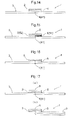
- the protection body 9 is not necessarily completely released from the base plate 3, and only needs to be released from the base plate 3 beyond the perforation 41. Thereafter, as shown in FIG.
- the user breaks the base plate 3 along the perforation 41 to remove the protection portion 9 and one part of the base plate 3 on which the sandwiching body 8 is not provided.
- a portion of the drug layer 2 is sandwiched in the sandwiching space 81 between the base plate 3 and the sandwiching body 8, while the other portion of the drug layer 2 is exposed from the base plate 3 and the sandwiching body 8 (see FIG. 13(c) ).
- the user moves the drug layer 2 toward the administration site while holding a portion of the base plate 3 and the sandwiching body 8 that is located in the vicinity of an end portion opposite to the drug layer 2.
- the user pulls down the lower eyelid using a finger of one hand to expose the conjunctiva, and moves the drug layer 2 toward the eye surface while holding the portion in the vicinity of the end portion of the base plate 3 and the sandwiching body 8 using fingers of the other hand.
- the user causes a portion of the drug layer 2 protruding from the base plate 3 to come into contact with the eye surface so that the drug layer 2 is completely released from the base plate 3, whereby the drug layer 2 is administered to the eye surface.
- the base plate 3 and the sandwiching body 8 function as a support body that delivers the drug layer 2 to the administration site during administration of the drug layer 2.
- different portions of the surface of the base plate 3 are formed of different materials so that the different portions have different sticking forces.
- the different portions may be caused to have different sticking forces by changing the surface condition (e.g., surface roughness etc.) of the base plate.
- the different portions may not necessarily need to have different sticking forces.
- the perforation 41 is formed as the fragile portion as an example.
- the fragile portion may be any configuration that has a lower flexural strength than that of the other portion of the base plate 3, including, for example, a portion having a cut penetrating halfway in the thickness direction, a groove portion, a portion having a smaller thickness than that of the other portion, or the like.
- the fragile portion is preferably provided in one surface of the base plate 3 that is opposite to another surface on which the drug layer 2 is provided, the present invention is not limited to this.
- the fragile portion may be provided on the surface of the base plate 3 on which the drug layer 2 is provided.
- the fragile portion may be provided on both surfaces of the base plate 3.
- the fragile portion may not necessarily need to be provided.
- a sign indicating a bending portion is preferably provided on the base plate so that the user can find the bending portion. Examples of the sign include, but are not particularly limited to, a dashed line, a solid line and the like. Note that both the fragile portion and the sign may be provided.
- a cover layer 6 may be provided on an upper surface of the drug layer 2.
- the material for the cover layer 6 may be, for example, but not limited to, biodegradable polymer, water-soluble polymer or the like as appropriate.
- the cover layer may have an ability to stick to the administration site in order to allow the drug layer 2 to be accurately administered to the administration site.
- the drug layer 2 is provided on one side of the bending portion 4 and the sticky layer 5 is provided on the other side, and the cover layer 6 is provided, extending over the upper surfaces of the drug layer 2 and the sticky layer 5.
- the bending portion 4 is a line of the perforation 41.
- the bending portion 4 may be a plurality of adjacent lines of perforations 41.
- the bending portion 4 is two adjacent lines of perforations 41a and 41b.
- the bending portion 4 may be three or more lines of perforations 41.
- the base plate 3 is bent at a portion in which the perforations 41a and 41b are formed.
- the drug layer 2 is released and exposed from the base plate 3, excluding a portion thereof which is formed in a region of the base plate 3 between the two perforations 41a and 41b.
- outer regions in the longitudinal direction of the drug layer 2 are released and exposed from the base plate 3 while a region in the vicinity of the middle portion in the longitudinal direction of the drug layer 2 is attached to the region of the base plate 3 between the perforations 41a and 41b.
- the bending portion 4 may be a plurality of adjacent lines of perforations 41.
- FIG. 19 shows an example of the third embodiment in which the bending portions 4a and 4b are each a plurality of adjacent lines of perforations 41.
- the bending portions 4a and 4b are each two adjacent lines of perforations 41a and 41b. Note that, even in any of the other embodiments, the bending portion 4 may be similarly a plurality of adjacent lines of perforations 41.
- the drug layer 2 sticks to the base plate 3 as an example.
- the drug layer 2 may be physically held on the base plate 3.
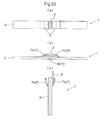
- two holding members 7 (7a, 7b) are provided in the vicinity of a middle portion of the base plate. As shown in FIGS. 20(a) and 20(b) , outer end portions (fixed ends) of the holding members 7a and 7b in the longitudinal direction of the base plate 3 are fixed to the base plate 3, while inner end portions (free ends) of the holding members 7a and 7b in the longitudinal direction of the base plate 3 are not fixed to the base plate 3.
- the drug layer 2 is held on the base plate 3 by being sandwiched between the holding members 7a and 7b and the base plate 3.
- the drug layer 2 is provided on the base plate 3.
- the two holding members 7a and 7b are provided as an example, there may be one or three or more holding members 7.
- the holding member 7 (7a, 7b) is not particularly limited, and is preferably formed of a flexible material, such as, for example, plastic, paper, film or the like.
- the holding member 7 (7a, 7b) is preferably formed of a transparent or translucent material to allow the user to see the drug layer 2 through the holding member 7. When the holding members 7a and 7b are bent, the drug layer 2 is inserted between the base plate 3 and the holding members 7a and 7b.
- the user bends the base plate 3 in a direction opposite to the surface on which the drug layer 2 is formed while holding portions in the vicinity of both end portions of the base plate 3 using fingers, one (7a) of the holding members 7a and 7b is bent, so that the drug layer 2 is no longer sandwiched between the holding member 7a and the base plate 3.
- FIG. 20(c) shows that only one end portion of the drug layer 2 is sandwiched between the base plate 3 and the holding member 7b, and the other end of the drug layer 2 (i.e., the portion that was sandwiched between the base plate 3 and the holding member 7a) protrudes from the base plate 3.
- the user can deliver the drug layer 2 to the administration site using the folded base plate 3 as a support body.
- the present invention is applicable to support bodies having a drug that is to be administered to the anterior segment of the eye, and methods for producing the support body.
Landscapes
- Health & Medical Sciences (AREA)
- Animal Behavior & Ethology (AREA)
- Veterinary Medicine (AREA)
- Engineering & Computer Science (AREA)
- Public Health (AREA)
- General Health & Medical Sciences (AREA)
- Life Sciences & Earth Sciences (AREA)
- Vascular Medicine (AREA)
- Heart & Thoracic Surgery (AREA)
- Biomedical Technology (AREA)
- Ophthalmology & Optometry (AREA)
- Epidemiology (AREA)
- Chemical & Material Sciences (AREA)
- Medicinal Chemistry (AREA)
- Pharmacology & Pharmacy (AREA)
- Bioinformatics & Cheminformatics (AREA)
- Dermatology (AREA)
- Manufacturing & Machinery (AREA)
- Media Introduction/Drainage Providing Device (AREA)
- Medicinal Preparation (AREA)
- Pharmaceuticals Containing Other Organic And Inorganic Compounds (AREA)
- Catching Or Destruction (AREA)
- Agricultural Chemicals And Associated Chemicals (AREA)
Abstract
Description
- The present invention relates to support bodies having a drug that is to be administered to the anterior segment of the eye, and methods for producing the drug support body.
- Eye drops are conventionally well known as ophthalmic drugs that are administered to the anterior segment of the eye. In eye drop administration, a liquid drug contained in an eye drop container is administered in drops. The amount of each drop may vary depending on pressure applied to the eye drop container, and may not be necessarily equal to the desired dose.
- On the other hand, as a means for administering a predetermined amount of a drug to the anterior segment of the eye, a technique of using a solid composition as an ophthalmic drug and inserting the solid composition is known. For such an ophthalmic drug, a drug component(s) that needs to be administered at one time is contained in a single solid composition, and therefore, a predetermined amount of the drug can be administered. However, the drug is held directly by the hand, and therefore, it is not easy to maintain the drug in sterile condition.
- As an ophthalmic drug that overcomes the above problem,
Patent Document 1 describes an applicator for administering a drug to a moist biological surface. Specifically, the applicator is a disposable applicator having an elongated strip shape at one end of which a drug containing a drug component in a soluble matrix is provided. The drug and the applicator are connected together via a separation portion formed of a soluble thin film (see the claims andfigure 1 ). In the applicator, the drug itself is allowed to come into contact with the biological surface as an administration site while the other end portion opposite to the drug itself of the applicator is held. As a result, the separation portion is dissolved, so that the drug itself is separated from the applicator, and the drug itself is administered. Thus, the use of the disposable applicator facilitates maintenance of sterile condition during drug administration. - Patent Document 1:
JP H4-11229 B2 - However, in the above applicator, the applicator, the separation portion and the drug itself are disposed along the longitudinal direction. Typically, the drug itself and the separation portion, which are formed of a soluble matrix or the like, have a low strength. Therefore, in the applicator having the above configuration, the separation portion or the drug itself is likely to be damaged, and therefore, it is difficult to produce and handle the applicator.
- The present invention has been made in view of the above background. It is an object of the present invention to provide a drug support body that can be used to appropriately administer a drug to the anterior segment of the eye while reducing the production cost.
- A drug support body according to the present invention includes a drug layer containing a drug component to be administered to an anterior segment of an eye, at a halfway portion in a longitudinal direction of a base plate, wherein the base plate includes a bending portion that allows the base plate to bend in a direction opposite to a surface of the base plate on which the drug layer is provided, and by bending the base plate at the bending portion, at least a portion of a surface facing the base plate of the drug layer is exposed from the base plate.
- With this configuration, the drug layer is provided on the base plate, and therefore, the drug layer, whose strength is typically low, is protected by the base plate. Therefore, the drug layer can be prevented from being damaged, and therefore, it is easier to produce and handle the drug layer. When the base plate is bent at the bending portion, the surface facing the base plate of the drug layer is exposed from the base plate. Therefore, the base plate thus bent can be used as the above applicator. Therefore, the drug can be administered while being maintained in sterile condition.
The bending portion of the base plate is located at a tip end portion of the base plate serving as an applicator on the drug layer side. The bending portion typically has a round and smooth shape, and therefore, the tip end portion of the applicator can have a smooth shape without particularly processing the base plate. Therefore, when the drug layer is administered, the anterior segment of the eye can be prevented from being damaged.
In other words, in the case of the applicator described inPatent Document 1, the tip of the applicator needs to be smoothed in order to prevent the biological surface as an administration site from being damaged, resulting in the additional cost of processing the tip portion. As described above, the bending portion typically has a round and smooth shape, and therefore, the tip end portion of the applicator can have a smooth shape without particularly processing the base plate. Therefore, the cost of processing the applicator can be reduced.
As a result, a drug support body can be provided that can be used to appropriately administer a drug to the anterior segment of the eye while the production cost is reduced. - In the above embodiment, a portion facing the base plate of the drug layer may be exposed from the base plate in various forms. For example, the drug layer may be formed to extend over both sides of a portion of the base plate in which the bending portion is formed, and when the base plate is bent at the bending portion, a portion of the drug layer on one side of the bending portion may be maintained facing the base plate while another portion of the drug layer on the other side of the bending portion may be exposed from the base plate and protrudes from the bending portion. Alternatively, the drug layer may be formed to extend over both sides of a portion of the base plate in which the bending portion is formed, and when the base plate is bent at the bending portion, a predetermined portion of the drug layer including a portion corresponding to the bending portion may be maintained facing the base plate while portions on both sides of the predetermined portion may be exposed from the base plate.
- A plurality of bending portions are preferably provided in the base plate, and the drug layer is preferably formed at a portion of the base plate in which one of the bending portions is formed.
- With this configuration, when the base plate is bent at the bending portions, the base plate can be put into a generally polygonal shape, whereby the strength of the base plate after being bent can be increased. Also, the position or orientation of the drug layer can be changed by changing the polygonal shape, and therefore, the drug layer can be put into a position or orientation that allows the drug layer to be easily administered.
- In the above configuration, of the portions of the drug layer sticking to the base plate, a portion that is released when the base plate is bent preferably has a sticking force smaller than that of the other portion.
- With this configuration, when the base plate is bent, a portion of the drug layer having a lower sticking force is reliably released from the base plate due to the difference in the sticking force of the base plate and the drug layer. Therefore, the drug can be more accurately administered.
- In the above configuration, a sticky layer is preferably provided between the drug layer and the base plate.
- The drug layer may have a somewhat large sticking force. However, some drug layers may not have a sufficient sticking force depending on conditions such as types of drug layers. In this case, by providing a sticky layer between the drug layer and the base plate, the drug layer can be reliably formed on the base plate.
- In the drug support body of the present invention, the present invention is not limited to the configuration in which the drug layer is provided on the base plate by causing the drug layer to stick to the base plate. For example, a holding member configured to hold the drug layer may be provided on the base plate, and the drug layer may be provided on the base plate by being sandwiched between the base plate and the holding member.
- In the above configuration, a cover layer configured to cover the drug layer is preferably formed on an upper surface of the drug layer.
- With this configuration, the drug layer can be reliably protected by the base plate and the cover layer, and therefore, it is easier to handle the drug layer.
- In the above configuration, a fragile portion having a flexural strength lower than that of the other portion of the base plate is preferably formed in the bending portion.
- With this configuration, when the base plate is bent, the base plate can be reliably bent at the fragile portion having a lower flexural strength than that of the other portion.
- In the above configuration, a sign indicating a portion to be bent is preferably formed at the bending portion.
- With this configuration, the user can visually recognize the bending portion, and therefore, can bend the base plate at the appropriate position.
- A method for producing the drug support body of the present invention includes a drug layer forming step of forming the drug layer along a longitudinal direction of an original material for the base plate, a bending portion forming step of forming the bending portion along the longitudinal direction of the original material for the base plate, and a cutting step of, after the drug layer forming step and the bending portion forming step, cutting the original material of the base plate along a direction perpendicular to the longitudinal direction at a predetermined interval.
- In a drug support body according to the present invention, a fragile portion having a strength lower than that of the other portion is formed at a halfway portion in a longitudinal direction of a base plate. The drug support body includes a drug layer containing a drug component to be administered to an anterior segment of an eye and formed on one surface of the base plate, extending across the fragile portion, a sandwiching body provided on the one surface of the base plate, extending from one end in the longitudinal direction of the drug layer, and configured so that the drug layer is sandwiched between the sandwiching body and the base plate, and a protection body extending from the other end in the longitudinal direction of the drug layer, over the upper surface of the drug layer and further at least a portion of an upper surface of the sandwiching body.
- With this configuration, the drug layer is provided on the base plate. The drug layer, whose strength is typically low, is provided on the base plate. The drug layer is sandwiched between the base plate and the sandwiching body, and the protection body is provided on the upper surface of the drug layer. Therefore, the drug layer is protected and prevented from being damaged, and therefore, it is easier to produce and handle the drug layer.
The drug layer extends across the fragile portion that is formed at the halfway portion in the longitudinal direction of the base plate. Therefore, after the drug layer is exposed from the protection body, if the base plate is broken or bent along the fragile portion, the drug layer is exposed from the base plate, and therefore, the base plate can be used as the above applicator. Therefore, the drug can be administered while being maintained in sterile condition.
As described above, a drug support body can be provided that can be used to appropriately administer a drug to the anterior segment of the eye while the production cost is reduced. - In the above configuration, the base plate and a region extending from the one end to the halfway portion of the sandwiching body are preferably attached together, the drug layer is preferably sandwiched between the base plate and the sandwiching body in a portion in which the base plate and the sandwiching body are not attached together, and the protection body is preferably attached to a region extending from the other end of the base plate to at least a halfway portion in a longitudinal direction of the sandwiching body.
- With this configuration, the drug layer can be reliably sandwiched in a portion in which the base plate and the sandwiching body are not attached together. Also, because the protection body is attached to a region extending from the other end of the base plate to at least a halfway portion in a longitudinal direction of the sandwiching body, the protection body is reliably located on the upper surface of the drug layer, whereby the drug layer can be reliably protected.
- In the above configuration, the sandwiching body preferably extends over a region between an end portion at the one end of the base plate and the fragile portion, and the protection body preferably extends from an end portion at the other end of the base plate to the halfway portion of the sandwiching body.
- With this configuration, the sandwiching body extends over a region between an end portion at the one end of the base plate and the fragile portion. Therefore, the sandwiching body is provided throughout a portion of the base plate that acts as an applicator. Therefore, the base plate can be reinforced by the sandwiching body. As a result, even when the base plate is formed of a material having an insufficient strength, the base plate can be reliably used as an applicator.
- In the above configuration, a non-attached portion to which the sandwiching body is not attached is preferably formed in a predetermined region extending from an end portion of the protection body on the sandwiching body side.
- With this configuration, when the drug layer is exposed from the protection body, the protection body can be released from the non-attached portion. As a result, it is easier to handle the drug support body when the drug is administered.
-
-
FIG. 1 is a top view showing an example drug support body according to a first embodiment of the present invention. -
FIG. 2 is a side view showing an example drug support body according to a first embodiment of the present invention. -
FIG. 3 is a bottom view showing an example drug support body according to a first embodiment of the present invention. -
FIG. 4 is a top view showing an example base plate. -
FIG. 5 is a diagram showing an example method of using a drug support body according to the present invention. -
FIG. 6 is a diagram showing an example method for producing a drug support body according to the present invention. -
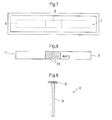
FIG. 7 is a diagram showing a drug support body that has been hermetically sealed and packaged. -
FIG. 8 is a top view showing an example base plate. -
FIG. 9 is a side view showing an example drug support body according to a second embodiment of the present invention. -
FIG. 10 is a side view showing an example drug support body according to a third embodiment of the present invention. -
FIG. 11 is a diagram showing an example drug support body according to a fourth embodiment of the present invention. -
FIG. 12 is a side view showing an example drug support body according to a fourth embodiment of the present invention. -
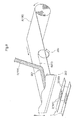
FIG. 13 is a diagram showing an example method of using a drug support body according to the present invention. -
FIG. 14 is a diagram showing a drug support body according to another embodiment. -
FIG. 15 is a diagram showing a drug support body according to another embodiment. -
FIG. 16 is a diagram showing a drug support body according to another embodiment. -
FIG. 17 is a diagram showing a drug support body according to another embodiment. -
FIG. 18 is a diagram showing a drug support body according to another embodiment. -
FIG. 19 is a diagram showing a drug support body according to another embodiment. -
FIG. 20 is a diagram showing a drug support body according to another embodiment. - Embodiments of a
drug support body 1 according to the present invention will be described hereinafter with reference to the accompanying drawings. Note that the present invention is not limited to the embodiments below, and various changes and modification can be made without departing the scope and spirit of the present invention. - A first embodiment of the
drug support body 1 of the present invention will be described with reference to the drawings.
As shown inFIGS. 1 to 3 , thedrug support body 1 includes abase plate 3, and adrug layer 2 provided on one surface of thebase plate 3. - The
base plate 3 has, for example, an elongated rectangular shape. Thebase plate 3 may be formed of any appropriate material, such as, but not particularly limited to, paper, plastic, aluminum foil or the like. Thebase plate 3 may also be formed of a stack of a plurality of layers of these materials. - As shown in
FIGS. 2 and 3 , a bendingportion 4 at which thebase plate 3 can be bent is provided at a middle portion in a longitudinal direction of thebase plate 3. In this embodiment, aperforation 41 is formed in the bending portion. Theperforation 41 is provided in one surface of thebase plate 3 that is opposite to another surface on which thedrug layer 2 is provided, extending along a direction perpendicular to the longitudinal direction of thebase plate 3. The holes of theperforation 41 do not completely pass through thebase plate 3, and penetrate halfway through the base plate in the thickness direction. Theperforation 41 thus formed in the bendingportion 4 causes the bendingportion 4 to have a lower flexural strength than that of the other portion of thebase plate 3. As a result, when thebase plate 3 is bent, thebase plate 3 can reliably bend at the bending portion 4 (seeFIG. 5(b) ). Theperforation 41 corresponds to a fragile portion of the present invention. - As shown in
FIGS. 1 and 2 , thedrug layer 2 is formed on one surface of thebase plate 3 that is opposite to another surface on which theperforation 41 is provided. Thedrug layer 2 is formed at a halfway portion in the longitudinal direction of thebase plate 3. Specifically, thebase plate 3 has regions that extend from both end portions toward the halfway portion in the longitudinal direction and in which thedrug layer 2 is not formed, and a region that is located at the halfway portion and in which thedrug layer 2 is formed. In this embodiment, thedrug layer 2 is formed at a substantially middle portion in the longitudinal direction of thebase plate 3, and theperforation 41 is located at a substantially middle portion in the longitudinal direction of thedrug layer 2. Thedrug layer 2 is formed, for example, of a solid composition containing a drug component. As the solid composition, for example, a water-soluble polymer or the like may be employed. The solid composition of thedrug layer 2 is dissolved after administration, so that the drug component is absorbed into the administration site. Thedrug layer 2 may include a plurality of layers, and the layers may have the same or different drug components. Thedrug layer 2 is administered to an anterior segment of the eye. - The
drug layer 2 sticks to thebase plate 3 by means of a sticking force of the solid composition. In this embodiment, the drug layer 2 (solid composition) is configured so that thedrug layer 2 has different levels of sticking force with respect to the base plate on opposite sides of the bendingportion 4. Specifically, for example, a surface of thebase plate 3 on which thedrug layer 2 is formed is formed of different materials so that one side of the bending portion has a higher releasability, resulting in a lower sticking force between thebase plate 3 and thedrug layer 2. In this embodiment, as shown inFIG. 4 , arelease film layer 31 having a higher releasability is formed in a predetermined region extending from the bendingportion 4 to one end portion of the base plate 3 (i.e., a region extending to a portion somewhat closer to that end portion of the base plate than is the end portion of the drug layer). Therefore, when the base plate is bent, a portion of the drug layer that is attached to the portion having a high releasability of the base plate is released and protrudes from the bending portion (seeFIGS. 5(b) and 5(c) ). Thus, at least a portion of a surface facing thebase plate 3 of thedrug layer 2 is exposed from thebase plate 3. Note that therelease film layer 31 may be formed throughout the region extending from the bendingportion 4 to the one end portion of thebase plate 3. - Next, a method of using the
drug support body 1 will be described. Although an example case where thedrug layer 2 is administered to the surface of the eye will be described, thedrug layer 2 may be administered to an anterior segment of the eye, such as, for example, cornea, palpebral conjunctiva, conjunctival sac or the like. As shown inFIGS. 5(a) and 5(b) , the user holds thebase plate 3 at portions in the vicinity of both end portions thereof using fingers, and bends thebase plate 3 in a direction opposite to the surface on which thedrug layer 2 is formed. In other words, thebase plate 3 is bent so that surfaces opposite to thedrug layer 2, of the portions in the vicinity of both end portions of thebase plate 3, face each other. As a result, as shown inFIG. 5(c) , thebase plate 3 is bent at a portion thereof corresponding to theperforation 41 formed in the bendingportion 4, and the surfaces opposite to thedrug layer 2 abut each other, i.e., thebase plate 3 is doubled up. In this case, as described above, a portion of thedrug layer 2 is exposed from thebase plate 3 and protrudes from the bending portion. - As shown in
FIG. 5(c) , the user holds, using fingers, the foldedbase plate 3 at a portion in the vicinity of an end portion thereof opposite to thedrug layer 2, i.e., the portions in the vicinity of both end portions of thebase plate 3 before being folded, and moves thedrug layer 2 toward the administration site. In this embodiment, as shown inFIG. 5(d) , the user pulls down the lower eyelid using a finger of one hand to expose the conjunctiva, and moves thedrug layer 2 toward the eye surface while holding thebase plate 3 at the portions in the vicinity of the end portion opposite to thedrug layer 2 using fingers of the other hand. The user causes a portion of thedrug layer 2 protruding from thebase plate 3 to come into contact with the eye surface so that thedrug layer 2 is completely released from thebase plate 3, whereby thedrug layer 2 is administered to the eye surface. As described above, the foldedbase plate 3 functions as a support body that delivers thedrug layer 2 to the administration site during administration of thedrug layer 2. With the above configuration, when thebase plate 3 functions as a support body, thebase plate 3 is doubled up, and the presence of the folded portion increases the strength of thebase plate 3. Therefore, when thebase plate 3 functions as a support body, thebase plate 3 is prevented from being accidentally deformed, whereby thedrug layer 2 can be accurately delivered to the administration site.
Note that, in the above embodiment, a separation portion (e.g., a perforation etc.) may be provided in thedrug layer 2 itself (e.g., a drug film etc.) at or close to a position corresponding to theperforation 41 of thebase plate 3. In this embodiment, when the user folds the base plate (seeFIG. 5(c) ), a portion of thedrug layer 2 is exposed from thebase plate 3 and protrudes from the bending portion, and the separation portion (e.g., a perforation etc.) is located at or close to the bending portion of thedrug layer 2. Thereafter, when the user causes thedrug layer 2 to come into contact with the administration site (e.g., the eye surface etc.) in order to administer thedrug layer 2 to the administration site (seeFIG. 5(d) ), thedrug layer 2 is separated at the separation portion, so that a portion of thedrug layer 2 protruding from the bending portion is administered to the administration site. On the other hand, the other portion of thedrug layer 2 is left on thebase plate 3. Thus, also in the embodiment in which the separation portion is provided in thedrug layer 2, thedrug layer 2 can be accurately administered to the administration site. - Next, an example method for producing the
drug support body 1 will be described.
As shown inFIG. 6 , anoriginal material 100 for thebase plate 3 is, for example, a roll of a long strip-shaped material. Theoriginal material 100 is supplied, sequentially from the leading end thereof, to a bendingportion formation unit 200. In the bendingportion formation unit 200, theperforation 41 is formed in one surface of theoriginal material 100 that is opposite to another surface on which thedrug layer 2 is to be formed. Theperforation 41 is continuously formed in a middle portion in a width direction of theoriginal material 100 along a longitudinal direction (a direction in which the original material is transported). The holes of theperforation 41 do not completely pass through theoriginal material 100, and penetrate halfway through theoriginal material 100 in the thickness direction. The bendingportion formation unit 200 includes a member that can continuously form holes of theperforation 41 in the case of forming theperforation 41 in the bendingportion 4, such as, for example, but not limited to, a needle member, a perforation cutter or the like. - The
original material 100 in which theperforation 41 has been formed is transported to a druglayer formation unit 201 that is provided downstream in the transport direction. In the druglayer formation unit 201, thedrug layer 2 is formed on one surface of theoriginal material 100 that is opposite to another surface in which theperforation 41 has been formed. Thedrug layer 2 is formed at a halfway portion in the width direction of the original material. As thedrug layer 2, for example, a long strip-shapeddrug film 101 including a solid composition containing a drug component is employed. Note that, as thedrug layer 2, a solid composition containing a drug component may be applied to theoriginal material 100 instead of thedrug film 101. As shown inFIG. 6 , as theoriginal material 100 is transported, thedrug film 101 is caused to stick to the halfway portion in the width direction of theoriginal material 100, so that thedrug layer 2 is continuously formed along the longitudinal direction (i.e., the transport direction) of theoriginal material 100. Alternatively, a solution in which a drug component is dissolved may be cast to theoriginal material 100 to form thedrug film 101 as thedrug layer 2. - The
original material 100 on which thedrug layer 2 has been formed is transported to acutting unit 202 that is provided downstream of the druglayer formation unit 201. In thecutting unit 202, theoriginal material 100 is cut along a direction perpendicular to the longitudinal direction at a predetermined interval. Thecutting unit 202 includes, for example, but not limited to, a cutter or the like that can cut theoriginal material 100. As a result, thedrug support body 1 whose longitudinal direction is the width direction of theoriginal material 100 is formed. - Thereafter, as shown in
FIG. 7 , thedrug support body 1 is individually hermetically sealed and packaged. Thedrug support body 1 in the hermetically sealed package is sterilized, for example, by irradiation with ultraviolet light, y rays, electron beams or the like. As a result, thedrug support body 1 is hermetically sealed and packaged in sterile condition. - A second embodiment of the
drug support body 1 of the present invention will be described with reference to the drawings.
In this embodiment, the sticking force of the drug layer 2 (solid composition) to thebase plate 3 varies between a predetermined region including the bendingportion 4 and the other region. Specifically, for example, as shown inFIG. 8 , in the longitudinal direction of thebase plate 3, the surface of thebase plate 3 on which thedrug layer 2 is formed is formed of different materials in different regions (i.e., the bendingportion 4 and predetermined regions on both sides of the bending portion 4 (at-and-near-bending-portion region), and regions closer to the end portions than is the at-and-near-bending-portion region) so that the regions closer to the end portions than is the at-and-near-bending-portion region have a higher releasability and therefore a smaller sticking force between thebase plate 3 and thedrug layer 2. Specifically, therelease film layer 31 having a higher releasability is formed in opposite predetermined regions (regions extending to portions somewhat closer to the end portions of the base plate than are the end portions of the drug layer) excluding a predetermined region in the vicinity of the bendingportion 4. Therefore, when thebase plate 3 is bent, a portion of thedrug layer 2 that is attached to the portion (the release film layer 31) having a higher releasability of the base plate is released. Therefore, as shown inFIG. 9 , the regions closer to both end portions of thedrug layer 2 are released and exposed from thebase plate 3 while only a portion corresponding to the at-and-near-bending-portion region of the drug layer 2 (i.e., a portion of thedrug layer 2 that is located in the vicinity of a middle portion in the longitudinal direction) is attached to thebase plate 3. Note that therelease film layer 31 may extend to the end portion of thebase plate 3. - As described above, in the
drug support body 1 of the second embodiment, thedrug layer 2 protrudes from thebase plate 3, excluding the portion in the vicinity of the middle portion in the longitudinal direction. Therefore, when thedrug layer 2 is administered, thebase plate 3 can be prevented from coming into contact with the administration site, i.e., the anterior segment of the eye. Moreover, after thedrug layer 2 comes into contact with the anterior segment of the eye, thedrug layer 2 can be easily released from thebase plate 3. Because thedrug layer 2 protruding substantially perpendicularly to thebase plate 3 comes into contact with the anterior segment of the eye, thedrug support body 1 is moved toward the anterior segment of the eye from the front. Therefore, for example, when thedrug layer 2 is administered to the anterior segment of an eye opposite to a hand holding thedrug support body 1, it is less difficult for the nose to interfere with thedrug support body 1 than when thedrug support body 1 is moved toward the anterior segment of the eye from a diagonal direction. As a result, thedrug layer 2 can be more easily administered. - A third embodiment of the
drug support body 1 of the present invention will be described with reference to the drawings.
In an example shown inFIG. 10 , bendingportions portion 4a is located at a substantially middle portion in the longitudinal direction of thedrug layer 2. The bendingportion 4b above which thedrug layer 2 is not formed is located at a point that is closer to one end portion of thebase plate 3 than is the middle portion in the longitudinal direction of thebase plate 3. The bendingportion 4a above which thedrug layer 2 is formed is formed in a region whose distance between the bendingportion 4b and the end portion of thebase plate 3 is longer. In this embodiment, as in the second embodiment, the surface of the base plate on which thedrug layer 2 is formed is formed of different materials in different regions (i.e., the bendingportion 4a and predetermined regions on both sides of the bendingportion 4a (at-and-near-bending-portion region), and regions closer to the end portions than is the at-and-near-bending-portion region) so that the regions closer to the end portions than is the at-and-near-bending-portion region have a higher releasability and therefore a smaller sticking force between thebase plate 3 and thedrug layer 2. As in the second embodiment, when the base plate is bent, the regions closer to both end portions of thedrug layer 2 are released and exposed from thebase plate 3 while only a portion corresponding to the at-and-near-bending-portion region of the drug layer 2 (i.e., a portion of thedrug layer 2 that is located in the vicinity of a middle portion in the longitudinal direction) is attached to the base plate 3 (seeFIG. 10(c) ). - As described above, in the
drug support body 1 of the third embodiment, thedrug layer 2 protrudes from thebase plate 3, excluding the portion in the vicinity of the middle portion in the longitudinal direction. Therefore, when thedrug layer 2 is administered, thebase plate 3 can be prevented from coming into contact with the administration site, i.e., the anterior segment of the eye. Moreover, after thedrug layer 2 comes into contact with the anterior segment of the eye, thedrug layer 2 can be easily released from thebase plate 3. As a result, thedrug layer 2 can be more easily administered. - Note that, as in the first embodiment, the surface of the base plate on which the
drug layer 2 is formed may be formed of different materials on opposite sides of the bendingportion 4a. In this case, as in the first embodiment, when the base plate is bent, a portion of thedrug layer 2 that is attached to the portion having a higher releasability of thebase plate 3 is released and protrudes from the bending portion. - Next, a method of using the
drug support body 1 will be described. As shown inFIG. 10(a) , thebase plate 3 is bent at the bendingportion 4b above which thedrug layer 2 is not formed. In this case, as shown inFIG. 10(b) , an end portion of thebase plate 3 on one side of the bendingportion 4b on which thedrug layer 2 and the bendingportion 4a are formed protrudes from an end portion of thebase plate 3 on the other side. As shown inFIG. 10(b) , portions in the vicinity of both end portions of thebase plate 3 are relatively moved in directions that allow both end portions of thebase plate 3 to move toward each other, whereby thebase plate 3 is bent at the bendingportion 4a in a direction opposite to the surface on which thedrug layer 2 is formed. As a result, as shown inFIG. 10(c) , thebase plate 3 is bent into a generally triangular shape, and thedrug layer 2 is located at a vertex of the triangle. Only the portion in the vicinity of the middle portion of thedrug layer 2 is attached to thebase plate 3 while both end portions thereof are released and exposed from thebase plate 3. The user holds, using fingers, thebase plate 3 at portions in the vicinity of both end portions of thebase plate 3 as they were before thebase plate 3 was folded, and administers thedrug layer 2 to the administration site. In this case, by relatively moving the end portions of thebase plate 3 to change the triangular shape, thedrug layer 2 can be easily put into a position or orientation that allows thedrug layer 2 to be easily administered to the administration site. The generally triangular shape of thebase plate 3 increases the strength of thebase plate 3. Therefore, when thebase plate 3 functions as a support body, thebase plate 3 can be prevented from being accidentally deformed, whereby thedrug layer 2 can be accurately delivered to the administration site. - A fourth embodiment of the
drug support body 1 of the present invention will be described with reference to the drawings.
As shown inFIGS. 11 and 12 , thisdrug support body 1 includes abase plate 3, adrug layer 2 that is provided on thebase plate 3, asandwiching body 8 that is provided so that a portion of thedrug layer 2 is sandwiched between the sandwichingbody 8 and thebase plate 3, and aprotection body 9 that protects thedrug layer 2 on thebase plate 3. - The
base plate 3 has, for example, an elongated rectangular shape. Thebase plate 3 may be formed of any appropriate material, such as, but not particularly limited to, paper, plastic, aluminum foil or the like. Thebase plate 3 may also be formed of a stack of a plurality of layers of these materials. A surface treatment or the like may be performed as required on thebase plate 3, taking into consideration, for example, the releasability of thedrug layer 2 from thebase plate 3 when the drug is administered. - The
protection body 9 has, for example, but not particularly limited to, an elongated rectangular shape. Theprotection body 9 is formed of, for example, but not particularly limited to, resin film, particularly preferably transparent film. The sandwichingbody 8 also has, for example, but not particularly limited to, an elongated rectangular shape. The sandwichingbody 8 may be formed of, for example, but not particularly limited to, aluminum foil.
Note that the materials for theprotection body 9 and thesandwiching body 8 are not limited to the above materials, and aluminum-deposited film, alumina-deposited transparent film, silica-deposited transparent film, paper, plastic, aluminum foil or the like may be employed as appropriate. - As shown in
FIGS. 11 and 12 , thebase plate 3 has a fragile portion at a halfway portion in the longitudinal direction. The fragile portion has a lower strength than that of the other portion so that the base plate can be bent or broken at the fragile portion. In this embodiment, aperforation 41 is formed in the fragile portion. In this embodiment, theperforation 41 passes through thebase plate 3. The fragile portion is thus configured by forming theperforation 41 so that the strength is weaker than that of the other portion of thebase plate 3. As a result, thebase plate 3 can be reliably bent or broken at the fragile portion. Note that theperforation 41 may not pass through thebase plate 3 in the thickness direction, and may penetrate halfway through thebase plate 3 in the thickness direction. The fragile portion is not limited to theperforation 41, and may be, for example, a portion having a cut penetrating halfway in the thickness direction, a portion having a smaller thickness than that of the other portion, a portion having a crease previously formed on the base plate and therefore a lower strength than that of the other portion, or the like, instead of the perforation. - As shown in
FIG. 12 , thedrug layer 2 is formed on one surface of thebase plate 3. Thedrug layer 2 extends across the fragile portion (the halfway portion in the longitudinal direction of thedrug layer 2 is located above the fragile portion). In other words, in the longitudinal direction of thebase plate 3, thebase plate 3 has regions that extend from both end portions toward the halfway portion and in which thedrug layer 2 is not formed, and a region that includes theperforation 41 of the halfway portion and in which thedrug layer 2 is formed. Thedrug layer 2 is formed of, for example, a solid composition containing a drug component. As the solid composition, for example, a water-soluble polymer or the like may be employed. The solid composition of thedrug layer 2 is dissolved after administration, so that the drug component is absorbed into the administration site. Thedrug layer 2 may include a plurality of layers, and the layers may have the same or different drug components. Thedrug layer 2 is administered to an anterior segment of the eye. - In this embodiment, the sandwiching
body 8 is provided on the surface of thebase plate 3 on which thedrug layer 2 is provided, extending from one end in the longitudinal direction of the surface to the portion in which theperforation 41 is formed. As a result, a portion of thedrug layer 2 is sandwiched between the sandwichingbody 8 and thebase plate 3. In this embodiment, a heat seal layer is provided on the surface of thebase plate 3 on which thedrug layer 2 is provided. The base plate and thesandwiching body 8 are integrated together by heat sealing. Here, a portion of thesandwiching body 8 that is in the vicinity of the end portion closer to theperforation 41 is not attached to thebase plate 3 by heat sealing, and forms a sandwichingspace 81 in which thedrug layer 2 is sandwiched (seeFIGS. 11 and 12 ). Although, in this embodiment, theperforation 41 and the end portion of thesandwiching body 8 coincide in position, theperforation 41 and the end portion of thesandwiching body 8 do not necessarily coincide in position. Alternatively, for example, the end portion of thesandwiching body 8 may be located slightly short of theperforation 41 or slightly beyond theperforation 41. - In this embodiment, the
protection body 9 is provided on the surface of thebase plate 3 on which thedrug layer 2 is provided, extending from the other end (the end opposite to the side on which thesandwiching body 8 is provided) to a halfway portion in the longitudinal direction of thesandwiching body 8. As a result, theprotection body 9 is provided over thedrug layer 2. As described above, the heat seal layer is provided on thebase plate 3 to attach theprotection body 9 and thebase plate 3 together by heat sealing. The sandwichingbody 8 and theprotection body 9 are also attached together by heat sealing. - In this embodiment, the
protection body 9 has anon-attached portion 91 to which thesandwiching body 8 is not attached, at an end portion thereof on thesandwiching body 8 side. Specifically, a part of the end portion of theprotection body 9 on thesandwiching body 8 side is folded in two parts, and the two parts are fused together by melting, whereby the resulting part has a higher strength than that of the other portion and is prevented from being attached to thesandwiching body 8. Note that thenon-attached portion 91 is not limited to the above form, and alternatively, for example, the end portion of theprotection body 9 on thesandwiching body 8 side may have any form that prevents the end portion from being attached to thesandwiching body 8 without folding the end portion in two parts and fusing the two parts by melting. Thenon-attached portion 91 acts as a tab to remove theprotection body 9 during use of thedrug support body 1.
Note that thenon-attached portion 91 may not be necessarily provided. - Next, a method of using the
drug support body 1 will be described with reference toFIG. 13 . Although an example case where thedrug layer 2 is administered to the surface of the eye will be described, thedrug layer 2 may be administered to an anterior segment of the eye, such as, for example, cornea, palpebral conjunctiva, conjunctival sac or the like. As shown inFIG. 13(a) , the user removes theprotection body 9 from the sandwichingbody 8 by holding the tab (the non-attached portion 91) formed on theprotection portion 9. In this case, theprotection body 9 is not necessarily completely released from thebase plate 3, and only needs to be released from thebase plate 3 beyond theperforation 41. Thereafter, as shown inFIG. 13(b) , the user breaks thebase plate 3 along theperforation 41 to remove theprotection portion 9 and one part of thebase plate 3 on which thesandwiching body 8 is not provided. As a result, a portion of thedrug layer 2 is sandwiched in the sandwichingspace 81 between thebase plate 3 and thesandwiching body 8, while the other portion of thedrug layer 2 is exposed from thebase plate 3 and the sandwiching body 8 (seeFIG. 13(c) ). - As shown in
FIG. 13(c) , the user moves thedrug layer 2 toward the administration site while holding a portion of thebase plate 3 and thesandwiching body 8 that is located in the vicinity of an end portion opposite to thedrug layer 2. In this embodiment, as shown inFIG. 13(d) , the user pulls down the lower eyelid using a finger of one hand to expose the conjunctiva, and moves thedrug layer 2 toward the eye surface while holding the portion in the vicinity of the end portion of thebase plate 3 and thesandwiching body 8 using fingers of the other hand. The user causes a portion of thedrug layer 2 protruding from thebase plate 3 to come into contact with the eye surface so that thedrug layer 2 is completely released from thebase plate 3, whereby thedrug layer 2 is administered to the eye surface. As described above, thebase plate 3 and thesandwiching body 8 function as a support body that delivers thedrug layer 2 to the administration site during administration of thedrug layer 2. -
- (1) In the above embodiments, the
drug layer 2 is provided directly on thebase plate 3 as an example. Alternatively, asticky layer 5 may be provided between thebase plate 3 and thedrug layer 2.
In this case, as shown inFIG. 14 , a singlesticky layer 5 may be provided throughout thedrug layer 2.
Alternatively, as shown inFIG. 15 , differentsticky layers 5 may be provided on opposite sides of the bending portion 4 (the perforation 41), i.e., a highlysticky layer 51 having a high sticking force and a lesssticky layer 52 having a smaller sticking force than that of the highlysticky layer 51, may be formed. Note that when this embodiment is applied to an embodiment similar to the second or third embodiment, the highlysticky layer 51 may be formed on a portion in the vicinity of the bending portion 4 (4a), and the lesssticky layer 52 may be formed on opposite sides of that portion.
As shown inFIG. 16 , thesticky layer 5 may be provided on only one side of the bending portion 4 (the perforation 41). Note that when this embodiment is applied to an embodiment similar to the second or third embodiment, thesticky layer 5 may be provided on only a portion in the vicinity of the bending portion 4 (4a). - (2) In the above embodiments, different portions of the surface of the
base plate 3 are formed of different materials so that the different portions have different sticking forces. Alternatively, instead of providing different materials, the different portions may be caused to have different sticking forces by changing the surface condition (e.g., surface roughness etc.) of the base plate. The different portions may not necessarily need to have different sticking forces. - (3) In the above embodiments, the
perforation 41 is formed as the fragile portion as an example. The present invention is not limited to this. Alternatively, the fragile portion may be any configuration that has a lower flexural strength than that of the other portion of thebase plate 3, including, for example, a portion having a cut penetrating halfway in the thickness direction, a groove portion, a portion having a smaller thickness than that of the other portion, or the like. Although, as described above, the fragile portion is preferably provided in one surface of thebase plate 3 that is opposite to another surface on which thedrug layer 2 is provided, the present invention is not limited to this. The fragile portion may be provided on the surface of thebase plate 3 on which thedrug layer 2 is provided. Alternatively, the fragile portion may be provided on both surfaces of thebase plate 3. - (4) The fragile portion may not necessarily need to be provided. Note that when the fragile portion is not provided, a sign indicating a bending portion is preferably provided on the base plate so that the user can find the bending portion. Examples of the sign include, but are not particularly limited to, a dashed line, a solid line and the like. Note that both the fragile portion and the sign may be provided.
- (5) As shown in
FIG. 17 , acover layer 6 may be provided on an upper surface of thedrug layer 2. The material for thecover layer 6 may be, for example, but not limited to, biodegradable polymer, water-soluble polymer or the like as appropriate. Note that the cover layer may have an ability to stick to the administration site in order to allow thedrug layer 2 to be accurately administered to the administration site. In the example ofFIG. 17 , thedrug layer 2 is provided on one side of the bendingportion 4 and thesticky layer 5 is provided on the other side, and thecover layer 6 is provided, extending over the upper surfaces of thedrug layer 2 and thesticky layer 5. - (6) In the above embodiments, the bending
portion 4 is a line of theperforation 41. Alternatively, the bendingportion 4 may be a plurality of adjacent lines ofperforations 41. For example, in the case of the second embodiment, as shown inFIG. 18(a) , the bendingportion 4 is two adjacent lines ofperforations portion 4 may be three or more lines ofperforations 41. In this embodiment, as in the above embodiments, when the user bends thebase plate 3 in a direction opposite to the surface on which thedrug layer 2 is formed while holding portions in the vicinity of both end portions of thebase plate 3 using fingers, as shown inFIG. 18(b) thebase plate 3 is bent at a portion in which theperforations FIG. 18(c) , thedrug layer 2 is released and exposed from thebase plate 3, excluding a portion thereof which is formed in a region of thebase plate 3 between the twoperforations drug layer 2 are released and exposed from thebase plate 3 while a region in the vicinity of the middle portion in the longitudinal direction of thedrug layer 2 is attached to the region of thebase plate 3 between theperforations - Even in the other embodiments, the bending
portion 4 may be a plurality of adjacent lines ofperforations 41.FIG. 19 shows an example of the third embodiment in which thebending portions perforations 41. In this embodiment, the bendingportions perforations portion 4 may be similarly a plurality of adjacent lines ofperforations 41. - (7) In the above embodiments, when the
drug layer 2 is formed on thebase plate 3, thedrug layer 2 sticks to thebase plate 3 as an example. The present invention is not limited to this. For example, thedrug layer 2 may be physically held on thebase plate 3. In this embodiment, two holding members 7 (7a, 7b) are provided in the vicinity of a middle portion of the base plate. As shown inFIGS. 20(a) and 20(b) , outer end portions (fixed ends) of the holdingmembers base plate 3 are fixed to thebase plate 3, while inner end portions (free ends) of the holdingmembers base plate 3 are not fixed to thebase plate 3. Thedrug layer 2 is held on thebase plate 3 by being sandwiched between the holdingmembers base plate 3. Thus, thedrug layer 2 is provided on thebase plate 3. Although, in the above example, the two holdingmembers more holding members 7. - The holding member 7 (7a, 7b) is not particularly limited, and is preferably formed of a flexible material, such as, for example, plastic, paper, film or the like. The holding member 7 (7a, 7b) is preferably formed of a transparent or translucent material to allow the user to see the
drug layer 2 through the holdingmember 7. When the holdingmembers drug layer 2 is inserted between thebase plate 3 and the holdingmembers - When, as in the above embodiments, the user bends the
base plate 3 in a direction opposite to the surface on which thedrug layer 2 is formed while holding portions in the vicinity of both end portions of thebase plate 3 using fingers, one (7a) of the holdingmembers drug layer 2 is no longer sandwiched between the holdingmember 7a and thebase plate 3. As a result, as shown inFIG. 20(c) , only one end portion of thedrug layer 2 is sandwiched between thebase plate 3 and the holdingmember 7b, and the other end of the drug layer 2 (i.e., the portion that was sandwiched between thebase plate 3 and the holdingmember 7a) protrudes from thebase plate 3. Thus, a portion of thedrug layer 2 is exposed from thebase plate 3. As in the above embodiments, the user can deliver thedrug layer 2 to the administration site using the foldedbase plate 3 as a support body. - The present invention is applicable to support bodies having a drug that is to be administered to the anterior segment of the eye, and methods for producing the support body.
-
1 DRUG SUPPORT BODY 2 DRUG LAYER 3 BASE PLATE 31 RELEASE FILM LAYER 4 BENDING PORTION (FRAGILE PORTION) 41 PERFORATION OR HOLES OF PERFORATION 5 STICKY LAYER 51 HIGHLY STICKY LAYER 52 LESS STICKY LAYER 6 COVER LAYER 7 HOLDING MEMBER 8 SANDWICHING BODY 81 SANDWICHING SPACE 9 PROTECTION BODY 91 NON-ATTACHED PORTION 100 ORIGINAL MATERIAL 101 DRUG FILM 200 BENDING PORTION FORMATION PORTION 201 DRUG LAYER FORMATION PORTION 202 CUTTING UNIT
Claims (15)
- A drug support body comprising :a drug layer containing a drug component to be administered to an anterior segment of an eye, at a halfway portion in a longitudinal direction of a base plate,wherein the base plate includes a bending portion that allows the base plate to bend in a direction opposite to a surface of the base plate on which the drug layer is provided, and by bending the base plate at the bending portion, at least a portion of a surface facing the base plate of the drug layer is exposed from the base plate.
- The drug support body according to claim 1,
wherein the drug layer is formed to extend over both sides of a portion of the base plate in which the bending portion is formed, and when the base plate is bent at the bending portion, a portion of the drug layer on one side of the bending portion is maintained facing the base plate while another portion of the drug layer on the other side of the bending portion is exposed from the base plate and protrudes from the bending portion. - The drug support body according to claim 1,
wherein the drug layer is formed to extend over both sides of a portion of the base plate in which the bending portion is formed, and when the base plate is bent at the bending portion, a predetermined portion of the drug layer including a portion corresponding to the bending portion is maintained facing the base plate while portions on both sides of the predetermined portion are exposed from the base plate. - The drug support body according to any one of claims 1 to 3,
wherein a plurality of bending portions are provided in the base plate, and the drug layer is formed at a portion of the base plate in which one of the bending portions is formed. - The drug support body according to any one of claims 1 to 4,
wherein, of the portions of the drug layer sticking to the base plate, a portion that is released when the base plate is bent has a sticking force smaller than that of the other portion. - The drug support body according to any one of claims 1 to 5,
wherein a sticky layer is provided between the drug layer and the base plate. - The drug support body according to any one of claims 1 to 6,
wherein a holding member configured to hold the drug layer is provided on the base plate, and the drug layer is provided on the base plate by being sandwiched between the base plate and the holding member. - The drug support body according to any one of claims 1 to 7,
wherein a cover layer configured to cover the drug layer is formed on an upper surface of the drug layer. - The drug support body according to any one of claims 1 to 8,
wherein a fragile portion having a flexural strength lower than that of the other portion of the base plate is formed in the bending portion. - The drug support body according to any one of claims 1 to 9,
wherein a sign indicating a portion to be bent is formed at the bending portion. - A method for producing the drug support body according to any one of claims 1 to 10, comprising:a drug layer forming step of forming the drug layer along a longitudinal direction of an original material for the base plate;a bending portion forming step of forming the bending portion along the longitudinal direction of the original material for the base plate; anda cutting step of, after the drug layer forming step and the bending portion forming step, cutting the original material of the base plate along a direction perpendicular to the longitudinal direction at a predetermined interval.
- A drug support body comprising :wherein a fragile portion having a strength lower than that of the other portion is formed at a halfway portion in a longitudinal direction of a base plate, anda drug layer containing a drug component to be administered to an anterior segment of an eye and formed on one surface of the base plate, extending across the fragile portion, anda sandwiching body provided on the one surface of the base plate, extending from one end in the longitudinal direction of the drug layer, and configured so that the drug layer is sandwiched between the sandwiching body and the base plate, anda protection body extending from the other end in the longitudinal direction of the drug layer, over the upper surface of the drug layer and further at least a portion of an upper surface of the sandwiching body.
- The drug support body according to claim 12,
wherein the base plate and a region extending from the one end to the halfway portion of the sandwiching body are attached together, the drug layer is sandwiched between the base plate and the sandwiching body in a portion in which the base plate and the sandwiching body are not attached together, and the protection body is attached to a region extending from the other end of the base plate to at least a halfway portion in a longitudinal direction of the sandwiching body. - The drug support body according to claim 12 or 13,
wherein the sandwiching body extends over a region between an end portion at the one end of the base plate and the fragile portion, and the protection body extends from an end portion at the other end of the base plate to the halfway portion of the sandwiching body. - The drug support body according to any one of claims 12 to 14,
wherein a non-attached portion to which the sandwiching body is not attached is formed in a predetermined region extending from an end portion of the protection body on the sandwiching body side.
Applications Claiming Priority (2)
| Application Number | Priority Date | Filing Date | Title |
|---|---|---|---|
| JP2010171027 | 2010-07-29 | ||
| PCT/JP2011/067291 WO2012014986A1 (en) | 2010-07-29 | 2011-07-28 | Drug support body, and method for producing same |
Publications (2)
| Publication Number | Publication Date |
|---|---|
| EP2599517A1 true EP2599517A1 (en) | 2013-06-05 |
| EP2599517A4 EP2599517A4 (en) | 2015-12-30 |
Family
ID=45530186
Family Applications (1)
| Application Number | Title | Priority Date | Filing Date |
|---|---|---|---|
| EP11812575.6A Withdrawn EP2599517A4 (en) | 2010-07-29 | 2011-07-28 | MEDIUM SUPPORT BODY, AND METHOD FOR PRODUCING THE SAME |
Country Status (16)
| Country | Link |
|---|---|
| US (1) | US20130226111A1 (en) |
| EP (1) | EP2599517A4 (en) |
| JP (1) | JP5900875B2 (en) |
| KR (1) | KR20130046437A (en) |
| CN (1) | CN103189097B (en) |
| AU (1) | AU2011283586B2 (en) |
| BR (1) | BR112013002218A2 (en) |
| CA (1) | CA2807065A1 (en) |
| EA (2) | EA023551B1 (en) |
| MX (1) | MX2013001116A (en) |
| MY (1) | MY158722A (en) |
| NZ (1) | NZ606843A (en) |
| PH (1) | PH12013500193A1 (en) |
| SG (1) | SG187220A1 (en) |
| TW (1) | TW201219076A (en) |
| WO (1) | WO2012014986A1 (en) |
Families Citing this family (6)
| Publication number | Priority date | Publication date | Assignee | Title |
|---|---|---|---|---|
| WO2014119587A1 (en) * | 2013-01-29 | 2014-08-07 | 参天製薬株式会社 | Drug-bearing supporting medium provided with dissolution separation layer |
| JP2017043607A (en) * | 2015-08-24 | 2017-03-02 | 参天製薬株式会社 | Ophthalmologic film formulation |
| CN107103354B (en) * | 2017-06-21 | 2023-09-15 | 珠海市飞盛条码标识技术有限公司 | Anti-edge-warping fragile label and preparation method thereof |
| KR20190029333A (en) | 2017-09-12 | 2019-03-20 | 바이허브 주식회사 | Drug Support Body For Removal Of Oral Odor |
| JP2019108299A (en) * | 2017-12-19 | 2019-07-04 | 大協薬品工業株式会社 | Plaster formulation and method for producing the same |
| CN116115423B (en) * | 2023-04-04 | 2023-06-30 | 健诺维(成都)生物科技有限公司 | Ocular surface prosthetic devices and supporting component thereof |
Family Cites Families (31)
| Publication number | Priority date | Publication date | Assignee | Title |
|---|---|---|---|---|
| DE2116989C3 (en) * | 1971-04-07 | 1978-10-05 | Heinrich Hermann Gmbh + Co, 7000 Stuttgart | Tape, coated on both sides with self-adhesive adhesive, divided into sections |
| US4140409A (en) * | 1977-09-02 | 1979-02-20 | Baxter Travenol Laboratories, Inc. | Disposable liquid applicator |
| US4360020A (en) * | 1980-05-15 | 1982-11-23 | Baxter Travenol Laboratories, Inc. | Disposable swab |
| NZ200429A (en) * | 1981-04-30 | 1984-10-19 | Smith & Nephew Ass | Applicator for placing pharmaceutically active agent in contact with moist surface,e.g.,eye |
| DE3344335A1 (en) * | 1983-12-08 | 1985-06-13 | Lohmann Gmbh & Co Kg, 5450 Neuwied | LAMINATE SECTIONS WITH COVER AND REMOVAL AID THEREFOR |
| GB8721659D0 (en) * | 1987-09-15 | 1987-10-21 | Smith & Nephew Ass | Adhesive coated dressings & applicators |
| US4900552A (en) * | 1988-03-30 | 1990-02-13 | Watson Laboratories, Inc. | Mucoadhesive buccal dosage forms |
| JPH0418622U (en) * | 1990-06-01 | 1992-02-17 | ||
| AU676430B2 (en) * | 1994-03-07 | 1997-03-06 | Theratech, Inc. | Drug-containing adhesive composite transdermal delivery device |
| AU735387B2 (en) * | 1997-01-07 | 2001-07-05 | Teijin Limited | Isosorbide dinitrate-containing patch |
| JP4267926B2 (en) * | 2001-04-24 | 2009-05-27 | リンテック株式会社 | Orally administered drug and oral drug holder |
| US20020187181A1 (en) * | 2001-05-14 | 2002-12-12 | 3M Innovative Properties Company | System for delivering cosmetics and pharmaceuticals |
| DE10133870A1 (en) * | 2001-07-12 | 2003-02-06 | Chris P Lohmann | Ophthalmic agent, use of EGF for the treatment of dry eye syndrome and insert for the administration of EGF to the eye |
| TW544320B (en) * | 2002-02-08 | 2003-08-01 | Jung-Shin Lin | Medicine coating device with antibacterial dry intermediate section for coating and capable of instantaneously absorbing plural aseptic medical solutions |
| JP4454019B2 (en) * | 2002-07-15 | 2010-04-21 | アルコン,インコーポレイテッド | Bioerodible film for ophthalmic drug delivery |
| US20050047846A1 (en) * | 2003-08-28 | 2005-03-03 | Closure Medical Corporation | Single-use applicators for adhesive material, packaging systems, methods of use and methods of manufacture |
| FR2867362B1 (en) * | 2004-03-15 | 2007-09-21 | Oreal | ADHESIVE APPLICATION ARTICLE |
| JP2005289867A (en) * | 2004-03-31 | 2005-10-20 | Lintec Corp | Agent for peroral administration |
| JP4252497B2 (en) * | 2004-06-07 | 2009-04-08 | 日東電工株式会社 | Local anesthetic preparation for upper gastrointestinal endoscopy pretreatment |
| JP2006116071A (en) * | 2004-10-21 | 2006-05-11 | Qualitas:Kk | Ophthalmic drug delivery device |
| JP4769575B2 (en) * | 2005-12-28 | 2011-09-07 | 帝國製薬株式会社 | Patch and method for producing the same |
| CN101426474A (en) * | 2006-04-26 | 2009-05-06 | 皇家飞利浦电子股份有限公司 | Device for the controlled release of a substance and method of releasing a substance |
| US20090275925A1 (en) * | 2006-06-02 | 2009-11-05 | Koninklijke Philips Electronics N.V. | Device for the controlled release of a substance |
| JP5005277B2 (en) * | 2006-07-13 | 2012-08-22 | 日東電工株式会社 | Patches and patch preparations |
| JP4855890B2 (en) * | 2006-10-19 | 2012-01-18 | リバテープ製薬株式会社 | Medical dressing material and method for producing the same |
| US20080141597A1 (en) * | 2006-12-18 | 2008-06-19 | O'rourke Barbara Klimowicz | Flashing for integrating windows with weather resistant barrier |
| EP2170727B1 (en) * | 2007-07-03 | 2012-08-22 | Amcol International Corporation | Single dose dispensing package |
| CA2704929C (en) * | 2007-08-07 | 2018-05-15 | Pamela Palmer | Compositions and methods for procedural sedation and analgesia using oral transmucosal dosage forms |
| US8020700B2 (en) * | 2007-12-05 | 2011-09-20 | Ventus Medical, Inc. | Packaging and dispensing nasal devices |
| JP3150855U (en) * | 2009-03-16 | 2009-06-04 | 和代 小川 | Shape retention adhesive |
| US8211450B2 (en) * | 2010-05-05 | 2012-07-03 | Senju Usa, Inc. | Ophthalmic composition |
-
2011
- 2011-07-28 MY MYPI2013000288A patent/MY158722A/en unknown
- 2011-07-28 EA EA201390181A patent/EA023551B1/en not_active IP Right Cessation
- 2011-07-28 MX MX2013001116A patent/MX2013001116A/en not_active Application Discontinuation
- 2011-07-28 TW TW100126785A patent/TW201219076A/en unknown
- 2011-07-28 BR BR112013002218A patent/BR112013002218A2/en not_active IP Right Cessation
- 2011-07-28 CA CA2807065A patent/CA2807065A1/en not_active Abandoned
- 2011-07-28 EP EP11812575.6A patent/EP2599517A4/en not_active Withdrawn
- 2011-07-28 PH PH1/2013/500193A patent/PH12013500193A1/en unknown
- 2011-07-28 KR KR1020137004856A patent/KR20130046437A/en not_active Withdrawn
- 2011-07-28 US US13/812,676 patent/US20130226111A1/en not_active Abandoned
- 2011-07-28 JP JP2011165740A patent/JP5900875B2/en not_active Expired - Fee Related
- 2011-07-28 NZ NZ606843A patent/NZ606843A/en not_active IP Right Cessation
- 2011-07-28 CN CN201180046940.9A patent/CN103189097B/en not_active Expired - Fee Related
- 2011-07-28 WO PCT/JP2011/067291 patent/WO2012014986A1/en not_active Ceased
- 2011-07-28 EA EA201500501A patent/EA201500501A1/en unknown
- 2011-07-28 AU AU2011283586A patent/AU2011283586B2/en not_active Ceased
- 2011-07-28 SG SG2013006481A patent/SG187220A1/en unknown
Also Published As
| Publication number | Publication date |
|---|---|
| MX2013001116A (en) | 2013-06-05 |
| EA201390181A1 (en) | 2013-06-28 |
| AU2011283586B2 (en) | 2014-07-31 |
| JP2012045379A (en) | 2012-03-08 |
| CA2807065A1 (en) | 2012-02-02 |
| EP2599517A4 (en) | 2015-12-30 |
| NZ606843A (en) | 2014-06-27 |
| TW201219076A (en) | 2012-05-16 |
| HK1182656A1 (en) | 2013-12-06 |
| US20130226111A1 (en) | 2013-08-29 |
| CN103189097A (en) | 2013-07-03 |
| JP5900875B2 (en) | 2016-04-06 |
| AU2011283586A1 (en) | 2013-03-07 |
| MY158722A (en) | 2016-11-15 |
| PH12013500193A1 (en) | 2013-03-11 |
| EA201500501A1 (en) | 2015-12-30 |
| KR20130046437A (en) | 2013-05-07 |
| SG187220A1 (en) | 2013-02-28 |
| BR112013002218A2 (en) | 2016-05-24 |
| CN103189097B (en) | 2016-01-06 |
| EA023551B1 (en) | 2016-06-30 |
| WO2012014986A1 (en) | 2012-02-02 |
Similar Documents
| Publication | Publication Date | Title |
|---|---|---|
| AU2011283586B2 (en) | Drug support body, and method for producing same | |
| KR102358550B1 (en) | Packaged microneedle sheet and method for producing same | |
| ES2899952T3 (en) | Easy-open peel-off bag | |
| CN105026283A (en) | Tear-open pouch for fragile thin materials | |
| SK10222000A3 (en) | Primary packaging unit for film-like or oblate-like administered shapes | |
| KR20160033123A (en) | Support for a unit dose drug | |
| CA2712920C (en) | Label for placing on a syringe body, and syringe body | |
| EP1594761B1 (en) | Primary packaging used as an applicator | |
| HK1180986A (en) | Drug support body, and method for producing same | |
| JP6278672B2 (en) | Package for PTP sheet | |
| AU2013292245B2 (en) | Pack for individual active-substance-containing films, and method for producing said pack | |
| US10899519B2 (en) | Support for a product packaged in unit doses, and method for the production thereof | |
| TW201517919A (en) | Drug support body with soluble separation layer | |
| EP1688123B1 (en) | Packaging bag for pasting medicine | |
| HK1182656B (en) | Drug support body, and method for producing same | |
| ES2727074T3 (en) | Tape set containing information cards and blisters and method for assembly | |
| EP2942077B1 (en) | Mounting card | |
| JP4961499B1 (en) | Package to store a single dose of medicine taken on a specific day | |
| JP5174884B2 (en) | Drug package, blade for manufacturing drug package, device for manufacturing drug package | |
| KR101364776B1 (en) | Medicine | |
| US20120118782A1 (en) | Blister package stiffening | |
| JP2013100135A (en) | Medicine packet, blade for manufacturing medicine packet, and medicine packet manufacturing apparatus | |
| KR101364775B1 (en) | Medicine | |
| KR20160113432A (en) | Perforation forming cutter |
Legal Events
| Date | Code | Title | Description |
|---|---|---|---|
| PUAI | Public reference made under article 153(3) epc to a published international application that has entered the european phase |
Free format text: ORIGINAL CODE: 0009012 |
|
| 17P | Request for examination filed |
Effective date: 20130206 |
|
| AK | Designated contracting states |
Kind code of ref document: A1 Designated state(s): AL AT BE BG CH CY CZ DE DK EE ES FI FR GB GR HR HU IE IS IT LI LT LU LV MC MK MT NL NO PL PT RO RS SE SI SK SM TR |
|
| REG | Reference to a national code |
Ref country code: HK Ref legal event code: DE Ref document number: 1180986 Country of ref document: HK |
|
| DAX | Request for extension of the european patent (deleted) | ||
| RA4 | Supplementary search report drawn up and despatched (corrected) |
Effective date: 20151127 |
|
| RIC1 | Information provided on ipc code assigned before grant |
Ipc: A61M 35/00 20060101AFI20151123BHEP Ipc: A61K 9/00 20060101ALI20151123BHEP Ipc: A61F 9/00 20060101ALI20151123BHEP |
|
| RAP1 | Party data changed (applicant data changed or rights of an application transferred) |
Owner name: TSUKIOKA FILM PHARMA CO., LTD. Owner name: SANTEN PHARMACEUTICAL CO., LTD. |
|
| RIN1 | Information on inventor provided before grant (corrected) |
Inventor name: MIYOSHI, NAOHITO Inventor name: HORIBE, YOSHIHIDE Inventor name: TASAKA, FUMITAKA |
|
| GRAP | Despatch of communication of intention to grant a patent |
Free format text: ORIGINAL CODE: EPIDOSNIGR1 |
|
| INTG | Intention to grant announced |
Effective date: 20160315 |
|
| STAA | Information on the status of an ep patent application or granted ep patent |
Free format text: STATUS: THE APPLICATION IS DEEMED TO BE WITHDRAWN |
|
| 18D | Application deemed to be withdrawn |
Effective date: 20160726 |
|
| REG | Reference to a national code |
Ref country code: HK Ref legal event code: WD Ref document number: 1180986 Country of ref document: HK |