EP2599509A2 - Système de drainage avec dispositif d'occlusion - Google Patents
Système de drainage avec dispositif d'occlusion Download PDFInfo
- Publication number
- EP2599509A2 EP2599509A2 EP12275177.9A EP12275177A EP2599509A2 EP 2599509 A2 EP2599509 A2 EP 2599509A2 EP 12275177 A EP12275177 A EP 12275177A EP 2599509 A2 EP2599509 A2 EP 2599509A2
- Authority
- EP
- European Patent Office
- Prior art keywords
- passageway
- distal end
- lumen
- tubular member
- fluid
- Prior art date
- Legal status (The legal status is an assumption and is not a legal conclusion. Google has not performed a legal analysis and makes no representation as to the accuracy of the status listed.)
- Withdrawn
Links
Images


Classifications
-
- A—HUMAN NECESSITIES
- A61—MEDICAL OR VETERINARY SCIENCE; HYGIENE
- A61M—DEVICES FOR INTRODUCING MEDIA INTO, OR ONTO, THE BODY; DEVICES FOR TRANSDUCING BODY MEDIA OR FOR TAKING MEDIA FROM THE BODY; DEVICES FOR PRODUCING OR ENDING SLEEP OR STUPOR
- A61M1/00—Suction or pumping devices for medical purposes; Devices for carrying-off, for treatment of, or for carrying-over, body-liquids; Drainage systems
- A61M1/84—Drainage tubes; Aspiration tips
- A61M1/85—Drainage tubes; Aspiration tips with gas or fluid supply means, e.g. for supplying rinsing fluids or anticoagulants
-
- A—HUMAN NECESSITIES
- A61—MEDICAL OR VETERINARY SCIENCE; HYGIENE
- A61M—DEVICES FOR INTRODUCING MEDIA INTO, OR ONTO, THE BODY; DEVICES FOR TRANSDUCING BODY MEDIA OR FOR TAKING MEDIA FROM THE BODY; DEVICES FOR PRODUCING OR ENDING SLEEP OR STUPOR
- A61M3/00—Medical syringes, e.g. enemata; Irrigators
- A61M3/02—Enemata; Irrigators
- A61M3/0279—Cannula; Nozzles; Tips; their connection means
- A61M3/0295—Cannula; Nozzles; Tips; their connection means with inflatable balloon
Definitions
- the present disclosure relates generally to medical devices, and more particularly, to drainage systems including a drainage tube and an occlusion member for selectively closing the lumen of the drainage tube.
- the pleura is a serous membrane which folds back upon itself to form a two membrane structure.
- the two membranes are known as the parietal pleura and the visceral pleura, respectively.
- the parietal (outer) pleura lines the chest wall, while the visceral (inner) pleura surrounds the lung.
- the space between the two pleurae layers is known as the pleural space or cavity, which space typically contains a thin layer of pleural fluid. This thin layer of fluid provides lubrication to enable the plurae layers to smoothly slide over one another during respiration.
- Pleural effusion refers to a condition that occurs when an excess of fluid accumulates in the pleural space. Typically, such accumulation results from chest trauma experienced by the patient.
- the collection of air in the pleural space results in a condition commonly referred to as pneumothorax.
- the collection of blood in the pleural space results in a condition commonly referred to as hemothorax.
- Other fluids that may collect in the pleural space include serous fluid (hydrothorax), chyle (chylothorax), and pus (pyothorax).
- the presence of excessive amounts of fluids in the pleural space impairs the breathing ability of the patient by limiting the ability of the lungs to expand during inhalation.
- a chest tube may be inserted into the pleural space.
- the chest tube is inserted utilizing the well-known Seldinger technique.
- Seldinger technique a needle is initially advanced into the pleural space.
- a wire guide is inserted through a bore of the needle, and the needle is thereafter removed, leaving the distal end of the wire guide positioned in the pleural space.
- a series of tapered dilators (such as three) are sequentially advanced (small to large) over the wire guide to dilate the tissue of the chest wall, and form an opening, or stoma, of desired size.
- the chest tube, with inserter/obturator is placed over the wire guide, and the distal end of the tube is directed into the pleural space.
- the end user can at times manipulate the chest tube to remove the blood clot, such as by squeezing the chest tube, bending the chest tube at several points, and/or sliding while squeezing the chest tube.
- the chest tube can be partially withdrawn in order to gain external access to the blood clot.
- this action violates the sterile internal environment of the chest tube, making the treated area more susceptible to infection.
- the seal between the chest tube and the drainage system is broken, which can increase the risk of losing the physiological negative pressure inside the chest.
- a medical device comprises a tubular member configured to have a distal end residing interiorly of the body of a patient and a proximal end extending exteriorly of the body of the patient.
- the tubular member has a lumen formed therein extending between the distal end and the proximal end.
- a first passageway extends along the tubular member extending between a distal end in fluid communication with the lumen, and a proximal end extending exteriorly of the body.
- a second passageway extends along the tubular member extending between a distal end located distal to the distal end of the first passageway, and a proximal end extending exteriorly of the body.
- An occlusion member is associated with the distal end of the second passageway, wherein the occlusion member is movable between an occluded configuration and a non-occluded configuration for selectively occluding the lumen of the tubular member.
- a drainage system comprises a tubular member having a distal end to reside within an interior body space of a patient and a proximal end to extend outside the body of the patient.
- the tubular member has a lumen formed therein extending between the distal and proximal ends of the tubular member.
- a first passageway formed therein extends between a distal end in fluid communication with the lumen and a proximal end extending outside the body.
- a second passageway formed therein extends between a distal end located distal to the distal end of the first passageway and a proximal end extending outside the body.
- An occlusion member is associated with the distal end of the second passageway.
- the occlusion member is movable between an occluded configuration and a non-occluded configuration for selectively occluding the lumen of the tubular member.
- a fluid source comprising an agent for removing debris formed along the lumen, is coupled to the first passageway.
- a tubular member is positioned to extend between a body space within a body of a patient and a collection receptacle.
- the tubular member has a distal end residing within the body space and a proximal end extending outside the body of the patient.
- the tubular member has a lumen formed therein extending between the distal end and the proximal end of the tubular member.
- a first passageway is formed therealong extending between a first distal end in fluid communication with the lumen, and a first proximal end extending outside the body.
- a second passageway is formed therealong extending between a second distal end located distal to the distal end of the first passageway, and a second proximal end extending outside the body.
- An occlusion member is associated with the distal end of the second passageway, wherein the occlusion member is initially in a non-occluded configuration. The occlusion member is moved to an occluded configuration to occlude the lumen of the tubular member.
- a fluid is introduced through the first passageway into the lumen of the tubular member while the occlusion member is in the occluded configuration, wherein the fluid comprises an agent for removing debris disposed along the lumen.
- a negative pressure may be applied within the lumen of the tubular member to facilitate clearing of the debris from the lumen.
- distal and distal shall denote a position, direction, or orientation that is generally toward, or in the direction of, the patient when the device is in use.
- proximal shall denote a position, direction, or orientation that is generally away from the patient, or closer to the operator, during use of the device.
- the drainage system described herein can be useful for drainage of spaces, vessels, cavities, lumens, ducts, and passageways of the body.
- spaces, vessels, cavities, lumens, ducts, passageways, etc. are used to describe such structures in general as found in the body of the patient, and are not limited to any one particular space, vessel, cavity, lumen, duct, passageway, etc.
- the drainage system will at times be described herein for drainage of a "space" in the body, e.g., the pleural space.
- FIG. 1 depicts one example of a drainage system 10 configured to drain fluids from a body space of a patient.
- the drainage system 10 can include one or more body tubes 12, one or more corresponding canister tubes 14, a coupling member 16 configured to couple the body tube 12 with the corresponding canister tube 14, and a collection receptacle, such as drainage canister 20.
- the body tube 12 and the canister tube 14 may be formed integrally from a single tube, and the coupling member may be omitted.
- the body tube 12 includes a distal end 22 that is configured to be inserted into the chest or other body space (or vessel, cavity, lumen, duct, passageway, etc.) and a proximal end 24 that extends outside of the body for coupling with the canister tube 14. If desired, the distal end 22 may be tapered.
- the body tube 12 is configured to provide a fluid path from the body space to the drainage canister 20 in order to facilitate the drainage of fluid from the body space.
- a vacuum or other negative pressure source 25 can be coupled to the system 10 to form a closed-suction drainage system.
- the vacuum source 25 is provided to create low pressure in the drainage canister 20 in order to draw fluids out of the body space and into the drainage canister 20 via body tube 12 in well-known fashion.
- the system 10 can facilitate the clearing and/or removal of debris, such as, but not limited to, blood clots from within the drainage lumen 26 of the body tube 12. The presence of such debris can impair the ability of body fluids to pass through the lumen of the body tube 12.
- Chest tubes are a common type of a body tube, and the remaining description will primarily be made with reference to chest tubes. However, it will be appreciated that the aspects and embodiments hereafter described can be applied directly or with minor and routine modifications to clear obstructive debris from other medical tubes used in different applications.
- Non-limiting examples include catheters and surgical drain tubes for draining fluid from other orifices (besides the pleural space), endotracheal tubes, feeding tubes, gastric tubes, and tubes for delivering material to or from the alimentary tract.
- the body tube 12 may be formed of any materials commonly utilized for such purposes. Typically, the body tube 12 will be formed from a relatively rigid, clear polymer, such as polyvinylchloride (PVC). Those skilled in the art will appreciate that other polymers commonly employed for such purposes, such as polyurethane, are also suitable.
- the body tube 12 may have any dimensions typically provided with such tubes. For example, when the body tube is a chest tube, the tube 12 may have an outer diameter from about 8 to 36 French (2.7 to 12 mm), and an inner diameter from about 0.078 to 0.33 inch (2.0 to 8.4 mm). The body tube 12 may have a length from about 18 to 41 cm. In many cases, smaller French size chest tubes will have a smaller length, and larger French size tubes will have a greater length.
- the body tube 12 may include one or more radiopaque stripes (not shown) along a length of the body tube, and if desired, may be provided with a hydrophilic coating along at least the distal portion of its outer surface.
- a plurality of side ports can be provided along the body tube. When present, the side ports are typically positioned at the distal end of a body tube, and may have any conventional size, shape and dimensions. The side ports can be arranged along the distal end of the chest tube in any convenient manner, e.g., in a linear or in a spiral pattern.
- Body tubes, such as chest tubes are well known in the art, and to the extent not specifically referenced herein, the body tube 12 may be provided with additional features known to be provided with such tubes.
- the body tube 12 includes longitudinal passageways therein.
- a first passageway 30 includes a distal end 32 in fluid communication with the drainage lumen 26, and a proximal end 34 that extends outside of the body.
- the proximal end 34 of the first passageway 30 is a tubular member 35 with a fluid coupling 36 at the end thereof.
- a first fluid source such as a syringe, etc.
- the fluid may be provided for flushing or irrigation purposes to assist in dislodging, dissolving, and/or breaking up debris formed within the drainage lumen 26, as described herein.
- the flushing or irrigation fluid may comprise, for example, water or a saline solution.
- the fluid may be a conventional saline solution, a heparinized saline solution may also be used.
- the heparinized saline may facilitate movement/dissolution of body fluids/clots, and may reduce clotting.
- the fluid could also be a therapeutic agent.
- a therapeutic agent is an anti-thrombolytic agent (e.g., stryptokinase or urokinase) for use in breaking down clots.
- an antibiotic agent for treatment of infection.
- first passageway 30 may also be used as a conduit to deliver an agent for any conventional medical treatment from proximal end 34 to the outside environment of the body cavity beyond the distal end opening of the drainage lumen.
- a second passageway 40 includes an open distal end 42, and a proximal end 44.
- Proximal end 44 extends outside the body of the patient, and is configured for communication with an occlusion member.
- the occlusion member is an expandable bladder-type member 50 circumferentially positioned along the inner surface 27 of the distal portion of body tube 12.
- the proximal end 44 of the second passageway 40 may be a tubular member 45 with a fluid coupling 46 at the end thereof.
- a second fluid source such as a syringe, bulb, balloon, etc., can be coupled to the fluid coupling 46 in conventional fashion. This fluid source may be utilized to deliver fluid through passageway distal end 42 for inflation of the expandable member 50.
- Inflation of the expandable member 50 through distal end 42 as shown in FIG. 2B occludes the distal portion of the drainage lumen 26.
- the flushing or irrigation fluid may be introduced into the lumen via first passageway 30 (as shown by the arrows) for dislodging, dissolving, and/or breaking up the debris formed within the drainage lumen 26.
- the distal end 42 of the second passageway 40 can be located distal to the distal end 32 of the first passageway 30.
- the inflation fluid may comprise air, water, saline or other conventional fluids commonly used in the medical arts used for inflating an expandable member.
- expandable member 50 for occluding lumen 26 may comprise a cuff 52.
- the cuff 52 includes a proximal end 54 and a distal end 56. Respective proximal and distal ends 54, 56 are sealed to the inner surface 27 of the body tube 12 in conventional manner, e.g., by heat bonding, ultrasonic welding, adhering with a compatible adhesive, etc.
- cuff 52 may have a length of about 5 to 15 mm along the inner body tube surface 27. Those skilled in the art will appreciate that this dimension is only one example, and that other dimensions may be appropriate for a particular application.
- An intermediate inflation region 58 is disposed axially between cuff proximal end 54 and distal end 56. Unlike proximal and distal ends 54, 56, intermediate region 58 remains unattached to the inner body tube surface 27.
- the distal end 42 of the second passageway 40 is positioned at a location proximate the intermediate region 58, such that a suitable fluid pressure within the intermediate location causes inward radial movement or expansion of the intermediate region 58.
- a constriction, or seal, 60 is formed in the drainage lumen 26, as shown in FIG. 2B .
- the constriction 60 is suitable to at least substantially, if not totally, occlude a distal portion of drainage lumen 26, thereby preventing fluid 62 from the first fluid source via the distal end 32 of the first passageway 30 from exiting out from the distal end opening of the drainage lumen 26 during flushing or irrigation. As a result, this fluid 62 flows in the direction shown by the arrows in FIG. 2B for dislodging, dissolving, and/or breaking up debris formed along the drainage lumen 26, as described.
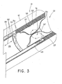
- FIG. 3 illustrates a variation of the embodiment of FIGS. 2A-2B .
- the expandable member is in the nature of an expandable balloon 51.
- the expandable balloon may be formed of any conventional balloon material in use in the medical arts, such as silicone.
- passageways 30, 40 there are many ways to form passageways 30, 40 in body tube 12.
- passageways 30, 40 are formed in the wall of body tube 12.
- Such passageways may be formed by any conventional techniques, such as insert molding, extrusion, etc., and are dimensioned to allow sufficient fluid to pass therethrough to carry out the actions described above.
- a tubular body may have a wall thickness of about 2 to 5 mm.
- passageways 30 and 40 may each have a diameter of about 0.5 to 2 mm.
- the dimensions provided herein are only examples, and that the dimensions of the body tube, passageways, etc., may be varied as desired for a particular application.
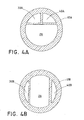
- FIGS. 4A and 4B illustrate sectional views of alternative embodiments of body tube 12A, 12B wherein respective passageways 30A, 40A ( FIG. 4A ) and 30B, 40B ( FIG. 4B ) are branched off from body tube lumen 26.
- FIGS. 4A and 4B illustrate sectional views of alternative embodiments of body tube 12A, 12B wherein respective passageways 30A, 40A ( FIG. 4A ) and 30B, 40B ( FIG. 4B ) are branched off from body tube lumen 26.
- FIG. 5 illustrates another example of the expandable member.
- the expandable member is a balloon 70.
- the balloon is shown in a non-expanded configuration in the sectional view depicted in the figure.
- longitudinal edges 72 of the balloon material 71 are sealed along a length of inner surface 27 of the body tube 12, and the uninflated balloon is positioned along one side of the inner surface.
- the distal end 42 of the second passageway 40 is positioned at a location proximate the intermediate region 73 of the balloon material 71 between the sealed edges 72.
- Balloon 70 may have a length, for example, of about 5 to 15 mm along the inner body tube surface 27.
- First passageway 30 is proximal of balloon 70, as shown in FIGS. 2A , 2B so that fluid 62 flows in the same manner as shown and described with reference to the embodiment of FIG. 2 B.
- a suitable fluid pressure introduced through distal end 42 of second passageway 40 within the intermediate region 73 can facilitate expansion of the intermediate balloon region 73 (as shown by the arrows) from the non-expanded configuration as shown, to an expanded configuration across the drainage lumen 26 (shown in dashed lines in FIG. 5 ).
- the expanded balloon forms a seal across the lumen.
- the inflated diameter of the balloon is selected in view of the size of the drainage lumen.
- the fluid pressure can be provided with the introduction of inflation fluid via the fluid coupling 46 and second passageway 40.
- the seal provided by the expanded balloon 70 is suitable to occlude the drainage lumen, preventing substantially any fluid 62 from the distal end of the first passageway 30 from exiting out from the distal end opening of the drainage lumen 26 during flushing or irrigation.
- the expandable members for use herein can be made of any conventional materials used in construction of expandable members for medical purposes.
- materials include, but are not limited to, polyethylene terephthalate (PET), polyamide (nylon), polyether block amide, polyurethane, polyethylene, low-pressure elastic materials such as silicone, or higher pressure inelastic materials.
- PET polyethylene terephthalate
- nylon polyamide
- polyether block amide polyurethane
- polyethylene polyethylene
- low-pressure elastic materials such as silicone, or higher pressure inelastic materials.
- Such materials can conveniently have an average burst pressure of, for example, between about ten and twenty bars.
- the respective positions of the second passageway and the expandable member may be modified such that the expandable member is located external to the drainage lumen at the distal end opening, rather than internally as shown.
- FIGS. 6 - 7B illustrate another example of a body tube having an occlusion member.
- the occlusion member comprises a constriction device 100 for constricting a distal end portion of lumen 26.
- the constriction device 100 includes an elongated body 120 having a proximal end 122 and a distal end 124.
- a snare member 140 is coupled to the distal end 124 of the elongated body 120.
- FIG. 6 illustrates the proximal end 44 of the second passageway 40 as a tubular member 105.
- the second passageway 40 may have a hemostatic seal 110 provided at the end of tubular member 105 to inhibit fluid loss therethrough.
- Elongated body 120 is sized to extend through the second passageway 40, wherein proximal end 122 exits out of the proximal end of second passageway 40 through the hemostatic seal 110.
- the body 120 may comprise a solid member, a tubular member, or any combination thereof, as made from, e.g., a metal, a metal alloy, a polymer, or a composite material that may include a combination of the foregoing.
- the body 120 is configured to have sufficient axial force transmission from the proximal end 122 to the distal end 124 to permit pushing or pulling of the body 120 from the proximal end.
- Proximal end 122 can be provided with a handle 125 to facilitate gripping of the body 120 during operation thereof.
- FIGS. 7A-7B depict the distal end 22 of the body tube 12. These figures illustrate one manner in which the distal end 129 of an occlusion member, such as constriction device 100, is configured to move between a constricted configuration for forming a seal within the drainage lumen, and a non-constricted configuration.
- the distal end 42 of the second passageway 40 can extend through the distal end of body tube 12, or through the distal outer surface 130 of the body tube.
- the distal end 124 of the elongated body 120 is coupled to a snare member 140.
- the snare member 140 circumferentially encloses the body tube 12. The circumference of snare member 140 is reduced, or constricted, ( FIG. 7A to FIG.
- a groove or channel 132 may be formed in the outer surface 130 of the body tube 12 to contain and guide the radial constriction of the snare member 140.
- the elongated body 120 and the snare member 140 may be formed integrally from a single element.
- the distal end 124 of the elongated body 120 can be looped, and a length of the elongated body 120 adjacent to the looped distal end can be wrapped around the circumference of the body tube 12 to define the snare member 140.
- a portion 142 of the elongated body 120 can be inserted within the opening formed by the looped distal end, and redirected to the distal end 42 of the second passageway 40.
- a withdrawing force to the proximal end 122 of the elongated body 120, the force can be axially translated to the distal end 124 such that snare member 140, and thereby body tube 12, are constricted to the configuration shown in FIG. 7 B.
- a locking or clamping device 150 such as a hemostat, can be provided at the proximal end of the elongated body 120 to selectively retain the relative position of the elongated body 120 in the constricted configuration.
- a flushing or irrigation fluid may then be introduced into the lumen via distal end 32 of the first passageway 30 for dislodging, dissolving, and/or breaking up debris formed within the drainage lumen proximal of distal end 32, as described above.
- the locking device 150 is fixedly attached around the elongated body 120, against the proximal end of the member 105.
- the locking device is removable from the elongated body to allow the elongated body to move relative to the second passageway and to permit the distal end 129 to move to the non-constriction configuration.
- the medical tube need not be a chest tube, and the following example is only intended to describe one possible use of the system.
- the chest tube may be inserted into the pleural space utilizing various techniques, such as the well-known Seldinger technique.
- Seldinger technique a needle having a bore therethrough is initially advanced into the pleural space.
- a wire guide is inserted through the bore of the needle, and the needle is thereafter removed, leaving the distal end of the wire guide positioned in the pleural space.
- a series of tapered dilators (such as three) are sequentially advanced (small to large) over the wire guide to dilate the tissue of the chest wall, and form an opening, or stoma, of desired size.
- the chest tube After removal of the largest dilator, the chest tube, which can have an inserter/obturator, is placed over the wire guide, and the distal end of the chest tube is directed into the pleural space. The proximal end of the chest tube remains outside the body.
- the proximal end of the chest tube can be coupled to the canister tube via a coupling device in a sealed manner as conventionally performed.
- a negative pressure source such as a vacuum or other suction source, is coupled to the chest tube. The negative pressure source can draw fluids out of the pleural space and into the drainage canister to be disposed of or collected, and also to sustain the normal physiologic negative pressure within the chest.
- the occlusion member can be activated to clear occlusions or other debris from the drainage lumen of the chest tube.
- a fluid 62 is introduced through the first passageway 30 to flush through the drainage lumen, e.g., as shown in FIG. 2 B.
- the fluid will dislodge, dissolve, and/or breakup debris, e.g., blood clots, mucus, etc., formed within the drainage lumen 26.
- the negative pressure source assists in drawing the excess fluid and the debris from the drainage lumen and into the drainage canister to be disposed of or collected.
- the occlusion member can be located anywhere along the length of the drainage lumen of the body tube. However, as described herein, it is preferred that the occlusion member is positioned at or near the distal end of the drainage lumen so that as large an area as possible of the inner surface of the drainage lumen can be cleared via the flushing fluid.
- a urinary catheter or tube may include the arrangements described herein to clear the catheter of obstructions (e.g., salt crystals, blood clots, etc.) that may form therein.
- obstructions e.g., salt crystals, blood clots, etc.
Landscapes
- Health & Medical Sciences (AREA)
- Heart & Thoracic Surgery (AREA)
- Biomedical Technology (AREA)
- Hematology (AREA)
- Pulmonology (AREA)
- Vascular Medicine (AREA)
- Engineering & Computer Science (AREA)
- Anesthesiology (AREA)
- Oral & Maxillofacial Surgery (AREA)
- Surgery (AREA)
- Life Sciences & Earth Sciences (AREA)
- Animal Behavior & Ethology (AREA)
- General Health & Medical Sciences (AREA)
- Public Health (AREA)
- Veterinary Medicine (AREA)
- External Artificial Organs (AREA)
- Media Introduction/Drainage Providing Device (AREA)
Applications Claiming Priority (1)
| Application Number | Priority Date | Filing Date | Title |
|---|---|---|---|
| US13/309,938 US9707325B2 (en) | 2011-12-02 | 2011-12-02 | Drainage system with occlusion member |
Publications (2)
| Publication Number | Publication Date |
|---|---|
| EP2599509A2 true EP2599509A2 (fr) | 2013-06-05 |
| EP2599509A3 EP2599509A3 (fr) | 2013-07-31 |
Family
ID=47257714
Family Applications (1)
| Application Number | Title | Priority Date | Filing Date |
|---|---|---|---|
| EP12275177.9A Withdrawn EP2599509A3 (fr) | 2011-12-02 | 2012-11-19 | Système de drainage avec dispositif d'occlusion |
Country Status (2)
| Country | Link |
|---|---|
| US (1) | US9707325B2 (fr) |
| EP (1) | EP2599509A3 (fr) |
Cited By (1)
| Publication number | Priority date | Publication date | Assignee | Title |
|---|---|---|---|---|
| EP3691601A4 (fr) * | 2018-12-28 | 2020-08-12 | Sainath Intellectual Properties, LLC | Cathéter avec valve à ballonnet |
Family Cites Families (27)
| Publication number | Priority date | Publication date | Assignee | Title |
|---|---|---|---|---|
| US3416532A (en) | 1964-07-24 | 1968-12-17 | Grossman Alan Richard | Drainage tube with means for scraping away debris therewithin |
| US4303100A (en) * | 1978-12-18 | 1981-12-01 | Geosource Inc. | Kelly valve |
| DE3035243C2 (de) | 1980-09-18 | 1982-12-30 | Udo Dr.med. 5000 Köln Uekermann | Intestinalsonde |
| US4634443A (en) * | 1985-07-05 | 1987-01-06 | Habley Medical Technology Corporation | Single circuit elastofluidic sphincter |
| US4813929A (en) | 1987-02-19 | 1989-03-21 | Neal Semrad | Chest tube device and method of inserting device |
| US5188618A (en) | 1991-05-03 | 1993-02-23 | Thomas Bruce W | Thrombus-mobilizing thoracostomy tube |
| US5279567A (en) | 1992-07-02 | 1994-01-18 | Conmed Corporation | Trocar and tube with pressure signal |
| CA2151259C (fr) | 1993-01-07 | 2008-04-01 | Gwyn F. Mcneely | Catheter de gastrostomie |
| US5509909A (en) | 1994-10-06 | 1996-04-23 | Moy; Grant G. | Bent chest tube assembly |
| US5653230A (en) | 1996-01-19 | 1997-08-05 | Cook Incorporated | Percutaneous balloon dilational tracheostomy tube |
| US5895398A (en) | 1996-02-02 | 1999-04-20 | The Regents Of The University Of California | Method of using a clot capture coil |
| US5897534A (en) | 1996-08-29 | 1999-04-27 | Team Medical, Llc | Body fluids and solids drainage system |
| US6511492B1 (en) | 1998-05-01 | 2003-01-28 | Microvention, Inc. | Embolectomy catheters and methods for treating stroke and other small vessel thromboembolic disorders |
| US6183450B1 (en) | 1999-06-04 | 2001-02-06 | William A Lois | Catheter de-clogging device |
| WO2001012086A1 (fr) | 1999-08-13 | 2001-02-22 | The Johns Hopkins University | Dispositif et methode pour l'insertion rapide d'un drain thoracique |
| WO2004030600A2 (fr) | 2002-09-30 | 2004-04-15 | Damage Control Surgical Technologies, Inc. | Methode et dispositif de drainage thoracique a deploiement rapide |
| US7036510B2 (en) | 2003-04-28 | 2006-05-02 | Cook Critical Care Incorporated | Percutaneous tracheostomy balloon apparatus |
| CA2565303C (fr) | 2003-05-02 | 2011-11-01 | Metolius Biomedical, Llc | Enlevement de debris d'un drain place dans un espace du corps |
| US7229433B2 (en) | 2003-09-08 | 2007-06-12 | Mullen Gary J | Apparatus for treating pneumothorax and/or hemothorax |
| EP1727581A1 (fr) | 2004-03-23 | 2006-12-06 | Cook Critical Care Incorporated | Ballonnet d'introducteur percutane |
| US8663236B2 (en) | 2005-04-26 | 2014-03-04 | Usgi Medical Inc. | Transgastric abdominal access |
| GB2425483A (en) | 2005-04-29 | 2006-11-01 | Hans-Ulrich Laasch | A single step trocar based insertion device |
| US8529497B2 (en) | 2007-12-04 | 2013-09-10 | Jae-Hwang Kim | Apparatus and method for controlling fecal diverting device |
| US8246752B2 (en) | 2008-01-25 | 2012-08-21 | Clear Catheter Systems, Inc. | Methods and devices to clear obstructions from medical tubes |
| CA3166875A1 (fr) | 2008-01-25 | 2009-10-01 | The Cleveland Clinic Foundation | Procedes et dispositifs destines a l'elimination d'obstructions de tubullures medicales |
| US20110152920A1 (en) | 2008-12-02 | 2011-06-23 | Rapid Medical Ltd. | Embolectomy device |
| US20110152874A1 (en) | 2009-12-21 | 2011-06-23 | Cook Critical Care Incorporated | Balloon dilational chest tube method and system |
-
2011
- 2011-12-02 US US13/309,938 patent/US9707325B2/en active Active
-
2012
- 2012-11-19 EP EP12275177.9A patent/EP2599509A3/fr not_active Withdrawn
Non-Patent Citations (1)
| Title |
|---|
| None |
Cited By (2)
| Publication number | Priority date | Publication date | Assignee | Title |
|---|---|---|---|---|
| EP3691601A4 (fr) * | 2018-12-28 | 2020-08-12 | Sainath Intellectual Properties, LLC | Cathéter avec valve à ballonnet |
| US11369547B2 (en) | 2018-12-28 | 2022-06-28 | SaiNath Intelleotual Properties, LLC | Catheter with balloon valve |
Also Published As
| Publication number | Publication date |
|---|---|
| EP2599509A3 (fr) | 2013-07-31 |
| US9707325B2 (en) | 2017-07-18 |
| US20130144269A1 (en) | 2013-06-06 |
Similar Documents
| Publication | Publication Date | Title |
|---|---|---|
| JP7005032B2 (ja) | 医療用チューブの清掃 | |
| US11850349B2 (en) | Vacuum transfer tool for extendable catheter | |
| US20200253687A1 (en) | Body-space drainage-tube debris removal | |
| EP3753599B1 (fr) | Systèmes de traitement d'un accident cérébral ischémique aigu | |
| US20120271231A1 (en) | Aspiration thrombectomy device | |
| CN110996819A (zh) | 用于子宫填塞组件的导引器及其使用方法 | |
| JP2021084030A (ja) | 調製不要なバルーン・ガイド・カテーテル | |
| US10300179B2 (en) | Tubular drainage device | |
| US9750517B2 (en) | Method of aspirating a thrombus accumulation between a venous valve and a vein wall | |
| US9707325B2 (en) | Drainage system with occlusion member | |
| US11058848B2 (en) | Catheter including expandable member | |
| WO2023104923A1 (fr) | Extraction de matériau thrombotique | |
| JP2005287809A (ja) | 医療用具 | |
| ZA200509801B (en) | Body-space drainage-tube debris removal |
Legal Events
| Date | Code | Title | Description |
|---|---|---|---|
| PUAI | Public reference made under article 153(3) epc to a published international application that has entered the european phase |
Free format text: ORIGINAL CODE: 0009012 |
|
| AK | Designated contracting states |
Kind code of ref document: A2 Designated state(s): AL AT BE BG CH CY CZ DE DK EE ES FI FR GB GR HR HU IE IS IT LI LT LU LV MC MK MT NL NO PL PT RO RS SE SI SK SM TR |
|
| AX | Request for extension of the european patent |
Extension state: BA ME |
|
| PUAL | Search report despatched |
Free format text: ORIGINAL CODE: 0009013 |
|
| AK | Designated contracting states |
Kind code of ref document: A3 Designated state(s): AL AT BE BG CH CY CZ DE DK EE ES FI FR GB GR HR HU IE IS IT LI LT LU LV MC MK MT NL NO PL PT RO RS SE SI SK SM TR |
|
| AX | Request for extension of the european patent |
Extension state: BA ME |
|
| RIC1 | Information provided on ipc code assigned before grant |
Ipc: A61M 1/00 20060101AFI20130624BHEP |
|
| STAA | Information on the status of an ep patent application or granted ep patent |
Free format text: STATUS: THE APPLICATION IS DEEMED TO BE WITHDRAWN |
|
| 18D | Application deemed to be withdrawn |
Effective date: 20140201 |