EP2597833A1 - Method and a device for estimating a link between a source and a receiver using SC-FDMA - Google Patents
Method and a device for estimating a link between a source and a receiver using SC-FDMA Download PDFInfo
- Publication number
- EP2597833A1 EP2597833A1 EP11190302.7A EP11190302A EP2597833A1 EP 2597833 A1 EP2597833 A1 EP 2597833A1 EP 11190302 A EP11190302 A EP 11190302A EP 2597833 A1 EP2597833 A1 EP 2597833A1
- Authority
- EP
- European Patent Office
- Prior art keywords
- matrix
- data symbols
- symbols
- fourier transform
- discrete fourier
- Prior art date
- Legal status (The legal status is an assumption and is not a legal conclusion. Google has not performed a legal analysis and makes no representation as to the accuracy of the status listed.)
- Granted
Links
Images


Classifications
-
- H—ELECTRICITY
- H04—ELECTRIC COMMUNICATION TECHNIQUE
- H04L—TRANSMISSION OF DIGITAL INFORMATION, e.g. TELEGRAPHIC COMMUNICATION
- H04L25/00—Baseband systems
- H04L25/02—Details ; arrangements for supplying electrical power along data transmission lines
- H04L25/0202—Channel estimation
- H04L25/022—Channel estimation of frequency response
-
- H—ELECTRICITY
- H04—ELECTRIC COMMUNICATION TECHNIQUE
- H04L—TRANSMISSION OF DIGITAL INFORMATION, e.g. TELEGRAPHIC COMMUNICATION
- H04L25/00—Baseband systems
- H04L25/02—Details ; arrangements for supplying electrical power along data transmission lines
- H04L25/0202—Channel estimation
- H04L25/0224—Channel estimation using sounding signals
- H04L25/0228—Channel estimation using sounding signals with direct estimation from sounding signals
- H04L25/023—Channel estimation using sounding signals with direct estimation from sounding signals with extension to other symbols
- H04L25/0236—Channel estimation using sounding signals with direct estimation from sounding signals with extension to other symbols using estimation of the other symbols
-
- H—ELECTRICITY
- H04—ELECTRIC COMMUNICATION TECHNIQUE
- H04L—TRANSMISSION OF DIGITAL INFORMATION, e.g. TELEGRAPHIC COMMUNICATION
- H04L25/00—Baseband systems
- H04L25/02—Details ; arrangements for supplying electrical power along data transmission lines
- H04L25/0202—Channel estimation
- H04L25/024—Channel estimation channel estimation algorithms
- H04L25/0242—Channel estimation channel estimation algorithms using matrix methods
Definitions
- the present invention relates generally to a method and a device for estimating a link between a source and a receiver using single carrier frequency division multiple access (SC-FDMA) scheme also known as discrete Fourier transform-spread orthogonal frequency division multiplex (DFT-S-OFDM) scheme.
- SC-FDMA single carrier frequency division multiple access
- DFT-S-OFDM discrete Fourier transform-spread orthogonal frequency division multiplex
- the link is for example a wireless link or a wired link like used in power line communication.
- SC-FDMA Single-carrier FDMA
- SC-FDMA Single-carrier FDMA
- OFDMA orthogonal frequency division multiple access
- guard intervals with cyclic repetition are introduced between blocks of symbols in view to efficiently eliminate time spreading caused by multi-path propagation among blocks of symbols.
- SC-FDMA The distinguishing feature of SC-FDMA is that it leads to a single-carrier transmit signal, when appropriate sub-carriers are used, in contrast to OFDMA which is a multi-carrier transmission scheme.
- sub-carriers which are equally spaced.
- the reasoning lies in the fact that while in OFDM the transmit symbols directly modulate the multiple sub-carriers, in SC-FDMA the transmit symbols are first pre-processed by a DFT block.
- channel estimation especially benefits from data-aided methods requiring a feedback from the channel decoder.
- the iterative expectation-maximization is one of them.
- Data aided channel estimation is beneficial in a receiver implementing the iterative or turbo principle.
- the turbo principle is based on the exchange of soft information between different modules. The soft information at the output of one block is fed to another block as a priori information and the latter block uses this additional information in order to boost its performance.
- At least one of the blocks is a decoder and interleaving of the coded bits is beneficial in order to make the soft information on two adjacent bits as much independent as possible.
- the turbo principle can be applied on the channel estimation. After soft detection, data symbols are used as pilots to refine the channel estimation. However, a mechanism is needed to inform the estimator on how far it should trust these "new pilots" and this is the way soft information is used.
- the soft detection does not only provide the most probable modulation symbol, but also its a posteriori probability and the a posteriori probability of other modulation symbols. Thus, the channel estimator block knows which "pilots" it should trust most.
- the present invention aims at providing a method and a device which enable an iterative estimation of a channel impulse response by a receiver.
- the present invention concerns a method for estimating a channel impulse response between a source and a receiver, data transmitted by the source being coded and organized as data symbols, data symbols being converted from serial to parallel and spread in the frequency domain by a Discrete Fourier Transform, the data symbols spread in the frequency domain being mapped on P sub-carriers allocated for transmission among N sub-carriers of a frequency band, transformed back in the time domain by an Inverse Discrete Fourier Transform module, parallel to serial converted and transferred to the receiver under the form of signals representative of data symbols, characterized in that the method comprises the steps, executed by the receiver of:
- the present invention also concerns a device for estimating a channel impulse response between a source and a receiver, data transmitted by the source being coded and organized as data symbols, symbols being converted from serial to parallel and spread in the frequency domain by a Discrete Fourier Transform, the data symbols spread in the frequency domain being mapped on P sub-carriers allocated for transmission among N sub-carriers of a frequency band, transformed back in the time domain by an Inverse Discrete Fourier Transform module, parallel to serial converted and transferred to the receiver under the form of signals representative of data symbols, characterized in that the device is included in the receiver and comprises:
- the channel estimation is improved from one iteration to another, by efficiently using the a posteriori probabilities that the transferred data symbols are equal to possible modulation symbols of the modulation scheme.
- ⁇ 1 is the 1-th modulation symbol of the possible modulation symbols
- M is the total number of possible modulation symbols
- (.) * denotes the conjugate of (.).
- ⁇ is a matrix with size PxL, built from the L first columns of a non-normalized DFT matrix ⁇ N with size NxN and the P rows of the matrix ⁇ N corresponding to allocated subcarriers
- diag(.) denotes a diagonal matrix, in which vector (.) is the diagonal, F is the Discrete Fourier Transform matrix, (.) ⁇ denotes the transpose conjugate of (.)
- R FX is the second matrix and Y is a size- P vector of demapped received data symbols, X being determined from a posteriori probabilities that data symbol X k equals ⁇ 1 , ⁇ 1 being the 1-th modulation symbol of the possible modulation symbols.
- implementation complexity reduction is achieved by only computing diagonal coefficients of the channel impulse response, since non-diagonal of the third matrix are not used for creating the second matrix.
- the source further transfers pilot symbols spread in the frequency domain by the Discrete Fourier Transform and the receiver sets the a posteriori probability of each pilot symbol to the value one for the symbol value equal to the pilot symbol and to the value zero for other symbol values.
- the pilot symbols can be used in each iteration, improving the channel estimation beyond what would be achieved by only using a posteriori probabilities that the transferred data symbols are equal to possible modulation symbols of the modulation scheme.
- the source further transfers pilot symbols not spread in the frequency domain by the Discrete Fourier Transform and in that the method comprises further steps of :
- the pilot symbols can be used in each iteration, improving the channel estimation beyond what would be achieved by only using a posteriori probabilities that the transferred data symbols are equal to possible modulation symbols of the modulation scheme.
- pilot symbols which are not spread in the frequency domain will enable more efficient initial channel estimation on pilot symbols.
- the channel estimation is dependent of the second matrix as being calculated from the trace of the second matrix.
- ⁇ k,l' is the coefficient at k-th row and /'-th column of the first matrix ⁇
- Y k is the k-th coefficient of a size P vector of demapped received data symbols
- (.) ⁇ denotes the transpose conjugate of (.)
- (.) * denotes the conjugate of (.)
- the source further transfers pilot symbols spread in the frequency domain by the Discrete Fourier Transform and the receiver sets the a posteriori probability of each pilot symbol to the value one for the symbol value equal to the pilot symbol and to the value zero for other symbol values.
- the pilot symbols can be used in each iteration, improving the channel estimation beyond what would be achieved by only using a posteriori probabilities that the transferred data symbols are equal to possible modulation symbols of the modulation scheme.
- the source further transfers pilot symbols not spread in the frequency domain by the Discrete Fourier Transform and in that the channel impulse response is further dependent of the sum of the energies of the pilot symbols.
- pilot symbols can be used in each iteration, improving the channel estimation beyond what would be achieved by only using a posteriori probabilities that the transferred data symbols are equal to possible modulation symbols of the modulation scheme. Having pilot symbols which are not spread in the frequency domain will enable more efficient initial channel estimation on pilot symbols.
- the channel impulse response is estimated iteratively a predetermined number of times.
- the channel estimation complexity is bounded, the predetermined number of iterations being determined in order to obtain a given channel estimation improvement of iterative channel estimation compared to non-iterative channel estimation. Furthermore, iterating beyond a certain number of iterations does not bring further significant channel estimation performance improvement.
- the present invention concerns a computer program which can be directly loadable into a programmable device, comprising instructions or portions of code for implementing the steps of the method according to the invention, when said computer program is executed on a programmable device.
- Fig. 1 represents a link in which the present invention is implemented.
- the signals transferred by a source Src are transferred to one or plural receivers Rec.
- the link may be a wireless link or a wired link like used in power line communication.
- a source Src may be included in a satellite or in a terrestrial transmitter like a base station or in a terminal like a mobile phone or in a relay.
- the receiver Rec may be a mobile terminal to which data like video signals are broadcasted or a mobile terminal which is in communication with a remote telecommunication device like a mobile phone or with a server or a base station or a home base station which receives signals from a mobile terminal or a relay.
- the receiver :
- Fig. 2 is a diagram representing the architecture of a receiver in which the present invention is implemented.
- the receiver Rec has, for example, an architecture based on components connected together by a bus 201 and a processor 200 controlled by the program as disclosed in Fig. 5 or 6 or 8 or 9 .
- the receiver Rec may have an architecture based on dedicated integrated circuits.
- the bus 201 links the processor 200 to a read only memory ROM 202, a random access memory RAM 203 and a network interface 205.
- the memory 203 contains registers intended to receive variables and the instructions of the program related to the algorithm as disclosed in Fig. 5 or 6 or 8 or 9 .
- the processor 200 controls the operation of the network interface 205.
- the read only memory 202 contains instructions of the program related to the algorithm as disclosed in Fig. 5 or 6 or 8 or 9 , which are transferred, when the receiver Rec is powered on, to the random access memory 203.
- the network interface 205 comprises means for transferring multiplexed data symbols and pilot sequences according to the invention to receivers Rec.
- the network interface 205 comprises components as disclosed in Fig. 3 .
- Fig. 3 discloses a block diagram of components of a network interface of the receiver according to the present invention.
- data to be transmitted are coded and organized as data symbols by a coding and modulation module giving a set of data symbols.
- Data symbols are converted from serial to parallel and spread in the frequency domain by a DFT (Discrete Fourier Transform).
- the data symbols spread in the frequency domain are mapped on sub-carriers comprised in the allocated frequency band.
- the symbols outputted after the frequency mapping are transformed back in the time domain by a IDFT (Inverse Discrete Fourier Transform) module and parallel to serial converted.
- IDFT Inverse Discrete Fourier Transform
- An optional cyclic prefix insertion module can be applied before transmission.
- At least one signal 305 is received from at least one receive antenna.
- the received signal is synchronized by a synchronization module not shown in Fig. 3 .
- the optional cyclic prefix removal module 300 removes the cyclic prefix, if needed, from the synchronized signal.
- the serial to parallel module 301 parallelizes the received signal.
- the DFT module 302 executes a DFT of size N on the parallelized signal.
- the signals provided by the DFT module 302 are demapped from N to P if the number of allocated subcarriers is equal to P, N being the total amount of available subcarriers. It is has to noted here that, for simplification purpose, P is taken equal to N in the following.
- Demapped symbols are transferred to the channel estimation module 310 according to the present invention.
- the channel estimation module 310 is described in reference to Fig. 4 .
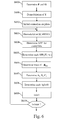
- Fig. 4 discloses a block diagram of components of a channel estimation module according to the present invention.
- the demodulation module 400 demodulates the received symbols into a stream of observations on coded bits.
- the demodulation module 400 performs also an equalization and an inverse DTF.
- the observations on coded bits are deinterleaved, if needed, by a deinterleaver module 401.
- the bits are interleaved in order to make the soft information on two adjacent bits in a codeword as much independent as possible.
- the coded bits are decoded by a soft-input soft-output (SISO) module 402 which provides a posteriori probabilities of coded bits.
- SISO soft-input soft-output
- the output of the SISO module is interleaved by the interleaver 403 if needed and modulated by the modulation module 404 in order to provide a posteriori probabilities of data symbols.
- the a posteriori probabilities of data symbols are then provided to the EM channel estimation module 405 as a priori information, according to the present invention.
- EM channel estimation module 405 provides a recursive solution to maximum-likelihood (ML) estimation.
- the channel impulse response is sampled at a given sampling frequency. Each sample of the channel impulse response is called a tap.
- ⁇ is a matrix with size PxL, built from the L first columns of a non-normalized DFT matrix ⁇ N with size NxN, N being the number of available sub-carriers of the frequency band and L the number of taps assumed in the channel impulse response:
- ⁇ N 1 1 ⁇ 1 1 1 e - j ⁇ 2 ⁇ ⁇ ⁇ 1 N ⁇ e - j ⁇ 2 ⁇ ⁇ ⁇ N - 1 N ⁇ ⁇ ⁇ ⁇ 1 e - j ⁇ 2 ⁇ ⁇ ⁇ N - 1 N ⁇ e - j ⁇ 2 ⁇ ⁇ ⁇ N - 1 N ⁇ e j ⁇ 2 ⁇ ⁇ ⁇
- ⁇ denotes the transpose conjugate of (.)
- diag(.) denotes a diagonal matrix, in which vector (.) is the diagonal and Y is the size-P vector of the observations on modulation symbols, observed after module 303.
- the modulation is a Quadrature Phase-Shift Keying (QPSK) modulation
- QPSK Quadrature Phase-Shift Keying
- ⁇ 0 is selected among ⁇ 0 , ⁇ 1 , ⁇ 2 and ⁇ 3 .
- ⁇ 1 is selected among ⁇ 0 , ⁇ 1 , ⁇ 2 and ⁇ 3
- ⁇ 2 is selected among ⁇ 0 , ⁇ 1 , ⁇ 2 and ⁇ 3
- ⁇ 3 is selected among ⁇ 0 , ⁇ 1 , ⁇ 2 and ⁇ 3 .
- each element of the vector X can be easily calculated by the expression.
- the complexity of this diag ( FX ) is then reduced a lot and can be implemented in a receiver like a mobile phone or a home base station.
- 2 can be expressed as the diagonal of matrix F ⁇ ⁇ F ⁇ , i.e., F ⁇ 0 2 ...
- F ⁇ P - 1 2 T diagM F ⁇ ⁇ ⁇ F ⁇ where diagM (A) corresponds to a vector made of the elements of the diagonal of the matrix A .
- R ⁇ ⁇ APP i ⁇ ⁇ ⁇ ⁇ ⁇ ⁇
- matrix R FX is a diagonal matrix with the same diagonal as matrix FRF ⁇ , which is non-diagonal.
- R FX is the matrix FRF ⁇ ignoring the non-diagonal terms.
- 2 1/P are constant terms and can be stored in a lookup table.
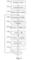
- Fig. 5 discloses an example of an algorithm executed by a receiver according to a first mode of realization of the present invention.
- the algorithm is executed by the processor 200 of the receiver Rec or by the wireless interface 205 of the receiver Rec.
- the present algorithm is executed periodically, for example every 71 microseconds or every millisecond.
- the link between the source Src and the receiver Rec is determined only from received data symbols.
- step S500 the non-normalized DFT matrix ⁇ with size PxL, the DFT matrix F are determined and a variable i is set to null value.
- next step S501 the received symbols are demodulated in order to produce vector Y .
- cyclic prefix may be removed, a serial to parallel conversion is performed and a demapping is performed.
- the initial estimation is performed, for instance on pilot symbols, by a usual non-iterative estimation method, such as a least-square (LS) estimation or a minimum mean square channel (MMSE) estimation.
- a usual non-iterative estimation method such as a least-square (LS) estimation or a minimum mean square channel (MMSE) estimation.
- step S503 a demodulation of the SC-FDMA symbols is performed.
- an equalization and an inverse DFT are also performed.
- a posteriori probabilities APP i (b) of each coded bit b are determined.
- the coded bits are disclosed in Fig. 7 .
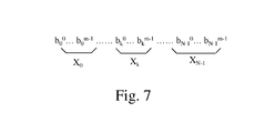
- Fig. 7 represents the relationship between coded bits and modulation symbols.
- the coded bits are grouped into modulation symbols X 0 ..., X k ,...X P-1 .
- the symbol X 0 comprises the bits b 0 0 to b 0 m-1
- the symbol X k comprises the bits b k 0 to b k m-1
- R FX diag diagM FRF ⁇
- 2 1/P are constant terms and can be stored in a lookup table.
- h i + 1 ⁇ ⁇ ⁇ R FX ⁇ ⁇ - 1 ⁇ ⁇ ⁇ ⁇ diag ⁇ FX ⁇ ⁇ Y
- variable i is compared to a predetermined value imax which is for example comprised between three and ten.
- the predetermined value imax is for example equal to eight.
- step S503 If the variable i is lower than imax, the algorithm returns to step S503 in order to start the following iteration. Otherwise, the algorithm is interrupted.
- the present algorithm is also applicable when pilot symbols are processed at the source by a DFT module in the same way as data symbols.
- steps S504 and S505 are performed only for the data symbols and the a posteriori probability APP i (X p ) of each pilot symbol X p is set to the value one for the symbol value equal to the pilot symbol and to the value zero for other symbol values as pilot symbol is known by the receiver Rec.
- Fig. 6 discloses an example of an algorithm executed by a receiver according to a second mode of realization of the present invention.
- the algorithm is executed by the processor 200 of the receiver Rec or by the wireless interface 205 of the receiver Rec.
- the present algorithm is executed periodically, for example every 71 microseconds or every millisecond.
- the link between the source Src and the receiver Rec or in other words the channel impulse response is determined only from received data symbols.
- step S600 the non-normalized DFT matrix ⁇ with size PxL, the DFT matrix F are determined and a variable i is set to null value.
- next step S601 the received data symbols are demodulated in order to produce vector Y .
- cyclic prefix may be removed, a serial to parallel conversion is performed and a demapping is performed.
- an initial estimation of the channel is executed, for instance on pilot symbols.
- the initial estimation is performed by a usual non-iterative estimation method, such as a least-square (LS) estimation or a minimum mean square channel (MMSE) estimation.
- LS least-square
- MMSE minimum mean square channel
- step S603 a demodulation of the SC-FDMA symbols is performed.
- an equalization and an inverse DFT are also performed.
- a posteriori probabilities APP i (b) of each coded bit b are determined.
- the coded bits are disclosed in Fig. 7 .
- R FX diag (diagM ( FRF ⁇ )) as disclosed at step S506.
- a l h l i ⁇ Trace R
- h l i + 1 A l + B l + C l Trace R FX
- the denominator is the trace of R FX .
- the numerator is the sum of three terms A 1 +B 1 +C 1 .
- variable i is compared to a predetermined value imax which is for example comprised between three and ten.
- the predetermined value imax is for example equal to eight.
- step S603 If the variable i is lower than imax, the algorithm returns to step S603 in order to start the following iteration. Otherwise, the algorithm is interrupted.
- the present algorithm is also applicable when pilot symbols are processed at the source by a DFT module in the same way as data symbols.
- steps S504 and S505 are performed only for the data symbols and the a posteriori probability APP i (Xp) of each pilot symbol X p is set to the value one for the symbol value equal to the pilot symbol and to the value zero for other symbol values as pilot symbol is known by the receiver Rec.
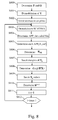
- Fig. 8 discloses an example of an algorithm executed by a receiver according to a third mode of realization of the present invention.
- the present algorithm is executed periodically, for example every 71 microseconds or every millisecond.
- the present algorithm differs from the algorithm of Fig. 5 in the sense that during the iterative process, the link between the source Src and the receiver Rec or in other word the channel impulse response is determined from received pilot symbols and from received data symbols and the pilot symbols are not processed at the source by a DFT module as data symbols and are individually mapped onto subcarriers.
- next step S801 the received data symbols and pilot symbols are demodulated in order to produce vector Y.
- cyclic prefix may be removed, a serial to parallel conversion is performed and a demapping is performed.
- the initial estimation is performed, for instance on pilot symbols, by a usual non-iterative estimation method, such as a least-square (LS) estimation or a minimum mean square channel (MMSE) estimation.
- a usual non-iterative estimation method such as a least-square (LS) estimation or a minimum mean square channel (MMSE) estimation.
- step S803 a demodulation of the SC-FDMA data symbols is performed.
- an equalization and an inverse DFT are also performed.
- a posteriori probabilities APP i (b) of each coded bit b are determined.
- the coded bits are disclosed in Fig. 7 .
- R FX diag diagM FRF ⁇
- the new matrix R x' comprises the matrix R FX and new lines at positions of subcarriers on which pilot symbols are mapped. For each received pilot symbol X p , the energy value
- step S808 diag( FX ) is determined as disclosed as step S507.
- diag( X ') takes values of diag( FX ) on lines on which data symbols are mapped and pilot symbols X p on lines on which pilot symbols are mapped.
- h i + 1 ⁇ ⁇ ⁇ R X ⁇ ⁇ ⁇ - 1 ⁇ ⁇ ⁇ ⁇ diag ⁇ X ⁇ ⁇ ⁇ Y .
- step S 811 the variable i is incremented.
- variable i is compared to a predetermined value imax which is for example comprised between three and ten.
- the predetermined value imax is for example equal to eight.
- step S803 If the variable i is lower than imax, the algorithm returns to step S803 in order to start the following iteration. Otherwise, the algorithm is interrupted.
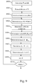
- Fig. 9 discloses an example of an algorithm executed by a receiver according to a fourth mode of realization of the present invention.
- the present algorithm is executed periodically, for example every 71 microseconds or every millisecond.
- the present algorithm differs from the algorithm of Fig. 6 in the sense that during the iterative process, the link between the source Src and the receiver Rec or in other words the channel impulse response is determined from received pilot symbols and from received data symbols and the pilot symbols are not processed at the source by a DFT module as data symbols and are individually mapped onto subcarriers.
- next step S901 the received data symbols and pilot symbols are demodulated in order to produce vector Y .
- cyclic prefix may be removed, a serial to parallel conversion is performed and a demapping is performed.
- the initial estimation is performed, for instance on pilot symbols, by a usual non-iterative estimation method, such as a least-square (LS) estimation or a minimum mean square channel estimation.
- LS least-square
- step S903 a demodulation of the SC-FDMA symbols is performed.
- an equalization and an inverse DFT are also performed.
- a posteriori probabilities APP i (b) of each coded bit b are determined.
- the coded bits are disclosed in Fig. 7 .
- k d (m) is the subcarrier of which the m-th data symbol is mapped and k p (j) is the subcarrier of which the j-th pilot symbol is mapped.
- the denominator is the trace of R FX plus the sum of the energies of the received pilot symbols.
- the numerator is the sum of three terms A 1 '+B 1 '+C 1 '.
- variable i is compared to a predetermined value imax which is for example comprised between three and ten.
- the predetermined value imax is for example equal to eight.
- step S903 If the variable i is lower than imax, the algorithm returns to step S903 in order to start the following iteration. Otherwise, the algorithm is interrupted.
Landscapes
- Engineering & Computer Science (AREA)
- Power Engineering (AREA)
- Computer Networks & Wireless Communication (AREA)
- Signal Processing (AREA)
- Physics & Mathematics (AREA)
- Mathematical Physics (AREA)
- Cable Transmission Systems, Equalization Of Radio And Reduction Of Echo (AREA)
Abstract
- determines a first matrix with size PxL, L being the number of taps and determining a Discrete Fourier Transform matrix of size PxP,
- demodulates the received signals representative of data symbols, in order to produce received data symbols,
- parallelizes the received data symbols,
- executes a Discrete Fourier Transform on the parallelized received data symbols,
- demaps the transformed received data symbols from the sub-carriers,
- estimates iteratively the channel impulse response from the demapped received data symbols, the channel estimation being dependent of the first matrix, the Discrete Fourier Transform matrix and of a second matrix which is defined according to a posteriori probabilities that the transferred data symbols are equal to possible modulation symbols of the modulation scheme.
Description
- The present invention relates generally to a method and a device for estimating a link between a source and a receiver using single carrier frequency division multiple access (SC-FDMA) scheme also known as discrete Fourier transform-spread orthogonal frequency division multiplex (DFT-S-OFDM) scheme.
- The link is for example a wireless link or a wired link like used in power line communication.
- Single-carrier FDMA (SC-FDMA) is a frequency-division multiple access scheme. Like other multiple access schemes, it deals with the assignment of multiple users to a shared communication resource. SC-FDMA can be interpreted as a linearly precoded orthogonal frequency division multiple access (OFDMA) scheme, in the sense that it has an additional DFT processing preceding the conventional OFDMA processing. Just like in OFDM, guard intervals with cyclic repetition are introduced between blocks of symbols in view to efficiently eliminate time spreading caused by multi-path propagation among blocks of symbols.
- The distinguishing feature of SC-FDMA is that it leads to a single-carrier transmit signal, when appropriate sub-carriers are used, in contrast to OFDMA which is a multi-carrier transmission scheme.
- Appropriate sub-carriers are sub-carriers which are equally spaced.
- Owing to its inherent single carrier structure, a prominent advantage of SC-FDMA over OFDM and OFDMA is that its transmit signal has a lower peak-to-average power ratio (PAPR). This low-PAPR property still holds when sub-carriers are different from the appropriate sub-carriers.
- Intuitively, the reasoning lies in the fact that while in OFDM the transmit symbols directly modulate the multiple sub-carriers, in SC-FDMA the transmit symbols are first pre-processed by a DFT block.
- As hardware capacity is continuously increasing, it becomes feasible to implement iterative receivers allowing for improvement of physical layer functions. Among these functions, channel estimation especially benefits from data-aided methods requiring a feedback from the channel decoder. The iterative expectation-maximization is one of them.
- Data aided channel estimation is beneficial in a receiver implementing the iterative or turbo principle. In iterative receivers, the turbo principle is based on the exchange of soft information between different modules. The soft information at the output of one block is fed to another block as a priori information and the latter block uses this additional information in order to boost its performance.
- At least one of the blocks is a decoder and interleaving of the coded bits is beneficial in order to make the soft information on two adjacent bits as much independent as possible.
- The turbo principle can be applied on the channel estimation. After soft detection, data symbols are used as pilots to refine the channel estimation. However, a mechanism is needed to inform the estimator on how far it should trust these "new pilots" and this is the way soft information is used. The soft detection does not only provide the most probable modulation symbol, but also its a posteriori probability and the a posteriori probability of other modulation symbols. Thus, the channel estimator block knows which "pilots" it should trust most.
- The present invention aims at providing a method and a device which enable an iterative estimation of a channel impulse response by a receiver.
- To that end, the present invention concerns a method for estimating a channel impulse response between a source and a receiver, data transmitted by the source being coded and organized as data symbols, data symbols being converted from serial to parallel and spread in the frequency domain by a Discrete Fourier Transform, the data symbols spread in the frequency domain being mapped on P sub-carriers allocated for transmission among N sub-carriers of a frequency band, transformed back in the time domain by an Inverse Discrete Fourier Transform module, parallel to serial converted and transferred to the receiver under the form of signals representative of data symbols, characterized in that the method comprises the steps, executed by the receiver of:
- determining a first matrix with size PxL, L being the number of taps assumed in the channel impulse response and determining a Discrete Fourier Transform matrix of size PxP,
- demodulating the received signals representative of data symbols, in order to produce received data symbols,
- parallelizing the received data symbols,
- executing a Discrete Fourier Transform on the parallelized received data symbols,
- demapping the transformed received data symbols from the sub-carriers,
- estimating iteratively the channel impulse response from the demapped received data symbols, the channel estimation being dependent of the first matrix, the Discrete Fourier Transform matrix and of a second matrix which is defined according to a posteriori probabilities that the transferred data symbols are equal to possible modulation symbols of the modulation scheme.
- The present invention also concerns a device for estimating a channel impulse response between a source and a receiver, data transmitted by the source being coded and organized as data symbols, symbols being converted from serial to parallel and spread in the frequency domain by a Discrete Fourier Transform, the data symbols spread in the frequency domain being mapped on P sub-carriers allocated for transmission among N sub-carriers of a frequency band, transformed back in the time domain by an Inverse Discrete Fourier Transform module, parallel to serial converted and transferred to the receiver under the form of signals representative of data symbols, characterized in that the device is included in the receiver and comprises:
- means for determining a first matrix with size PxL, L being the number of taps assumed in the channel impulse response and determining a Discrete Fourier Transform matrix of size PxP ,
- means for demodulating the received signals representative of data symbols, in order to produce received data symbols,
- means for parallelizing the received data symbols,
- means for executing a Discrete Fourier Transform on the parallelized received data symbols,
- means for demapping the transformed received data symbols from sub-carriers,
- means for estimating iteratively the channel impulse response from the demapped received data symbols, the channel estimation being dependent of the first matrix, the Discrete Fourier Transform matrix and of a second matrix which is defined according to a posteriori probabilities that the transferred data symbols are equal to possible modulation symbols of the modulation scheme.
- Thus, the channel estimation is improved from one iteration to another, by efficiently using the a posteriori probabilities that the transferred data symbols are equal to possible modulation symbols of the modulation scheme.
- According to a particular feature, the second matrix is a diagonal matrix, the elements of which being diagonal elements of a third matrix obtained from the Discrete Fourier Transform matrix and from a fourth matrix, the elements of the fourth matrix being equal to:


- Thus, all a posteriori probabilities that the transferred symbols are equal to possible modulation symbols of the modulation scheme are efficiently used by creating the fourth matrix.
- According to a particular feature, the second matrix is equal to :

- According to a particular feature, the channel impulse response at the (i+1)-th iteration is determined according to the following formula:

- According to a particular feature, only the diagonal coefficients of the third matrix are calculated.
- Thus, implementation complexity reduction is achieved by only computing diagonal coefficients of the channel impulse response, since non-diagonal of the third matrix are not used for creating the second matrix.
- According to a particular feature, the source further transfers pilot symbols spread in the frequency domain by the Discrete Fourier Transform and the receiver sets the a posteriori probability of each pilot symbol to the value one for the symbol value equal to the pilot symbol and to the value zero for other symbol values.
- Thus, the pilot symbols can be used in each iteration, improving the channel estimation beyond what would be achieved by only using a posteriori probabilities that the transferred data symbols are equal to possible modulation symbols of the modulation scheme.
- According to a particular feature, the source further transfers pilot symbols not spread in the frequency domain by the Discrete Fourier Transform and in that the method comprises further steps of :
- enlarging the second matrix into a new matrix by inserting new lines at positions of subcarriers on which pilot symbols are mapped,
- inserting, for each received pilot symbol, the energy value of the received pilot symbol in the line at element position corresponding to the diagonal of the new matrix.
- Thus, the pilot symbols can be used in each iteration, improving the channel estimation beyond what would be achieved by only using a posteriori probabilities that the transferred data symbols are equal to possible modulation symbols of the modulation scheme.
- Having pilot symbols which are not spread in the frequency domain will enable more efficient initial channel estimation on pilot symbols.
- According to a particular feature, the channel estimation is dependent of the second matrix as being calculated from the trace of the second matrix.
- Thus, a better stability of the channel estimation is obtained through iterations. Indeed, by computing the channel estimate using the trace of the second matrix, no matrix inversion is required.
- According to a particular feature, the denominator of the channel impulse response at the (i+1)-th iteration is the trace of R FX = diag (diagM (FRF† )) .
- According to a particular feature, the channel impulse response at the (i+1)-th iteration is determined according to the following formula:


(.)† denotes the transpose conjugate of (.) and (.)* denotes the conjugate of (.) - According to a particular feature, the source further transfers pilot symbols spread in the frequency domain by the Discrete Fourier Transform and the receiver sets the a posteriori probability of each pilot symbol to the value one for the symbol value equal to the pilot symbol and to the value zero for other symbol values.
- Thus, the pilot symbols can be used in each iteration, improving the channel estimation beyond what would be achieved by only using a posteriori probabilities that the transferred data symbols are equal to possible modulation symbols of the modulation scheme.
- According to a particular feature, the source further transfers pilot symbols not spread in the frequency domain by the Discrete Fourier Transform and in that the channel impulse response is further dependent of the sum of the energies of the pilot symbols.
- Thus, the pilot symbols can be used in each iteration, improving the channel estimation beyond what would be achieved by only using a posteriori probabilities that the transferred data symbols are equal to possible modulation symbols of the modulation scheme. Having pilot symbols which are not spread in the frequency domain will enable more efficient initial channel estimation on pilot symbols.
- According to a particular feature, the channel impulse response is estimated iteratively a predetermined number of times.
- Thus, the channel estimation complexity is bounded, the predetermined number of iterations being determined in order to obtain a given channel estimation improvement of iterative channel estimation compared to non-iterative channel estimation. Furthermore, iterating beyond a certain number of iterations does not bring further significant channel estimation performance improvement.
- According to still another aspect, the present invention concerns a computer program which can be directly loadable into a programmable device, comprising instructions or portions of code for implementing the steps of the method according to the invention, when said computer program is executed on a programmable device.
- Since the features and advantages relating to the computer program are the same as those set out above related to the method and apparatus according to the invention, they will not be repeated here.
- The characteristics of the invention will emerge more clearly from a reading of the following description of an example of embodiment, the said description being produced with reference to the accompanying drawings, among which :
-
Fig. 1 represents a link in which the present invention is implemented; -
Fig. 2 is a diagram representing the architecture of a receiver in which the present invention is implemented ; -
Fig. 3 discloses a block diagram of components of a network interface of the receiver according to the present invention; -
Fig. 4 discloses a block diagram of components of a channel estimation module according to the present invention; -
Fig. 5 discloses an example of an algorithm executed by a receiver according to a first mode of realization of the present invention; -
Fig. 6 discloses an example of an algorithm executed by a receiver according to a second mode of realization of the present invention; -
Fig. 7 represents the relationship between coded bits and modulation symbols; -
Fig. 8 discloses an example of an algorithm executed by a receiver according to a third mode of realization of the present invention; -
Fig. 9 discloses an example of an algorithm executed by a receiver according to a fourth mode of realization of the present invention. -
Fig. 1 represents a link in which the present invention is implemented. - The signals transferred by a source Src are transferred to one or plural receivers Rec.
- The link may be a wireless link or a wired link like used in power line communication.
- A source Src may be included in a satellite or in a terrestrial transmitter like a base station or in a terminal like a mobile phone or in a relay.
- Only one source Src is shown in the
Fig. 1 for the sake of simplicity, but the link may comprise a more important number of sources Src. - Only one receiver Rec is shown in the
Fig. 1 for the sake of simplicity, but signals may be broadcasted to a more important number of receivers Rec. - The receiver Rec may be a mobile terminal to which data like video signals are broadcasted or a mobile terminal which is in communication with a remote telecommunication device like a mobile phone or with a server or a base station or a home base station which receives signals from a mobile terminal or a relay.
- According to the invention, the receiver:
- determines a first matrix with size PxL, L being the number of taps assumed in the channel impulse response and determining a Discrete Fourier Transform matrix of size PxP,
- demodulates the received signals representative of data symbols, in order to produce received data symbols,
- parallelizes the received data symbols,
- executes a Discrete Fourier Transform on the parallelized received data symbols,
- demaps the transformed received data symbols from the sub-carriers,
- estimates iteratively the channel impulse response from the demapped received data symbols, the channel estimation being dependent of the first matrix, the Discrete Fourier Transform matrix and of a second matrix which is defined according to a posteriori probabilities that the transferred data symbols are equal to possible modulation symbols of the modulation scheme.
-
Fig. 2 is a diagram representing the architecture of a receiver in which the present invention is implemented. - The receiver Rec has, for example, an architecture based on components connected together by a
bus 201 and aprocessor 200 controlled by the program as disclosed inFig. 5 or6 or8 or9 . - It has to be noted here that the receiver Rec may have an architecture based on dedicated integrated circuits.
- The
bus 201 links theprocessor 200 to a read onlymemory ROM 202, a randomaccess memory RAM 203 and anetwork interface 205. - The
memory 203 contains registers intended to receive variables and the instructions of the program related to the algorithm as disclosed inFig. 5 or6 or8 or9 . - The
processor 200 controls the operation of thenetwork interface 205. - The read only
memory 202 contains instructions of the program related to the algorithm as disclosed inFig. 5 or6 or8 or9 , which are transferred, when the receiver Rec is powered on, to therandom access memory 203. - The
network interface 205 comprises means for transferring multiplexed data symbols and pilot sequences according to the invention to receivers Rec. - The
network interface 205 comprises components as disclosed inFig. 3 . -
Fig. 3 discloses a block diagram of components of a network interface of the receiver according to the present invention. - In SC-FDMA, data to be transmitted are coded and organized as data symbols by a coding and modulation module giving a set of data symbols. Data symbols are converted from serial to parallel and spread in the frequency domain by a DFT (Discrete Fourier Transform). The data symbols spread in the frequency domain are mapped on sub-carriers comprised in the allocated frequency band. The symbols outputted after the frequency mapping are transformed back in the time domain by a IDFT (Inverse Discrete Fourier Transform) module and parallel to serial converted.
- An optional cyclic prefix insertion module can be applied before transmission.
- At least one
signal 305 is received from at least one receive antenna. The received signal is synchronized by a synchronization module not shown inFig. 3 . - The optional cyclic
prefix removal module 300 removes the cyclic prefix, if needed, from the synchronized signal. - The serial to
parallel module 301 parallelizes the received signal. - The
DFT module 302 executes a DFT of size N on the parallelized signal. - The signals provided by the
DFT module 302 are demapped from N to P if the number of allocated subcarriers is equal to P, N being the total amount of available subcarriers. It is has to noted here that, for simplification purpose, P is taken equal to N in the following. - Demapped symbols are transferred to the
channel estimation module 310 according to the present invention. - The
channel estimation module 310 is described in reference toFig. 4 . -
Fig. 4 discloses a block diagram of components of a channel estimation module according to the present invention. - The
demodulation module 400 demodulates the received symbols into a stream of observations on coded bits. Thedemodulation module 400 performs also an equalization and an inverse DTF. - The observations on coded bits are deinterleaved, if needed, by a
deinterleaver module 401. The bits are interleaved in order to make the soft information on two adjacent bits in a codeword as much independent as possible. - The coded bits are decoded by a soft-input soft-output (SISO)
module 402 which provides a posteriori probabilities of coded bits. - The output of the SISO module is interleaved by the
interleaver 403 if needed and modulated by themodulation module 404 in order to provide a posteriori probabilities of data symbols. - The a posteriori probabilities of data symbols are then provided to the EM
channel estimation module 405 as a priori information, according to the present invention. - EM
channel estimation module 405 provides a recursive solution to maximum-likelihood (ML) estimation. - The channel impulse response is sampled at a given sampling frequency. Each sample of the channel impulse response is called a tap.
- According to the invention the channel impulse response, which is a L size vector composed of L taps, at iteration i+1 is:

where Ω is a matrix with size PxL, built from the L first columns of a non-normalized DFT matrix Ω N with size NxN, N being the number of available sub-carriers of the frequency band and L the number of taps assumed in the channel impulse response:
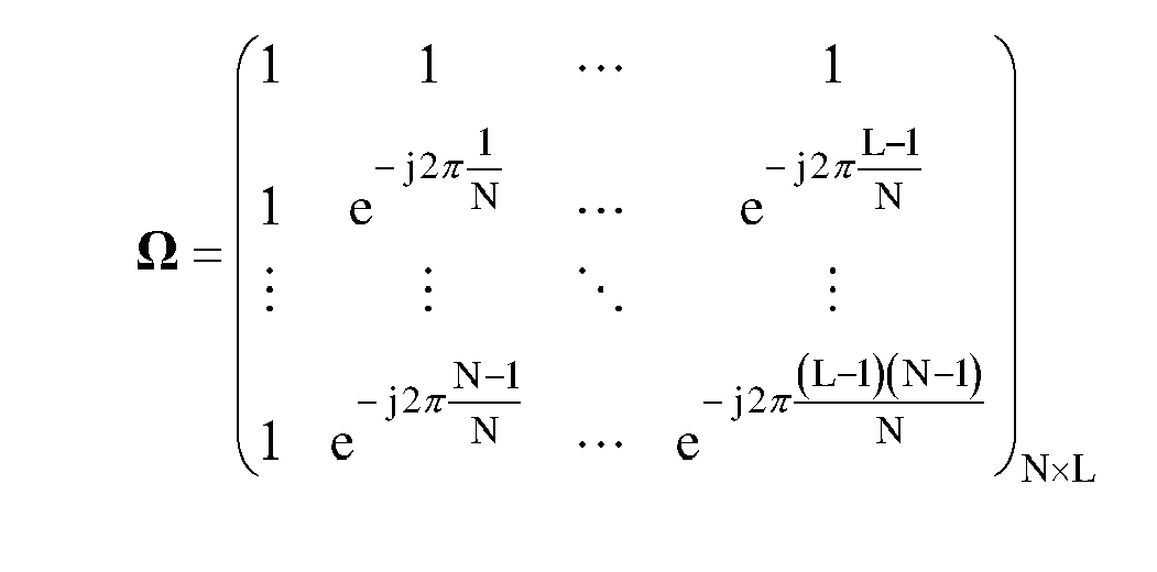
- It has to be noted here that Ω is given in an exemple where P=N.
- The elements of Ω are

module 303. - If P<N, only the lines of the matrix Ω corresponding to allocated subcarriers will be selected in order to form a new matrix Ω. For the rest of the description, P is considered to be equal to N.

α is a column vector containing plural possible modulated symbols, each possible modulation symbol belonging to the M possible modulation symbols.
- APPi(X=α) is the a posteriori probability that X takes the value of the vector α in the i-th iteration. It will be written for the sake of simplification hereinafter APPi(α).
- According to the first mode of realization, a simplified computation of diag(FX) and R FX is performed:

- Using the linearity property of the DFT, the equation is rewritten as:


- If we consider the element k of X , we have:

where α1 is the 1-th modulation symbol for a given modulation. - For example, if the modulation is a Quadrature Phase-Shift Keying (QPSK) modulation, α 0=1+j, α 1=1-j, α 2=-1-j and α 3=-1+j.
- α 0 is selected among α 0, α 1, α 2 and α 3. α1 is selected among α 0, α 1, α 2 and α 3, α 2 is selected among α 0, α 1, α 2 and α 3 and α 3 is selected among α0, α1, α2 and α 3.
- Thus, each element of the vector X can be easily calculated by the expression. The complexity of this diag (FX) is then reduced a lot and can be implemented in a receiver like a mobile phone or a home base station.
- R FX can be also simplified :


- Thus,


- Thus, matrix R FX is a diagonal matrix with the same diagonal as matrix FRF†, which is non-diagonal. In other words, R FX is the matrix FRF† ignoring the non-diagonal terms.
- The terms of matrix R are calculated as:

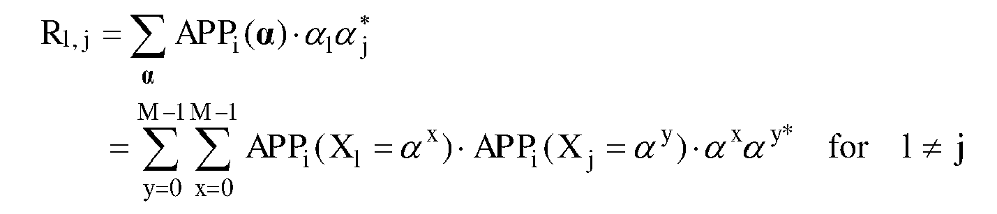
- According to a particular mode of the first mode of realization, in order to further reduce the complexity, instead of calculating all elements of FRF† , only the diagonal elements need to be calculated.

- As R is hermitian:


- According to the second mode of realization of the present invention:

- The denominator is the trace of R FX = diag (diagM (FRF† )).
- The numerator is the sum of three terms A1+B1+C1 with


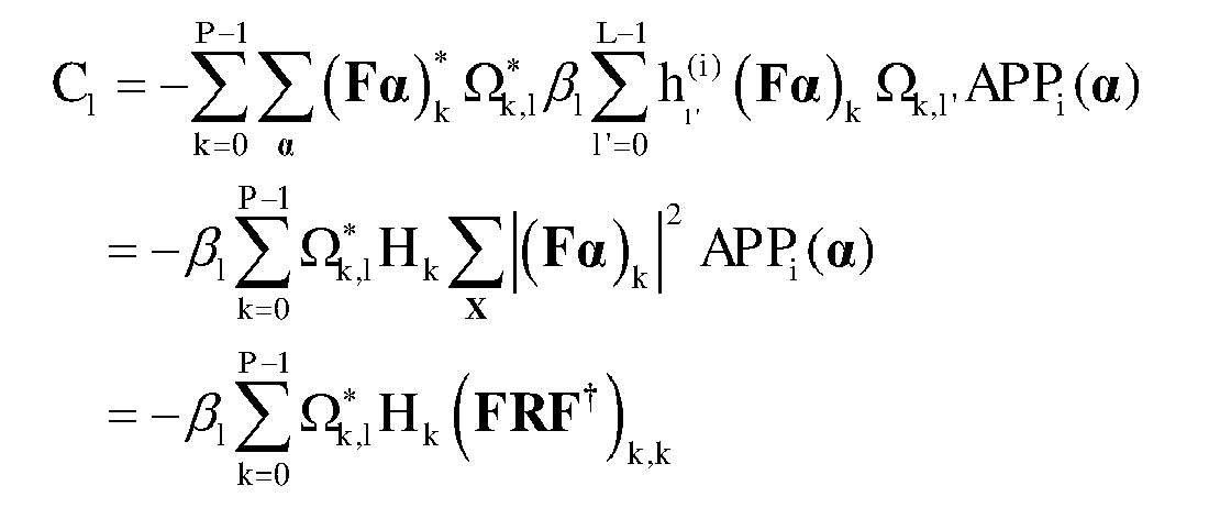

-
Fig. 5 discloses an example of an algorithm executed by a receiver according to a first mode of realization of the present invention. - More precisely, the algorithm is executed by the
processor 200 of the receiver Rec or by thewireless interface 205 of the receiver Rec. - The present algorithm is executed periodically, for example every 71 microseconds or every millisecond.
- During the iterative process, the link between the source Src and the receiver Rec, or in other words the channel impulse response, is determined only from received data symbols.
- At step S500, the non-normalized DFT matrix Ω with size PxL, the DFT matrix F are determined and a variable i is set to null value.
- At next step S501, the received symbols are demodulated in order to produce vector Y. At the same step, cyclic prefix may be removed, a serial to parallel conversion is performed and a demapping is performed.
- At next step S502, an initial estimation of the channel is executed.
- The initial estimation is performed, for instance on pilot symbols, by a usual non-iterative estimation method, such as a least-square (LS) estimation or a minimum mean square channel (MMSE) estimation.
- At next step S503, a demodulation of the SC-FDMA symbols is performed. At that step, an equalization and an inverse DFT are also performed.
- At next step S504, a posteriori probabilities APPi(b) of each coded bit b are determined. The coded bits are disclosed in
Fig. 7 . -
Fig. 7 represents the relationship between coded bits and modulation symbols. The coded bits are grouped into modulation symbols X0..., Xk,...XP-1. - The symbol X0 comprises the bits b0 0 to b0 m-1, the symbol Xk comprises the bits bk 0 to bk m-1 and the symbol XP-1 comprises the bits bP-1 0 to bP-1 m-1 if the modulation scheme under use comprises M=2m symbols.
- For each bit, a posteriori probability that bit b equals one value, i.e. APPi(b=1), and a posteriori probability that bit b equals null value, i.e. APPi(b=0), are determined.
- According to the example of Quadrature Phase-Shift Keying modulation:
- α 0 is represented by bits bk 0 =0 and bk 1=0,
- α 1 is represented by bits bk 0 =0 and bk 1=1,
- α 2 is represented by bits bk 0 =1 and bk 1=1,
- α 3 is represented by bits bk 0 =1 and bk 1=0.
- At next step S505, a posteriori probability APPi(Xk=α1) of each data symbol Xk with k=0 to P-1 is determined.
- The a posteriori probability APPi(Xk=α1) of each data symbol Xk with k=0 to P-1 is determined for each possible modulation symbol value α1 with 1=0 to M-1 from the a posteriori probabilities of coded bits.

- According to the example of Quadrature Phase-Shift Keying modulation:




- At next step S506, the matrix R FX is determined.

- The terms of matrix R are calculated as:


- As R is hermitian:


- At next step S507, diag(FX) is determined.

- The elements X are calculated as:

- At next step S508, the channel impulse response at iteration i+1 is determined.

- At next step S509, the variable i is incremented.
- At next step S510, the variable i is compared to a predetermined value imax which is for example comprised between three and ten.
- The predetermined value imax is for example equal to eight.
- If the variable i is lower than imax, the algorithm returns to step S503 in order to start the following iteration. Otherwise, the algorithm is interrupted.
- The present algorithm is also applicable when pilot symbols are processed at the source by a DFT module in the same way as data symbols.
- In that case, steps S504 and S505 are performed only for the data symbols and the a posteriori probability APPi(Xp) of each pilot symbol Xp is set to the value one for the symbol value equal to the pilot symbol and to the value zero for other symbol values as pilot symbol is known by the receiver Rec.
-
Fig. 6 discloses an example of an algorithm executed by a receiver according to a second mode of realization of the present invention. - More precisely, the algorithm is executed by the
processor 200 of the receiver Rec or by thewireless interface 205 of the receiver Rec. - The present algorithm is executed periodically, for example every 71 microseconds or every millisecond.
- During the iterative process, the link between the source Src and the receiver Rec or in other words the channel impulse response, is determined only from received data symbols.
- At step S600, the non-normalized DFT matrix Ω with size PxL, the DFT matrix F are determined and a variable i is set to null value.
- At next step S601, the received data symbols are demodulated in order to produce vector Y. At the same step, cyclic prefix may be removed, a serial to parallel conversion is performed and a demapping is performed.
- At next step S602, an initial estimation of the channel is executed, for instance on pilot symbols.
- The initial estimation is performed by a usual non-iterative estimation method, such as a least-square (LS) estimation or a minimum mean square channel (MMSE) estimation.
- At next step S603, a demodulation of the SC-FDMA symbols is performed. At that step, an equalization and an inverse DFT are also performed.
- At next step S604, a posteriori probabilities APPi(b) of each coded bit b are determined. The coded bits are disclosed in
Fig. 7 . - For each bit, a posteriori probability that bit b equals one value i.e. APPi(b=1) and a posteriori probability that bit b equals null value, i.e. APPi(b=0), are determined.
- According to the example of Quadrature Phase-Shift Keying modulation:
- α 0 is represented by bits bk 0 =0 and bk 1=0
- α 1 is represented by bits bk 0 =0 and bk 1=1,
- α 2 is represented by bits bk 0 =1 and bk 1=1,
- α 3 is represented by bits bk 0 =1 and bk 1=0.
- At next step S605, a posteriori probability APPi(Xk=α1) of each data symbol Xk with k=0 to P-1 is determined.
- The a posteriori probability APPi(Xk=α1) of each data symbol Xk with k=0 to P-1 is determined for each possible modulation symbol value α1 with 1=0 to M-1 from the a posteriori probabilities of coded bits.

- According to the example of Quadrature Phase-Shift Keying modulation:


- At next step S606, the trace Trace(R Fx) of matrix R FX is determined.
- R FX = diag (diagM (FRF †)) as disclosed at step S506.
- At next step S607, three terms A1, B1, and C1 are determined for each 1=0 to L-1.


- At next step S608, each channel impulse response with 1=0 to L-1 at iteration i+1 is determined.

- The denominator is the trace of RFX .
- The numerator is the sum of three terms A1+B1+C1.
- At next step S609, the variable i is incremented.
- At next step S610, the variable i is compared to a predetermined value imax which is for example comprised between three and ten.
- The predetermined value imax is for example equal to eight.
- If the variable i is lower than imax, the algorithm returns to step S603 in order to start the following iteration. Otherwise, the algorithm is interrupted.
- The present algorithm is also applicable when pilot symbols are processed at the source by a DFT module in the same way as data symbols.
- In that case steps S504 and S505 are performed only for the data symbols and the a posteriori probability APPi(Xp) of each pilot symbol Xp is set to the value one for the symbol value equal to the pilot symbol and to the value zero for other symbol values as pilot symbol is known by the receiver Rec.
-
Fig. 8 discloses an example of an algorithm executed by a receiver according to a third mode of realization of the present invention. - The present algorithm is executed periodically, for example every 71 microseconds or every millisecond.
- The present algorithm differs from the algorithm of
Fig. 5 in the sense that during the iterative process, the link between the source Src and the receiver Rec or in other word the channel impulse response is determined from received pilot symbols and from received data symbols and the pilot symbols are not processed at the source by a DFT module as data symbols and are individually mapped onto subcarriers. - At step S800, the non-normalized DFT matrix Ω with size P=( Nd+ Np) multiplied by L is determined on the Nd subcarriers on which data symbols are mapped and on Np subcarriers on which pilot symbols are mapped, the DFT matrix F is determined with a size Nd x Nd and a variable i is set to null value.
- At next step S801, the received data symbols and pilot symbols are demodulated in order to produce vector Y. At the same step, cyclic prefix may be removed, a serial to parallel conversion is performed and a demapping is performed.
- At
next step S 802, an initial estimation of the channel is executed. - The initial estimation is performed, for instance on pilot symbols, by a usual non-iterative estimation method, such as a least-square (LS) estimation or a minimum mean square channel (MMSE) estimation.
- At next step S803, a demodulation of the SC-FDMA data symbols is performed. At that step, an equalization and an inverse DFT are also performed.
- At next step S804, a posteriori probabilities APPi(b) of each coded bit b are determined. The coded bits are disclosed in
Fig. 7 . - For each bit, a posteriori probability that bit b equals one value, i.e. APPi(b=1), and a posteriori probability that bit b equals null value, i.e. APPi(b=0), are determined.
- According to the example of Quadrature Phase-Shift Keying modulation:
- α 0 is represented by bits bk 0 =0 and bk 1=0
- α 1 is represented by bits bk 0 =0 and bk 1=1,
- α 2 is represented by bits bk 0 =1 and bk 1=1,
- α 3 is represented by bits bk 0 =1 and bk 1=0.
- At next step S805, a posteriori probability APPi(Xk=α1) of each data symbol Xk with k=0 to Nd-1 is determined.
- The a posteriori probability APPi(Xk=α1) of each data symbol Xk with k=0 to Nd-1 is determined for each possible modulation symbol value α1 with 1=0 to M-1 from the a posteriori probabilities of coded bits.

- According to the example of Quadrature Phase-Shift Keying modulation:


- At next step S806, the matrix R FX is determined.

- The terms of matrix R are calculated as:


- At next step S807, a new matrix is formed. The new matrix R x' comprises the matrix RFX and new lines at positions of subcarriers on which pilot symbols are mapped. For each received pilot symbol Xp, the energy value |Xp|2 of the received pilot symbol Xp is inserted in the line at element position corresponding to the diagonal of the new matrix RX' .
- At next step S808, diag(FX) is determined as disclosed as step S507.
- At next step S809, a new diagonal matrix diag(X')is formed. diag(X') takes values of diag(FX) on lines on which data symbols are mapped and pilot symbols Xp on lines on which pilot symbols are mapped.
- At next step S810, the channel impulse response at iteration i+1 is determined.

- At
next step S 811, the variable i is incremented. - At next step S812, the variable i is compared to a predetermined value imax which is for example comprised between three and ten.
- The predetermined value imax is for example equal to eight.
- If the variable i is lower than imax, the algorithm returns to step S803 in order to start the following iteration. Otherwise, the algorithm is interrupted.
-
Fig. 9 discloses an example of an algorithm executed by a receiver according to a fourth mode of realization of the present invention. - The present algorithm is executed periodically, for example every 71 microseconds or every millisecond.
- The present algorithm differs from the algorithm of
Fig. 6 in the sense that during the iterative process, the link between the source Src and the receiver Rec or in other words the channel impulse response is determined from received pilot symbols and from received data symbols and the pilot symbols are not processed at the source by a DFT module as data symbols and are individually mapped onto subcarriers. - At step S900, the non-normalized DFT matrix Ω with size PxL is determined on the Nd subcarriers on which data are mapped and on Np subcarriers on which pilot symbols are mapped, the DFT matrix F is determined with size Nd x Nd and a variable i is set to null value.
- At next step S901, the received data symbols and pilot symbols are demodulated in order to produce vector Y. At the same step, cyclic prefix may be removed, a serial to parallel conversion is performed and a demapping is performed.
- At next step S902, an initial estimation of the channel is executed.
- The initial estimation is performed, for instance on pilot symbols, by a usual non-iterative estimation method, such as a least-square (LS) estimation or a minimum mean square channel estimation.
- At next step S903, a demodulation of the SC-FDMA symbols is performed. At that step, an equalization and an inverse DFT are also performed.
- At next step S904, a posteriori probabilities APPi(b) of each coded bit b are determined. The coded bits are disclosed in
Fig. 7 . - For each bit, a posteriori probability that bit b equals one value, i.e. APPi(b=1), and a posteriori probability that bit b equals null value, i.e. APPi(b=0), are determined.
- According to the example of Quadrature Phase-Shift Keying modulation:
- α 0 is represented by bits bk 0 =0 and bk 1=0
- α 1 is represented by bits bk 0 =0 and bk 1=1,
- α 2 is represented by bits bk 0 =1 and bk 1=1,
- α 3 is represented by bits bk 0 =1 and bk 1=0.
- At next step S905, a posteriori probability APPi(Xk=α1) of each data symbol Xk with k=0 to Nd-1 is determined.
- The a posteriori probability APPi(Xk=α1) of each data symbol Xk with k=0 to Nd-1 is determined for each possible modulation symbol value α1 with 1=0 to M-1 from the a posteriori probabilities of coded bits.

- According to the example of Quadrature Phase-Shift Keying modulation:


- At next step S906, the trace of matrix RFX is determined.

- At next step S907, three terms A1', B1', and C1' are determined.


- where kd(m) is the subcarrier of which the m-th data symbol is mapped and kp(j) is the subcarrier of which the j-th pilot symbol is mapped.
- At next step S908, each channel impulse response with 1=0 to L-1 at iteration i+1 is determined:

- The denominator is the trace of RFX plus the sum of the energies of the received pilot symbols.
- The numerator is the sum of three terms A1'+B1'+C1'.
- At next step S909, the variable i is incremented.
- At next step S910, the variable i is compared to a predetermined value imax which is for example comprised between three and ten.
- The predetermined value imax is for example equal to eight.
- If the variable i is lower than imax, the algorithm returns to step S903 in order to start the following iteration. Otherwise, the algorithm is interrupted.
- Naturally, many modifications can be made to the embodiments of the invention described above without departing from the scope of the present invention.
Claims (15)
- Method for estimating a channel impulse response between a source and a receiver, data transmitted by the source being coded and organized as data symbols, data symbols being converted from serial to parallel and spread in the frequency domain by a Discrete Fourier Transform, the data symbols spread in the frequency domain being mapped on P sub-carriers allocated for transmission among N sub-carriers of a frequency band, transformed back in the time domain by an Inverse Discrete Fourier Transform module, parallel to serial converted and transferred to the receiver under the form of signals representative of data symbols, characterized in that the method comprises the steps, executed by the receiver of:- determining a first matrix with size PxL, L being the number of taps assumed in the channel impulse response and determining a Discrete Fourier Transform matrix of size PxP,- demodulating the received signals representative of data symbols, in order to produce received data symbols,- parallelizing the received data symbols,- executing a Discrete Fourier Transform on the parallelized received data symbols,- demapping the transformed received data symbols from the sub-carriers,- estimating iteratively the channel impulse response from the demapped received data symbols, the channel estimation being dependent of the first matrix, the Discrete Fourier Transform matrix and of a second matrix which is defined according to a posteriori probabilities that the transferred data symbols are equal to possible modulation symbols of the modulation scheme.
- Method according to claim 1, characterised in that the second matrix is a diagonal matrix, the elements of which being diagonal elements of a third matrix obtained from the Discrete Fourier Transform matrix and from a fourth matrix, the elements of the fourth matrix being equal to:

and
for 1 ≠ j
where APPi(Xk=α1) is the a posteriori probability that data symbol Xk is equal to α1, α1 is the 1-th modulation symbol of the possible modulation symbols, M is the total number of possible modulation symbols and (.)* denotes the conjugate of (.). - Method according to claim 2, characterised in that the second matrix is equal to :
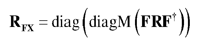
where diag(.) denotes a diagonal matrix, in which vector (.) is the diagonal, diagM(.) denotes a vector made of the elements of the diagonal of the matrix (.), F is the Discrete Fourier Transform matrix and (.)† denotes the transpose conjugate of (.) - Method according to claim 3, characterised in that the channel impulse response at the (i+1)-th iteration is determined according to the following formula:

where Ω is a matrix with size PxL, built from the L first columns of a non-normalized DFT matrix Ω N with size NxN and the P rows of the matrix Ω N corresponding to allocated subcarriers, diag(.) denotes a diagonal matrix, in which vector (.) is the diagonal, F is the Discrete Fourier Transform, (.)†denotes the transpose conjugate of (.),R FX is the second matrix and Y is a size-P vector of demapped received data symbols, X being determined from a posteriori probabilities that symbol Xk equals α1,α1 being the 1-th modulation symbol of the possible modulation symbols. - Method according to claim 2, characterised in that only the diagonal coefficients of the third matrix are calculated.
- Method according to any of the claims 1 to 5, characterised in that the source further transfers pilot symbols spread in the frequency domain by the Discrete Fourier Transform and the receiver sets the a posteriori probability of each pilot symbol to the value one for the symbol value equal to the pilot symbol and to the value zero for other symbol values.
- Method according to any of the claims 1 to 5, characterised in that the source further transfers pilot symbols not spread in the frequency domain by the Discrete Fourier Transform and in that the method comprises further steps of :- enlarging the second matrix into a new matrix by inserting new lines at positions of subcarriers on which pilot symbols are mapped,- inserting, for each received pilot symbol, the energy value of the received pilot symbol in the line at element position corresponding to the diagonal of the new matrix.
- Method according to claim 1, characterised in that the channel estimation is dependent of the second matrix as being calculated from the trace of the second matrix.
- Method according to claims 3 and 8, characterised in that the denominator of the channel impulse response at the (i+1)-th iteration is the trace of R FX = diag (diagM (FRF† )).
- Method according to claims 8 and 2, characterised in that the channel impulse response at the (i+1)-th iteration is determined according to the following formula:

where A1, B1, and C1 are determined for each 1=0 to L-1, h1 (i) is the 1-th tap of the
channel impulse response at the i-th iteration, A1 = h1 (i)Trace(RFX )

Ω k,l' is the coefficient at k-th row and /'-the column of the first matrix Ω, Yk is the k-th coefficient of a size P vector of demapped received data symbols,
(.)† denotes the transpose conjugate of (.) and (.)* denotes the conjugate of (.) - Method according to claims 8 to 10, characterised in that the source further transfers pilot symbols spread in the frequency domain by the Discrete Fourier Transform and the receiver sets the a posteriori probability of each pilot symbol to the value one for the symbol value equal to the pilot symbol and to the value zero for other symbol values.
- Method according to claims 8 to 10, characterised in that the source further transfers pilot symbols not spread in the frequency domain by the Discrete Fourier Transform and in that the channel impulse response is further dependent of the sum of the energies of the pilot symbols.
- Method according to any of the claims 1 to 12, characterised in that the channel impulse response is estimated iteratively a predetermined number of times.
- Device for estimating a channel impulse response between a source and a receiver, data transmitted by the source being coded and organized as data symbols, symbols being converted from serial to parallel and spread in the frequency domain by a Discrete Fourier Transform, the data symbols spread in the frequency domain being mapped on P sub-carriers allocated for transmission among N sub-carriers of a frequency band, transformed back in the time domain by an Inverse Discrete Fourier Transform module, parallel to serial converted and transferred to the receiver under the form of signals representative of data symbols, characterized in that the device is included in the receiver and comprises:- means for determining a first matrix with size PxL, L being the number of taps assumed in the channel impulse response and determining a Discrete Fourier Transform matrix of size PxP ,- means for demodulating the received signals representative of data symbols, in order to produce received data symbols,- means for parallelizing the received data symbols,- means for executing a Discrete Fourier Transform on the parallelized received data symbols,- means for demapping the transformed received data symbols from sub-carriers,- means for estimating iteratively the channel impulse response from the demapped received data symbols, the channel estimation being dependent of the first matrix, the Discrete Fourier Transform matrix and of a second matrix which is defined according to a posteriori probabilities that the transferred data symbols are equal to possible modulation symbols of the modulation scheme.
- Computer program which can be directly loadable into a programmable device, comprising instructions or portions of code for implementing the steps of the method according to claims 1 to 13 when said computer program is executed on a programmable device.
Priority Applications (2)
| Application Number | Priority Date | Filing Date | Title |
|---|---|---|---|
| EP11190302.7A EP2597833B1 (en) | 2011-11-23 | 2011-11-23 | Method and a device for estimating a link between a source and a receiver using SC-FDMA |
| JP2012255894A JP6110641B2 (en) | 2011-11-23 | 2012-11-22 | Method and device for estimating channel impulse response between source and receiver |
Applications Claiming Priority (1)
| Application Number | Priority Date | Filing Date | Title |
|---|---|---|---|
| EP11190302.7A EP2597833B1 (en) | 2011-11-23 | 2011-11-23 | Method and a device for estimating a link between a source and a receiver using SC-FDMA |
Publications (2)
| Publication Number | Publication Date |
|---|---|
| EP2597833A1 true EP2597833A1 (en) | 2013-05-29 |
| EP2597833B1 EP2597833B1 (en) | 2017-05-17 |
Family
ID=45033857
Family Applications (1)
| Application Number | Title | Priority Date | Filing Date |
|---|---|---|---|
| EP11190302.7A Not-in-force EP2597833B1 (en) | 2011-11-23 | 2011-11-23 | Method and a device for estimating a link between a source and a receiver using SC-FDMA |
Country Status (2)
| Country | Link |
|---|---|
| EP (1) | EP2597833B1 (en) |
| JP (1) | JP6110641B2 (en) |
Cited By (2)
| Publication number | Priority date | Publication date | Assignee | Title |
|---|---|---|---|---|
| US10182439B2 (en) | 2016-02-16 | 2019-01-15 | Samsung Electronics Co., Ltd | Method and apparatus for data-aided iterative channel estimation |
| CN113572708A (en) * | 2021-06-30 | 2021-10-29 | 西安电子科技大学 | An Improved Method for DFT Channel Estimation |
Families Citing this family (1)
| Publication number | Priority date | Publication date | Assignee | Title |
|---|---|---|---|---|
| KR101603313B1 (en) * | 2014-07-26 | 2016-03-15 | 주식회사 텔레칩스 | Channel estimation method for OFDM receivers, and computer-readable recording medium for the same |
Family Cites Families (2)
| Publication number | Priority date | Publication date | Assignee | Title |
|---|---|---|---|---|
| US7092436B2 (en) * | 2002-01-25 | 2006-08-15 | Mitsubishi Electric Research Laboratories, Inc. | Expectation-maximization-based channel estimation and signal detection for wireless communications systems |
| EP2144413B1 (en) * | 2008-07-11 | 2014-10-01 | Mitsubishi Electric R&D Centre Europe B.V. | Iterative channel estimation and decoding using belief propagation with Gaussian approximation |
-
2011
- 2011-11-23 EP EP11190302.7A patent/EP2597833B1/en not_active Not-in-force
-
2012
- 2012-11-22 JP JP2012255894A patent/JP6110641B2/en not_active Expired - Fee Related
Non-Patent Citations (4)
| Title |
|---|
| THE-HANH PHAM ET AL: "A joint channel estimation and data detection receiver for multiuser MIMO IFDMA systems", IEEE TRANSACTIONS ON COMMUNICATIONS, IEEE SERVICE CENTER, PISCATAWAY, NJ. USA, vol. 57, no. 6, 1 June 2009 (2009-06-01), pages 1857 - 1865, XP011262839, ISSN: 0090-6778, DOI: 10.1109/TCOMM.2009.06.070555 * |
| XINGZHONG XIONG ET AL: "Effect of channel estimation error on the performance of Interleave-Division Multiple Access systems", ADVANCED COMMUNICATION TECHNOLOGY, 2009. ICACT 2009. 11TH INTERNATIONAL CONFERENCE ON, GIRI, PISCATAWAY, NJ, USA, 15 February 2009 (2009-02-15), pages 1538 - 1542, XP031445666, ISBN: 978-89-5519-138-7 * |
| YANG LIU ET AL: "EM-Based Channel Estimation for Coded Multi-Carrier Transmissions", IEEE TRANSACTIONS ON WIRELESS COMMUNICATIONS, IEEE SERVICE CENTER, PISCATAWAY, NJ, US, vol. 10, no. 10, 1 October 2011 (2011-10-01), pages 3185 - 3195, XP011389657, ISSN: 1536-1276, DOI: 10.1109/TWC.2011.080311.100249 * |
| YANG LIU ET AL: "Simplified EM channel estimation in LTE systems", ACOUSTICS, SPEECH AND SIGNAL PROCESSING (ICASSP), 2011 IEEE INTERNATIONAL CONFERENCE ON, IEEE, 22 May 2011 (2011-05-22), pages 3480 - 3483, XP032000563, ISBN: 978-1-4577-0538-0, DOI: 10.1109/ICASSP.2011.5946227 * |
Cited By (3)
| Publication number | Priority date | Publication date | Assignee | Title |
|---|---|---|---|---|
| US10182439B2 (en) | 2016-02-16 | 2019-01-15 | Samsung Electronics Co., Ltd | Method and apparatus for data-aided iterative channel estimation |
| CN113572708A (en) * | 2021-06-30 | 2021-10-29 | 西安电子科技大学 | An Improved Method for DFT Channel Estimation |
| CN113572708B (en) * | 2021-06-30 | 2023-03-14 | 西安电子科技大学 | DFT channel estimation improvement method |
Also Published As
| Publication number | Publication date |
|---|---|
| JP6110641B2 (en) | 2017-04-05 |
| JP2013110745A (en) | 2013-06-06 |
| EP2597833B1 (en) | 2017-05-17 |
Similar Documents
| Publication | Publication Date | Title |
|---|---|---|
| EP1949632B1 (en) | Methods and apparatus for mitigation of nonlinear distortion | |
| US8081690B2 (en) | OFDM channel estimation | |
| US8548101B2 (en) | Demodulation method and demodulator for orthogonal frequency multiplexing—multiple input multiple output system | |
| US8654879B2 (en) | Multi-antenna channel estimation method based on polyphase decomposition | |
| US8223862B2 (en) | OFDM inter-carrier interference cancellation method | |
| CN103873397B (en) | A kind of new joint time domain and frequency domain OFDM receive channel estimation methods | |
| US7945005B2 (en) | Method and module for estimating transmission chanels of a multi-antenna multi-carrier system | |
| CN101601243A (en) | OFDM channel estimation | |
| US20100311343A1 (en) | Hierarchical modulation for accurate channel sounding | |
| Gorbunov et al. | BER performance of SEFDM signals in LTE fading channels | |
| EP1901505A2 (en) | Wireless communication apparatus | |
| US20040165683A1 (en) | Channel estimation for communication systems | |
| EP2597833B1 (en) | Method and a device for estimating a link between a source and a receiver using SC-FDMA | |
| EP2356768B1 (en) | Symbol level layer shifting for multiple stream transmission using dft-spread ofdm | |
| EP1914919A1 (en) | Receiver apparatus | |
| JPWO2007020943A1 (en) | OFDM communication method | |
| US20110019696A1 (en) | Mmse method and system | |
| JP5986355B2 (en) | Method and device for transferring data and information to enable estimation of a radio link between a source and at least one receiver using single carrier orthogonal frequency division multiplexing, and single carrier orthogonal frequency division multiplexing Method and device for estimating a radio link between a source and a receiver using a scheme | |
| CN101132381B (en) | Channel Estimation Method for Pilot Data Transmission in MIMO-OFDM System | |
| Huemer et al. | Unique word prefix in SC/FDE and OFDM: A comparison | |
| Galih et al. | High mobility data pilot based channel estimation for downlink OFDMA system based on IEEE 802.16 e standard | |
| Fang et al. | Iterative channel estimation and turbo equalization for time-varying OFDM systems | |
| Wang et al. | A novel equalization scheme for ZP-OFDM system over deep fading channels | |
| EP3566326B1 (en) | Method and device for improving channel estimation in a multi-user mimo-ofdm system | |
| WO2017097077A1 (en) | Data processing method and apparatus |
Legal Events
| Date | Code | Title | Description |
|---|---|---|---|
| PUAI | Public reference made under article 153(3) epc to a published international application that has entered the european phase |
Free format text: ORIGINAL CODE: 0009012 |
|
| AK | Designated contracting states |
Kind code of ref document: A1 Designated state(s): AL AT BE BG CH CY CZ DE DK EE ES FI FR GB GR HR HU IE IS IT LI LT LU LV MC MK MT NL NO PL PT RO RS SE SI SK SM TR |
|
| AX | Request for extension of the european patent |
Extension state: BA ME |
|
| 17P | Request for examination filed |
Effective date: 20131122 |
|
| RBV | Designated contracting states (corrected) |
Designated state(s): AL AT BE BG CH CY CZ DE DK EE ES FI FR GB GR HR HU IE IS IT LI LT LU LV MC MK MT NL NO PL PT RO RS SE SI SK SM TR |
|
| 17Q | First examination report despatched |
Effective date: 20140317 |
|
| GRAP | Despatch of communication of intention to grant a patent |
Free format text: ORIGINAL CODE: EPIDOSNIGR1 |
|
| INTG | Intention to grant announced |
Effective date: 20161202 |
|
| GRAS | Grant fee paid |
Free format text: ORIGINAL CODE: EPIDOSNIGR3 |
|
| GRAA | (expected) grant |
Free format text: ORIGINAL CODE: 0009210 |
|
| AK | Designated contracting states |
Kind code of ref document: B1 Designated state(s): AL AT BE BG CH CY CZ DE DK EE ES FI FR GB GR HR HU IE IS IT LI LT LU LV MC MK MT NL NO PL PT RO RS SE SI SK SM TR |
|
| REG | Reference to a national code |
Ref country code: GB Ref legal event code: FG4D |
|
| REG | Reference to a national code |
Ref country code: CH Ref legal event code: EP |
|
| REG | Reference to a national code |
Ref country code: IE Ref legal event code: FG4D |
|
| REG | Reference to a national code |
Ref country code: AT Ref legal event code: REF Ref document number: 895370 Country of ref document: AT Kind code of ref document: T Effective date: 20170615 |
|
| REG | Reference to a national code |
Ref country code: DE Ref legal event code: R096 Ref document number: 602011037991 Country of ref document: DE |
|
| REG | Reference to a national code |
Ref country code: NL Ref legal event code: MP Effective date: 20170517 |
|
| REG | Reference to a national code |
Ref country code: LT Ref legal event code: MG4D |
|
| REG | Reference to a national code |
Ref country code: AT Ref legal event code: MK05 Ref document number: 895370 Country of ref document: AT Kind code of ref document: T Effective date: 20170517 |
|
| PG25 | Lapsed in a contracting state [announced via postgrant information from national office to epo] |
Ref country code: LT Free format text: LAPSE BECAUSE OF FAILURE TO SUBMIT A TRANSLATION OF THE DESCRIPTION OR TO PAY THE FEE WITHIN THE PRESCRIBED TIME-LIMIT Effective date: 20170517 Ref country code: ES Free format text: LAPSE BECAUSE OF FAILURE TO SUBMIT A TRANSLATION OF THE DESCRIPTION OR TO PAY THE FEE WITHIN THE PRESCRIBED TIME-LIMIT Effective date: 20170517 Ref country code: HR Free format text: LAPSE BECAUSE OF FAILURE TO SUBMIT A TRANSLATION OF THE DESCRIPTION OR TO PAY THE FEE WITHIN THE PRESCRIBED TIME-LIMIT Effective date: 20170517 Ref country code: FI Free format text: LAPSE BECAUSE OF FAILURE TO SUBMIT A TRANSLATION OF THE DESCRIPTION OR TO PAY THE FEE WITHIN THE PRESCRIBED TIME-LIMIT Effective date: 20170517 Ref country code: AT Free format text: LAPSE BECAUSE OF FAILURE TO SUBMIT A TRANSLATION OF THE DESCRIPTION OR TO PAY THE FEE WITHIN THE PRESCRIBED TIME-LIMIT Effective date: 20170517 Ref country code: GR Free format text: LAPSE BECAUSE OF FAILURE TO SUBMIT A TRANSLATION OF THE DESCRIPTION OR TO PAY THE FEE WITHIN THE PRESCRIBED TIME-LIMIT Effective date: 20170818 Ref country code: NO Free format text: LAPSE BECAUSE OF FAILURE TO SUBMIT A TRANSLATION OF THE DESCRIPTION OR TO PAY THE FEE WITHIN THE PRESCRIBED TIME-LIMIT Effective date: 20170817 |
|
| REG | Reference to a national code |
Ref country code: FR Ref legal event code: PLFP Year of fee payment: 7 |
|
| PG25 | Lapsed in a contracting state [announced via postgrant information from national office to epo] |
Ref country code: RS Free format text: LAPSE BECAUSE OF FAILURE TO SUBMIT A TRANSLATION OF THE DESCRIPTION OR TO PAY THE FEE WITHIN THE PRESCRIBED TIME-LIMIT Effective date: 20170517 Ref country code: LV Free format text: LAPSE BECAUSE OF FAILURE TO SUBMIT A TRANSLATION OF THE DESCRIPTION OR TO PAY THE FEE WITHIN THE PRESCRIBED TIME-LIMIT Effective date: 20170517 Ref country code: PL Free format text: LAPSE BECAUSE OF FAILURE TO SUBMIT A TRANSLATION OF THE DESCRIPTION OR TO PAY THE FEE WITHIN THE PRESCRIBED TIME-LIMIT Effective date: 20170517 Ref country code: IS Free format text: LAPSE BECAUSE OF FAILURE TO SUBMIT A TRANSLATION OF THE DESCRIPTION OR TO PAY THE FEE WITHIN THE PRESCRIBED TIME-LIMIT Effective date: 20170917 Ref country code: SE Free format text: LAPSE BECAUSE OF FAILURE TO SUBMIT A TRANSLATION OF THE DESCRIPTION OR TO PAY THE FEE WITHIN THE PRESCRIBED TIME-LIMIT Effective date: 20170517 Ref country code: BG Free format text: LAPSE BECAUSE OF FAILURE TO SUBMIT A TRANSLATION OF THE DESCRIPTION OR TO PAY THE FEE WITHIN THE PRESCRIBED TIME-LIMIT Effective date: 20170817 Ref country code: NL Free format text: LAPSE BECAUSE OF FAILURE TO SUBMIT A TRANSLATION OF THE DESCRIPTION OR TO PAY THE FEE WITHIN THE PRESCRIBED TIME-LIMIT Effective date: 20170517 |
|
| PG25 | Lapsed in a contracting state [announced via postgrant information from national office to epo] |
Ref country code: SK Free format text: LAPSE BECAUSE OF FAILURE TO SUBMIT A TRANSLATION OF THE DESCRIPTION OR TO PAY THE FEE WITHIN THE PRESCRIBED TIME-LIMIT Effective date: 20170517 Ref country code: CZ Free format text: LAPSE BECAUSE OF FAILURE TO SUBMIT A TRANSLATION OF THE DESCRIPTION OR TO PAY THE FEE WITHIN THE PRESCRIBED TIME-LIMIT Effective date: 20170517 Ref country code: DK Free format text: LAPSE BECAUSE OF FAILURE TO SUBMIT A TRANSLATION OF THE DESCRIPTION OR TO PAY THE FEE WITHIN THE PRESCRIBED TIME-LIMIT Effective date: 20170517 Ref country code: RO Free format text: LAPSE BECAUSE OF FAILURE TO SUBMIT A TRANSLATION OF THE DESCRIPTION OR TO PAY THE FEE WITHIN THE PRESCRIBED TIME-LIMIT Effective date: 20170517 Ref country code: EE Free format text: LAPSE BECAUSE OF FAILURE TO SUBMIT A TRANSLATION OF THE DESCRIPTION OR TO PAY THE FEE WITHIN THE PRESCRIBED TIME-LIMIT Effective date: 20170517 |
|
| REG | Reference to a national code |
Ref country code: DE Ref legal event code: R097 Ref document number: 602011037991 Country of ref document: DE |
|
| PG25 | Lapsed in a contracting state [announced via postgrant information from national office to epo] |
Ref country code: IT Free format text: LAPSE BECAUSE OF FAILURE TO SUBMIT A TRANSLATION OF THE DESCRIPTION OR TO PAY THE FEE WITHIN THE PRESCRIBED TIME-LIMIT Effective date: 20170517 Ref country code: SM Free format text: LAPSE BECAUSE OF FAILURE TO SUBMIT A TRANSLATION OF THE DESCRIPTION OR TO PAY THE FEE WITHIN THE PRESCRIBED TIME-LIMIT Effective date: 20170517 |
|
| PLBE | No opposition filed within time limit |
Free format text: ORIGINAL CODE: 0009261 |
|
| STAA | Information on the status of an ep patent application or granted ep patent |
Free format text: STATUS: NO OPPOSITION FILED WITHIN TIME LIMIT |
|
| 26N | No opposition filed |
Effective date: 20180220 |
|
| PG25 | Lapsed in a contracting state [announced via postgrant information from national office to epo] |
Ref country code: SI Free format text: LAPSE BECAUSE OF FAILURE TO SUBMIT A TRANSLATION OF THE DESCRIPTION OR TO PAY THE FEE WITHIN THE PRESCRIBED TIME-LIMIT Effective date: 20170517 |
|
| PG25 | Lapsed in a contracting state [announced via postgrant information from national office to epo] |
Ref country code: MC Free format text: LAPSE BECAUSE OF FAILURE TO SUBMIT A TRANSLATION OF THE DESCRIPTION OR TO PAY THE FEE WITHIN THE PRESCRIBED TIME-LIMIT Effective date: 20170517 |
|
| PG25 | Lapsed in a contracting state [announced via postgrant information from national office to epo] |
Ref country code: CH Free format text: LAPSE BECAUSE OF NON-PAYMENT OF DUE FEES Effective date: 20171130 Ref country code: LI Free format text: LAPSE BECAUSE OF NON-PAYMENT OF DUE FEES Effective date: 20171130 |
|
| PG25 | Lapsed in a contracting state [announced via postgrant information from national office to epo] |
Ref country code: LU Free format text: LAPSE BECAUSE OF NON-PAYMENT OF DUE FEES Effective date: 20171123 |
|
| REG | Reference to a national code |
Ref country code: BE Ref legal event code: MM Effective date: 20171130 |
|
| REG | Reference to a national code |
Ref country code: IE Ref legal event code: MM4A |
|
| PG25 | Lapsed in a contracting state [announced via postgrant information from national office to epo] |
Ref country code: MT Free format text: LAPSE BECAUSE OF NON-PAYMENT OF DUE FEES Effective date: 20171123 |
|
| REG | Reference to a national code |
Ref country code: FR Ref legal event code: PLFP Year of fee payment: 8 |
|
| PG25 | Lapsed in a contracting state [announced via postgrant information from national office to epo] |
Ref country code: IE Free format text: LAPSE BECAUSE OF NON-PAYMENT OF DUE FEES Effective date: 20171123 |
|
| PG25 | Lapsed in a contracting state [announced via postgrant information from national office to epo] |
Ref country code: BE Free format text: LAPSE BECAUSE OF NON-PAYMENT OF DUE FEES Effective date: 20171130 |
|
| PG25 | Lapsed in a contracting state [announced via postgrant information from national office to epo] |
Ref country code: HU Free format text: LAPSE BECAUSE OF FAILURE TO SUBMIT A TRANSLATION OF THE DESCRIPTION OR TO PAY THE FEE WITHIN THE PRESCRIBED TIME-LIMIT; INVALID AB INITIO Effective date: 20111123 |
|
| PG25 | Lapsed in a contracting state [announced via postgrant information from national office to epo] |
Ref country code: CY Free format text: LAPSE BECAUSE OF NON-PAYMENT OF DUE FEES Effective date: 20170517 |
|
| PG25 | Lapsed in a contracting state [announced via postgrant information from national office to epo] |
Ref country code: MK Free format text: LAPSE BECAUSE OF FAILURE TO SUBMIT A TRANSLATION OF THE DESCRIPTION OR TO PAY THE FEE WITHIN THE PRESCRIBED TIME-LIMIT Effective date: 20170517 |
|
| PG25 | Lapsed in a contracting state [announced via postgrant information from national office to epo] |
Ref country code: TR Free format text: LAPSE BECAUSE OF FAILURE TO SUBMIT A TRANSLATION OF THE DESCRIPTION OR TO PAY THE FEE WITHIN THE PRESCRIBED TIME-LIMIT Effective date: 20170517 |
|
| PG25 | Lapsed in a contracting state [announced via postgrant information from national office to epo] |
Ref country code: PT Free format text: LAPSE BECAUSE OF FAILURE TO SUBMIT A TRANSLATION OF THE DESCRIPTION OR TO PAY THE FEE WITHIN THE PRESCRIBED TIME-LIMIT Effective date: 20170517 |
|
| PG25 | Lapsed in a contracting state [announced via postgrant information from national office to epo] |
Ref country code: AL Free format text: LAPSE BECAUSE OF FAILURE TO SUBMIT A TRANSLATION OF THE DESCRIPTION OR TO PAY THE FEE WITHIN THE PRESCRIBED TIME-LIMIT Effective date: 20170517 |
|
| REG | Reference to a national code |
Ref country code: GB Ref legal event code: 746 Effective date: 20200824 |
|
| REG | Reference to a national code |
Ref country code: DE Ref legal event code: R084 Ref document number: 602011037991 Country of ref document: DE |
|
| PGFP | Annual fee paid to national office [announced via postgrant information from national office to epo] |
Ref country code: GB Payment date: 20210930 Year of fee payment: 11 |
|
| PGFP | Annual fee paid to national office [announced via postgrant information from national office to epo] |
Ref country code: DE Payment date: 20210929 Year of fee payment: 11 Ref country code: FR Payment date: 20211109 Year of fee payment: 11 |
|
| REG | Reference to a national code |
Ref country code: DE Ref legal event code: R119 Ref document number: 602011037991 Country of ref document: DE |
|
| GBPC | Gb: european patent ceased through non-payment of renewal fee |
Effective date: 20221123 |
|
| PG25 | Lapsed in a contracting state [announced via postgrant information from national office to epo] |
Ref country code: GB Free format text: LAPSE BECAUSE OF NON-PAYMENT OF DUE FEES Effective date: 20221123 Ref country code: DE Free format text: LAPSE BECAUSE OF NON-PAYMENT OF DUE FEES Effective date: 20230601 |
|
| PG25 | Lapsed in a contracting state [announced via postgrant information from national office to epo] |
Ref country code: FR Free format text: LAPSE BECAUSE OF NON-PAYMENT OF DUE FEES Effective date: 20221130 |