EP2356768B1 - Symbol level layer shifting for multiple stream transmission using dft-spread ofdm - Google Patents
Symbol level layer shifting for multiple stream transmission using dft-spread ofdm Download PDFInfo
- Publication number
- EP2356768B1 EP2356768B1 EP09756794.5A EP09756794A EP2356768B1 EP 2356768 B1 EP2356768 B1 EP 2356768B1 EP 09756794 A EP09756794 A EP 09756794A EP 2356768 B1 EP2356768 B1 EP 2356768B1
- Authority
- EP
- European Patent Office
- Prior art keywords
- dfts
- layer
- symbol
- layers
- stream transmission
- Prior art date
- Legal status (The legal status is an assumption and is not a legal conclusion. Google has not performed a legal analysis and makes no representation as to the accuracy of the status listed.)
- Active
Links
Images


Classifications
-
- H—ELECTRICITY
- H04—ELECTRIC COMMUNICATION TECHNIQUE
- H04L—TRANSMISSION OF DIGITAL INFORMATION, e.g. TELEGRAPHIC COMMUNICATION
- H04L5/00—Arrangements affording multiple use of the transmission path
- H04L5/0001—Arrangements for dividing the transmission path
- H04L5/0014—Three-dimensional division
- H04L5/0023—Time-frequency-space
-
- H—ELECTRICITY
- H04—ELECTRIC COMMUNICATION TECHNIQUE
- H04L—TRANSMISSION OF DIGITAL INFORMATION, e.g. TELEGRAPHIC COMMUNICATION
- H04L27/00—Modulated-carrier systems
- H04L27/26—Systems using multi-frequency codes
- H04L27/2601—Multicarrier modulation systems
- H04L27/2626—Arrangements specific to the transmitter only
- H04L27/2627—Modulators
- H04L27/2634—Inverse fast Fourier transform [IFFT] or inverse discrete Fourier transform [IDFT] modulators in combination with other circuits for modulation
- H04L27/2636—Inverse fast Fourier transform [IFFT] or inverse discrete Fourier transform [IDFT] modulators in combination with other circuits for modulation with FFT or DFT modulators, e.g. standard single-carrier frequency-division multiple access [SC-FDMA] transmitter or DFT spread orthogonal frequency division multiplexing [DFT-SOFDM]
Definitions
- the present invention relates to communications networks. More particularly, and not by way of limitation, the present invention is directed to a system and method of single-carrier layer shifting for multiple-stream transmission facilitating Successive Interference Cancellation (SIC) implementation.
- SIC Successive Interference Cancellation
- MIMO Multiple Input Multiple Output
- Each stream is called a layer and corresponds to a sequence of modulation symbols.
- the layers are either directly mapped to the antenna ports or may first undergo a transformation by means of channel dependent or channel independent pre-coding.
- the multiple streams come from single/multiple code words.
- the code words should be mapped into multiple streams in a proper way. If multiple streams experience different channel quality, it is often beneficial to shift the layer mapped from a specific code word by a certain amount, which effectively transmits each code word across multiple layers. This layer shifting helps achieve diversity gain which leads to improved error performance.
- the layer shifting is generally performed in a per-sample basis to maximize diversity gain. Thus, the layer or layers mapped from a code word are shifted for every sample (i.e., every modulation symbol).
- SIC Zero Forcing
- MMSE Minimum Mean Square Error
- FIG. 1 is a simplified block diagram of components of an existing DFTS-OFDM system.
- the system includes a modulator 10, a DFT precoder 12, an Inverse Discrete Fourier Transform (IDFT) 14, and a cyclic prefix adder 16 for processing a signal 18.
- DFTS Discrete Fourier Transform Spread
- OFDM Orthogonal Frequency Division Multiplexing
- the information block is coded and passed through the modulator 10 to produce information carrying symbols that are subsequently transformed to the frequency domain by means of the Discrete Fourier Transform (DFT) precoder.
- the output of the DFT precoder is connected to potentially only a subset of the inputs of the IDFT 14, producing a time domain signal corresponding to one DFTS-OFDM symbol.
- a cyclic prefix is added (at the cyclic prefix adder 16) to the time domain signal which is thereafter transmitted over the channel. This enables transmissions over only a part of the system bandwidth while simplifying channel equalization in the receiver by utilizing an efficient support of frequency domain equalization.
- a subframe is divided into two slots and comprises a number of DFTS-OFDM symbols and two symbols for reference signals.
- the number of DFTS-OFDM symbols depends on the length of the cyclic prefix and is either 12 or 10.
- FIG. 2 is a simplified block diagram illustrating layer shifting in a per-sample basis in an existing system.
- code word (CW) #1 20 is mapped into a Layer #1 22 at the first sample.
- CW #1 is mapped into a Layer #2 24 at the second sample and vice versa.
- CW #2 26 is mapped at a first sample into the Layer #1 while the second sample is mapped into the Layer #2 and so forth.
- a sample corresponds to a time instant.
- each codeword spans K samples and two modulation symbols (one per codeword) are fed into a CW-to-layer mapping 30 at each time instant.
- each row of G should consist of block matrices which are given by scalar multiplications of the same matrix.
- equation (4) the decomposition is impossible because of layer shifting within a DFTS-OFDM symbol.
- the sub-matrices at the k -th row of G are given by scalar multiplications of either e k ,0 or e k ,l (depending on the column indices). Therefore, it would be advantageous to perform equalization over the entire DFTS-OFDM symbol (neither in a per-subcarrier basis nor in a per-layer basis as opposed to that without layer shifting), which causes extremely high computational complexity.
- WO 2008/030806 A2 discloses a concept of code word permutation and specifically proposes to permute so-called blocks to a plurality of layers that are identified as data streams, physical antennas, or virtual antennas. It is further disclosed that the blocks may correspond to "each time-domain symbol". However, the term "symbol” relates to a modulation symbol different from a DFTS-OFDM symbol.
- the mentioned problems are solved by the subject-matter of the independent claims.
- the embodiment of the invention relates to a method as claimed in claim 1, a corresponding system as claimed in claim 8 and a corresponding node as claimed in claim 10.
- the present invention performs per-symbol layer shifting for multiple-stream transmission using DFTS-OFDM as an access technique.
- Code word-to-layer mapping is fixed within a DFTS-OFDM symbol and only shifted across consecutive DFTS-OFDM symbols.
- the present invention is directed at a method of single-carrier layer shifting for the multiple-stream transmission utilizing Discrete Fourier Transform Spread, DFTS, Orthogonal Frequency Division Multiplexing, OFDM, access in a network.
- the method begins by receiving the multiple-stream transmission by a mapping module for transmission.
- the transmission includes a plurality of subframes and a plurality of information carrying symbols transmitted on a plurality of layers.
- the per-symbol layer shifting scheme is then implemented on the transmission, where the per-symbol layer shifting is conducted upon each information carrying symbol, where each DFTS-OFDM symbol includes the plurality of layers, and the implementation of per-symbol layer shifting includes applying code word-to-layer mapping, within the DFTS-OFDM symbol, to map a plurality of code words to the plurality of layers.
- the step of implementing per-symbol layer shifting further includes shifting layers of the transmission across the consecutive DFTS-OFDM symbols within the transmission, to transmit each code word over the plurality of layers.
- the present invention is directed at a system for single-carrier layer shifting for multiple-stream transmission utilizing Discrete Fourier Transform Spread, DFTS, Orthogonal Frequency Division Multiplexing, OFDM, access in a network.
- the system includes a first communication device having a mapping module for processing the multiple-stream transmission for transmission to a second communication device.
- the transmission includes a plurality of subframes and a plurality of information carrying symbols transmitted on a plurality of layers.
- the system implements per-symbol layer shifting on the transmission, where the per-symbol layer shifting is conducted upon each information carrying symbol, where the plurality of information carrying symbols are the DFTS-OFDM symbols, where each DFTS-OFDM symbol includes the plurality of layers, and where the implementation of per-layer shifting includes means adapted to apply code word-to-layer mapping for mapping a plurality of code words to the plurality of layers, within the DFTS-OFDM symbol. The means further adapted to shift layers of the transmission across consecutive DFTS-OFDM symbols within the transmission, for transmission of each code word over the plurality of layers.
- the present invention is directed at a node for single-carrier layer shifting for multiple-stream transmission utilizing Discreet Fourier Transform Spread, DFTS, Orthogonal Frequency Division Multiplexing, OFDM, access in a network.
- the node processes the multiple-stream transmission for transmission from a first communication device to a second communication device.
- the transmission includes a plurality of subframes and a plurality of information carrying symbols transmitted on a plurality of layers.
- the node implements per- symbol layer shifting on the transmission, where per-symbol layer shifting is conducted upon each information carrying symbol, where the plurality of information carrying symbols are DFTS-OFDM symbols, where each DFTS-OFDM symbol includes the plurality of layers, and where the implementation of per-layer shifting includes means adapted to apply code word-to-layer mapping for mapping a plurality of code words to the plurality of layers, within a DFTS-OFDM symbol.
- the means further adapted to shift layers of the transmission across consecutive DFTS-OFDM symbols within the transmission, for transmission of each code word over the plurality of layers.
- FIG. 3 is a simplified block diagram of a device-A 50 and a device-B 52 communicating over a channel 54 in the preferred example of the present invention.
- the devices may be any communication device capable of communicating via the channel 54, such as a user equipment (UE) or a NodeB.
- UE user equipment
- NodeB NodeB
- the present invention performs per-symbol layer shifting for multiple-stream transmission using DFTS-OFDM as an access technique. Specifically, the codeword-to-layer mapping is fixed within a DFTS-OFDM symbol and only shifted across consecutive DFTS-OFDM symbols.
- the present invention will be explained in a scenario where layer shifting is applied to two-layer MIMO transmission combined with DFTS-OFDM.
- two code words are assumed to be mapped into two layers according to a certain mapping rule.
- the present invention is applicable to any multiple-stream transmission.
- FIG. 4 is a simplified block diagram illustrating layer shifting in a per-symbol basis in one embodiment of the present invention.
- the present invention performs the layer shifting by using a CW-to-layer mapping module 100 within Device-A or Device-B.
- a CW #1 102 and a CW #2 104 are mapped into a Layer #1 106 and a Layer #2 108, respectively at the first DFTS-OFDM symbol 110.
- CW #1 and CW #2 are mapped into Layer #2 and Layer #1, respectively, at the second DFTS-OFDM symbol 112.
- each code word is transmitted over multiple layers, exploiting diversity gain.
- FIG. 4 illustrates two streams/layers, the present invention may be used for more than two streams/layers.
- FIG. 5 is a flow chart illustrates the steps of a method of single-carrier layer shifting for multiple-stream transmission according to the teachings of the present invention.
- a CW-to-layer mapping module 100 receives a signal having a CW#1 102 and a CW#2 104. Each of the CW#1 and CW#2 includes a first symbol and a second symbol.
- the CW-to-layer module 100 implements a per-symbol layer shifting on the CW #1 and CW#2.
- CW #1 102 and a CW #2 104 are mapped into a Layer #1 106 and a Layer #2 108, respectively at a first DFTS-OFDM symbol 110.
- CW #1 and CW #2 are mapped into Layer #2 and Layer #1, respectively, at a second DFTS-OFDM symbol 112.
- FIG. 4 illustrates two symbols/layers, the present invention may be used with two or more symbols/layers (including the situation where the number of layers is larger than the number of codewords).
- CW #1 and CW #2 are mapped into Layer #1 and Layer #2, respectively at the first DFTS-OFDM symbol, while CW #1 and CW #2 are mapped into Layer #2 and Layer #1, respectively, at the second DFTS-OFDM symbol.
- each row of H consists of block matrices (vectors) which are given by scalar multiplications of the same matrix (vector).
- Equations 6 and 7 hold true at the second DFTS-OFDM symbol 112 as well. Consequently, the equalization is the per-subcarrier equalization followed by per-layer IDFT, which involves the same level of computational complexity as equalization without layer shifting.
- the code words may be mapped to an arbitrary number of DFTS-OFDM symbols. It is evident that the number of different layer shifts equals the transmission rank. Thus, in the case of three layers, there are three different possible shifts of the layers. In general, it is preferable to ensure that a transport block experiences all possible shifts with as similar channels as possible. In addition, all the layer shifts are preferably applied in equal proportion. This maximizes the similarity in quality between all code words and is also beneficial for diversity.
- An equal proportion of layer shifts may be achieved by cycling through the different layer shifts over one subframe. If the number of data-carrying DFTS-OFDM symbols to which a transport block is mapped to during one subframe is an integer multiple of the transmission rank, each shift may be applied to the same number of DFTS-OFDM symbol instances for a code word.
- FIG. 6 is a flow chart illustrating the steps of applying layer shifting where different subframes use different patterns.
- each possible layer shift is associated with a specific shift index i ⁇ ⁇ 0,1, ..., r -1 ⁇ where r is the transmission rank.
- s i denotes the layer shift associated with shift index i .
- the index k may be made a function of the system frame number (SFN), the subframe number within a frame and the current DFTS-OFDM symbol within the subframe, all of which are known to both device-A and device-B.
- SFN system frame number
- the subframe number within a frame and the current DFTS-OFDM symbol within the subframe, all of which are known to both device-A and device-B.
- independent layer shift indices for the different Hybrid Automatic Repeat Request (HARQ) processes may be used.
- This implementation may increase the chance of more balanced use of the layer shifts for the same transport block in a situation where the transport block is retransmitted.
- This procedure may also be modified to accommodate such HARQ process independent shifting by using HARQ process specific DFTS-OFDM symbol indices k n in step 204 of FIG. 6 and then similarly HARQ process specific layer shift indices i n in step 206 where n represents the HARQ process number.
- the present invention has been explained in terms of 3GPP LTE, this should not be seen as limiting the scope of the invention to only the aforementioned system.
- the present invention may also be implemented in other wireless systems, such as Wideband Code Division Multiple Access (WCDMA), Worldwide Interoperability for Microwave Access (WiMax), Ultra-Mobile Broadband (UMB) and Global System for Mobile Communications (GSM).
- WCDMA Wideband Code Division Multiple Access
- WiMax Worldwide Interoperability for Microwave Access
- UMB Ultra-Mobile Broadband
- GSM Global System for Mobile Communications
- NodeB and UE has been used and does not imply a certain hierarchical relation between the two.
- the invention is layer shifting for multiple-stream transmission employing DFT-S-OFDMA.
- the present invention provides many advantages over existing systems. Since each codeword may be effectively transmitted over multiple layers, the present invention provides diversity gain which leads to improved error performance. The improved diversity typically also means the link adaption becomes more accurate. The perceived channel quality experienced by the different code words also becomes more similar, thereby reducing the loss associated with techniques such as Acknowledgment (ACK)/Negative Acknowledgment (NACK) bundling where multiple code words share the same ACK/NACK. Furthermore, since the codeword-to-layer mapping is fixed within a DFTS-OFDM symbol in the present invention, the resulting computational complexity of SIC at the receiver (equalization, reconstruction and cancellation) is exactly the same as that without layer shifting. Thus, the layer shifting improves the error performance without increasing the computational complexity.
- ACK Acknowledgment
- NACK Negative Acknowledgment
- the per-symbol layer shifting provides diversity gain, leading to improved error performance. Since the codeword-to-layer mapping is fixed within a DFTS-OFDM symbol, the equalization for SIC receivers is as simple as SIC receivers without layer shifting.
Description
- The present invention relates to communications networks. More particularly, and not by way of limitation, the present invention is directed to a system and method of single-carrier layer shifting for multiple-stream transmission facilitating Successive Interference Cancellation (SIC) implementation.
- In high-speed wireless communications, multiple streams are ideally transmitted over the air simultaneously. For example, a Multiple Input Multiple Output (MIMO) scheme enables multiple-stream transmission by using multiple transmits and/or receive antennas. Each stream is called a layer and corresponds to a sequence of modulation symbols. The layers are either directly mapped to the antenna ports or may first undergo a transformation by means of channel dependent or channel independent pre-coding.
- The multiple streams come from single/multiple code words. The code words should be mapped into multiple streams in a proper way. If multiple streams experience different channel quality, it is often beneficial to shift the layer mapped from a specific code word by a certain amount, which effectively transmits each code word across multiple layers. This layer shifting helps achieve diversity gain which leads to improved error performance. The layer shifting is generally performed in a per-sample basis to maximize diversity gain. Thus, the layer or layers mapped from a code word are shifted for every sample (i.e., every modulation symbol).
- To decompose the multiple layers at the receiver, several equalization techniques may be used. The simplest equalization is linear equalization, such as Zero Forcing (ZF)/Minimum Mean Square Error (MMSE) equalization. To improve the error performance, decision feedback equalization called SIC may be used when multiple code words are transmitted. Since SIC cancels the previously decoded layers from the received signal, SIC always outperforms linear equalization if the previous decoding is sufficiently reliable. One of the disadvantages of SIC is that SIC requires additional computation, such as signal reconstruction and cancellation.
- Oftentimes, layer shifting is applied to a multiple layer MIMO transmission combined with Discrete Fourier Transform Spread (DFTS) - Orthogonal Frequency Division Multiplexing (OFDM). DFTS-OFDM is a technique for single-carrier transmission used in a Long Term Evolution (LTE) uplink for at least single antenna transmissions. In each subframe, spanning 1 millisecond, transmission of a block of information bits corresponding to a transport block is possible.
FIG. 1 is a simplified block diagram of components of an existing DFTS-OFDM system. The system includes amodulator 10, aDFT precoder 12, an Inverse Discrete Fourier Transform (IDFT) 14, and a cyclic prefix adder 16 for processing asignal 18. The information block is coded and passed through themodulator 10 to produce information carrying symbols that are subsequently transformed to the frequency domain by means of the Discrete Fourier Transform (DFT) precoder. The output of the DFT precoder is connected to potentially only a subset of the inputs of theIDFT 14, producing a time domain signal corresponding to one DFTS-OFDM symbol. A cyclic prefix is added (at the cyclic prefix adder 16) to the time domain signal which is thereafter transmitted over the channel. This enables transmissions over only a part of the system bandwidth while simplifying channel equalization in the receiver by utilizing an efficient support of frequency domain equalization. - For an example, a subframe is divided into two slots and comprises a number of DFTS-OFDM symbols and two symbols for reference signals. The number of DFTS-OFDM symbols depends on the length of the cyclic prefix and is either 12 or 10.
- As mentioned previously, linear equalization is simple, but suffers from nontrivial performance loss. One attractive solution is decision feedback equalization, such as SIC. However, when per-sample layer shifting is applied to DFTS-OFDM, the equalization following each cancellation becomes extremely complex since the equivalent system after cancellation is no longer seen as the per-layer DFT followed by a per-subcarrier frequency-flat fading channel. Thus, the equalization may be performed over the entire DFTS-OFDM symbol, which results in prohibitively high computational complexity (as opposed to multi-carrier systems or single carrier systems without per-sample layer shifting whose equalization is performed on a per-subcarrier basis).
- To illustrate this problem, assume that there are Nt transmit antennas and two receive antennas, and a DFTS-OFDM symbol consists of two layers and K subcarriers. The 2K × 1 vector symbol y representing the frequency-domain received symbols within a DFTS-OFDM symbol is then expressed as

- F K is a K × K matrix representing the DFT,
- E is a 2K × 2K matrix representing the equivalent channel (including the precoder),
- s is a 2K×1 vector representing the transmitted symbols,
- w is a 2K × 1 vector representing the noise symbols.
- N is the total number of subcarriers,
- Es is the received energy per subcarrier.
- For illustrative purposes, assume that two code words are mapped into two layers according to per-sample layer shifting.
FIG. 2 is a simplified block diagram illustrating layer shifting in a per-sample basis in an existing system. Specifically, code word (CW) #1 20 is mapped into aLayer # 1 22 at the first sample. However, CW #1 is mapped into aLayer # 2 24 at the second sample and vice versa. CW #2 26 is mapped at a first sample into theLayer # 1 while the second sample is mapped into theLayer # 2 and so forth. A sample corresponds to a time instant. InFIG. 2 , each codeword spans K samples and two modulation symbols (one per codeword) are fed into a CW-to-layer mapping 30 at each time instant. - If
CW # 1 is decoded first, the 2K × 1 vector symbol y' representing the frequency-domain received symbols after cancellation is expressed as
- G is a 2K × K vector representing the equivalent channel (including the precoder and DFT),
- s' is a K × 1 vector representing the transmitted symbols after cancellation.
- e k,n is the n-th column vector of E k ,
- fk,l is the (k, l)-entry of F K .
- In order to decompose G into a block-diagonal matrix (representing the per-subcarrier frequency-flat fading channel) and a unitary matrix (representing the per-layer DFT), each row of G should consist of block matrices which are given by scalar multiplications of the same matrix. However, as shown in equation (4), the decomposition is impossible because of layer shifting within a DFTS-OFDM symbol. For example, the sub-matrices at the k -th row of G are given by scalar multiplications of either e k,0 or e k,l (depending on the column indices). Therefore, it would be advantageous to perform equalization over the entire DFTS-OFDM symbol (neither in a per-subcarrier basis nor in a per-layer basis as opposed to that without layer shifting), which causes extremely high computational complexity.
- Layer shifting within a DFTS-OFDM symbol is undesirable for other reasons. Consider the matrix X of frequency domain 2x1 transmit vectors after DFT precoding:

- The received signal vector y can then be written as

- From the expression for the last equality sign, it is clear that each of the two terms has the structure block diagonal matrix multiplied by FFT matrix. Thus, frequency domain equalization followed by IFFT can be applied to decode either of the terms when the other term has been cancelled. SIC then achieves reasonable complexity. The last equation is consistent with equation (6) discussed below.
- Considering the above expression with the layer shifting case having the DFTS-OFDM symbol:

- The above expression includes columns that are alternating between the transmit antennas. This cannot be formulated as the product of a block diagonal matrix and a Fast Fourier Transform (FFT) matrix unless the channels from both transmit antennas are equal for all subcarriers. Thus, only in such a rare special case would the receiver decompose into frequency domain equalization followed by Inverse Fast Fourier Transform (IFFT). The last equation is consistent with equation (4).
- In addition to the above,
WO 2008/030806 A2 discloses a concept of code word permutation and specifically proposes to permute so-called blocks to a plurality of layers that are identified as data streams, physical antennas, or virtual antennas. It is further disclosed that the blocks may correspond to "each time-domain symbol". However, the term "symbol" relates to a modulation symbol different from a DFTS-OFDM symbol. - The mentioned problems are solved by the subject-matter of the independent claims. The embodiment of the invention relates to a method as claimed in
claim 1, a corresponding system as claimed in claim 8 and a corresponding node as claimed inclaim 10. - Further preferred embodiments are defined in the dependent claims.
- The present invention performs per-symbol layer shifting for multiple-stream transmission using DFTS-OFDM as an access technique. Code word-to-layer mapping is fixed within a DFTS-OFDM symbol and only shifted across consecutive DFTS-OFDM symbols.
- In one aspect, the present invention is directed at a method of single-carrier layer shifting for the multiple-stream transmission utilizing Discrete Fourier Transform Spread, DFTS, Orthogonal Frequency Division Multiplexing, OFDM, access in a network. The method begins by receiving the multiple-stream transmission by a mapping module for transmission. The transmission includes a plurality of subframes and a plurality of information carrying symbols transmitted on a plurality of layers. The per-symbol layer shifting scheme is then implemented on the transmission, where the per-symbol layer shifting is conducted upon each information carrying symbol, where each DFTS-OFDM symbol includes the plurality of layers, and the implementation of per-symbol layer shifting includes applying code word-to-layer mapping, within the DFTS-OFDM symbol, to map a plurality of code words to the plurality of layers. The step of implementing per-symbol layer shifting further includes shifting layers of the transmission across the consecutive DFTS-OFDM symbols within the transmission, to transmit each code word over the plurality of layers.
- In another aspect, the present invention is directed at a system for single-carrier layer shifting for multiple-stream transmission utilizing Discrete Fourier Transform Spread, DFTS, Orthogonal Frequency Division Multiplexing, OFDM, access in a network. The system includes a first communication device having a mapping module for processing the multiple-stream transmission for transmission to a second communication device. The transmission includes a plurality of subframes and a plurality of information carrying symbols transmitted on a plurality of layers. The system implements per-symbol layer shifting on the transmission, where the per-symbol layer shifting is conducted upon each information carrying symbol, where the plurality of information carrying symbols are the DFTS-OFDM symbols, where each DFTS-OFDM symbol includes the plurality of layers, and where the implementation of per-layer shifting includes means adapted to apply code word-to-layer mapping for mapping a plurality of code words to the plurality of layers, within the DFTS-OFDM symbol. The means further adapted to shift layers of the transmission across consecutive DFTS-OFDM symbols within the transmission, for transmission of each code word over the plurality of layers.
- In still another aspect, the present invention is directed at a node for single-carrier layer shifting for multiple-stream transmission utilizing Discreet Fourier Transform Spread, DFTS, Orthogonal Frequency Division Multiplexing, OFDM, access in a network. The node processes the multiple-stream transmission for transmission from a first communication device to a second communication device. The transmission includes a plurality of subframes and a plurality of information carrying symbols transmitted on a plurality of layers. The node implements per- symbol layer shifting on the transmission, where per-symbol layer shifting is conducted upon each information carrying symbol, where the plurality of information carrying symbols are DFTS-OFDM symbols, where each DFTS-OFDM symbol includes the plurality of layers, and where the implementation of per-layer shifting includes means adapted to apply code word-to-layer mapping for mapping a plurality of code words to the plurality of layers, within a DFTS-OFDM symbol. The means The means further adapted to shift layers of the transmission across consecutive DFTS-OFDM symbols within the transmission, for transmission of each code word over the plurality of layers.
- In the following section, the invention will be described with reference to exemplary embodiments illustrated in the figures, in which:
-
FIG. 1 (prior art) is a simplified block diagram of components of an existing DFTS-OFDM system; -
FIG. 2 (prior art) is a simplified block diagram illustrating layer shifting in a per-sample basis in an existing system; -
FIG. 3 is a simplified block diagram of a device-A and a device-B communicating over a channel in the preferred example of the present invention; -
FIG. 4 is a simplified block diagram illustrating layer shifting in a per-symbol basis in one embodiment of the present invention; -
FIG. 5 is a flow chart illustrates the steps of a method of single-carrier layer shifting for multiple-stream transmission according to the teachings of the present invention; and -
FIG. 6 is a flow chart illustrating the steps of applying layer shifting where different sub frames use different patterns. - In the following detailed description, numerous specific details are set forth in order to provide a thorough understanding of the invention. However, it will be understood by those skilled in the art that the present invention may be practiced without these specific details. In other instances, well-known methods, procedures, components and circuits have not been described in detail so as not to obscure the present invention.
- The present invention is a system and method of single-carrier layer shifting for multiple-stream transmission facilitating SIC implementation.
FIG. 3 is a simplified block diagram of a device-A 50 and a device-B 52 communicating over achannel 54 in the preferred example of the present invention. The devices may be any communication device capable of communicating via thechannel 54, such as a user equipment (UE) or a NodeB. - The present invention performs per-symbol layer shifting for multiple-stream transmission using DFTS-OFDM as an access technique. Specifically, the codeword-to-layer mapping is fixed within a DFTS-OFDM symbol and only shifted across consecutive DFTS-OFDM symbols. The present invention will be explained in a scenario where layer shifting is applied to two-layer MIMO transmission combined with DFTS-OFDM. In addition, two code words are assumed to be mapped into two layers according to a certain mapping rule. However, it should be understood that the present invention is applicable to any multiple-stream transmission.
-
FIG. 4 is a simplified block diagram illustrating layer shifting in a per-symbol basis in one embodiment of the present invention. The present invention performs the layer shifting by using a CW-to-layer mapping module 100 within Device-A or Device-B. As illustrated inFIG. 4 , aCW # 1 102 and aCW # 2 104 are mapped into aLayer # 1 106 and aLayer # 2 108, respectively at the first DFTS-OFDM symbol 110.CW # 1 andCW # 2 are mapped intoLayer # 2 andLayer # 1, respectively, at the second DFTS-OFDM symbol 112. In effect, each code word is transmitted over multiple layers, exploiting diversity gain. However, although layer shifting is conducted, the resulting complexity of SIC at the receiver is exactly the same as that without layer shifting. Thus, the per-symbol layer shifting maintains the same level of complexity of SIC while improving the error performance. It should be understood that althoughFIG. 4 illustrates two streams/layers, the present invention may be used for more than two streams/layers. -
FIG. 5 is a flow chart illustrates the steps of a method of single-carrier layer shifting for multiple-stream transmission according to the teachings of the present invention. With reference toFIGs. 3-5 , the method will now be explained. Instep 100, a CW-to-layer mapping module 100 receives a signal having aCW# 1 102 and aCW# 2 104. Each of theCW# 1 andCW# 2 includes a first symbol and a second symbol. Next, instep 102, the CW-to-layer module 100 implements a per-symbol layer shifting on theCW # 1 andCW# 2.CW # 1 102 and aCW # 2 104 are mapped into aLayer # 1 106 and aLayer # 2 108, respectively at a first DFTS-OFDM symbol 110.CW # 1 andCW # 2 are mapped intoLayer # 2 andLayer # 1, respectively, at a second DFTS-OFDM symbol 112. As discussed above, althoughFIG. 4 illustrates two symbols/layers, the present invention may be used with two or more symbols/layers (including the situation where the number of layers is larger than the number of codewords). - As illustrated in
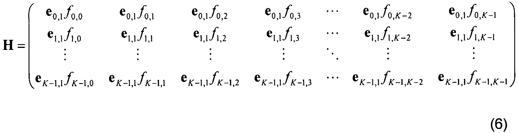
FIG. 4 , two code words are mapped into two layers according to per-symbol layer shifting.CW # 1 andCW # 2 are mapped intoLayer # 1 andLayer # 2, respectively at the first DFTS-OFDM symbol, whileCW # 1 andCW # 2 are mapped intoLayer # 2 andLayer # 1, respectively, at the second DFTS-OFDM symbol. IfCW # 1 is decoded first, the 2K × 1 vector symbol y" representing the frequency-domain received symbols after cancellation at the first DFTS-OFDM symbol is expressed as
- H is a 2K × K vector representing the equivalent channel (including the precoder and DFT),
- s" is a K × 1 vector representing the transmitted symbols after cancellation.
- e k,n is the n-th column vector of E k ,
- fk,l is the (k, l)-entry of F K .
- In equation, 6, each row of H consists of block matrices (vectors) which are given by scalar multiplications of the same matrix (vector). For example, each block matrix (vector) at the k-th row of H is a scalar multiplication of e k,l. Therefore, H is decomposed into a block-diagonal matrix (representing the per-subcarrier frequency-flat fading channel) and a unitary matrix (representing the per-layer DFT) as
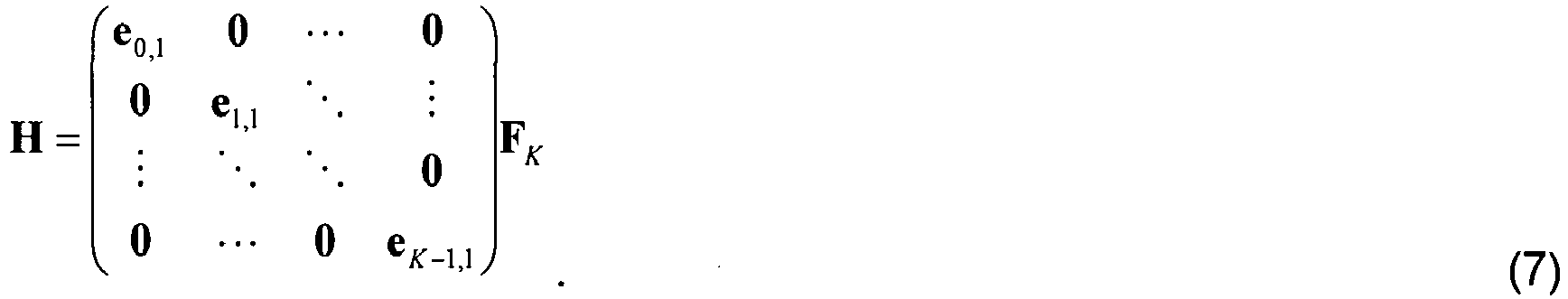
- Equations 6 and 7 hold true at the second DFTS-
OFDM symbol 112 as well. Consequently, the equalization is the per-subcarrier equalization followed by per-layer IDFT, which involves the same level of computational complexity as equalization without layer shifting. - In the present invention, the code words may be mapped to an arbitrary number of DFTS-OFDM symbols. It is evident that the number of different layer shifts equals the transmission rank. Thus, in the case of three layers, there are three different possible shifts of the layers. In general, it is preferable to ensure that a transport block experiences all possible shifts with as similar channels as possible. In addition, all the layer shifts are preferably applied in equal proportion. This maximizes the similarity in quality between all code words and is also beneficial for diversity.
- An equal proportion of layer shifts may be achieved by cycling through the different layer shifts over one subframe. If the number of data-carrying DFTS-OFDM symbols to which a transport block is mapped to during one subframe is an integer multiple of the transmission rank, each shift may be applied to the same number of DFTS-OFDM symbol instances for a code word. For deployments using normal cyclic prefix in LTE, there are 12 DFTS-OFDM symbols available for data. Since 12=1*12=2*6=3*4=4*3, all transmission ranks up to 4 are covered with a resulting balanced use of layer shifts within a subframe. However, for long cyclic prefix, there are only 10 DFTS-OFDM symbols available, which can then only handle transmission ranks up to 2 in a balanced manner.
- In the present invention, to rectify this problem, rather than letting the shifting pattern repeat for each subframe, in the present invention, the layer shifts may be applied so that different subframes see different patterns. To achieve this implementation, several steps are preferably performed.
FIG. 6 is a flow chart illustrating the steps of applying layer shifting where different subframes use different patterns. Instep 200, each possible layer shift is associated with a specific shift index i ∈ {0,1, ..., r -1} where r is the transmission rank. si denotes the layer shift associated with shift index i. Next, instep 204, the sequence of all data-carrying DFTS-OFDM symbols over consecutive subframes are ordered in increasing time and where k = 0,1,··· denotes the index of a certain DFTS-OFDM symbol in that sequence. Instep 206, the layer shift index and also the layer shift, to use for data-carrying DFTS-OFDM symbol k, are then determined as i = k mod r. - This procedure signifies that the layer shifts on average are used in a balanced manner, although it cannot always be guaranteed for a particular subframe. The index k may be made a function of the system frame number (SFN), the subframe number within a frame and the current DFTS-OFDM symbol within the subframe, all of which are known to both device-A and device-B.
- Various implementations for the approach described above may be used. For example, independent layer shift indices for the different Hybrid Automatic Repeat Request (HARQ) processes may be used. This implementation may increase the chance of more balanced use of the layer shifts for the same transport block in a situation where the transport block is retransmitted. This procedure may also be modified to accommodate such HARQ process independent shifting by using HARQ process specific DFTS-OFDM symbol indices k n in
step 204 ofFIG. 6 and then similarly HARQ process specific layer shift indices in instep 206 where n represents the HARQ process number. - The use of long cyclic prefix is not the only situation in which the layer shifts become unbalanced within a subframe. If sounding reference signals (SRS) are configured, the last DFTS-OFDM symbol in each subframe is removed and replaced by SRS. Thus, only 11 and 9 DFTS-OFDM symbols are available for data in normal and long cyclic prefix, respectively. The procedure discussed above may also be used in such situations.
- For complexity reasons in the receiver, in one embodiment, it may be advantageous to keep the same layer shift for a number of consecutive DFTS-OFDM symbols before switching to the next layer shift. This limits the number of recalculations of equalizer weights needed in the receiver. Such a modification may be achieved, for example, by using

step 204 ofFIG. 6 , where M is a parameter that controls the number of consecutive data-carrying DFTS-OFDM symbols for which the layer shift is kept fixed. - Although the present invention has been explained in terms of 3GPP LTE, this should not be seen as limiting the scope of the invention to only the aforementioned system. The present invention may also be implemented in other wireless systems, such as Wideband Code Division Multiple Access (WCDMA), Worldwide Interoperability for Microwave Access (WiMax), Ultra-Mobile Broadband (UMB) and Global System for Mobile Communications (GSM). In addition, terminology such as NodeB and UE has been used and does not imply a certain hierarchical relation between the two. The invention is layer shifting for multiple-stream transmission employing DFT-S-OFDMA.
- The present invention provides many advantages over existing systems. Since each codeword may be effectively transmitted over multiple layers, the present invention provides diversity gain which leads to improved error performance. The improved diversity typically also means the link adaption becomes more accurate. The perceived channel quality experienced by the different code words also becomes more similar, thereby reducing the loss associated with techniques such as Acknowledgment (ACK)/Negative Acknowledgment (NACK) bundling where multiple code words share the same ACK/NACK. Furthermore, since the codeword-to-layer mapping is fixed within a DFTS-OFDM symbol in the present invention, the resulting computational complexity of SIC at the receiver (equalization, reconstruction and cancellation) is exactly the same as that without layer shifting. Thus, the layer shifting improves the error performance without increasing the computational complexity. Additionally, the per-symbol layer shifting provides diversity gain, leading to improved error performance. Since the codeword-to-layer mapping is fixed within a DFTS-OFDM symbol, the equalization for SIC receivers is as simple as SIC receivers without layer shifting.
- As will be recognized by those skilled in the art, the innovative concepts described in the present application can be modified and varied over a wide range of applications. Accordingly, the scope of patented subject matter should not be limited to any of the specific exemplary teachings discussed above, but is instead defined by the following claims.

Claims (11)
- A method of layer shifting for multiple-stream transmission utilizing Discrete Fourier Transform Spread, DFTS,-Orthogonal Frequency Division Multiplexing, OFDM, access in a network, the method comprising the steps of:receiving (100) a signal having a plurality of code words and processing the signal for generating the multiple-stream transmission, wherein the multiple-stream transmission includes a plurality of subframes comprising a plurality of information carrying symbols (110, 112) transmitted on a plurality of layers (106, 108); andimplementing (102) per-symbol layer shifting on the multiple-stream transmission, wherein the per-symbol layer shifting is conducted upon each information carrying symbol (110, 112), wherein the plurality of information carrying symbols (110, 112) are DFTS-OFDM symbols (110, 112), wherein each DFTS-OFDM symbol (110, 112) includes the plurality of layers (106, 108), and wherein the step of implementing (102) per-symbol layer shifting includes:applying code word-to-layer mapping, wherein the code word-to-layer mapping is fixed within a DFTS-OFDM symbol (110, 112), to map the plurality of code words (102, 104) to the plurality of layers (106, 108); andonly shifting layers (106, 108) of the multiple-stream transmission across consecutive DFTS-OFDM symbols (110, 112) within the multiple-stream transmission, to transmit each code word (102, 104) over the plurality of layers (106, 108).
- The method according to claim 1, wherein a number of the DFTS-OFDM symbols (110, 112), mapped during one of the plurality of subframes, is an integer multiple of a number of the plurality of layers (106, 108) in the multiple-stream transmission.
- The method according to claim 1, wherein the step of implementing (102) per-symbol layer shifting includes cycling through different layers of the plurality of layers (106, 108) over one of the plurality of subframes of the multiple-stream transmission.
- The method according to claim 3, wherein the step of implementing (102) per-symbol layer shifting includes applying a different pattern of layer shift for each of the plurality of sub frames.
- The method according to claim 4, wherein the step of implementing (102) per-symbol layer shifting includes the steps of:associating each possible layer shift with a specific shift index based on a number of layers in the multiple-stream transmission;determining a sequence of all the DFTS-OFDM symbols (110, 112) over consecutive subframes, wherein the sequence is based on an increasing time order of the DFTS-OFDM symbols (110, 112); andapplying a layer shift index for implementing the per-symbol layer shifting based on the sequence.
- The method according to claim 1, wherein:the multiple-stream transmission includes a sounding reference signal, SRS; anda last DFTS-OFDM symbol (110, 112) in each of the plurality of subframes is removed and replaced by the SRS.
- The method according to claim 1, wherein the step of implementing (102) per-symbol layer shifting includes applying a same layer shift to a specified number of the consecutive DFTS-OFDM symbols (110, 112) before switching to another layer (106, 108).
- A system for layer shifting for multiple-stream transmission utilizing Discrete Fourier Transform Spread, DFTS,-Orthogonal Frequency Division Multiplexing, OFDM, access in a network, the system comprising:a first communication device (50, 52) having a mapping module (100) for receiving a signal having a plurality of code words and processing the signal for generating the multiple-stream transmission for transmission to a second communication device (52, 50), wherein the transmission includes a plurality of subframes comprising a plurality of information carrying symbols (110, 112) transmitted on a plurality of layers (106, 108); andmeans for implementing per-symbol layer shifting on the multiple-stream transmission, wherein the per-symbol layer shifting is conducted upon each information carrying symbol (110, 112), wherein the plurality of information carrying symbols (110, 112) are DFTS-OFDM symbols (110, 112), wherein each DFTS-OFDM symbol (110, 112) includes the plurality of layers (106, 108), wherein the means for implementing per-symbol layer shifting includes means adapted to:apply code word-to-layer mapping for mapping the plurality of code words (102, 104) to the plurality of layers (106, 108), wherein the code word-to-layer mapping is fixed within a DFTS-OFDM symbol (110, 112); andonly shift layers (106, 108) of the multiple-stream transmission across consecutive DFTS-OFDM symbols (110, 112) within the multiple-stream transmission, for transmission of each code word (102, 104) over the plurality of layers (106, 108) .
- The system according to claim 8, including means adapted to perform a method according to any one of claims 2 to 7.
- A node for layer shifting for multiple-stream transmission utilizing Discrete Fourier Transform Spread, DFTS,-Orthogonal Frequency Division Multiplexing, OFDM, access in a network, the node comprising:means (100) for receiving a signal having a plurality of code words and processing the signal for generating the multiple-stream transmission for transmission from the node being a first communication device (50, 52) to a second communication device (52, 50), wherein the transmission includes a plurality of subframes comprising a plurality of information carrying symbols (110, 112) transmitted on a plurality of layers (106, 108); andmeans for implementing per-symbol layer shifting on the multiple-stream transmission, wherein the per-symbol layer shifting is conducted upon each information carrying symbol (110, 112), wherein the plurality of information carrying symbols (110, 112) are DFTS-OFDM symbols (110, 112), wherein each DFTS-OFDM symbol (110, 112) includes the plurality of layers (106, 108), and wherein the means for implementing per-symbol layer shifting includes means adapted to:apply code word-to-layer mapping for mapping the plurality of code words (102, 104) to the plurality of layers (106, 108), wherein the code word-to-layer mapping is fixed within a DFTS-OFDM symbol (110, 112); andonly shift layers (106, 108) of the multiple-stream transmission across consecutive DFTS-OFDM symbols (110, 112) within the multiple-stream transmission, for transmission of each code word (102, 104) over the plurality of layers (106, 108).
- The node according to claim 10, including means adapted to perform a method according to any one of claims 2 to 7.
Applications Claiming Priority (2)
| Application Number | Priority Date | Filing Date | Title |
|---|---|---|---|
| US11394408P | 2008-11-12 | 2008-11-12 | |
| PCT/IB2009/007401 WO2010055387A2 (en) | 2008-11-12 | 2009-11-10 | System and method of single-carrier layer shifting for multiple-stream transmission facilitating sic implementation |
Publications (2)
| Publication Number | Publication Date |
|---|---|
| EP2356768A2 EP2356768A2 (en) | 2011-08-17 |
| EP2356768B1 true EP2356768B1 (en) | 2019-09-11 |
Family
ID=42170466
Family Applications (1)
| Application Number | Title | Priority Date | Filing Date |
|---|---|---|---|
| EP09756794.5A Active EP2356768B1 (en) | 2008-11-12 | 2009-11-10 | Symbol level layer shifting for multiple stream transmission using dft-spread ofdm |
Country Status (4)
| Country | Link |
|---|---|
| US (1) | US8824578B2 (en) |
| EP (1) | EP2356768B1 (en) |
| JP (1) | JP5638531B2 (en) |
| WO (1) | WO2010055387A2 (en) |
Families Citing this family (6)
| Publication number | Priority date | Publication date | Assignee | Title |
|---|---|---|---|---|
| SG182427A1 (en) | 2010-01-18 | 2012-08-30 | Ericsson Telefon Ab L M | Radio base station and user equipment and methods therein |
| US20130083826A1 (en) * | 2011-09-30 | 2013-04-04 | Fujitsu Limited | Spreading data symbols among multiple layers in a mimo transmission scheme |
| JP5916507B2 (en) * | 2012-05-11 | 2016-05-11 | シャープ株式会社 | TRANSMISSION DEVICE, RECEPTION DEVICE, TRANSMISSION METHOD, PROGRAM, AND INTEGRATED CIRCUIT |
| US9998315B2 (en) * | 2016-03-08 | 2018-06-12 | Blackberry Limited | Method and apparatus for I-Q decoupled OFDM modulation and demodulation |
| US10506608B1 (en) * | 2017-02-20 | 2019-12-10 | Sprint Spectrum L.P. | Selective distribution of MIMO layers among carriers |
| CN117914665A (en) | 2017-08-25 | 2024-04-19 | 华为技术有限公司 | Signal transmission method, device and system |
Family Cites Families (8)
| Publication number | Priority date | Publication date | Assignee | Title |
|---|---|---|---|---|
| JP3393926B2 (en) * | 1993-12-28 | 2003-04-07 | 株式会社東芝 | Photomask design method and apparatus |
| JP4576877B2 (en) * | 2004-05-10 | 2010-11-10 | ソニー株式会社 | Wireless communication system, wireless communication apparatus, wireless communication method, and computer program |
| EP2547003B1 (en) | 2006-09-06 | 2014-10-15 | Qualcomm Incorporated | Codeword permutation and reduced feedback for grouped antennas |
| KR101097640B1 (en) * | 2006-11-06 | 2011-12-22 | 콸콤 인코포레이티드 | Method and apparatus for a mimo transmission with layer permutation in a wireless communication system |
| US7986746B2 (en) * | 2006-12-30 | 2011-07-26 | Nortel Networks Limited | Content differentiated hierarchical modulation used in radio frequency communications |
| EP1942623A1 (en) * | 2007-01-08 | 2008-07-09 | Siemens Networks GmbH & Co. KG | Method for data transmission using a block guard interval, subscriber and system |
| WO2009134082A2 (en) * | 2008-04-29 | 2009-11-05 | Electronics And Telecommunications Research Institute | Apparatus and method for transmitting data using multiple antenna for single carrier frequency division multiple access system |
| US8705575B2 (en) * | 2008-07-03 | 2014-04-22 | Telefonaktiebolaget L M Ericsson (Publ) | Methods and arrangements in a wireless communication system using multi-codeword transmission and ACK/NACK compression |
-
2009
- 2009-11-10 WO PCT/IB2009/007401 patent/WO2010055387A2/en active Application Filing
- 2009-11-10 US US13/128,932 patent/US8824578B2/en active Active
- 2009-11-10 EP EP09756794.5A patent/EP2356768B1/en active Active
- 2009-11-10 JP JP2011535181A patent/JP5638531B2/en not_active Expired - Fee Related
Non-Patent Citations (1)
| Title |
|---|
| None * |
Also Published As
| Publication number | Publication date |
|---|---|
| US20110310932A1 (en) | 2011-12-22 |
| EP2356768A2 (en) | 2011-08-17 |
| WO2010055387A3 (en) | 2010-10-28 |
| JP5638531B2 (en) | 2014-12-10 |
| JP2012508497A (en) | 2012-04-05 |
| WO2010055387A2 (en) | 2010-05-20 |
| US8824578B2 (en) | 2014-09-02 |
Similar Documents
| Publication | Publication Date | Title |
|---|---|---|
| US9225575B2 (en) | Precoding for single transmission streams in multiple antenna systems | |
| JP5180299B2 (en) | Transmission method using delay diversity and space-frequency diversity | |
| US7974359B2 (en) | Methods and apparatus for mitigating multi-antenna correlation effect in communication systems | |
| KR101589463B1 (en) | Method and apparatus for transmitting control information in wireless communication system | |
| US9083399B2 (en) | Precoding for single transmission streams in multiple antenna systems | |
| RU2446574C2 (en) | Method for data transmission and receive using based on phase shift of precoding and transceiver to support same | |
| CN100553186C (en) | OFDM channel estimating and multiple transmit antennas are followed the tracks of | |
| US20140211726A1 (en) | Systems and Methods for SC-FDMA Diversity Transmission | |
| US8290081B2 (en) | Transmission/reception methods and modules for a multiple-carrier multiple-antenna system using training sequences | |
| US8570939B2 (en) | Methods and systems for choosing cyclic delays in multiple antenna OFDM systems | |
| EP2356768B1 (en) | Symbol level layer shifting for multiple stream transmission using dft-spread ofdm | |
| US7945005B2 (en) | Method and module for estimating transmission chanels of a multi-antenna multi-carrier system | |
| US20120063530A1 (en) | Communication device | |
| JP2007523550A (en) | Channel evaluator and method for evaluating channel transfer function, and apparatus and method for supplying pilot sequence | |
| KR100782925B1 (en) | Multiple Antenna Telecommunication System | |
| Cheema et al. | Performance comparison of space time block codes for different 5G air interface proposals | |
| WO2007111198A1 (en) | Transmission method and transmission device | |
| Hatakawa et al. | Development and experiment of linear and non-linear precoding on a real-time multiuser-MIMO testbed with limited CSI feedback | |
| WO2011162937A2 (en) | Method and apparatus for diversity transmission scheme in single-carrier fdma systems | |
| Ishaq et al. | Precoding in MIMO, OFDM to reduce PAPR (Peak to Average Power Ratio) | |
| WO2011016783A1 (en) | A method of communication |
Legal Events
| Date | Code | Title | Description |
|---|---|---|---|
| PUAI | Public reference made under article 153(3) epc to a published international application that has entered the european phase |
Free format text: ORIGINAL CODE: 0009012 |
|
| 17P | Request for examination filed |
Effective date: 20110610 |
|
| AK | Designated contracting states |
Kind code of ref document: A2 Designated state(s): AT BE BG CH CY CZ DE DK EE ES FI FR GB GR HR HU IE IS IT LI LT LU LV MC MK MT NL NO PL PT RO SE SI SK SM TR |
|
| DAX | Request for extension of the european patent (deleted) | ||
| STAA | Information on the status of an ep patent application or granted ep patent |
Free format text: STATUS: EXAMINATION IS IN PROGRESS |
|
| 17Q | First examination report despatched |
Effective date: 20180315 |
|
| GRAP | Despatch of communication of intention to grant a patent |
Free format text: ORIGINAL CODE: EPIDOSNIGR1 |
|
| STAA | Information on the status of an ep patent application or granted ep patent |
Free format text: STATUS: GRANT OF PATENT IS INTENDED |
|
| RIC1 | Information provided on ipc code assigned before grant |
Ipc: H04L 5/00 20060101AFI20190327BHEP Ipc: H04L 27/26 20060101ALI20190327BHEP |
|
| INTG | Intention to grant announced |
Effective date: 20190411 |
|
| GRAS | Grant fee paid |
Free format text: ORIGINAL CODE: EPIDOSNIGR3 |
|
| GRAA | (expected) grant |
Free format text: ORIGINAL CODE: 0009210 |
|
| STAA | Information on the status of an ep patent application or granted ep patent |
Free format text: STATUS: THE PATENT HAS BEEN GRANTED |
|
| AK | Designated contracting states |
Kind code of ref document: B1 Designated state(s): AT BE BG CH CY CZ DE DK EE ES FI FR GB GR HR HU IE IS IT LI LT LU LV MC MK MT NL NO PL PT RO SE SI SK SM TR |
|
| REG | Reference to a national code |
Ref country code: GB Ref legal event code: FG4D |
|
| REG | Reference to a national code |
Ref country code: CH Ref legal event code: EP |
|
| REG | Reference to a national code |
Ref country code: AT Ref legal event code: REF Ref document number: 1179895 Country of ref document: AT Kind code of ref document: T Effective date: 20190915 |
|
| REG | Reference to a national code |
Ref country code: DE Ref legal event code: R096 Ref document number: 602009059807 Country of ref document: DE Ref country code: IE Ref legal event code: FG4D |
|
| REG | Reference to a national code |
Ref country code: NL Ref legal event code: MP Effective date: 20190911 |
|
| REG | Reference to a national code |
Ref country code: LT Ref legal event code: MG4D |
|
| PG25 | Lapsed in a contracting state [announced via postgrant information from national office to epo] |
Ref country code: FI Free format text: LAPSE BECAUSE OF FAILURE TO SUBMIT A TRANSLATION OF THE DESCRIPTION OR TO PAY THE FEE WITHIN THE PRESCRIBED TIME-LIMIT Effective date: 20190911 Ref country code: SE Free format text: LAPSE BECAUSE OF FAILURE TO SUBMIT A TRANSLATION OF THE DESCRIPTION OR TO PAY THE FEE WITHIN THE PRESCRIBED TIME-LIMIT Effective date: 20190911 Ref country code: BG Free format text: LAPSE BECAUSE OF FAILURE TO SUBMIT A TRANSLATION OF THE DESCRIPTION OR TO PAY THE FEE WITHIN THE PRESCRIBED TIME-LIMIT Effective date: 20191211 Ref country code: NO Free format text: LAPSE BECAUSE OF FAILURE TO SUBMIT A TRANSLATION OF THE DESCRIPTION OR TO PAY THE FEE WITHIN THE PRESCRIBED TIME-LIMIT Effective date: 20191211 Ref country code: HR Free format text: LAPSE BECAUSE OF FAILURE TO SUBMIT A TRANSLATION OF THE DESCRIPTION OR TO PAY THE FEE WITHIN THE PRESCRIBED TIME-LIMIT Effective date: 20190911 Ref country code: LT Free format text: LAPSE BECAUSE OF FAILURE TO SUBMIT A TRANSLATION OF THE DESCRIPTION OR TO PAY THE FEE WITHIN THE PRESCRIBED TIME-LIMIT Effective date: 20190911 |
|
| PG25 | Lapsed in a contracting state [announced via postgrant information from national office to epo] |
Ref country code: LV Free format text: LAPSE BECAUSE OF FAILURE TO SUBMIT A TRANSLATION OF THE DESCRIPTION OR TO PAY THE FEE WITHIN THE PRESCRIBED TIME-LIMIT Effective date: 20190911 Ref country code: ES Free format text: LAPSE BECAUSE OF FAILURE TO SUBMIT A TRANSLATION OF THE DESCRIPTION OR TO PAY THE FEE WITHIN THE PRESCRIBED TIME-LIMIT Effective date: 20190911 Ref country code: GR Free format text: LAPSE BECAUSE OF FAILURE TO SUBMIT A TRANSLATION OF THE DESCRIPTION OR TO PAY THE FEE WITHIN THE PRESCRIBED TIME-LIMIT Effective date: 20191212 |
|
| REG | Reference to a national code |
Ref country code: AT Ref legal event code: MK05 Ref document number: 1179895 Country of ref document: AT Kind code of ref document: T Effective date: 20190911 |
|
| PG25 | Lapsed in a contracting state [announced via postgrant information from national office to epo] |
Ref country code: RO Free format text: LAPSE BECAUSE OF FAILURE TO SUBMIT A TRANSLATION OF THE DESCRIPTION OR TO PAY THE FEE WITHIN THE PRESCRIBED TIME-LIMIT Effective date: 20190911 Ref country code: PT Free format text: LAPSE BECAUSE OF FAILURE TO SUBMIT A TRANSLATION OF THE DESCRIPTION OR TO PAY THE FEE WITHIN THE PRESCRIBED TIME-LIMIT Effective date: 20200113 Ref country code: PL Free format text: LAPSE BECAUSE OF FAILURE TO SUBMIT A TRANSLATION OF THE DESCRIPTION OR TO PAY THE FEE WITHIN THE PRESCRIBED TIME-LIMIT Effective date: 20190911 Ref country code: NL Free format text: LAPSE BECAUSE OF FAILURE TO SUBMIT A TRANSLATION OF THE DESCRIPTION OR TO PAY THE FEE WITHIN THE PRESCRIBED TIME-LIMIT Effective date: 20190911 Ref country code: IT Free format text: LAPSE BECAUSE OF FAILURE TO SUBMIT A TRANSLATION OF THE DESCRIPTION OR TO PAY THE FEE WITHIN THE PRESCRIBED TIME-LIMIT Effective date: 20190911 Ref country code: AT Free format text: LAPSE BECAUSE OF FAILURE TO SUBMIT A TRANSLATION OF THE DESCRIPTION OR TO PAY THE FEE WITHIN THE PRESCRIBED TIME-LIMIT Effective date: 20190911 Ref country code: EE Free format text: LAPSE BECAUSE OF FAILURE TO SUBMIT A TRANSLATION OF THE DESCRIPTION OR TO PAY THE FEE WITHIN THE PRESCRIBED TIME-LIMIT Effective date: 20190911 |
|
| PG25 | Lapsed in a contracting state [announced via postgrant information from national office to epo] |
Ref country code: CZ Free format text: LAPSE BECAUSE OF FAILURE TO SUBMIT A TRANSLATION OF THE DESCRIPTION OR TO PAY THE FEE WITHIN THE PRESCRIBED TIME-LIMIT Effective date: 20190911 Ref country code: SM Free format text: LAPSE BECAUSE OF FAILURE TO SUBMIT A TRANSLATION OF THE DESCRIPTION OR TO PAY THE FEE WITHIN THE PRESCRIBED TIME-LIMIT Effective date: 20190911 Ref country code: SK Free format text: LAPSE BECAUSE OF FAILURE TO SUBMIT A TRANSLATION OF THE DESCRIPTION OR TO PAY THE FEE WITHIN THE PRESCRIBED TIME-LIMIT Effective date: 20190911 Ref country code: IS Free format text: LAPSE BECAUSE OF FAILURE TO SUBMIT A TRANSLATION OF THE DESCRIPTION OR TO PAY THE FEE WITHIN THE PRESCRIBED TIME-LIMIT Effective date: 20200224 |
|
| REG | Reference to a national code |
Ref country code: DE Ref legal event code: R097 Ref document number: 602009059807 Country of ref document: DE |
|
| REG | Reference to a national code |
Ref country code: CH Ref legal event code: PL |
|
| PLBE | No opposition filed within time limit |
Free format text: ORIGINAL CODE: 0009261 |
|
| STAA | Information on the status of an ep patent application or granted ep patent |
Free format text: STATUS: NO OPPOSITION FILED WITHIN TIME LIMIT |
|
| PG2D | Information on lapse in contracting state deleted |
Ref country code: IS |
|
| PG25 | Lapsed in a contracting state [announced via postgrant information from national office to epo] |
Ref country code: MC Free format text: LAPSE BECAUSE OF FAILURE TO SUBMIT A TRANSLATION OF THE DESCRIPTION OR TO PAY THE FEE WITHIN THE PRESCRIBED TIME-LIMIT Effective date: 20190911 Ref country code: DK Free format text: LAPSE BECAUSE OF FAILURE TO SUBMIT A TRANSLATION OF THE DESCRIPTION OR TO PAY THE FEE WITHIN THE PRESCRIBED TIME-LIMIT Effective date: 20190911 Ref country code: CH Free format text: LAPSE BECAUSE OF NON-PAYMENT OF DUE FEES Effective date: 20191130 Ref country code: LU Free format text: LAPSE BECAUSE OF NON-PAYMENT OF DUE FEES Effective date: 20191110 Ref country code: LI Free format text: LAPSE BECAUSE OF NON-PAYMENT OF DUE FEES Effective date: 20191130 Ref country code: IS Free format text: LAPSE BECAUSE OF FAILURE TO SUBMIT A TRANSLATION OF THE DESCRIPTION OR TO PAY THE FEE WITHIN THE PRESCRIBED TIME-LIMIT Effective date: 20200112 |
|
| 26N | No opposition filed |
Effective date: 20200615 |
|
| REG | Reference to a national code |
Ref country code: BE Ref legal event code: MM Effective date: 20191130 |
|
| PG25 | Lapsed in a contracting state [announced via postgrant information from national office to epo] |
Ref country code: SI Free format text: LAPSE BECAUSE OF FAILURE TO SUBMIT A TRANSLATION OF THE DESCRIPTION OR TO PAY THE FEE WITHIN THE PRESCRIBED TIME-LIMIT Effective date: 20190911 |
|
| PG25 | Lapsed in a contracting state [announced via postgrant information from national office to epo] |
Ref country code: IE Free format text: LAPSE BECAUSE OF NON-PAYMENT OF DUE FEES Effective date: 20191110 |
|
| PG25 | Lapsed in a contracting state [announced via postgrant information from national office to epo] |
Ref country code: BE Free format text: LAPSE BECAUSE OF NON-PAYMENT OF DUE FEES Effective date: 20191130 |
|
| PGFP | Annual fee paid to national office [announced via postgrant information from national office to epo] |
Ref country code: FR Payment date: 20201125 Year of fee payment: 12 Ref country code: GB Payment date: 20201127 Year of fee payment: 12 |
|
| PG25 | Lapsed in a contracting state [announced via postgrant information from national office to epo] |
Ref country code: CY Free format text: LAPSE BECAUSE OF FAILURE TO SUBMIT A TRANSLATION OF THE DESCRIPTION OR TO PAY THE FEE WITHIN THE PRESCRIBED TIME-LIMIT Effective date: 20190911 |
|
| PG25 | Lapsed in a contracting state [announced via postgrant information from national office to epo] |
Ref country code: MT Free format text: LAPSE BECAUSE OF FAILURE TO SUBMIT A TRANSLATION OF THE DESCRIPTION OR TO PAY THE FEE WITHIN THE PRESCRIBED TIME-LIMIT Effective date: 20190911 Ref country code: HU Free format text: LAPSE BECAUSE OF FAILURE TO SUBMIT A TRANSLATION OF THE DESCRIPTION OR TO PAY THE FEE WITHIN THE PRESCRIBED TIME-LIMIT; INVALID AB INITIO Effective date: 20091110 |
|
| PG25 | Lapsed in a contracting state [announced via postgrant information from national office to epo] |
Ref country code: TR Free format text: LAPSE BECAUSE OF FAILURE TO SUBMIT A TRANSLATION OF THE DESCRIPTION OR TO PAY THE FEE WITHIN THE PRESCRIBED TIME-LIMIT Effective date: 20190911 |
|
| PG25 | Lapsed in a contracting state [announced via postgrant information from national office to epo] |
Ref country code: MK Free format text: LAPSE BECAUSE OF FAILURE TO SUBMIT A TRANSLATION OF THE DESCRIPTION OR TO PAY THE FEE WITHIN THE PRESCRIBED TIME-LIMIT Effective date: 20190911 |
|
| GBPC | Gb: european patent ceased through non-payment of renewal fee |
Effective date: 20211110 |
|
| PG25 | Lapsed in a contracting state [announced via postgrant information from national office to epo] |
Ref country code: GB Free format text: LAPSE BECAUSE OF NON-PAYMENT OF DUE FEES Effective date: 20211110 |
|
| PG25 | Lapsed in a contracting state [announced via postgrant information from national office to epo] |
Ref country code: FR Free format text: LAPSE BECAUSE OF NON-PAYMENT OF DUE FEES Effective date: 20211130 |
|
| PGFP | Annual fee paid to national office [announced via postgrant information from national office to epo] |
Ref country code: DE Payment date: 20221125 Year of fee payment: 14 |