EP2597787A1 - Rahmenstruktur für ein drahtloses Mehrsprungsystem - Google Patents
Rahmenstruktur für ein drahtloses Mehrsprungsystem Download PDFInfo
- Publication number
- EP2597787A1 EP2597787A1 EP13156111.0A EP13156111A EP2597787A1 EP 2597787 A1 EP2597787 A1 EP 2597787A1 EP 13156111 A EP13156111 A EP 13156111A EP 2597787 A1 EP2597787 A1 EP 2597787A1
- Authority
- EP
- European Patent Office
- Prior art keywords
- frame
- relay station
- traffic
- downlink sub
- control information
- Prior art date
- Legal status (The legal status is an assumption and is not a legal conclusion. Google has not performed a legal analysis and makes no representation as to the accuracy of the status listed.)
- Withdrawn
Links
Images


Classifications
-
- H—ELECTRICITY
- H04—ELECTRIC COMMUNICATION TECHNIQUE
- H04L—TRANSMISSION OF DIGITAL INFORMATION, e.g. TELEGRAPHIC COMMUNICATION
- H04L45/00—Routing or path finding of packets in data switching networks
- H04L45/74—Address processing for routing
-
- H—ELECTRICITY
- H04—ELECTRIC COMMUNICATION TECHNIQUE
- H04B—TRANSMISSION
- H04B7/00—Radio transmission systems, i.e. using radiation field
- H04B7/14—Relay systems
-
- H—ELECTRICITY
- H04—ELECTRIC COMMUNICATION TECHNIQUE
- H04B—TRANSMISSION
- H04B7/00—Radio transmission systems, i.e. using radiation field
- H04B7/14—Relay systems
- H04B7/15—Active relay systems
- H04B7/155—Ground-based stations
-
- H—ELECTRICITY
- H04—ELECTRIC COMMUNICATION TECHNIQUE
- H04B—TRANSMISSION
- H04B7/00—Radio transmission systems, i.e. using radiation field
- H04B7/24—Radio transmission systems, i.e. using radiation field for communication between two or more posts
- H04B7/26—Radio transmission systems, i.e. using radiation field for communication between two or more posts at least one of which is mobile
- H04B7/2603—Arrangements for wireless physical layer control
- H04B7/2606—Arrangements for base station coverage control, e.g. by using relays in tunnels
-
- H—ELECTRICITY
- H04—ELECTRIC COMMUNICATION TECHNIQUE
- H04L—TRANSMISSION OF DIGITAL INFORMATION, e.g. TELEGRAPHIC COMMUNICATION
- H04L1/00—Arrangements for detecting or preventing errors in the information received
- H04L1/0001—Systems modifying transmission characteristics according to link quality, e.g. power backoff
- H04L1/0006—Systems modifying transmission characteristics according to link quality, e.g. power backoff by adapting the transmission format
-
- H—ELECTRICITY
- H04—ELECTRIC COMMUNICATION TECHNIQUE
- H04L—TRANSMISSION OF DIGITAL INFORMATION, e.g. TELEGRAPHIC COMMUNICATION
- H04L1/00—Arrangements for detecting or preventing errors in the information received
- H04L1/0078—Avoidance of errors by organising the transmitted data in a format specifically designed to deal with errors, e.g. location
- H04L1/0083—Formatting with frames or packets; Protocol or part of protocol for error control
-
- H—ELECTRICITY
- H04—ELECTRIC COMMUNICATION TECHNIQUE
- H04L—TRANSMISSION OF DIGITAL INFORMATION, e.g. TELEGRAPHIC COMMUNICATION
- H04L25/00—Baseband systems
- H04L25/02—Details ; arrangements for supplying electrical power along data transmission lines
- H04L25/03—Shaping networks in transmitter or receiver, e.g. adaptive shaping networks
- H04L25/03828—Arrangements for spectral shaping; Arrangements for providing signals with specified spectral properties
- H04L25/03866—Arrangements for spectral shaping; Arrangements for providing signals with specified spectral properties using scrambling
-
- H—ELECTRICITY
- H04—ELECTRIC COMMUNICATION TECHNIQUE
- H04L—TRANSMISSION OF DIGITAL INFORMATION, e.g. TELEGRAPHIC COMMUNICATION
- H04L5/00—Arrangements affording multiple use of the transmission path
- H04L5/003—Arrangements for allocating sub-channels of the transmission path
- H04L5/0053—Allocation of signaling, i.e. of overhead other than pilot signals
-
- H—ELECTRICITY
- H04—ELECTRIC COMMUNICATION TECHNIQUE
- H04L—TRANSMISSION OF DIGITAL INFORMATION, e.g. TELEGRAPHIC COMMUNICATION
- H04L5/00—Arrangements affording multiple use of the transmission path
- H04L5/14—Two-way operation using the same type of signal, i.e. duplex
- H04L5/1415—Two-way operation using the same type of signal, i.e. duplex using control lines
-
- H—ELECTRICITY
- H04—ELECTRIC COMMUNICATION TECHNIQUE
- H04L—TRANSMISSION OF DIGITAL INFORMATION, e.g. TELEGRAPHIC COMMUNICATION
- H04L5/00—Arrangements affording multiple use of the transmission path
- H04L5/14—Two-way operation using the same type of signal, i.e. duplex
- H04L5/1469—Two-way operation using the same type of signal, i.e. duplex using time-sharing
-
- H—ELECTRICITY
- H04—ELECTRIC COMMUNICATION TECHNIQUE
- H04W—WIRELESS COMMUNICATION NETWORKS
- H04W28/00—Network traffic management; Network resource management
- H04W28/02—Traffic management, e.g. flow control or congestion control
-
- H—ELECTRICITY
- H04—ELECTRIC COMMUNICATION TECHNIQUE
- H04L—TRANSMISSION OF DIGITAL INFORMATION, e.g. TELEGRAPHIC COMMUNICATION
- H04L2101/00—Indexing scheme associated with group H04L61/00
- H04L2101/60—Types of network addresses
- H04L2101/677—Multiple interfaces, e.g. multihomed nodes
-
- H—ELECTRICITY
- H04—ELECTRIC COMMUNICATION TECHNIQUE
- H04L—TRANSMISSION OF DIGITAL INFORMATION, e.g. TELEGRAPHIC COMMUNICATION
- H04L27/00—Modulated-carrier systems
- H04L27/26—Systems using multi-frequency codes
- H04L27/2601—Multicarrier modulation systems
- H04L27/2647—Arrangements specific to the receiver only
- H04L27/2655—Synchronisation arrangements
- H04L27/2656—Frame synchronisation, e.g. packet synchronisation, time division duplex [TDD] switching point detection or subframe synchronisation
-
- H—ELECTRICITY
- H04—ELECTRIC COMMUNICATION TECHNIQUE
- H04L—TRANSMISSION OF DIGITAL INFORMATION, e.g. TELEGRAPHIC COMMUNICATION
- H04L5/00—Arrangements affording multiple use of the transmission path
- H04L5/0001—Arrangements for dividing the transmission path
- H04L5/0014—Three-dimensional division
- H04L5/0016—Time-frequency-code
-
- H—ELECTRICITY
- H04—ELECTRIC COMMUNICATION TECHNIQUE
- H04L—TRANSMISSION OF DIGITAL INFORMATION, e.g. TELEGRAPHIC COMMUNICATION
- H04L5/00—Arrangements affording multiple use of the transmission path
- H04L5/003—Arrangements for allocating sub-channels of the transmission path
- H04L5/0037—Inter-user or inter-terminal allocation
- H04L5/0039—Frequency-contiguous, i.e. with no allocation of frequencies for one user or terminal between the frequencies allocated to another
-
- H—ELECTRICITY
- H04—ELECTRIC COMMUNICATION TECHNIQUE
- H04L—TRANSMISSION OF DIGITAL INFORMATION, e.g. TELEGRAPHIC COMMUNICATION
- H04L5/00—Arrangements affording multiple use of the transmission path
- H04L5/003—Arrangements for allocating sub-channels of the transmission path
- H04L5/0044—Arrangements for allocating sub-channels of the transmission path allocation of payload
Definitions
- This invention relates to wireless transmission systems which can support multi-hop transmission paths.
- WiMAX Worldwide Interoperability for Microwave Access
- IEEE 802.16-2004 specifies a Wireless MAN Air Interface for 'fixed' wireless metropolitan area networks, i.e. networks with static terminals.
- IEEE 802.16e Mobile WiMAX, now adopted as IEEE 802.16-2005
- the Mobile WiMAX Air Interface uses Orthogonal Frequency Division Multiple Access (OFDMA) for improved multi-path performance in non-line-of-sight environments.
- OFDMA Orthogonal Frequency Division Multiple Access
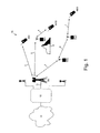
- FIG. 1 shows an example of a wireless network 10 which uses multi-hop transmission paths.
- a base station BS serves terminals MS1, MS2, MS3.
- Terminal MS1 is served directly by the base station BS via a single hop transmission path 2.
- Terminal MS2 is served by a two-hop transmission path 3, 4 via a relay station RS1.
- Terminal MS3 is served by a three-hop transmission path 5, 6, 7 via relay stations RS2 and RS3.
- a multi-hop transmission path may be needed when a single hop transmission path does not offer a sufficient quality. This can be due, for example, to a significant physical obstruction in the line-of-sight path between a base station BS and a terminal, such as the hill 8 shown between base station BS and terminal MS2.
- Relay stations can also be positioned at the edge of the normal coverage area of a base station to extend the coverage area of the base station.
- Base stations BS are interconnected via wired, or wireless, backhaul links 11 to a core network 12, which interconnects with other networks 14, such as data networks, the Internet or the PSTN.
- FIG. 2 shows the structure of an overall time-division duplex (TDD) frame defined by IEEE 802.16e (IEEE 802.16-2005).
- Base stations within the system alternately transmit to terminals on a downlink and receive from terminals on an uplink.
- Each frame is divided into a downlink part (DL) and an uplink part (UL).
- Time is shown along the horizontal axis and frequency is shown along the vertical axis.
- IEEE 802.16e uses an OFDM modulation scheme, with a set (e.g. 1024) of OFDM sub-carriers. Consequently, the horizontal time axis corresponds to OFDM symbols and the vertical frequency axis corresponds to OFDM sub-carriers.
- the downlink part begins with a 'preamble set' 31. This comprises a preamble, a Frame Control Head (FCH), a downlink map (DL-MAP) and an uplink map (UL-MAP).
- FCH Frame Control Head
- DL-MAP downlink map
- UL-MAP uplink map
- the preamble is used for synchronisation, and is the first OFDM symbol of the frame, extending across all OFDM sub-channels.
- the Frame Control Head (FCH) follows the preamble and provides the frame configuration information such as MAP message length and coding scheme and usable sub-channels.
- the DL-MAP carries control information for the DL section of the frame and carries information which allocates bursts within the DL part of the frame to individual stations.
- the UL-MAP carries information which allocates bursts within the UL part of the frame to individual stations and therefore defines when terminals can transmit.
- FIG. 3 shows a downlink sub-frame transmitted by a base station BS and a downlink sub-frame transmitted by a relay station RS, with both downlink sub-frames having a preamble set at the beginning of the frame.
- the transmissions of the base station BS and relay station RS must be synchronized.
- the relay station RS also needs to receive the preamble set 31 transmitted by the base station as this carries synchronisation information and information about which bursts within the frame are intended for the relay station.
- the scheme shown in Figure 3 would require a relay station RS to receive preamble set 31 from the base station at the same time as transmitting a preamble set to terminals MS. This will increase the complexity of equipment at a relay station as it requires a relay station to have receiver equipment which can operate at the same time as the relay station is transmitting data. It also requires a high-level of isolation between the receive path and transmit path which may be difficult, or impossible, to achieve in many relay station installations.
- a first aspect of the invention provides a method of transmitting within a wireless network comprising a base station, at least one terminal and at least one relay station, the method comprising transmitting a downlink sub-frame from the base station which comprises:
- Providing the second set of frame control information at a different position within the downlink sub-frame has an advantage that a relay station served by the base station does not need to receive frame control information at the same time as it transmits frame control information.
- a relay station is able to transmit a downlink sub-frame which includes a set of frame control information in the same position as that transmitted from the base station, typically at the start of the downlink sub-frame. This allows the relay station to appear to a terminal in the same manner as a base station.
- the relay station receives the second set of frame control information from the base station at a separate time during the downlink sub-frame.
- the invention is especially useful in a wireless network in which the downlink transmissions of a base station and a relay station are synchronised to one another and where the downlink transmissions of a base station and relay station occupy the same frequency bearer, or closely spaced frequency bearers.
- a second aspect of the invention provides a method of transmitting within a wireless network, the relay station forming part of a multi-hop path between a base station and a terminal, the method comprising:
- the method further comprises determining if the base station needs to directly serve a terminal or to serve a relay station which is part of a multi-hop path between the base station and a terminal having an odd number of hops and transmitting the first set of frame control information based on the determination.
- the base station can adapt the content of the downlink sub-frame.
- the base station does not need to transmit the second set of frame control information.
- the base station does not need to transmit the first set of frame control information.
- the base station can either reallocate the space within the downlink sub-frame which would have been occupied by the first set of frame control information to other downlink traffic, or it can simply not transmit within that part of the downlink sub-frame, which has an advantage in reducing interference within the network.
- a further aspect of the invention provides a method of operating a relay station within a wireless network comprising a base station, the relay station and a terminal, the method comprising:
- a further aspect of the invention provides a method of operating a relay station within a wireless network comprising a base station, a plurality of relay stations and a terminal, the method comprising:
- multi-hop paths of three or more hops can be realised while only requiring two positions within the downlink sub-frame to be reserved for frame control information.
- the position of frame control information within a downlink sub-frame will alternate between first and second positions.
- the second set of frame control information has a format which is modified compared to the format of the first set of frame control information.
- This modified format of the second set of frame control information can comprise encoding using a different pseudo noise (PN) code or encoding with an offset in the PN code.
- the modified format can comprise dividing the second set of frame control information into a plurality of segments which are distributed within the downlink sub-frame. The set of segments can additionally be coded with a different PN code, or an offset in the PN code.
- the terminal can be a mobile wireless station or a fixed wireless station.
- the relay station can be a dedicated relay station or a terminal which includes functionality to act as a relay station.
- the invention can be applied to a system in which transmission is time division duplexed (i.e. a downlink sub-frame and an uplink sub-frame share the same frequency bearer on a time divided basis), such as the TDD variant of IEEE 802.16.
- the invention can also be applied to a frequency division duplexed (FDD) scheme in which a downlink sub-frame and uplink sub-frame are transmitted on different frequency bearers.
- FDD frequency division duplexed
- the downlink and uplink sub-frames can occur at different times on the different frequency bearers, or there can be partial or full overlap between them.
- downlink traffic and uplink traffic to/from multiple terminals can share a common downlink and/or uplink sub-frame on a time multiplexed basis (TDMA).
- TDMA time multiplexed basis
- a frequency bearer can be realised as a set of frequency sub-channels, such as OFDM sub-channels, and the resources of the downlink and/or uplink sub-frames can be shared between multiple terminals on a frequency and/or time divided basis (e.g. OFDMA).
- the invention can be applied to High Speed OFDM Packet Access (HSOPA)/Long Term Evolution (LTE) and the Wireless World Initiative New Radio (WINNER) project.
- HSUPA High Speed OFDM Packet Access
- LTE Long Term Evolution
- WINNER Wireless World Initiative New Radio
- transceiver apparatus for a base station and a transceiver apparatus for a relay station which are arranged to implement the above methods, and any of the preferred features of the methods.
- the software may be stored on an electronic memory device, hard disk, optical disk or other machine-readable storage medium.
- the software may be delivered as a computer program product on a machine-readable carrier or it may be downloaded to the base station or relay station via a network connection.
- FIG. 1 a wireless system 10 of the type shown in Figure 1 in which a base station BS serves a set of terminals MS1-MS3 via direct transmission paths and via multi-hop transmission paths which use relay stations RS1-RS3.
- Figure 4 shows a first embodiment of a time-division duplexed transmission frame transmitted by a base station BS which is divided into a downlink sub-frame 20 and an uplink sub-frame 25.
- the base station BS, relay stations RS1-RS3 and terminals MS1-MS3 are all synchronised to the time-division duplexed transmission frame.
- the downlink sub-frame 20 transmitted by the base station is divided into two parts 30, 40.
- the first part 30 begins with a first preamble set 31.
- This first preamble set 31 carries control information which is intended for end terminals (e.g, mobile stations or fixed wireless terminals).
- the first preamble set 31 comprises a preamble, a Frame Control Head (FCH), a downlink map (DL-MAP) and an uplink map (UL-MAP).
- FCH Frame Control Head
- DL-MAP downlink map
- UL-MAP uplink map
- the remainder of part 30 of the downlink sub-frame 20 carries downlink traffic. This is divided into two portions: a first portion 36 is used to carry BS-RS traffic (i.e.
- the second part 40 of the downlink sub-frame 20 begins with a second preamble set 41.
- the second preamble set 41 has the same format as the first preamble set and comprises a preamble, a Frame Control Head (FCH), a downlink map (DL-MAP) and an uplink map (UL-MAP).
- FCH Frame Control Head
- DL-MAP downlink map
- UL-MAP uplink map
- the information contained within the second preamble set 41 is intended for relay stations within the system which are directly served by the base station, such as station RS1 in Figure 1 .
- the remainder of part 40 of the downlink sub-frame 20 carries further downlink traffic. This is divided into two portions: a first portion 46 is used to carry RS-MS traffic (i.e. traffic which is to be retransmitted by a relay, such as path 4 shown in Figure 1 ) and another portion 47 is used to carry BS-MS traffic (i.e. traffic which is to be delivered directly by the base station to a terminal).
- RS-MS traffic i.e. traffic which is to be retransmitted by a relay, such as path 4 shown in Figure 1
- BS-MS traffic i.e. traffic which is to be delivered directly by the base station to a terminal.
- the traffic transmissions of the BS (sections 36, 37, 47) and RS (section 46) are made orthogonal by placing them in different parts (in terms of time and frequency) of the downlink sub-frame. This helps to avoid any interference between the transmissions of the base station BS and relay stations RS.
- terminals and relay stations are individually allocated bursts at which they can transmit data within the uplink frame 25 and similarly this will prevent interference between uplink traffic from relay stations and uplink traffic from terminals.
- the downlink sub-frame 20 shown in Figure 4 will be received by relay stations RS and terminals MS.
- the downlink map (DL-MAP) carried within the first preamble set instructs a terminal where to find data intended for that terminal within the DL sub-frame. For example, it may instruct the terminal to find data within a particular burst (slot) within sections 37, 47.
- the downlink map (DL-MAP) carried within the second preamble set is received only by relay stations, and instructs a relay station where to find data within the downlink sub-frame 20, For example, it may instruct relay station RS1 to look in burst #3 within section 36.
- the relay station For the final hop to a terminal MS, the relay station generates data for the first preamble set 31. This causes the relay station to appear as a base station, thereby allowing backwards compatibility with existing terminals.
- the downlink sub-frame 20 includes several guard spaces which are to allow radio transceivers within the system sufficient time to switch between transmitting data and receiving data (or vice versa).
- Receive/Transmit Transition Gap (RTG) 22 at the beginning of the frame, allows the base station to switch between receiving data on the uplink and transmitting data on the downlink.
- Transmit/Receive Transition Gap (TTG) 23 allows the base station to switch between transmitting data on the downlink and receiving data on the uplink and, similarly, allows any terminals or relay stations to switch between receiving data on the downlink and transmitting data on the uplink.
- the gaps 22, 23 also prevent collisions between uplink and downlink traffic.
- RTG 22 and TTG 23 are conventional parts of an IEEE 802.16e TDD frame.
- TTG R 35 allows relay stations to switch between transmitting the first preamble set 31 on a downlink to terminals (or other relay station) and receiving data on a downlink from the base station (or other relay stations).
- RTG R 45 allows relay stations to switch between receiving the second preamble set 41 on a downlink from a base station (or other relay station) and transmitting data on a downlink to terminals, or other relay stations.
- TTG R and RTG R are added for the benefit of the relay station and so do not need to extend over all sub-carriers.
- the parts 37, 47 of the frame do not need to include these intervals.
- gaps 35, 45 are an integer number of symbols.
- Transmission by each relay station RS is preferably restricted to a narrow range of OFDM sub-channels and utilises the maximum time in order to make optimum use of RS power.
- Figure 5 shows a downlink sub-frame 120 transmitted by a relay station RS towards a terminal MS.
- a first preamble set 131 is transmitted by the relay station at the beginning of the downlink sub-frame.
- the first preamble set has the same format as the first preamble set transmitted by the base station (31, Figure 4 ) to ensure that it can be correctly received and decoded by an existing (legacy) terminal.
- the content of the first preamble set may be modified compared to the content of a first preamble set transmitted by a base station.
- the DL-MAP part of the first preamble set 131 transmitted by the relay station may only include data specifying the positions of data bursts within the downlink sub-frame for those terminals MS served by that relay station RS.
- this relay station transmits data within a burst 150 within section 146 of the frame reserved for RS-MS traffic.
- the transmissions of the relay station RS are orthogonal to the transmissions of the base station BS and any other relay stations RS, the downlink frame shown in Figure 5 does not include any other traffic, apart from the burst 150 which has been reserved for RS-MS traffic.
- the content of the DL-MAP transmitted by the relay station RS can differ from that transmitted by the base station BS.
- the DL-MAP within the first preamble set transmitted by a BS to include data for terminals served by relay stations RS.
- the DL-MAP within the second preamble set transmitted by a RS to include data for terminals served directly by a base station BS.
- a relay station RS transmits the first preamble set 131 of a downlink sub-frame.
- a base station transmits a first preamble set 31.
- the relay station ignores the first preamble set 31 transmitted by the base station.
- the relay station switches to receive, and begins to receive, and buffer, all downlink traffic 36 received from the base station.
- part 36 of the frame is used to transmit traffic between the base station BS and relay station RS and so the relay station only needs to receive and buffer traffic from part 36 of the frame. At this point the relay station does not know which of the buffered traffic is intended for itself.
- the relay station begins to receive the second preamble set 41 from the base station.
- the preamble is used to acquire synchronisation.
- a timing offset is applied to establish the beginning of the frame.
- the DL-MAP within the second preamble set 41 instructs the relays station which traffic it should relay.
- the DL-MAP may also specify to which terminal the relay station should retransmit the traffic, or a separate mechanism from the DL-MAP may be used to derive this information, such as a forwarding table derived from a routing algorithm.
- the relay station switches in preparation to transmit. In this example, relay station transmits at time t5 in a burst/slot 150.
- Terminals MS within the system will generally receive a downlink frame from the base station BS or from a relay station RS. If a terminal receives a frame directly from a base station BS of the type shown in Figure 4 , it will receive the first preamble set 31, acquire frame synchronisation using the preamble within the first preamble set 31, and will use the downlink map DL-MAP to determine when it should receive traffic within the downlink sub-frame.
- a terminal receives a frame directly from a relay station RS of the type shown in Figure 5 , it will receive the first preamble set 131, acquire frame synchronisation using the preamble within the first preamble set 131, and will use the downlink map DL-MAP to determine when it should receive traffic within the downlink sub-frame.
- the terminal is unaffected by the use of a relay station and the terminal does not need to be modified to receive transmissions via a relay station.
- a terminal MS may receive a downlink frame from a base station BS and one or more relay stations RS but, in most circumstances, one transmission will be received more strongly than another.
- the orthogonal division of the frame prevents interference between traffic transmissions of the base station BS and relay stations RS.
- a three-hop path will be considered where two intermediate relay stations (RS2, RS3 in Figure 1 ) are used.
- RS2, RS3 in Figure 1 two intermediate relay stations
- a further preamble set could be inserted into the downlink sub-frame for use by the further relay station but this will reduce the amount of resources available for carrying traffic.
- the first and second preamble sets are used in a manner which is shown in Figure 6 .
- the final relay station RS3 in the multi-hop path must transmit a first preamble set at the beginning of the frame, in the place where a terminal MS is expecting to find the preamble set. This governs what happens in the rest of the multi-hop path.
- the previous relay station RS2 along the path must transmit a second preamble set in the middle of the downlink sub-frame.
- relay station RS2 is transmitting a second preamble set it must receive a first preamble set from the base station BS at the beginning of the downlink sub-frame.
- this arrangement avoids the need for any relay station to simultaneously transmit and receive while making efficient use of the space within the downlink sub-frame reserved for preamble sets.
- the first preamble set transmitted by the base station BS is received by terminals MS directly served by the base station BS and relay station RS2.
- the second preamble set may be received by other relay stations, such as RS1 in Figure 1 .
- traffic on each of the hops alternates between the first traffic-carrying part 36 and the second traffic-carrying part 46 of the downlink sub-frame. This avoids the need for each of the relay stations to simultaneously transmit and receive traffic.
- the scheme can be applied to transmission paths of greater than three hops.
- Figure 7 shows a four-hop path between a base station BS and a terminal MS.
- the three relay stations between the base station BS and terminal MS are labelled RS1-RS3. These labels do not correspond to those used for the relay stations shown in Figure 1 .
- relay station RS3 transmits a first preamble set towards a terminal MS and receives a second preamble set from relay station RS2.
- Relay station RS2 transmits a second preamble set towards relay station RS3 and receives a first preamble set from relay station RS1.
- Relay station RS1 transmits a first preamble set towards relay station RS2 and receives a second preamble set from the base station BS.
- the base station BS transmits both the first and second preamble sets. Traffic on each of the hops alternates between the first traffic-carrying part 36 and the second traffic-carrying part 46 of the downlink sub-frame.
- a relay station needs to transmit traffic in traffic-carrying part 36 of the downlink sub-frame if it is transmitting a second preamble set and a relay station needs to transmit traffic in traffic-carrying part 46 of the downlink sub-frame if it is transmitting a first preamble set. This is because the downlink sub-frame does not include a gap between the end of traffic-carrying part 36 and the start of the second preamble set.
- varying the specific structure of the downlink sub-frame will allow other combinations, while following the general principle of alternately using the first and second traffic-carrying parts 36, 46 of the downlink sub-frame on adjacent hops.
- Each transmitting relay station RS should know how many hops are between itself and the terminal MS.
- the penultimate relay station RS should transit the preamble set in the middle of the frame.
- the position of the preamble set transmitted by relay stations earlier in the path will alternate, and will either be at the beginning of the frame if the next RS in the path towards the MS is transmitting in the middle of the frame, or in the middle of the frame if the next RS in the path towards the MS is transmitting at the beginning of the frame.
- the first hop from the base station BS will require the first relay station RS to receive the second preamble set 41.
- the first hop from the base station BS will require the first relay station RS to receive the first preamble set 31.
- Knowledge of the number of hops between a base station and a terminal, and knowledge of the position of a particular relay station within the overall multi-hop path, can be acquired by each relay station (a distributed routing scheme) or by the base station and subsequently disseminated to relay stations (a centralised routing scheme).
- Figures 4-7 show the downlink sub-frame 20 divided into roughly two equal parts 30, 40 with the second preamble set positioned mid-way within the downlink sub-frame 20.
- this is only shown as one example of a possible format for the downlink sub-frame.
- the division of the downlink sub-frame does not need to be equal.
- the division can be varied on a frame-by-frame basis, if necessary, according to the ratio between the different traffic categories (BS-RS traffic, RS-MS traffic, RS-RS traffic, BS-MS traffic).
- the frame format for a particular frame can be signalled in the preamble set.
- the second preamble set 41 can be positioned anywhere within the downlink sub-frame 20, other than the position occupied by the first preamble set 31.
- Figure 8 shows another example of a format for a downlink sub-frame in which the second preamble set 341 immediately follows the first preamble set 31.
- the space 337 between the end of the first preamble set 31 and the beginning of the second preamble set 341 is used to carry traffic, such as BS-MS traffic.
- the RS will be required to buffer the received frame up to the point at which the second preamble set is received.
- a relay station RS requires information in the second preamble set (especially the DL-MAP) to determine what data that RS should extract and relay. Therefore, all traffic received during the BS-RS section 336 of the downlink sub-frame should be buffered by the RS. Once the DL-MAP within the second preamble set has been received, the RS can determine what data within the buffer it needs to relay.
- the second preamble set 341 immediately follows the first preamble set 31, as shown in Figure 8 , buffering is not be required for this purpose (although it may be required for other reasons).
- the first preamble set 31 must always be at the beginning of the frame because this is where the MS expects to find it.
- Terminals within the wireless system look for the first preamble set within a received signal and use the preamble to acquire frame synchronisation.
- the preamble comprises a pseudo noise (PN) code sequence which is carried by a group of OFDM sub-carriers, with each sub-carrier being modulated to a particular constellation value.
- PN pseudo noise
- the preamble within the second preamble set can carry a different pseudo noise (PN) code sequence compared to the preamble within the first preamble set.
- Synchronisation acquiring circuitry in a terminal includes a correlator which attempts to correlate a locally-stored code sequence with the code sequence in a received signal. If the second preamble uses a different code to the one locally-stored at a terminal, the terminal cannot incorrectly sync to the second preamble.
- PN pseudo noise
- the preamble within the second preamble set can use a PN code sequence which is offset compared to the PN code sequence used for the preamble in the first preamble set. In this manner, a terminal will ignore the second preamble.
- the PN code is applied in the frequency domain, so sub-carrier 0 is XORed with symbol 0 of the code, sub-carrier 1 with symbol 1 and so on.
- the resulting coded sub-carriers are then passed through a frequency domain-to-time domain transform, such as an Inverse Fast Fourier Transform (IFFT).
- IFFT Inverse Fast Fourier Transform
- An offset can be applied to the code by simply XORing sub-carrier 0 with code symbol 10, sub-carrier 1 with symbol 11, and so on.
- the offset code has good cross-correlation properties with the original code, i.e. a low result is obtained if a receiver cross-correlates the offset code with the original code. This may be advantageous if the number of available codes is limited and there are insufficient to provide a different code to each base station and each relay. This situation may for example occur in a dense urban deployment.
- the second preamble set can be divided into a plurality of segments which are distributed within the downlink sub-frame.
- Figure 9 shows an example of a downlink sub-frame in which the second preamble set is distributed in this way.
- the preamble is divided into four segments 401-404.
- the downlink map DL-MAP is divided into three segments 406-408 and the uplink map UL-MAP is divided into two segments 409, 410.
- a relay station is provided with the knowledge of where the segments are positioned within the frame. It will be understood that the scheme shown in Figure 8 is only one example of how the segmentation can be achieved.
- Each part of the second preamble set (preamble, FCH, DL-MAP, UL-MAP) can be divided into a different number of segments, and the position of those segments within the frame can be different to what is shown.
- the segmentation of the second preamble set can be fixed, i.e. the second preamble set is always divided into the same number of segments which assume the same relative/absolute positions within the downlink sub-frame. In this case the knowledge of where to look for the segments of the second preamble set can be programmed (hard-wired) into each relay station.
- the segmentation of the second preamble set can be varied, either on a time-basis or on an area basis with, for example, different base stations using different segmentation scheme.
- the preamble of the distributed second preamble set is also coded differently to the preamble of the first preamble set, as described above.
- the preamble within a preamble set denotes the beginning of a frame to a terminal and is therefore the part of the preamble set which it is especially important to hide from terminals.
- the sync sequence in the second preamble can be combined with a random sequence which is designed to spoil the correlation properties, such as a scrambling sequence.
- a scrambling sequence This can occur in the frequency domain or in the time domain.
- the preamble is first multiplied (typically XORed) in the time domain by the scrambling code. In this manner, none of the terminals will confuse the scrambled sequence with a true sync sequence.
- a relay station RS when searching for the hidden symbol would first multiply (XOR) by the random sequence, to unscramble the samples, and then perform a correlation for the real sequence.
- the sync finding correlators in the relay station RS are augmented with this descrambling multiplier.
- the base station can either reallocate the space within the downlink sub-frame which would have been occupied by the second preamble set to other downlink traffic, or it can simply not transmit within that part of the downlink sub-frame. If a base station does not need to transmit the first preamble set the base station can either reallocate the space within the downlink sub-frame which would have been occupied by the first preamble set to other downlink traffic, or it can simply not transmit within that part of the downlink sub-frame.
- the option of not transmitting can have an advantage in reducing interference within the network, as terminals will now receive the first preamble set transmitted by relay stations without any interfering first preamble transmissions from the base station.
- traffic carrying parts 37, 47 of the downlink sub-frame can be reallocated to carrying relay station - terminal (RS-MS) or relay station - relay station (RS-RS) traffic. If there are no relay stations at all, the parts 36, 46 of the downlink sub-frame can be reallocated to carrying base station - terminal traffic.
- RS-MS relay station - terminal
- RS-RS relay station - relay station
- a base station can determine what type of stations (relay stations, terminals) it is serving, and the number of hops within each path, from information acquired when establishing a connection with each station and can vary the content of a downlink sub-frame based on this information.
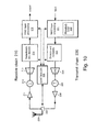
- FIG 10 shows a time-division duplex transceiver apparatus for a base station BS which implements the invention.
- the transceiver comprises an antenna 229 which connects to a Tx/Rx switch 228.
- the switch 228 alternately connects the transmit chain 220 to the antenna 30, to convey a high-power signal for transmission, or connects the antenna 229 to the receive chain 210 to convey a relatively low power received signal.
- a circulator can be used in place of the Tx/Rx switch 228.
- the receive chain 210 comprises an amplifier 211, a down-converter 212 which converts the received RF signal to an Intermediate Frequency (IF) or directly to base band, and an analog-to-digital conversion stage 213 which operates on the down-converted signal.
- the digitised signal is applied to a demodulation & decoding stage 214 where the digitized signal is demodulated, data is extracted from the uplink frame, and extracted data is decoded.
- Stage 214 feed
- the transmit chain 220 receives data for transmission.
- a MAC layer processing stage 221 performs functions such as scheduling data for transmission according to the intended destination and based on a requested quality of service.
- Stage 221 includes a framing unit 222 which assembles data into a frame having the structure previously described. Data for transmission is forwarded to an encoding and modulation stage 223 which prepares the data for transmission at the physical layer. Data is encoded to, for example, add error correction coding.
- the framing unit 223 generates the first and second preamble sets and inserts these into the frame at the appropriate positions. As described previously, the format of the frame can vary on a frame-by-frame basis according to factors such as the ratio of downlink-to-uplink traffic.
- each preamble set allows terminals and relay stations to correctly acquire synchronisation with the frame, and to process the frame.
- Each frame of data is modulated using an OFDM modulation scheme, the details of which are well-known.
- data is carried by a parallel set of sub-carriers, spaced apart in frequency.
- Data to be transmitted is mapped to constellation values on each of the sub-carriers and the resulting set of modulated sub-carriers are converted to the time-domain, such as by an Inverse Fast Fourier Transform (IFFT) operation.
- IFFT Inverse Fast Fourier Transform
- the encoded and modulated frame is forwarded to a digital-to-analog converter 224 and then an up-converter 225 which translates the modulated signal to RF.
- the up-converted signal is applied to a power amplifier 226 and on to the Tx/Rx switch 228 and antenna 229 for transmission.
- a controller 230 controls operation of the transceiver. Controller 230 collects information about the topology of the network (e.g, what connections exist, the number of hops in each connection) and instructs framing unit 223 to include the first and/or second preamble sets within a downlink sub-frame based on this information. This information can also be forwarded to relay stations within the network to allow them to establish their position within a multi-hop path.
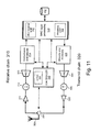
- FIG 11 shows a time-division duplex transceiver apparatus for use at a relay station RS to implement the invention.
- the transceiver has a receive chain 310 and transmit chain 320 which comprise the same stages as the receive and transmit chains of the base station which have just been described.
- a MAC processing stage 315 includes a de-framing unit 316 which receives a frame from the base station and extracts either the second preamble set or first preamble set from the signal, depending on the position of the relay station within a multi-hop path. Using data within the DL-MAP and UL-MAP fields of the preamble set, stage 315 extracts traffic which the relay station is required to relay.
- received data may be stored in buffer 332 until stage 315 is able to determine what traffic needs to be relayed.
- the data which needs to be relayed is assembled by a framing unit 322 within the MAC processing stage 315.
- the framing unit 322 Depending on the position of the relay within a multi-hop path, the framing unit 322 generates a first or a second preamble set for inclusion within the frame. If the relay station is serving a terminal, the first preamble set is generated.
- Framing unit 322 If the relay station is serving a further relay station, the first or second preamble set is generated, Framing unit 322 generates data for the DL-MAP which will allow a terminal or downstream relay station to find the relayed data within the downlink sub-frame.
- a controller 330 controls operation of the transceiver.
- the receive chain extracts timing information from the preamble within the first preamble set received from the base station BS and feeds this to synchronisation unit 331.
- Synchronisation unit 331 can use any well-known methods to acquire synchronisation in terms of time and frequency offset.
- Synchronisation unit 331 can, for example, use an autocorrelation technique to acquire information about a frequency offset in the received signal and can acquire synchronisation in terms of time by a cross-correlation technique which correlates a code sequence carried within the preamble of a preamble set with a locally-stored code sequence.
- Timing information derived by the synchronisation unit 331 is used by the transmit and receive chains and is used to control the Tx/Rx switch 328. Switch 328 will be operated during the guard periods 22, 23 between uplink and downlink sub-frames and during the additional guard periods 35, 45.
- Controller 330 can receive information from a base station, or can determine information for itself, about the position of the relay station within a multi-hop path. Based on this information, the relay station can determine whether it needs to receive a second preamble set and transmit a first preamble set, or to receive a first preamble set and transmit a second preamble set.
- the relay station receives to and transmits from the base station and (ii) transmits to and receives from a terminal or a downstream relay station.
- the transceiver can use a single antenna, or antenna array, for (i) and (ii) or it can use different antennas for (i) and (ii) with, for example, a directional antenna facing the base station BS and an antenna having a wider radiation pattern facing a region in which terminals are located.
- the antennas shown in Figures 10 and 11 can take the form of an antenna array which provides diversity transmission and/or diversity reception.
- the antenna can have an omni-directional radiation pattern or, more preferably, has a directional radiation pattern.
- the antenna can be a smart antenna which can adapt the radiation pattern according to the position of relays or terminals which the base station is serving.
Priority Applications (1)
| Application Number | Priority Date | Filing Date | Title |
|---|---|---|---|
| EP13156111.0A EP2597787A1 (de) | 2006-10-26 | 2007-10-23 | Rahmenstruktur für ein drahtloses Mehrsprungsystem |
Applications Claiming Priority (3)
| Application Number | Priority Date | Filing Date | Title |
|---|---|---|---|
| EP06022383A EP1916782A1 (de) | 2006-10-26 | 2006-10-26 | Rahmenstruktur für ein drahtloses Mehrsprungsystem |
| EP13156111.0A EP2597787A1 (de) | 2006-10-26 | 2007-10-23 | Rahmenstruktur für ein drahtloses Mehrsprungsystem |
| EP07821721A EP2084834A1 (de) | 2006-10-26 | 2007-10-23 | Rahmenstruktur für ein drahtloses mehrsprungsystem |
Related Parent Applications (1)
| Application Number | Title | Priority Date | Filing Date |
|---|---|---|---|
| EP07821721.3 Division | 2007-10-23 |
Publications (1)
| Publication Number | Publication Date |
|---|---|
| EP2597787A1 true EP2597787A1 (de) | 2013-05-29 |
Family
ID=38134165
Family Applications (5)
| Application Number | Title | Priority Date | Filing Date |
|---|---|---|---|
| EP06022383A Withdrawn EP1916782A1 (de) | 2006-10-26 | 2006-10-26 | Rahmenstruktur für ein drahtloses Mehrsprungsystem |
| EP13156117.7A Active EP2597788B1 (de) | 2006-10-26 | 2007-10-23 | Rahmenstruktur für ein drahtloses Multihop-System |
| EP07821721A Withdrawn EP2084834A1 (de) | 2006-10-26 | 2007-10-23 | Rahmenstruktur für ein drahtloses mehrsprungsystem |
| EP11179614A Withdrawn EP2393219A3 (de) | 2006-10-26 | 2007-10-23 | Rahmenstruktur für Multihop-Relais in einem drahtlosen Kommunikationssystem |
| EP13156111.0A Withdrawn EP2597787A1 (de) | 2006-10-26 | 2007-10-23 | Rahmenstruktur für ein drahtloses Mehrsprungsystem |
Family Applications Before (4)
| Application Number | Title | Priority Date | Filing Date |
|---|---|---|---|
| EP06022383A Withdrawn EP1916782A1 (de) | 2006-10-26 | 2006-10-26 | Rahmenstruktur für ein drahtloses Mehrsprungsystem |
| EP13156117.7A Active EP2597788B1 (de) | 2006-10-26 | 2007-10-23 | Rahmenstruktur für ein drahtloses Multihop-System |
| EP07821721A Withdrawn EP2084834A1 (de) | 2006-10-26 | 2007-10-23 | Rahmenstruktur für ein drahtloses mehrsprungsystem |
| EP11179614A Withdrawn EP2393219A3 (de) | 2006-10-26 | 2007-10-23 | Rahmenstruktur für Multihop-Relais in einem drahtlosen Kommunikationssystem |
Country Status (6)
| Country | Link |
|---|---|
| US (2) | US8917650B2 (de) |
| EP (5) | EP1916782A1 (de) |
| KR (4) | KR101392598B1 (de) |
| CN (3) | CN101595660B (de) |
| TW (1) | TWI469583B (de) |
| WO (1) | WO2008049843A1 (de) |
Families Citing this family (63)
| Publication number | Priority date | Publication date | Assignee | Title |
|---|---|---|---|---|
| US7873002B2 (en) * | 2006-09-19 | 2011-01-18 | Zte (Usa) Inc. | Frame structure for multi-hop relay in wireless communication systems |
| JP4915450B2 (ja) * | 2007-11-02 | 2012-04-11 | 富士通株式会社 | ネットワーク符号化方法およびネットワーク符号化装置 |
| KR20090106962A (ko) * | 2008-04-07 | 2009-10-12 | 삼성전자주식회사 | 다중 홉 릴레이 방식의 광대역 무선통신 시스템에서 서로다른 시스템 지원 장치 및 방법 |
| US20110310993A9 (en) * | 2008-07-07 | 2011-12-22 | Robert Novak | Preamble methods and techniques |
| US8488634B2 (en) * | 2008-07-07 | 2013-07-16 | Apple Inc. | Use of first and second preambles in wireless communication signals |
| EP2297872A1 (de) * | 2008-07-10 | 2011-03-23 | Telefonaktiebolaget L M Ericsson (PUBL) | Einfügung von signalen durch eine zwischeneinrichtung |
| US20100111229A1 (en) * | 2008-08-08 | 2010-05-06 | Assaf Kasher | Method and apparatus of generating packet preamble |
| US8259560B2 (en) * | 2008-08-29 | 2012-09-04 | Harris Corporation | Communication system allocating pilot sub-carriers and related methods |
| KR101520697B1 (ko) * | 2008-08-29 | 2015-05-21 | 엘지전자 주식회사 | 릴레이 시스템을 지원하기 위한 제어정보 전송방법 |
| WO2010031438A1 (en) * | 2008-09-19 | 2010-03-25 | Nokia Siemens Networks Oy | Network element and method of operating a network element |
| KR101465151B1 (ko) * | 2008-09-19 | 2014-11-25 | 노키아 솔루션스 앤드 네트웍스 오와이 | 네트워크 엘리먼트 및 네트워크 엘리먼트를 동작시키는 방법 |
| CN101730115B (zh) | 2008-10-24 | 2013-01-30 | 华为技术有限公司 | 中继传输的方法及设备 |
| WO2010048744A1 (zh) * | 2008-10-30 | 2010-05-06 | 上海贝尔阿尔卡特股份有限公司 | 接收下行链路数据帧中的数据的方法、移动台、基站和中继站 |
| JP5466241B2 (ja) * | 2008-10-30 | 2014-04-09 | アップル インコーポレイテッド | ダウンリンクでのユーザ装置に適した中継技法 |
| US8743904B2 (en) * | 2008-11-01 | 2014-06-03 | Lg Electronics Inc. | Data transmission method according to radio resource allocation in multi-hop relay system |
| KR101549025B1 (ko) | 2008-12-24 | 2015-09-02 | 엘지전자 주식회사 | 중계기에 대한 자원 할당 방법 |
| WO2010095871A2 (ko) * | 2009-02-18 | 2010-08-26 | 엘지전자 주식회사 | 중계기의 신호 송수신 방법 및 그 방법을 이용하는 중계기 |
| BRPI1008959B1 (pt) | 2009-03-13 | 2021-03-23 | Blackberry Limited | Sistemas de comunicação sem fio, método de comunicação sem fio implementado em um nó de acesso e método de comunicação sem fio implementado em um nó de retransmissão |
| US8982765B2 (en) * | 2009-03-17 | 2015-03-17 | Lg Electronics Inc. | Method and apparatus for transmitting data on relay communication system |
| FR2943882A1 (fr) * | 2009-03-27 | 2010-10-01 | Thomson Licensing | Procede d'emission pour un reseau sans fil et procede de reception correspondant |
| EP2416618A4 (de) * | 2009-03-31 | 2017-01-25 | Fujitsu Limited | Relaisstation, basisstation, relaisverfahren und kommunikationsverfahren in einem drahtlosen kommunikationsnetz |
| US8929303B2 (en) * | 2009-04-06 | 2015-01-06 | Samsung Electronics Co., Ltd. | Control and data channels for advanced relay operation |
| GB2469689A (en) * | 2009-04-24 | 2010-10-27 | Nec Corp | Relay communications system |
| KR101294815B1 (ko) | 2009-05-15 | 2013-08-08 | 엘지전자 주식회사 | 무선 통신 시스템에서 사운딩 참조 신호 송신 방법 및 이를 위한 장치 |
| CN101945483B (zh) * | 2009-07-07 | 2014-06-11 | 中兴通讯股份有限公司 | 一种上行中继子帧的传输方法及中继站 |
| KR101622227B1 (ko) | 2009-07-26 | 2016-05-18 | 엘지전자 주식회사 | 중계기를 위한 제어 정보 및 시스템 정보를 송수신하는 장치 및 그 방법 |
| JP5868322B2 (ja) | 2009-09-21 | 2016-02-24 | エルジー エレクトロニクス インコーポレイティド | 無線通信システムにおいてサウンディング参照信号の転送方法及びそのための装置 |
| JP5364849B2 (ja) | 2009-09-21 | 2013-12-11 | エルジー エレクトロニクス インコーポレイティド | 無線通信システムにおいてサウンディング参照信号の転送方法及びそのための装置 |
| JP2013515420A (ja) | 2009-12-22 | 2013-05-02 | 富士通株式会社 | リレーにおけるサービス品質の制御 |
| WO2011090259A2 (ko) * | 2010-01-19 | 2011-07-28 | 엘지전자 주식회사 | 무선 통신 시스템에서 사운딩 참조 신호 송신 방법 및 이를 위한 장치 |
| CN102763363B (zh) * | 2010-02-26 | 2015-08-19 | 瑞典爱立信有限公司 | 控制信息指派方法 |
| US9026122B2 (en) | 2010-03-12 | 2015-05-05 | Nokia Solutions And Networks Oy | Relay node operable with different spatial characteristic antenna patterns |
| WO2011136562A2 (ko) * | 2010-04-29 | 2011-11-03 | 엘지전자 주식회사 | 무선 통신 시스템에서 기지국과 릴레이 노드 간의 신호 송수신 방법 및 이를 위한 장치 |
| KR101453595B1 (ko) * | 2010-04-30 | 2014-11-03 | 한국전자통신연구원 | 무선 통신시스템에서 제어 채널 송수신 방법 |
| US8744340B2 (en) | 2010-09-13 | 2014-06-03 | Qualcomm Incorporated | Method and apparatus of obtaining timing in a repeater |
| CN102487294B (zh) * | 2010-12-01 | 2014-12-10 | 华为技术有限公司 | 中继通信方法和中继站 |
| US8971220B2 (en) * | 2010-12-02 | 2015-03-03 | Rockstar Consortium Us Lp | Dual mode base station |
| CN103430467B (zh) * | 2011-03-11 | 2016-05-11 | Lg电子株式会社 | 终端在应用了载波聚合技术的无线通信系统中发送/接收信号的方法和装置 |
| CN103650615A (zh) * | 2011-06-29 | 2014-03-19 | 瑞典爱立信有限公司 | 无线通信系统中的子载波分配 |
| US10716111B2 (en) | 2011-08-17 | 2020-07-14 | Skyline Partners Technology Llc | Backhaul radio with adaptive beamforming and sample alignment |
| US8467363B2 (en) | 2011-08-17 | 2013-06-18 | CBF Networks, Inc. | Intelligent backhaul radio and antenna system |
| US10708918B2 (en) | 2011-08-17 | 2020-07-07 | Skyline Partners Technology Llc | Electronic alignment using signature emissions for backhaul radios |
| US8761100B2 (en) * | 2011-10-11 | 2014-06-24 | CBF Networks, Inc. | Intelligent backhaul system |
| US10051643B2 (en) | 2011-08-17 | 2018-08-14 | Skyline Partners Technology Llc | Radio with interference measurement during a blanking interval |
| US8989762B1 (en) | 2013-12-05 | 2015-03-24 | CBF Networks, Inc. | Advanced backhaul services |
| US10548132B2 (en) | 2011-08-17 | 2020-01-28 | Skyline Partners Technology Llc | Radio with antenna array and multiple RF bands |
| US8385305B1 (en) | 2012-04-16 | 2013-02-26 | CBF Networks, Inc | Hybrid band intelligent backhaul radio |
| US10764891B2 (en) | 2011-08-17 | 2020-09-01 | Skyline Partners Technology Llc | Backhaul radio with advanced error recovery |
| US8502733B1 (en) | 2012-02-10 | 2013-08-06 | CBF Networks, Inc. | Transmit co-channel spectrum sharing |
| US9713019B2 (en) | 2011-08-17 | 2017-07-18 | CBF Networks, Inc. | Self organizing backhaul radio |
| US8928542B2 (en) | 2011-08-17 | 2015-01-06 | CBF Networks, Inc. | Backhaul radio with an aperture-fed antenna assembly |
| EP2745610B1 (de) * | 2011-08-19 | 2018-04-04 | SCA IPLA Holdings Inc. | Relaisvorrichtung und verfahren dafür |
| KR101425742B1 (ko) * | 2012-02-21 | 2014-08-05 | 연세대학교 산학협력단 | 릴레이 네트워크에서 채널 추정을 위한 트레이닝 시퀀스 생성, 프리코딩 방법과 그 장치 |
| US20130242974A1 (en) * | 2012-03-19 | 2013-09-19 | Htc Corporation | Method and Apparatus for Synchronization Mechanisms in Wireless Communication Systems |
| US10368261B2 (en) | 2014-05-09 | 2019-07-30 | Samsung Electronics Co., Ltd. | Synchronization method and apparatus for D2D communication |
| JP2017011689A (ja) | 2015-06-19 | 2017-01-12 | パナソニック インテレクチュアル プロパティ コーポレーション オブ アメリカPanasonic Intellectual Property Corporation of America | 送信方法、受信方法、送信装置、及び受信装置 |
| WO2016203750A1 (ja) | 2015-06-19 | 2016-12-22 | パナソニック インテレクチュアル プロパティ コーポレーション オブ アメリカ | 送信方法、受信方法、送信装置、及び受信装置 |
| WO2017027520A1 (en) * | 2015-08-11 | 2017-02-16 | Kyocera Corporation | Time division duplex (tdd) communication configuration for unconnected base stations |
| US10455455B2 (en) | 2016-11-04 | 2019-10-22 | Qualcomm Incorporated | Techniques for reservation preamble for prioritized medium contention in a new radio shared spectrum communication system |
| US11082121B2 (en) * | 2017-10-19 | 2021-08-03 | Mitsubishi Electric Corporation | “Apparatus and method for tranfering a communication signal while storing a detected preamble pattern” |
| WO2020017855A1 (ko) * | 2018-07-20 | 2020-01-23 | 엘지전자 주식회사 | 무선 통신 시스템에서 신호를 송수신하는 방법 및 이를 지원하는 장치 |
| US11310267B2 (en) * | 2019-04-29 | 2022-04-19 | Semiconductor Components Industries, Llc | Secure channel state information with adaptive obfuscation |
| CN113726400B (zh) * | 2021-09-02 | 2023-03-24 | 成都航空职业技术学院 | 一种用于无线通信的多功能电子系统及通信方法 |
Citations (1)
| Publication number | Priority date | Publication date | Assignee | Title |
|---|---|---|---|---|
| US20060046643A1 (en) * | 2004-09-01 | 2006-03-02 | Kddi Corporation | Wireless communication system, relay station device and base station device |
Family Cites Families (24)
| Publication number | Priority date | Publication date | Assignee | Title |
|---|---|---|---|---|
| US5668766A (en) * | 1996-05-16 | 1997-09-16 | Intel Corporation | Method and apparatus for increasing memory read access speed using double-sensing |
| EP1203458A4 (de) * | 1999-08-10 | 2002-11-05 | Airnet Communications Corp | Übersetzendes zwischenverstärkersystem mit verbesserter effizienz der verbindung zwischen verstärker und basisstation |
| CN1399818B (zh) * | 1999-08-10 | 2011-06-15 | 艾尔耐特通信公司 | 提高回程效率的差转中继系统和方法 |
| DE19950005A1 (de) * | 1999-10-18 | 2001-04-19 | Bernhard Walke | Verfahren zum Betrieb drahtloser Basisstationen für paketvermittelnde Funksysteme mit garantierter Dienstgüte |
| US7623859B2 (en) * | 2001-09-14 | 2009-11-24 | Atc Technologies, Llc | Additional aggregate radiated power control for multi-band/multi-mode satellite radiotelephone communications systems and methods |
| US7386036B2 (en) * | 2003-12-31 | 2008-06-10 | Spyder Navigations, L.L.C. | Wireless multi-hop system with macroscopic multiplexing |
| KR100754658B1 (ko) * | 2004-03-12 | 2007-09-03 | 삼성전자주식회사 | 통신 시스템에서 복합 재전송 운용 방법 |
| PL1808038T3 (pl) * | 2004-10-20 | 2013-09-30 | Deutsche Telekom Ag | Komórkowy rozległy system komunikacji radiowej z komórkami z ulepszonymi przekaźnikami |
| US7239659B2 (en) * | 2004-11-04 | 2007-07-03 | Motorola, Inc. | Method and apparatus for channel feedback |
| US7719972B2 (en) * | 2004-12-03 | 2010-05-18 | Intel Corporation | Methods and apparatus for providing an admission control system in a wireless mesh network |
| KR100839966B1 (ko) * | 2005-06-29 | 2008-06-20 | 삼성전자주식회사 | 통신 시스템에서 링크의 상태 보고 방법 및 시스템 |
| US7542439B2 (en) * | 2005-09-09 | 2009-06-02 | Intel Corporation | Methods and apparatus for providing a cooperative relay system associated with a broadband wireless access network |
| EP1804442A1 (de) | 2006-01-03 | 2007-07-04 | Samsung Electronics Co., Ltd. | Vorrichtung und Verfahren für transparente Weiterleitung in einem Multihop-Relay-Mobilfunknetz |
| WO2007100232A1 (en) * | 2006-03-03 | 2007-09-07 | Samsung Electronics Co., Ltd. | Apparatus and method for supporting relay service in a multi-hop relay broadband wireless access communication system |
| US20080031180A1 (en) * | 2006-08-03 | 2008-02-07 | Institute For Information Industry | Frame structure, wireless communication apparatus, and method for assigning the same |
| US8126392B2 (en) * | 2006-08-18 | 2012-02-28 | Fujitsu Limited | System and method for implementing a multi-radio wireless network |
| US8054817B2 (en) * | 2006-08-18 | 2011-11-08 | Fujitsu Limited | Legacy and new wireless communication device coexisting amble sequence |
| US8203994B2 (en) * | 2006-10-04 | 2012-06-19 | Industrial Technology Research Institute | Wireless communication systems, methods, and data structure |
| US8031604B2 (en) * | 2006-10-25 | 2011-10-04 | Sydir Jaroslaw J | Algorithm for grouping stations for transmission in a multi-phase frame structure to support multi-hop wireless broadband access communications |
| US20080165866A1 (en) * | 2007-01-08 | 2008-07-10 | Koon Hoo Teo | Cooperative Communication and Shared Handoff among Base, Relay, and Mobile Stations in OFDMA Cellular Networks |
| JP5145991B2 (ja) | 2008-02-07 | 2013-02-20 | 富士通株式会社 | 無線中継局 |
| US8249029B2 (en) * | 2008-03-28 | 2012-08-21 | Qualcomm Incorporated | Low reuse preamble for a wireless communication network |
| US8051240B2 (en) * | 2008-05-09 | 2011-11-01 | Sandisk Technologies Inc. | Compensating non-volatile storage using different pass voltages during program-verify and read |
| US7995388B1 (en) * | 2008-08-05 | 2011-08-09 | Anobit Technologies Ltd. | Data storage using modified voltages |
-
2006
- 2006-10-26 EP EP06022383A patent/EP1916782A1/de not_active Withdrawn
-
2007
- 2007-10-17 TW TW96138825A patent/TWI469583B/zh active
- 2007-10-23 KR KR1020147003594A patent/KR101392598B1/ko active IP Right Grant
- 2007-10-23 US US12/447,008 patent/US8917650B2/en active Active
- 2007-10-23 WO PCT/EP2007/061357 patent/WO2008049843A1/en active Application Filing
- 2007-10-23 EP EP13156117.7A patent/EP2597788B1/de active Active
- 2007-10-23 KR KR1020097010786A patent/KR101392592B1/ko active IP Right Grant
- 2007-10-23 EP EP07821721A patent/EP2084834A1/de not_active Withdrawn
- 2007-10-23 EP EP11179614A patent/EP2393219A3/de not_active Withdrawn
- 2007-10-23 CN CN200780047439.8A patent/CN101595660B/zh active Active
- 2007-10-23 CN CN201410303073.8A patent/CN104022815B/zh active Active
- 2007-10-23 EP EP13156111.0A patent/EP2597787A1/de not_active Withdrawn
- 2007-10-23 KR KR1020147003593A patent/KR101392599B1/ko active IP Right Grant
- 2007-10-23 CN CN201410302807.0A patent/CN104022814B/zh active Active
- 2007-10-23 KR KR1020147003595A patent/KR101392553B1/ko active IP Right Grant
-
2013
- 2013-07-17 US US13/944,424 patent/US9049156B2/en active Active
Patent Citations (1)
| Publication number | Priority date | Publication date | Assignee | Title |
|---|---|---|---|---|
| US20060046643A1 (en) * | 2004-09-01 | 2006-03-02 | Kddi Corporation | Wireless communication system, relay station device and base station device |
Also Published As
| Publication number | Publication date |
|---|---|
| US20100246475A1 (en) | 2010-09-30 |
| US20140050126A1 (en) | 2014-02-20 |
| US8917650B2 (en) | 2014-12-23 |
| KR20140032006A (ko) | 2014-03-13 |
| US9049156B2 (en) | 2015-06-02 |
| CN101595660B (zh) | 2014-05-28 |
| EP2393219A2 (de) | 2011-12-07 |
| EP2597788A1 (de) | 2013-05-29 |
| EP2393219A3 (de) | 2012-03-21 |
| CN104022815B (zh) | 2019-09-03 |
| CN104022814A (zh) | 2014-09-03 |
| KR20140025613A (ko) | 2014-03-04 |
| CN101595660A (zh) | 2009-12-02 |
| EP2597788B1 (de) | 2014-11-26 |
| KR101392553B1 (ko) | 2014-05-08 |
| KR101392599B1 (ko) | 2014-05-08 |
| KR101392592B1 (ko) | 2014-05-08 |
| CN104022814B (zh) | 2017-09-15 |
| TWI469583B (zh) | 2015-01-11 |
| KR20140024066A (ko) | 2014-02-27 |
| WO2008049843A1 (en) | 2008-05-02 |
| CN104022815A (zh) | 2014-09-03 |
| TW200826569A (en) | 2008-06-16 |
| EP1916782A1 (de) | 2008-04-30 |
| EP2084834A1 (de) | 2009-08-05 |
| KR20090083410A (ko) | 2009-08-03 |
| KR101392598B1 (ko) | 2014-05-08 |
Similar Documents
| Publication | Publication Date | Title |
|---|---|---|
| EP2597788B1 (de) | Rahmenstruktur für ein drahtloses Multihop-System | |
| JP4985217B2 (ja) | マルチホップ無線通信システム、ネットワーク管理エンティティ、ソース装置、中間装置、送信方法及びコンピュータプログラム | |
| JP4985218B2 (ja) | マルチホップ無線通信システム、ネットワーク管理エンティティ、ソース装置、中間装置、送信方法及びコンピュータプログラム | |
| KR101041639B1 (ko) | 멀티-홉 무선 통신 시스템에서 이용되는 송신 방법, 멀티-홉 무선 통신 시스템, 기지국, 중계국, 및 이동국 | |
| EP1890402B1 (de) | Vorrichtung und Verfahren zur Bereitstellung von Weiterleitungsdiensten in einem Multihop-Relay-Breitbandkommunikationssystem mit drahtlosem Zugang | |
| GB2440985A (en) | Wireless multi-hop communication system | |
| JP2009194901A (ja) | マルチキャリア無線通信システム、基地局、無線中継装置、移動局及びマルチキャリア無線通信方法 | |
| GB2440986A (en) | Wireless multi-hop communication system | |
| GB2443466A (en) | Relay station for multi-hop communication system | |
| US8068456B2 (en) | System and method for transmitting and receiving signals in a communication system using relay scheme | |
| KR101502561B1 (ko) | 전 이중 방식 릴레이와 반 이중 방식 릴레이가 공존하는 시스템을 위한 프레임 구성 장치 및 방법 |
Legal Events
| Date | Code | Title | Description |
|---|---|---|---|
| PUAI | Public reference made under article 153(3) epc to a published international application that has entered the european phase |
Free format text: ORIGINAL CODE: 0009012 |
|
| 17P | Request for examination filed |
Effective date: 20130221 |
|
| AC | Divisional application: reference to earlier application |
Ref document number: 2084834 Country of ref document: EP Kind code of ref document: P |
|
| AK | Designated contracting states |
Kind code of ref document: A1 Designated state(s): AT BE BG CH CY CZ DE DK EE ES FI FR GB GR HU IE IS IT LI LT LU LV MC MT NL PL PT RO SE SI SK TR |
|
| REG | Reference to a national code |
Ref country code: HK Ref legal event code: DE Ref document number: 1184916 Country of ref document: HK |
|
| 17Q | First examination report despatched |
Effective date: 20140627 |
|
| STAA | Information on the status of an ep patent application or granted ep patent |
Free format text: STATUS: THE APPLICATION IS DEEMED TO BE WITHDRAWN |
|
| 18D | Application deemed to be withdrawn |
Effective date: 20141108 |
|
| REG | Reference to a national code |
Ref country code: HK Ref legal event code: WD Ref document number: 1184916 Country of ref document: HK |