EP2597637A1 - Acoustic structure - Google Patents
Acoustic structure Download PDFInfo
- Publication number
- EP2597637A1 EP2597637A1 EP12193211.5A EP12193211A EP2597637A1 EP 2597637 A1 EP2597637 A1 EP 2597637A1 EP 12193211 A EP12193211 A EP 12193211A EP 2597637 A1 EP2597637 A1 EP 2597637A1
- Authority
- EP
- European Patent Office
- Prior art keywords
- resonance
- tubes
- opening
- boards
- resonance tubes
- Prior art date
- Legal status (The legal status is an assumption and is not a legal conclusion. Google has not performed a legal analysis and makes no representation as to the accuracy of the status listed.)
- Withdrawn
Links
- 230000000694 effects Effects 0.000 abstract description 49
- 239000013256 coordination polymer Substances 0.000 description 10
- 238000004804 winding Methods 0.000 description 7
- 230000000750 progressive effect Effects 0.000 description 6
- 230000003247 decreasing effect Effects 0.000 description 2
- 239000002245 particle Substances 0.000 description 2
- 230000002093 peripheral effect Effects 0.000 description 2
- 230000001419 dependent effect Effects 0.000 description 1
- 230000009189 diving Effects 0.000 description 1
- 230000012447 hatching Effects 0.000 description 1
Images



Classifications
-
- E—FIXED CONSTRUCTIONS
- E04—BUILDING
- E04B—GENERAL BUILDING CONSTRUCTIONS; WALLS, e.g. PARTITIONS; ROOFS; FLOORS; CEILINGS; INSULATION OR OTHER PROTECTION OF BUILDINGS
- E04B1/00—Constructions in general; Structures which are not restricted either to walls, e.g. partitions, or floors or ceilings or roofs
- E04B1/62—Insulation or other protection; Elements or use of specified material therefor
- E04B1/74—Heat, sound or noise insulation, absorption, or reflection; Other building methods affording favourable thermal or acoustical conditions, e.g. accumulating of heat within walls
- E04B1/82—Heat, sound or noise insulation, absorption, or reflection; Other building methods affording favourable thermal or acoustical conditions, e.g. accumulating of heat within walls specifically with respect to sound only
- E04B1/8209—Heat, sound or noise insulation, absorption, or reflection; Other building methods affording favourable thermal or acoustical conditions, e.g. accumulating of heat within walls specifically with respect to sound only sound absorbing devices
-
- G—PHYSICS
- G10—MUSICAL INSTRUMENTS; ACOUSTICS
- G10K—SOUND-PRODUCING DEVICES; METHODS OR DEVICES FOR PROTECTING AGAINST, OR FOR DAMPING, NOISE OR OTHER ACOUSTIC WAVES IN GENERAL; ACOUSTICS NOT OTHERWISE PROVIDED FOR
- G10K11/00—Methods or devices for transmitting, conducting or directing sound in general; Methods or devices for protecting against, or for damping, noise or other acoustic waves in general
- G10K11/16—Methods or devices for protecting against, or for damping, noise or other acoustic waves in general
- G10K11/175—Methods or devices for protecting against, or for damping, noise or other acoustic waves in general using interference effects; Masking sound
-
- E—FIXED CONSTRUCTIONS
- E04—BUILDING
- E04B—GENERAL BUILDING CONSTRUCTIONS; WALLS, e.g. PARTITIONS; ROOFS; FLOORS; CEILINGS; INSULATION OR OTHER PROTECTION OF BUILDINGS
- E04B1/00—Constructions in general; Structures which are not restricted either to walls, e.g. partitions, or floors or ceilings or roofs
- E04B1/99—Room acoustics, i.e. forms of, or arrangements in, rooms for influencing or directing sound
- E04B1/994—Acoustical surfaces with adjustment mechanisms
Definitions
- the present invention relates to an acoustic structure that is able to produce a sound-absorbing effect and a sound-scattering effect, thus preventing acoustic disturbance/trouble in an acoustic space.
- an acoustic structure including a plurality of pipes (or resonance tubes) having openings at their surfaces may produce a sound-absorbing effect and a sound-scattering effect via pipes so as to prevent acoustic disturbance/trouble (e.g. flutter echo) in an acoustic space (e.g. a sound chamber).
- Each pipe 25-m has a prismatic shape with an opening 27-m on a side face 26-m. All the pipes 25-m are equipped with the openings 27-m having the same opening area.
- the openings 27-m are formed at different positions on the side faces 26-m of the pipes 25-m along with the length direction.
- the acoustic structure 90 may produce a sound-absorbing effect and a sound-scattering effect based on a certain acoustic principle, which will be described with reference to Fig. 7.
- Fig. 7 shows a cross section of a pipe 25-m with an opening 27-m on a side face 26-m. It is possible to construe that the back cavity of the opening 27-m of the pipe 25-m is divided into a closed pipe portion CP L with a closed end 28 L -m and an open end using the opening 27-m, and another closed pipe portion CP R with a closed end 28 R -m and an open end using the opening 27-m.
- progressive waves may travel in the leftward direction from the open end (i.e. the opening 27-m) to the closed end 28 L -m of the closed pipe portion CP L while progressive waves may travel in the rightward direction from the open end (i.e. the opening 27-m) to the closed end 28 R -m of the closed pipe portion CP R .
- Leftward progressive waves are reflected on the closed end 28 L -m of the closed pipe portion CP L so that reflected waves may be retransmitted to the opening 27-m
- rightward progressive waves are reflected on the closed end 28 R -m of the closed pipe portion CP R so that reflected waves may be retransmitted to the opening 27-m.
- the closed pipe portion CP L combines progressive waves and reflected waves to produce standing waves with a node at the closed end 28 L -m and an antinode at the open end depending on particle velocity.
- the closed pipe portion CP R combines progressive waves and reflected waves to produce standing waves with a node at the closed end 28 R -m and an antinode at the open end depending on particle velocity.
- L L denotes the length of the closed pipe portion CP L (i.e. the length measured between the left-side closed end 28 L -m to the opening 27-m);
- L R denotes the length of the closed pipe portion CP R (i.e. the length measured between the right-side closed end 28 R -m to the opening 27-m);
- c denotes propagation speed of sound waves; and
- n is an integer equal to or greater than "1".
- Sound waves of the resonance frequency f L -n may reach the periphery of the opening 27-m of the side face 26-m while partially entering into the opening 27-m of the pipe 25-m.
- sound waves are reflected on the closed end 28L-m of the closed pipe portion CPL and then emitted from the opening 27-m toward an acoustic space. They have a reverse phase compared to the phase of sound waves entering into the opening 27-m from an acoustic space. Sound waves originated in an acoustic space are reflected on the periphery of the opening 27-m of the side face 26-m of the pipe 25-m without being involved in phase rotation.
- the closed pipe portion CP L may produce a sound-absorbing effect because sound waves incoming in the normal direction (or the front direction) of the opening 27-m of the side face 26-m interfere with reverse-phase sound waves, i.e. sound waves emitted out of the opening 27-m and sound waves reflected on the periphery of the opening 27-m of the side face 26-m. Additionally, a certain flow of air molecules may occur to cancel out phase discontinuity between sound waves emitted out of the opening 27-m and sound waves reflected on the periphery of the opening 27-m of the side face 26-m.
- the closed pipe portion CP R may produce a sound-absorbing effect in the normal direction (or the front direction) of the opening 27-m of the side face 26-m. Additionally, the closed pipe portion CP R may produce a sound-scattering effect in the periphery of the opening 27-m of the side face 26-m. As described above, each of the closed pipe portions CP L and CP R produces a sound-absorbing effect and a sound-scattering effect based on the above acoustic principle.
- Patent Literatures 1-3 disclose an acoustic structure which may operate based on the above acoustic principle. This acoustic structure is able to improve a sound-absorbing effect and a sound-scattering effect with a reduced area S O of an opening smaller than a sectional area S P of a cavity of a pipe. With sound waves entering into the cavity of the pipe from the opening of the acoustic structure, the behavior of a medium at the opening may depend on a specific acoustic impedance ratio ⁇ at the opening.
- the specific acoustic impedance ratio ⁇ is a complex ratio of an acoustic impedance ratio Z A at a certain point in a sound field to a characteristic impedance ratio Z C of a medium at a certain point.
- the specific acoustic impedance ratio ⁇ at a certain point of the opening 27-m receiving sound waves at a certain frequency is given by Equation (3), where j denotes an imaginary unit; L L denotes the length of the closed pipe portion CP L ; L R denotes the length of the closed pipe portion CP R ; and k denotes a wave number (specifically, a value of 2 ⁇ f/c which is produced by diving angular velocity 2 ⁇ f of an incoming wave by sound speed c, where f denotes frequency).
- ⁇ Z A
- Z C - j ⁇ S O S P ⁇ cos k ⁇ L L ⁇ cos k ⁇ L R sin k ⁇ L + L R
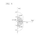
- Fig. 8 shows the known relationship between the phase of an incoming wave and the phase of a reflected wave on the opening of a pipe included in an acoustic structure.
- a phase difference ⁇ between an incoming wave at the interface of a medium and a reflected wave reflected on the interface of a medium may be equal to ⁇ 180° (i.e. their phases are reverse to each other).
- ⁇ 1 i.e. a graphic region outside a semicircular region with hatching on a Gaussian plane shown in Fig.
- the phase difference ⁇ becomes smaller than ⁇ 90°.
- the acoustic structure of Fig. 6 may maximize a sound-absorbing effect and a sound-scattering effect when the absolute value
- the acoustic structure may not produce a sound-absorbing effect and a sound-scattering effect substantially when the absolute value
- Equation (3) stipulating the relationship between the specific acoustic impedance ratio ⁇ and the ratio S O /S P (i.e. the ratio of the area S O of the opening of a pipe to the sectional area Sp of the cavity), it is possible to increase the bandwidth of a band causing a sound-absorbing effect and a sound-scattering effect close to the resonance frequencies f L -n, f R -n (i.e. a band in which the absolute value
- Fig. 9 shows the result of experiments which the inventor of this application (i.e.
- Patent Literature 1 the inventor of Patent Literature 1 conducted to evaluate the foregoing behavior of a pipe in an acoustic structure.
- the inventor of this application attempted to evaluate the behavior of a single pipe with dimensions described in Table relating to the length L L of the closed pipe portion CP L , the length L R of the closed pipe portion CP R , and the ratio S O /S P between the area S O of the opening and the sectional area S P of the cavity perpendicular to the opening, thus calculating the absolute, value
- the bandwidth of a band causing a sound-absorbing effect and a sound-scattering effect with a pipe of an acoustic structure depends on the ratio between the opening area and the sectional area of the cavity of a pipe.
- the conventional acoustic structure is unable to change the ratio between the opening area and the sectional area of the cavity of a pipe; hence, it is impossible to adjust the bandwidth of a band causing a sound-absorbing effect and a sound-scattering effect in an acoustic space (e.g. a sound chamber) equipped with an acoustic structure.
- the present invention is directed to an acoustic structure (e.g. an acoustic tuning panel) including a plurality of boards and a plurality of resonance tubes with a plurality of openings.
- the openings are formed at different positions on the side faces of the resonance tubes.
- the acoustic structure allows users to mutually move the resonance tubes so as to independently adjust the opening area of the resonance tube. In other words, it is possible to adjust the ratio of the opening area of the resonance tube to the sectional area of the internal cavity of the resonance tube, thus adjusting the bandwidth of a band causing a sound-absorbing effect and a sound-scattering effect in an acoustic space (e.g. a sound chamber).
- an acoustic space e.g. a sound chamber
- one resonance tube may be divided into two tubes, which are combined together with their open ends, and interposed in a pair of boards, wherein it is possible to adjust the opening area by moving two boards close to each other or apart from each other.
- one board may be divided into two boards, which are combined together with their distal ends, and interposed in a pair of resonance tubes having their openings, wherein it is possible to adjust the total opening area by moving two boards close to each other or apart from each other in connection with the openings of the resonance tubes.
- Fig. 1A is a front view of an acoustic structure 10 according to a first embodiment of the present invention.
- Fig. 1B is a side view of the acoustic structure 10 viewed in a direction B.
- Fig. 1C is a cross-sectional view taken along line C-C in Fig. 1A .
- the resonance tube 1-i includes an internal cavity encompassed by side faces, one of which is equipped with an opening.
- the acoustic structure 10 is designed to manually adjust the opening area of the resonance tube 1-i.
- Each of the tubes 2U-i, 2D-i has a prismatic shape with an open end OE and a closed end CE.
- the length of the tube 2U-i and the length of the tube 2D-i are differentiated depending on the resonance tube 1-i, but the sum of the lengths of the tubes 2U-i, 2D-i is the same among the resonance tubes 1-i.
- the resonance tube 1-1 includes a length D1U of the tube 2U-1 and a length D1D of the tube 2D-1;
- the resonance tube 1-2 includes a length D2U of the tube 2U-2 and a length D2D of the tube 2D-2;
- the resonance tube 1-3 includes a length D3U of the tube 2U-3 and a length D3D of the tube 2D-3;
- the resonance tube 1-4 includes a length D4U of the tube 2U-4 and a length D4D of the tube 2D-4;
- the resonance tube 1-5 includes a length D5U of the tube 2U-5 and a length D5D of the tube 2D-5.
- a pair of the boards 3-i supports the resonance tube 1-i, interposed therebetween, such that the open ends OE of the tubes 2U-i, 2D-i are positioned opposite to each other with a hole H-i (serving as an opening) therebetween and such that the tubes 2U-i, 2D-i can move mutually in an axial direction.
- each of the tubes 2U-i, 2D-i included in the resonance tube 1-i has projections XL, XR on the left and right faces thereof, wherein the projections XL, XR are elongated in the length direction of the resonance tube 1-i.
- each of the boards 3-2 to 3-5 has recesses YL, YR on the left and right faces thereof, wherein the recesses YL, YR are elongated in the length direction of the board 3-i.
- the board 3-1 has a recess YR, elongated in the length direction, on the right face thereof, while the board 3-6 has a recess YL, elongated in the length direction, on the left face thereof.
- the projections XL, XR formed on the left/right sides of the tubes 2U-i, 2D-i have a trapezoidal shape in cross section with the width gradually increased in a direction departing from the left/right faces as shown in Fig. 1B .
- the recesses YL, YR formed on the left/right sides of the board 3-i have a trapezoidal shape in cross section with the width gradually decreased in a direction approaching to the left/right faces as shown in Fig. 1C .
- the projections XL, XR of the tubes 2U-i, 2D-i are engaged with the recesses YR, YL of the boards 3-i, 3-i+1 sandwiching the resonance tube 1-i.
- the exterior walls of the projections XL of the tubes 2U-i, 2D-i are brought into contact with the interior walls of the recess YR of the board 3-i via contact friction, while the exterior walls of the projections XR of the tubes 2U-i, 2D-i are brought into contact with the interior walls of the recess YL of the board 3-i via contact friction.
- the resonance tube 1-i is engaged with the boards 3-i, 3i+1 via the projections XL, XR and the recesses YL, YR such that the tubes 2U-i, 2D-i can slide along the boards 3-i, 3-i+1 against contact friction exerted therebetween.
- the acoustic structure 10 shown in Figs. 1A to 1C may allow the user to collectively move the five resonance tubes 1-i, sandwiched between the six boards 3-i, in the axial direction, thus adjusting the sizes of the holes H-i; but this is not a restriction.
- the resonance tubes 1-2, 1-4, 1-7 are adjusted to close the holes H-2, H-4, H-7, which are formed at different positions.
- the resonance tubes 1-6, 2-8 are adjusted to fully open the holes H-6, H-8, which are formed at different positions.
- the resonance tubes 1-1, 1-3, 1-5 are adjusted to open the holes H-1, H-3, H-5 halfway, which are formed at different positions. That is, each resonance tube 1-i can be independently adjusted in terms of the length, the position of the hole H-i, and the opening area of the hole H-i. It is possible to selectively adjust the resonance tube 1-i having a desired resonance frequency and to adjust the opening area of the hole H-i, thus achieving a sound-absorbing effect and a sound-scatting effect at a desired band of frequency.
- the first embodiment of the acoustic structure 10 may produce the outstanding effects as follows.
- the acoustic structure 10 of the first embodiment is characterized by using two tubes 2U-i, 2D-i for each resonance tube 1-i, wherein it is possible to increase the opening area of the hole H-i, serving as the opening of the resonance tube 1-i, by moving the tubes 2U-i, 2D-i apart from each other, while it is possible to reduce the opening area of the hole H-i by moving the tubes 2U-i, 2D-i close to each other.
- the first embodiment is capable of adjusting the bandwidth of a band causing a sound-absorbing effect and a sound-scattering effect.
- the first embodiment is capable of adjusting the ratio of the opening area of the resonance tube 1-i to the sectional area of the cavity of the resonance tube 1-i, thus appropriately adjusting the bandwidth of a band causing a sound-absorbing effect and a sound-scattering effect.
- the acoustic structure 10 of the first embodiment is characterized in that the sum of the lengths of the tubes 2U-i, 2D-i is the same among the resonance tubes 1-i.
- the resonance tubes 1-i are each shortened such that the tubes 2U-i, 2D-i approach each other and come in contact with each other with their open ends OE, the acoustic structure 10 is entirely formed in a rectangular parallelepiped shape with a large width.
- the acoustic structure 10 of the first embodiment is characterized in that different lengths are set to the tubes 2U-i, 2D-i among the resonance tubes 1-i. This realizes different resonance frequencies for the resonance tubes 1-i. Thus, it is possible to reduce deviations between bandwidths of bands causing a sound-absorbing effect and a sound-scattering effect.
- Fig. 2A is a front view of an acoustic structure 10A according to a second embodiment of the present invention.
- Fig. 2B is a side view of the acoustic structure 10A viewed in a direction B in Fig. 2A.
- Fig. 2C is a cross-sectional view taken along line C-C in Fig. 2A .
- parts identical to those shown in Figs. 1A, 1B, 1C are denoted using the same reference signs.
- Fig. 2B does not include the reference signs of the projections XL, XR and the recesses YL, YR.
- the sheet member 4-i is a movable adjuster for shielding the hole H-i, which is formed between the open ends OE of the tubes 2U-i, 2D-i facing each other.
- the support member 5L-i, 5R-i support the sheet member 4-i to freely move in the axial direction of the resonance tube 1-i.
- the sheet member 4-i has a square shape whose width is slightly smaller than the widths of the tubes 2U-i, 2D-i.
- the support members 5L-i, 5R-i have a rectangular parallelepiped shape whose width is adequately larger than the widths of the tubes 2U-i, 2D-i.
- the support members 5L-i, 5R-i are fixed to the left/right positions on a side face AS of the tube 2D-i such that the left/right ends of the sheet member 4-i are held between the support members 5L-i, 5R-i and the side face AS of the tube 2D-i.
- the left/right ends on the surface and the backside of the sheet member 4-i are engaged with gaps formed between the support members 5L-i, 5R-i and the side face AS of the tube 2D-i such that the sheet member 4-i can vertically slide along gaps, formed between the support members 5L-i, 5R-i and the side face AS of the tube 2D-i, against contact friction exerted therebetween.
- the sheet member 4-i With upward force applied to the sheet member 4-i, the sheet member 4-i is moved upwardly in a direction from the tube 2D-i to the tube 2U-i so that the upper portion thereof can be slightly projected above the open end OE of the tube 2D-i.
- the projected portion of the sheet member 4-i may shield the opening, i.e. the hole H-i formed between the open ends OE of the tubes 2D-i, 2U-i.
- the acoustic structure 10A of the second embodiment is capable of adjusting the opening area of the hole H-i, which is formed between the tubes 2U-i, 2D-i, with the sheet member 4-i which can be moved upwardly/downwardly to shield the opening, i.e. the hole H-i.
- the sheet member 4-i which can be moved upwardly/downwardly to shield the opening, i.e. the hole H-i.
- Fig. 3A is a front view of an acoustic structure 10B according to a third embodiment of the present invention.
- Fig. 3B is a side view of the acoustic structure 10A viewed in a direction B in Fig. 3A.
- Fig. 3C is a cross-sectional view taken along line C-C in Fig. 3A .
- a pair of boards 8U-j, 8D-j is held between a pair of resonance tubes 6-j, 6j+1 which are horizontally aligned to adjoin each other.
- the resonance tube 6-j has three pairs of side faces positioned opposite to each other, i.e. a pair of side faces UW, DW, a pair of side faces FW, BW, and a pair of side faces LW, RW.
- Fig. 3A does not include the reference signs UW, DW, FW, BW, LW, RW with regard to the resonance tubes 6-2 to 6-5 except for the resonance tube 6-1. All the resonance tubes 6-j have the same length.
- a pair of openings 7L-j, 7R-j is formed on a pair of side faces LW, RW which are positioned opposite to each other in a pair of resonance tubes 6-j which adjoin each other via a pair of boards 8U-j, 8D-j.
- an opening 7R-1 on the side face RW of the resonance tube 6-1 is positioned opposite to an opening 7L-2 on the side face LW of the resonance tube 6-2 via a pair of boards 8U-1, 8D-1; an opening 7R-2 on the side face RW of the resonance tube 6-2 is positioned opposite to an opening 7L-3 on the side face LW of the resonance tube 6-3 via a pair of boards 8U-2, 8D-2; an opening 7R-3 on the side face RW of the resonance tube 6-3 is positioned opposite to an opening 7L-4 on the side face LW of the resonance tube 6-4 via a pair of boards 8U-3, 8D-3; an opening 7R-4 on the side face RW of the resonance tube 6-4 is positioned opposite to an opening 7L-5 on the side face LW of the resonance tube 6-5 via a pair of boards 8U-4, 8D-4.
- the boards 8U-j, 8D-j have a thin rectangular parallelepiped shape.
- a pair of boards 8U-j, 8D-j which are vertically aligned with a gap Z-j therebetween is interposed between a pair of resonance tubes 6-j, 6j+1 which adjoin each other.
- a pair of boards 8U-1, 8D-1 which are vertically aligned with a gap Z-1 therebetween is interposed between the side face RW of the resonance tube 6-1 and the side face LW of the resonance tube 6-2.
- a pair of boards 8U-2, 8D-2 which are vertically aligned with a gap Z-2 therebetween is interposed between the side face RW of the resonance tube 6-2 and the side face LW of the resonance tube 6-3.
- a pair of boards 8U-3, 8D-3 which are vertically aligned with a gap Z-3 therebetween is interposed between the side face RW of the resonance tube 6-3 and the side face LW of the resonance tube 6-4.
- a pair of boards 8U-4, 8D-4 which are vertically aligned with a gap Z-4 therebetween is interposed between the side face RW of the resonance tube 6-4 and the side face LW of the resonance tube 6-5.
- a pair of boards 8U-j, 8D-j is supported by a pair of resonance tubes 6-j, 6-j+1 holding a pair of boards 8U-j, 8D-j therebetween in such a way that a pair of boards 8U-j, 8D-j can be relatively move along a pair of resonance tubes 6-j, 6-j+1 in the axial direction.
- four pairs of projections XL, XR are formed on the side faces LW, RW of the resonance tubes 6-j, wherein the projections XL, XR are vertically elongated in the length direction of the resonance tube 6-j.
- a projection XR on the side face RW of the resonance tube 6-1 is positioned opposite to a projection XL on the side face LW of the resonance tube 6-2 via a pair of boards 8U-1, 8D-1;
- a projection XR on the side face RW of the resonance tube 6-2 is positioned opposite to a projection XL on the side face LW of the resonance tube 6-3 via a pair of boards 8U-2, 8D-2;
- a projection XR on the side face RW of the resonance tube 6-3 is positioned opposite to a projection XL on the side face LW of the resonance tube 6-4 via a pair of boards 8U-3, 8D-3;
- a projection XR on the side face RW of the resonance tube 6-4 is positioned opposite to a projection XL on the side face LW of the resonance tube 6-5 via a pair of boards 8U-4, 8D-4.
- four pairs of recesses YL, YR are formed on the left/right sides of the boards 8U-j, 8D-j, wherein the recesses YL,YR are elongated in the length direction of the boards 8U-j, 8D-j.
- the projections XL, XR of the resonance tube 6-j have a trapezoidal shape in cross section with the width gradually increased in a direction departing from the left/right sides of the resonance tube 6-j, while the recesses YL, YR of the boards 8L1-j, 8D-j have a trapezoidal shape in cross section with the width gradually decreased in a direction approaching to the left/right sides of the boards 8U-j, 8D-j.
- the projection XR of the resonance tube 6-j is engaged with the recess YL of the boards 8U-j, 8D-j, while the projection XL of the resonance tube 6-j+1 is engaged with the recess YR of the boards 8U-j, 8D-j.
- the exterior walls of the projection XR of the resonance tube 6-j are brought into contact with the interior walls of the recess YL of the recess 8U-j, 8D-j with contact friction, while the exterior walls of the projection XL of the resonance tube 6-j+1 are brought into contact with the interior walls of the recess YR of the boards 8U-j, 8D-j with contact friction.
- a pair of boards 8U-j, 8D-j is engaged with a pair of resonance tubes 6-j, 6-j+1 via the projections XL, XR and the recesses YL, YR such that a pair of boards 8U-j, 8D-j can slide along a pair of resonance tubes 6-j, 6-j+1 against contact friction exerted therebetween.
- a pair of boards 8U-j, 8D-j With upward/downward force applied to a pair of boards 8U-j, 8D-j, a pair of boards 8U-j, 8D-j can be moved along the side face RW of the resonance tube 6-j and the side face LW of the resonance tube 6-j+1
- the third embodiment is able to adjust the bandwidth of a band causing a sound-absorbing effect and a sound-scattering effect.
- Fig. 4 is a perspective view of an acoustic structure 10C according to a fourth embodiment of the present invention.
- the acoustic structure 10C includes an acoustic tuning panel 11, a sheet member 12, and a winding device 13.
- the resonance tube 14-k has a prismatic shape.
- the openings 15-k of the resonance tubes 14-k are formed at different positions in the length direction.
- the side faces of the resonance tubes 14-k, equipped with the openings 15-k, adjoin together to form a uniform baffle surface 16.
- the sheet member 12 has a thin rectangular shape, having flexibility, with the same lateral width as the acoustic tuning panel 11 and with the entire length adequately longer than the entire length of the acoustic tuning panel 11.
- the winding device 13 supports the sheet member 12 such that the sheet member 12 can move along the baffle surface 16 of the acoustic tuning panel 11.
- the winding device 13 has a hollow cylindrical shape with the entire lateral width longer than the lateral width of the acoustic tuning panel.
- a slit 18 is formed on the peripheral portion 17 of the winding device 18.
- the sheet member 12 is wound about an internal shaft 19 of the winding device 13. The upper end of the sheet member 12 is pulled upwardly onto the baffle surface 16 of the acoustic tuning panel 11 via the slit 18 on the peripheral portion 17 of the winding device 13.
- the acoustic structure 10C of the fourth embodiment is capable of adjusting the area of the opening 15-k on the baffle surface 16 of the acoustic tuning panel 11, i.e. the opening area not covered with the sheet member 12 on the baffle surface 16, by means of the winding device 13 which is controlled to increase or decrease the leading part of the sheet member 12 pulled up onto the baffle surface 16 of the acoustic tuning panel 11.
- the fourth embodiment is able to adjust the bandwidth of a band causing a sound-absorbing effect and a sound-scattering effect.
Landscapes
- Physics & Mathematics (AREA)
- Engineering & Computer Science (AREA)
- Acoustics & Sound (AREA)
- Architecture (AREA)
- Electromagnetism (AREA)
- Civil Engineering (AREA)
- Structural Engineering (AREA)
- Multimedia (AREA)
- Soundproofing, Sound Blocking, And Sound Damping (AREA)
Abstract
Description
- The present invention relates to an acoustic structure that is able to produce a sound-absorbing effect and a sound-scattering effect, thus preventing acoustic disturbance/trouble in an acoustic space.
- The present application claims priority on Japanese Patent Application No.
2011-254633 filed November 22, 2011 - It is known that an acoustic structure including a plurality of pipes (or resonance tubes) having openings at their surfaces may produce a sound-absorbing effect and a sound-scattering effect via pipes so as to prevent acoustic disturbance/trouble (e.g. flutter echo) in an acoustic space (e.g. a sound chamber).
Fig. 6 shows a conventional example of an acoustic structure 90 including five pipes 25-m (where m= 1 to 5) having the same length, which are horizontally aligned in a direction perpendicular to the length direction with their distal ends vertically and uniformly aligned together. Each pipe 25-m has a prismatic shape with an opening 27-m on a side face 26-m. All the pipes 25-m are equipped with the openings 27-m having the same opening area. The openings 27-m are formed at different positions on the side faces 26-m of the pipes 25-m along with the length direction. - The acoustic structure 90 may produce a sound-absorbing effect and a sound-scattering effect based on a certain acoustic principle, which will be described with reference to
Fig. 7. Fig. 7 shows a cross section of a pipe 25-m with an opening 27-m on a side face 26-m. It is possible to construe that the back cavity of the opening 27-m of the pipe 25-m is divided into a closed pipe portion CPL with a closed end 28L-m and an open end using the opening 27-m, and another closed pipe portion CPR with a closed end 28R-m and an open end using the opening 27-m. With sound waves entering into the cavity via the opening 27-m from an acoustic space, progressive waves may travel in the leftward direction from the open end (i.e. the opening 27-m) to the closed end 28L-m of the closed pipe portion CPL while progressive waves may travel in the rightward direction from the open end (i.e. the opening 27-m) to the closed end 28R-m of the closed pipe portion CPR. Leftward progressive waves are reflected on the closed end 28L-m of the closed pipe portion CPL so that reflected waves may be retransmitted to the opening 27-m, while rightward progressive waves are reflected on the closed end 28R-m of the closed pipe portion CPR so that reflected waves may be retransmitted to the opening 27-m. - The closed pipe portion CPL causes resonance at a resonance frequency fL-n (where n= 1, 2, ...) according to Equation (1). The closed pipe portion CPL combines progressive waves and reflected waves to produce standing waves with a node at the closed end 28L-m and an antinode at the open end depending on particle velocity. Additionally, the closed pipe portion CPR causes resonance at a resonance frequency fR-n (where n= 1, 2, ...) according to Equation (2). The closed pipe portion CPR combines progressive waves and reflected waves to produce standing waves with a node at the closed end 28R-m and an antinode at the open end depending on particle velocity. In Equations (1), (2), LL denotes the length of the closed pipe portion CPL (i.e. the length measured between the left-side closed end 28L-m to the opening 27-m); LR denotes the length of the closed pipe portion CPR (i.e. the length measured between the right-side closed end 28R-m to the opening 27-m); c denotes propagation speed of sound waves; and n is an integer equal to or greater than "1".


- Sound waves of the resonance frequency fL-n may reach the periphery of the opening 27-m of the side face 26-m while partially entering into the opening 27-m of the pipe 25-m. Herein sound waves are reflected on the closed
end 28L-m of the closed pipe portion CPL and then emitted from the opening 27-m toward an acoustic space. They have a reverse phase compared to the phase of sound waves entering into the opening 27-m from an acoustic space. Sound waves originated in an acoustic space are reflected on the periphery of the opening 27-m of the side face 26-m of the pipe 25-m without being involved in phase rotation. - With sound waves of the resonance frequency fL-n entering into the cavity via the opening 27-m from an acoustic space, the closed pipe portion CPL may produce a sound-absorbing effect because sound waves incoming in the normal direction (or the front direction) of the opening 27-m of the side face 26-m interfere with reverse-phase sound waves, i.e. sound waves emitted out of the opening 27-m and sound waves reflected on the periphery of the opening 27-m of the side face 26-m. Additionally, a certain flow of air molecules may occur to cancel out phase discontinuity between sound waves emitted out of the opening 27-m and sound waves reflected on the periphery of the opening 27-m of the side face 26-m. This may cause a sound-scattering effect due to a flow of acoustic energy in any direction, other than the reflected direction opposite to the incoming direction of sound waves, in the periphery of the opening 27-m of the side face 26-m.
- With sound waves of the resonance frequency fR-n entering into the cavity via the opening 27-m from an acoustic space, the closed pipe portion CPR may produce a sound-absorbing effect in the normal direction (or the front direction) of the opening 27-m of the side face 26-m. Additionally, the closed pipe portion CPR may produce a sound-scattering effect in the periphery of the opening 27-m of the side face 26-m. As described above, each of the closed pipe portions CPL and CPR produces a sound-absorbing effect and a sound-scattering effect based on the above acoustic principle.
- Patent Literatures 1-3 disclose an acoustic structure which may operate based on the above acoustic principle. This acoustic structure is able to improve a sound-absorbing effect and a sound-scattering effect with a reduced area SO of an opening smaller than a sectional area SP of a cavity of a pipe. With sound waves entering into the cavity of the pipe from the opening of the acoustic structure, the behavior of a medium at the opening may depend on a specific acoustic impedance ratio ζ at the opening. The specific acoustic impedance ratio ζ is a complex ratio of an acoustic impedance ratio ZA at a certain point in a sound field to a characteristic impedance ratio ZC of a medium at a certain point. The specific acoustic impedance ratio ζ at a certain point of the opening 27-m receiving sound waves at a certain frequency is given by Equation (3), where j denotes an imaginary unit; LL denotes the length of the closed pipe portion CPL; LR denotes the length of the closed pipe portion CPR; and k denotes a wave number (specifically, a value of 2πf/c which is produced by diving angular velocity 2πf of an incoming wave by sound speed c, where f denotes frequency).

-
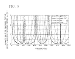
Fig. 8 shows the known relationship between the phase of an incoming wave and the phase of a reflected wave on the opening of a pipe included in an acoustic structure. When an absolute value |m(ζ)| of a specific acoustic impedance ratio ζ at the interface of a medium is zero, a phase difference φ between an incoming wave at the interface of a medium and a reflected wave reflected on the interface of a medium may be equal to ±180° (i.e. their phases are reverse to each other). In the range of |Im(ζ)| <1 (i.e. a graphic region outside a semicircular region with hatching on a Gaussian plane shown inFig. 8 in which Im(ζ) denotes an imaginary part, and Re(ζ) denotes a real part with respect to a specific acoustic impedance ratio ζ), the phase difference φ becomes smaller than ±90°. For this reason, the acoustic structure ofFig. 6 may maximize a sound-absorbing effect and a sound-scattering effect when the absolute value |Im(ζ)| of the imaginary part Im(ζ) of the specific acoustic impedance ratio ζ on the opening of a pipe becomes zero. In contrast, the acoustic structure may not produce a sound-absorbing effect and a sound-scattering effect substantially when the absolute value |Im(ζ)| exceeds "1". According to Equation (3) stipulating the relationship between the specific acoustic impedance ratio ζ and the ratio SO/SP (i.e. the ratio of the area SO of the opening of a pipe to the sectional area Sp of the cavity), it is possible to increase the bandwidth of a band causing a sound-absorbing effect and a sound-scattering effect close to the resonance frequencies fL-n, fR-n (i.e. a band in which the absolute value |Im(ζ)| of the imaginary part Im(ζ) of the specific acoustic impedance ratio ζ becomes less than "1") in response to the ratio SO/SP getting smaller.Fig. 9 shows the result of experiments which the inventor of this application (i.e. the inventor of Patent Literature 1) conducted to evaluate the foregoing behavior of a pipe in an acoustic structure. In experiments, the inventor of this application attempted to evaluate the behavior of a single pipe with dimensions described in Table relating to the length LL of the closed pipe portion CPL, the length LR of the closed pipe portion CPR, and the ratio SO/SP between the area SO of the opening and the sectional area SP of the cavity perpendicular to the opening, thus calculating the absolute, value |Im(ζ)| of the imaginary part Im(ζ) of the specific acoustic impedance ratio ζ at frequencies ranging from 0 Hz to 1,000 Hz.Table LL (mm) LR (mm) SO/SP Graph 300 485 0.25 Solid Line 300 485 1 Dashed Line 300 485 4 Dotted Line - Through comparison between three examples with SO/SP=0.25, SO/SP=1, SO/SP=4 in terms of the bandwidth of a band corresponding to |Im(ζ)| less than "1", an example of SO/SP=0.25 indicates the largest bandwidth while an example with SO/SP=4 indicates the smallest bandwidth. Compared to a pipe with a large ratio SO/SP, a pipe with a small ratio SO/SP is able to produce a sound-absorbing effect and a sound-scattering effect in a wide band. This proves an insight that an acoustic structure including a pipe with the opening area So smaller than the sectional area SP of the cavity is able to improve a sound-absorbing effect and a sound-scattering effect.
- As disclosed in
Patent Literature 1, the bandwidth of a band causing a sound-absorbing effect and a sound-scattering effect with a pipe of an acoustic structure depends on the ratio between the opening area and the sectional area of the cavity of a pipe. However, the conventional acoustic structure is unable to change the ratio between the opening area and the sectional area of the cavity of a pipe; hence, it is impossible to adjust the bandwidth of a band causing a sound-absorbing effect and a sound-scattering effect in an acoustic space (e.g. a sound chamber) equipped with an acoustic structure. -
- Patent Literature 1: Japanese Patent Application Publication No.
2010-84509 - Patent Literature 2: United States Patent Application Publication No.
US 2010/0065369 A1 - Patent Literature 3: European Patent Application Publication No.
EP 2 159 787 A2 - It is an object of the present invention to provide an acoustic structure which is able to adjust the bandwidth of a band causing a sound-absorbing effect and a sound-scattering effect in an acoustic space.
- The present invention is directed to an acoustic structure (e.g. an acoustic tuning panel) including a plurality of boards and a plurality of resonance tubes with a plurality of openings. The openings are formed at different positions on the side faces of the resonance tubes. The acoustic structure allows users to mutually move the resonance tubes so as to independently adjust the opening area of the resonance tube. In other words, it is possible to adjust the ratio of the opening area of the resonance tube to the sectional area of the internal cavity of the resonance tube, thus adjusting the bandwidth of a band causing a sound-absorbing effect and a sound-scattering effect in an acoustic space (e.g. a sound chamber).
- In this connection, one resonance tube may be divided into two tubes, which are combined together with their open ends, and interposed in a pair of boards, wherein it is possible to adjust the opening area by moving two boards close to each other or apart from each other. Alternatively, one board may be divided into two boards, which are combined together with their distal ends, and interposed in a pair of resonance tubes having their openings, wherein it is possible to adjust the total opening area by moving two boards close to each other or apart from each other in connection with the openings of the resonance tubes.
- These and other objects, aspects, and embodiments of the present invention will be described in more detail with reference to the following drawings.
-
Fig. 1A is a front view of an acoustic structure according to a first embodiment of the present invention. -
Fig. 1B is a side view of the acoustic structure viewed in a direction B inFig. 1A . -
Fig. 1C is a cross-sectional view taken along line C-C inFig. 1A . -
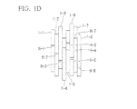
Fig. 1D is a front view of another acoustic structure including a plurality of resonance tubes with adjustable opening areas. -
Fig. 2A is a front view of an acoustic structure according to a second embodiment of the present invention. -
Fig. 2B is a side view of the acoustic structure viewed in a direction B inFig. 2A . -
Fig. 2C is a cross-sectional view taken along line C-C inFig. 2A . -
Fig. 3A is a front view of an acoustic structure according to a third embodiment of the present invention. -
Fig. 3B is a side view of the acoustic structure viewed in a direction B inFig. 3A . -
Fig. 3C is a cross-sectional view taken along line C-C inFig. 3A . -
Fig. 4 is a perspective view of an acoustic structure according to a fourth embodiment of the present invention. -
Fig. 5 is a perspective view showing another example of a resonance tube installed in an acoustic structure. -
Fig. 6 is a front view partly in section showing a conventional acoustic structure. -
Fig. 7 is a longitudinal sectional view of a pipe having an opening, extracted from the acoustic structure ofFig. 6 , which is divided into two closed pipe portions. -
Fig. 8 is a graph showing the relationship between the phase of an incoming wave, entering into the opening of a pipe in an acoustic structure, and a reflected wave reflected on the opening of a pipe. -
Fig. 9 is a graph showing a variation of an absolute value of an imaginary part Im(ζ) of a specific acoustic impedance ratio ζ over frequency in relation to a ratio of an opening area of a pipe to a sectional area of a cavity in pipes with different dimensions. - The present invention will be described in further detail by way of examples with reference to the accompanying drawings.
-
Fig. 1A is a front view of anacoustic structure 10 according to a first embodiment of the present invention.Fig. 1B is a side view of theacoustic structure 10 viewed in a direction B.Fig. 1C is a cross-sectional view taken along line C-C inFig. 1A . As shown inFigs. 1A to 1C , theacoustic structure 10 includes five resonance tubes 1-i (where i= 1 to 5) and six boards 3-i (where i= 1 to 6). In theacoustic structure 10, the resonance tube 1-i includes an internal cavity encompassed by side faces, one of which is equipped with an opening. Theacoustic structure 10 is designed to manually adjust the opening area of the resonance tube 1-i. The resonance tube 1-i is divided into twotubes 2U-i, 2D-i (where i= 1 to 5) each having an open end OE. Each of thetubes 2U-i, 2D-i has a prismatic shape with an open end OE and a closed end CE. The length of thetube 2U-i and the length of thetube 2D-i are differentiated depending on the resonance tube 1-i, but the sum of the lengths of thetubes 2U-i, 2D-i is the same among the resonance tubes 1-i. Specifically, the resonance tube 1-1 includes a length D1U of thetube 2U-1 and a length D1D of thetube 2D-1; the resonance tube 1-2 includes a length D2U of thetube 2U-2 and a length D2D of thetube 2D-2; the resonance tube 1-3 includes a length D3U of thetube 2U-3 and a length D3D of thetube 2D-3; the resonance tube 1-4 includes a length D4U of thetube 2U-4 and a length D4D of thetube 2D-4; the resonance tube 1-5 includes a length D5U of thetube 2U-5 and a length D5D of thetube 2D-5. - In the
acoustic structure 10, the board 3-i (where i= 1 to 6) has a thin rectangular parallelepiped shape with the length identical to the sum of thetubes 2U-i, 2D-i. A pair of the boards 3-i supports the resonance tube 1-i, interposed therebetween, such that the open ends OE of thetubes 2U-i, 2D-i are positioned opposite to each other with a hole H-i (serving as an opening) therebetween and such that thetubes 2U-i, 2D-i can move mutually in an axial direction. - In the
acoustic structure 10, each of thetubes 2U-i, 2D-i included in the resonance tube 1-i has projections XL, XR on the left and right faces thereof, wherein the projections XL, XR are elongated in the length direction of the resonance tube 1-i. Additionally, each of the boards 3-2 to 3-5 has recesses YL, YR on the left and right faces thereof, wherein the recesses YL, YR are elongated in the length direction of the board 3-i. The board 3-1 has a recess YR, elongated in the length direction, on the right face thereof, while the board 3-6 has a recess YL, elongated in the length direction, on the left face thereof. The projections XL, XR formed on the left/right sides of thetubes 2U-i, 2D-i have a trapezoidal shape in cross section with the width gradually increased in a direction departing from the left/right faces as shown inFig. 1B . The recesses YL, YR formed on the left/right sides of the board 3-i have a trapezoidal shape in cross section with the width gradually decreased in a direction approaching to the left/right faces as shown inFig. 1C . In theacoustic structure 10, the projections XL, XR of thetubes 2U-i, 2D-i are engaged with the recesses YR, YL of the boards 3-i, 3-i+ 1 sandwiching the resonance tube 1-i. - The exterior walls of the projections XL of the
tubes 2U-i, 2D-i are brought into contact with the interior walls of the recess YR of the board 3-i via contact friction, while the exterior walls of the projections XR of thetubes 2U-i, 2D-i are brought into contact with the interior walls of the recess YL of the board 3-i via contact friction. The resonance tube 1-i is engaged with the boards 3-i, 3i+1 via the projections XL, XR and the recesses YL, YR such that thetubes 2U-i, 2D-i can slide along the boards 3-i, 3-i+ 1 against contact friction exerted therebetween. By applying force to the resonance tube 1-i in the axial direction, it is possible to collectively move thetubes 2U-i, 2D-i along the boards 3-i, 3i+1 in the axial direction. - The
acoustic structure 10 shown inFigs. 1A to 1C may allow the user to collectively move the five resonance tubes 1-i, sandwiched between the six boards 3-i, in the axial direction, thus adjusting the sizes of the holes H-i; but this is not a restriction.Fig. 1D shows another example of theacoustic structure 10 including eight resonance tubes 1-i (where i= 1 to 8), each of which can be independently adjusted in the length and the size of the hole H-i by appropriately moving thetubes 2U-i, 2D-i in the axial direction. Specifically, the resonance tubes 1-2, 1-4, 1-7 are adjusted to close the holes H-2, H-4, H-7, which are formed at different positions. - The resonance tubes 1-6, 2-8 are adjusted to fully open the holes H-6, H-8, which are formed at different positions. The resonance tubes 1-1, 1-3, 1-5 are adjusted to open the holes H-1, H-3, H-5 halfway, which are formed at different positions. That is, each resonance tube 1-i can be independently adjusted in terms of the length, the position of the hole H-i, and the opening area of the hole H-i. It is possible to selectively adjust the resonance tube 1-i having a desired resonance frequency and to adjust the opening area of the hole H-i, thus achieving a sound-absorbing effect and a sound-scatting effect at a desired band of frequency.
- The first embodiment of the
acoustic structure 10 may produce the outstanding effects as follows. - First, the
acoustic structure 10 of the first embodiment is characterized by using twotubes 2U-i, 2D-i for each resonance tube 1-i, wherein it is possible to increase the opening area of the hole H-i, serving as the opening of the resonance tube 1-i, by moving thetubes 2U-i, 2D-i apart from each other, while it is possible to reduce the opening area of the hole H-i by moving thetubes 2U-i, 2D-i close to each other. Thus, the first embodiment is capable of adjusting the bandwidth of a band causing a sound-absorbing effect and a sound-scattering effect. The first embodiment is capable of adjusting the ratio of the opening area of the resonance tube 1-i to the sectional area of the cavity of the resonance tube 1-i, thus appropriately adjusting the bandwidth of a band causing a sound-absorbing effect and a sound-scattering effect. - Second, the
acoustic structure 10 of the first embodiment is characterized in that the sum of the lengths of thetubes 2U-i, 2D-i is the same among the resonance tubes 1-i. When the resonance tubes 1-i are each shortened such that thetubes 2U-i, 2D-i approach each other and come in contact with each other with their open ends OE, theacoustic structure 10 is entirely formed in a rectangular parallelepiped shape with a large width. Thus, it is possible for users to easily carry theacoustic structure 10 into or out of an acoustic space, and it is possible to easily store theacoustic structure 10 in a storage space. - Third, the
acoustic structure 10 of the first embodiment is characterized in that different lengths are set to thetubes 2U-i, 2D-i among the resonance tubes 1-i. This realizes different resonance frequencies for the resonance tubes 1-i. Thus, it is possible to reduce deviations between bandwidths of bands causing a sound-absorbing effect and a sound-scattering effect. -
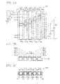
Fig. 2A is a front view of anacoustic structure 10A according to a second embodiment of the present invention.Fig. 2B is a side view of theacoustic structure 10A viewed in a direction B inFig. 2A. Fig. 2C is a cross-sectional view taken along line C-C inFig. 2A . InFigs. 2A, 2B, 2C , parts identical to those shown inFigs. 1A, 1B, 1C are denoted using the same reference signs. For the sake of convenience,Fig. 2B does not include the reference signs of the projections XL, XR and the recesses YL, YR. Compared to theacoustic structure 10 shown inFigs. 1A-1C , theacoustic structure 10A shown inFigs. 2A-2C are equipped with a plurality of sheet members 4-i (where i= 1 to 5) and a plurality ofsupport members 5L-i, 5R- (where i= 1 to 5). The sheet member 4-i is a movable adjuster for shielding the hole H-i, which is formed between the open ends OE of thetubes 2U-i, 2D-i facing each other. Thesupport member 5L-i, 5R-i support the sheet member 4-i to freely move in the axial direction of the resonance tube 1-i. - Specifically, the sheet member 4-i has a square shape whose width is slightly smaller than the widths of the
tubes 2U-i, 2D-i. Thesupport members 5L-i, 5R-i have a rectangular parallelepiped shape whose width is adequately larger than the widths of thetubes 2U-i, 2D-i. - The
support members 5L-i, 5R-i are fixed to the left/right positions on a side face AS of thetube 2D-i such that the left/right ends of the sheet member 4-i are held between thesupport members 5L-i, 5R-i and the side face AS of thetube 2D-i. The left/right ends on the surface and the backside of the sheet member 4-i are engaged with gaps formed between thesupport members 5L-i, 5R-i and the side face AS of thetube 2D-i such that the sheet member 4-i can vertically slide along gaps, formed between thesupport members 5L-i, 5R-i and the side face AS of thetube 2D-i, against contact friction exerted therebetween. With upward force applied to the sheet member 4-i, the sheet member 4-i is moved upwardly in a direction from thetube 2D-i to thetube 2U-i so that the upper portion thereof can be slightly projected above the open end OE of thetube 2D-i. The projected portion of the sheet member 4-i may shield the opening, i.e. the hole H-i formed between the open ends OE of thetubes 2D-i, 2U-i. - The
acoustic structure 10A of the second embodiment is capable of adjusting the opening area of the hole H-i, which is formed between thetubes 2U-i, 2D-i, with the sheet member 4-i which can be moved upwardly/downwardly to shield the opening, i.e. the hole H-i. Thus, it is possible to precisely adjust the bandwidth of a band causing a sound-absorbing effect and a sound-scattering effect. -
Fig. 3A is a front view of anacoustic structure 10B according to a third embodiment of the present invention.Fig. 3B is a side view of theacoustic structure 10A viewed in a direction B inFig. 3A. Fig. 3C is a cross-sectional view taken along line C-C inFig. 3A . Theacoustic structure 10B includes five resonance tubes 6-j (where j= 1 to 5) and four pairs ofboards 8U-j, 8D-j (where j= 1 to 4) which are vertically aligned to adjoin each other. Herein, a pair ofboards 8U-j, 8D-j is held between a pair of resonance tubes 6-j, 6j+1 which are horizontally aligned to adjoin each other. In theacoustic structure 10B, the resonance tube 6-j has three pairs of side faces positioned opposite to each other, i.e. a pair of side faces UW, DW, a pair of side faces FW, BW, and a pair of side faces LW, RW. For the sake of convenience,Fig. 3A does not include the reference signs UW, DW, FW, BW, LW, RW with regard to the resonance tubes 6-2 to 6-5 except for the resonance tube 6-1. All the resonance tubes 6-j have the same length. A pair ofopenings 7L-j, 7R-j is formed on a pair of side faces LW, RW which are positioned opposite to each other in a pair of resonance tubes 6-j which adjoin each other via a pair ofboards 8U-j, 8D-j. Specifically, anopening 7R-1 on the side face RW of the resonance tube 6-1 is positioned opposite to anopening 7L-2 on the side face LW of the resonance tube 6-2 via a pair ofboards 8U-1, 8D-1; anopening 7R-2 on the side face RW of the resonance tube 6-2 is positioned opposite to anopening 7L-3 on the side face LW of the resonance tube 6-3 via a pair ofboards 8U-2, 8D-2; anopening 7R-3 on the side face RW of the resonance tube 6-3 is positioned opposite to anopening 7L-4 on the side face LW of the resonance tube 6-4 via a pair ofboards 8U-3, 8D-3; anopening 7R-4 on the side face RW of the resonance tube 6-4 is positioned opposite to anopening 7L-5 on the side face LW of the resonance tube 6-5 via a pair ofboards 8U-4, 8D-4. - In the
acoustic structure 10B, theboards 8U-j, 8D-j have a thin rectangular parallelepiped shape. A pair ofboards 8U-j, 8D-j which are vertically aligned with a gap Z-j therebetween is interposed between a pair of resonance tubes 6-j, 6j+1 which adjoin each other. Specifically, a pair ofboards 8U-1, 8D-1 which are vertically aligned with a gap Z-1 therebetween is interposed between the side face RW of the resonance tube 6-1 and the side face LW of the resonance tube 6-2. A pair ofboards 8U-2, 8D-2 which are vertically aligned with a gap Z-2 therebetween is interposed between the side face RW of the resonance tube 6-2 and the side face LW of the resonance tube 6-3. A pair ofboards 8U-3, 8D-3 which are vertically aligned with a gap Z-3 therebetween is interposed between the side face RW of the resonance tube 6-3 and the side face LW of the resonance tube 6-4. A pair ofboards 8U-4, 8D-4 which are vertically aligned with a gap Z-4 therebetween is interposed between the side face RW of the resonance tube 6-4 and the side face LW of the resonance tube 6-5. - In the
acoustic structure 10B, a pair ofboards 8U-j, 8D-j is supported by a pair of resonance tubes 6-j, 6-j+ 1 holding a pair ofboards 8U-j, 8D-j therebetween in such a way that a pair ofboards 8U-j, 8D-j can be relatively move along a pair of resonance tubes 6-j, 6-j+1 in the axial direction. For this reason, four pairs of projections XL, XR are formed on the side faces LW, RW of the resonance tubes 6-j, wherein the projections XL, XR are vertically elongated in the length direction of the resonance tube 6-j. Specifically, a projection XR on the side face RW of the resonance tube 6-1 is positioned opposite to a projection XL on the side face LW of the resonance tube 6-2 via a pair ofboards 8U-1, 8D-1; a projection XR on the side face RW of the resonance tube 6-2 is positioned opposite to a projection XL on the side face LW of the resonance tube 6-3 via a pair ofboards 8U-2, 8D-2; a projection XR on the side face RW of the resonance tube 6-3 is positioned opposite to a projection XL on the side face LW of the resonance tube 6-4 via a pair ofboards 8U-3, 8D-3; a projection XR on the side face RW of the resonance tube 6-4 is positioned opposite to a projection XL on the side face LW of the resonance tube 6-5 via a pair ofboards 8U-4, 8D-4. - Additionally, four pairs of recesses YL, YR are formed on the left/right sides of the
boards 8U-j, 8D-j, wherein the recesses YL,YR are elongated in the length direction of theboards 8U-j, 8D-j. The projections XL, XR of the resonance tube 6-j have a trapezoidal shape in cross section with the width gradually increased in a direction departing from the left/right sides of the resonance tube 6-j, while the recesses YL, YR of the boards 8L1-j, 8D-j have a trapezoidal shape in cross section with the width gradually decreased in a direction approaching to the left/right sides of theboards 8U-j, 8D-j. In theacoustic structure 10B, the projection XR of the resonance tube 6-j is engaged with the recess YL of theboards 8U-j, 8D-j, while the projection XL of the resonance tube 6-j+ 1 is engaged with the recess YR of theboards 8U-j, 8D-j. - The exterior walls of the projection XR of the resonance tube 6-j are brought into contact with the interior walls of the recess YL of the
recess 8U-j, 8D-j with contact friction, while the exterior walls of the projection XL of the resonance tube 6-j+ 1 are brought into contact with the interior walls of the recess YR of theboards 8U-j, 8D-j with contact friction. That is, a pair ofboards 8U-j, 8D-j is engaged with a pair of resonance tubes 6-j, 6-j+ 1 via the projections XL, XR and the recesses YL, YR such that a pair ofboards 8U-j, 8D-j can slide along a pair of resonance tubes 6-j, 6-j+ 1 against contact friction exerted therebetween. With upward/downward force applied to a pair ofboards 8U-j, 8D-j, a pair ofboards 8U-j, 8D-j can be moved along the side face RW of the resonance tube 6-j and the side face LW of the resonance tube 6-j+ 1 - In the condition where the
boards 8U-j, 8D-j are moved close to each other, it is possible to completely close theopening 7R-j on the side face RW of the resonance tube 6-j and theopening 7L-j+ 1 on the side face LW of the resonance tube 6-j+1 with theboards 8U-j, 8D-j. By moving theboards 8U-j, 8D-j in the opposite directions, it is possible to form the gap Z-j between theboards 8U-j, 8D-j, and therefore the internal cavities of the resonance tubes 6-j, 6-j+ 1 are able to communicate with the external space via the gap Z-j and theopenings 7R-j, 7L-j+ 1. By increasing the size of the gap Z-j, it is possible to increase the total opening area, i.e. the areas of theopenings 7R-j, 7L-j+ 1 which are not covered with theboards 8U-j, 8D-j. Thus, the third embodiment is able to adjust the bandwidth of a band causing a sound-absorbing effect and a sound-scattering effect. -
Fig. 4 is a perspective view of anacoustic structure 10C according to a fourth embodiment of the present invention. Theacoustic structure 10C includes anacoustic tuning panel 11, asheet member 12, and a windingdevice 13. Theacoustic tuning panel 11 includes five resonance tubes 14-k (where k= 1 to 5), which are horizontally aligned in a direction perpendicular to the length direction with their distal ends uniformly aligned together such that adj acent resonance tubes 14-k, 14-k+ 1 are bonded together. In theacoustic tuning panel 11, the resonance tube 14-k has a prismatic shape. An opening 15-k (where k= 1 to 5) is formed at a predetermined position on the side face of the resonance tube 14-k. Herein, the openings 15-k of the resonance tubes 14-k are formed at different positions in the length direction. The side faces of the resonance tubes 14-k, equipped with the openings 15-k, adjoin together to form auniform baffle surface 16. Thesheet member 12 has a thin rectangular shape, having flexibility, with the same lateral width as theacoustic tuning panel 11 and with the entire length adequately longer than the entire length of theacoustic tuning panel 11. - The winding
device 13 supports thesheet member 12 such that thesheet member 12 can move along thebaffle surface 16 of theacoustic tuning panel 11. Specifically, the windingdevice 13 has a hollow cylindrical shape with the entire lateral width longer than the lateral width of the acoustic tuning panel. Aslit 18 is formed on theperipheral portion 17 of the windingdevice 18. Thesheet member 12 is wound about aninternal shaft 19 of the windingdevice 13. The upper end of thesheet member 12 is pulled upwardly onto thebaffle surface 16 of theacoustic tuning panel 11 via theslit 18 on theperipheral portion 17 of the windingdevice 13. - The
acoustic structure 10C of the fourth embodiment is capable of adjusting the area of the opening 15-k on thebaffle surface 16 of theacoustic tuning panel 11, i.e. the opening area not covered with thesheet member 12 on thebaffle surface 16, by means of the windingdevice 13 which is controlled to increase or decrease the leading part of thesheet member 12 pulled up onto thebaffle surface 16 of theacoustic tuning panel 11. Thus, the fourth embodiment is able to adjust the bandwidth of a band causing a sound-absorbing effect and a sound-scattering effect. - It is possible to further modify the first to fourth embodiments in various ways as follows.
- (1) In the
acoustic structures - (2) In the first and second embodiments, the resonance tube 1-i consists of two
tubes 2U-i, 2D-i which are supported by a pair of boards 3-i, 3-i+1; but this is not a restriction. Instead of the boards 3-i, it is possible to use a single board with the lateral width longer than the sum of the widths of thetubes 2U-i, 2D-i. Herein, a pair oftubes 2U-i, 2D-i forming the resonance tube 1-i may be attached to the surface of a single board with their side faces. In this case, a pair oftubes 2U-i, 2D-i is equipped with a projection elongated on the side faces in the length direction, while five recesses are formed at predetermined positions (corresponding to the positions of the five resonance tubes 1-i) on the surface of a single board. Thus, the projections of the resonance tubes 1-i each consisting of twotubes 2U-i, 2D-i are engaged with the recesses of a single board. - (3) In the first and second embodiments, each of the
tubes 2U-i, 2D-i has an open end OE and a closed end CE; but this is not a restriction. Each of thetubes 2U-i, 2D-i may have one open end OE, while the other ends of each of thetubes 2U-i, 2D-i may have an open end OE. - (4) The
acoustic structures acoustic structure 10B of the third embodiment is configured of five resonance tubes 6-i (where i= 1 to 5); but this is not a restriction. It is possible to change the number of resonance tubes included in each acoustic structure to less than five (i.e. two to four) or greater than five (i.e. six or more). - (5) In the
acoustic structure 10A of the second embodiment, the opening area of the hole H-i, formed between thetubes 2U-i, 2D-i in the resonance tube 1-i, is adjusted with the sheet member 4-i, which can be replaced with another board member. That is, it is possible to cover the hole H-i of the resonance tube 1-i with a board member instead of the sheet member 4-i. - (6) In the
acoustic structure 10 of the first embodiment, the resonance tube 1-i consists of twotubes 2U-i, 2D-i having the same size of the cross section; but this is not a restriction. It is possible to form the resonance tube 1-i by use of thetubes 2U-i, 2D-i having different sizes of cross sections. When the cross section of thetube 2U-i is larger than the cross section of thetube 2D-i, for example, it is possible to partially insert thetube 2D-i into thetube 2U-i in a retractable manner. In this case, it is possible to employ a resonance tube 1-1 consisting of twotubes 2U-1, 2D-1 as shown inFig. 5 . Herein, a cutout NT is formed on the open end OE of thetube 2U-1/2D-1. Thus, it is possible to produce an acoustic structure including a plurality of resonance tubes I-i (each corresponding to the resonance tube 1-1 shown inFig. 5 ), which are horizontally aligned in a direction perpendicular to the length direction of the resonance tube 1-i. - (7) The
acoustic structure 10B of the third embodiment includes a plurality of resonance tubes 6-j equipped with theopenings 7L-j, 7R-j on the side faces LW, RW, wherein a pair ofopenings 7R-j, 7L-j+ 1 is formed on the side faces RW, LW of the adjacent resonance tubes 6-j, 6-j+ 1 which are positioned opposite to each other; but this is not a restriction. It is possible to form a single opening on the side face LW/RW of each resonance tube 6-j, specifically each of the resonance tubes 6-2 to 6-4 which adjoin each other. - Lastly, the present invention is not necessarily limited to the first to fourth embodiments and their variations, which are illustrative and not restrictive, since the present invention should fall within the scope of the invention defined by the appended claims. In particular, the features of all dependent claims and all embodiments can be combined with each other, as long as they do not contradict each other.
Claims (6)
- An acoustic structure comprising:a plurality of resonance tubes; anda plurality of openings formed on side faces of the resonance tubes at prescribed positions; andat least one adjuster adjusting an opening area of the opening formed on the side faces of the plurality of resonance tubes.
- The acoustic structure according to claim 1, further comprising:a plurality of boards supporting the plurality of resonance tubes,wherein each of the resonance tubes is divided into two tubes which are combined together with open ends positioned opposite to each other, andwherein the two tubes forming each of the resonance tubes are movable independently in an axial direction along a pair of the boards interposing the resonance tube therebetween, thus adjusting the opening area of the opening of the resonance tube.
- The acoustic structure according to claim 1, further comprising:a plurality of adjusters which are independently movable to shield at least part of the plurality of openings formed in the plurality of resonance tubes while the plurality of resonance tubes are mutually moved in the axial direction, thus adjusting the opening area of the openings of the resonance tubes.
- The acoustic structure according to claim 1, further comprising:a plurality of boards supporting the plurality of resonance tubes,wherein each of the boards is divided into two boards which are combined together with distal ends positioned opposite to each other,wherein the plurality of openings are formed on predetermined side faces of the resonance tubes which are positioned opposite to each other when the plurality of resonance tubes are combined together, andwherein the two boards are interposed between a pair of resonance tubes and independently movable in an axial direction so as to adjust the opening area of the opening of the pair of resonance tubes.
- The acoustic structure according to claim 1, further comprising:a sheet member, corresponding to the at least one adjuster, which is movable along a baffle surface formed by the side faces of the plurality of resonance tubes combined together,wherein the plurality of openings is exposed on the side faces of the plurality of resonance tubes forming the baffle surface, andwherein the sheet member is movable along the baffle surface to shield at least part of the plurality of openings exposed on the baffle surface.
- The acoustic structure according to claim 1, wherein the at least one adjuster adjusts a ratio of the opening area of the openings of the resonance tubes to a sectional area of internal cavities of the resonance tubes.
Applications Claiming Priority (1)
| Application Number | Priority Date | Filing Date | Title |
|---|---|---|---|
| JP2011254633A JP5834816B2 (en) | 2011-11-22 | 2011-11-22 | Acoustic structure |
Publications (1)
| Publication Number | Publication Date |
|---|---|
| EP2597637A1 true EP2597637A1 (en) | 2013-05-29 |
Family
ID=47257514
Family Applications (1)
| Application Number | Title | Priority Date | Filing Date |
|---|---|---|---|
| EP12193211.5A Withdrawn EP2597637A1 (en) | 2011-11-22 | 2012-11-19 | Acoustic structure |
Country Status (4)
| Country | Link |
|---|---|
| US (1) | US8714303B2 (en) |
| EP (1) | EP2597637A1 (en) |
| JP (1) | JP5834816B2 (en) |
| CN (1) | CN103137120B (en) |
Families Citing this family (15)
| Publication number | Priority date | Publication date | Assignee | Title |
|---|---|---|---|---|
| US9607600B2 (en) | 2009-02-06 | 2017-03-28 | Sonobex Limited | Attenuators, arrangements of attenuators, acoustic barriers and methods for constructing acoustic barriers |
| WO2014207838A1 (en) * | 2013-06-26 | 2014-12-31 | ヤマハ株式会社 | Musical instrument and part for musical instrument |
| JP2015184524A (en) * | 2014-03-25 | 2015-10-22 | ヤマハ株式会社 | acoustic structure |
| GB201415874D0 (en) * | 2014-09-08 | 2014-10-22 | Sonobex Ltd | Acoustic Attenuator |
| JP6625227B2 (en) * | 2016-08-31 | 2019-12-25 | 富士フイルム株式会社 | Soundproof structure and soundproof system |
| CN109690669B (en) * | 2016-09-13 | 2020-06-19 | 富士胶片株式会社 | Soundproof structure and soundproof system |
| US10722990B2 (en) | 2016-09-15 | 2020-07-28 | General Electric Company | Method for installing and removing modularized silencer baffles |
| JP6610506B2 (en) * | 2016-11-07 | 2019-11-27 | ヤマハ株式会社 | Sound equipment |
| CN108278157B (en) | 2017-01-06 | 2022-08-02 | 通用电气公司 | System and method for improved inlet silencer baffle |
| CN108278158B (en) * | 2017-01-06 | 2022-05-13 | 通用电气公司 | System and method for improved inlet muffling baffle |
| US11776522B2 (en) * | 2020-11-12 | 2023-10-03 | Toyota Motor Engineering & Manufacturing North America, Inc. | Sound isolating wall assembly having at least one acoustic scatterer |
| US11776521B2 (en) * | 2020-12-11 | 2023-10-03 | Toyota Motor Engineering & Manufacturing North America, Inc. | Sound absorbing structure having one or more acoustic scatterers attached to or forming a vehicle structure |
| CN114165481A (en) * | 2021-09-13 | 2022-03-11 | 荣耀终端有限公司 | Fan device and electronic equipment |
| JP7461978B2 (en) * | 2022-02-25 | 2024-04-04 | 本田技研工業株式会社 | Sound absorbing device for moving objects |
| US12589411B2 (en) * | 2023-08-22 | 2026-03-31 | Toyota Motor Engineering & Manufacturing North America, Inc. | Systems for absorbing flexural waves acting upon a structure using monopole and dipole resonance |
Citations (9)
| Publication number | Priority date | Publication date | Assignee | Title |
|---|---|---|---|---|
| JPH09213541A (en) * | 1996-02-05 | 1997-08-15 | Mitsubishi Electric Corp | Soundproofing device and transformer using the same |
| US20020017426A1 (en) * | 2000-07-13 | 2002-02-14 | Yamaha Corporation | Sound radiating structure, acoustic room and sound scattering method |
| JP2003328326A (en) * | 2002-05-14 | 2003-11-19 | Unipres Corp | Soundproofing |
| JP2005207250A (en) * | 2004-01-20 | 2005-08-04 | Calsonic Kansei Corp | Silencer using multiplex pipe |
| JP2005282321A (en) * | 2004-03-31 | 2005-10-13 | Kobe Steel Ltd | Floor structure |
| US20060059801A1 (en) * | 2004-09-15 | 2006-03-23 | Quality Research Development & Consulting, Inc. | Acoustically intelligent structures with resonators |
| EP2159787A2 (en) | 2008-09-02 | 2010-03-03 | Yamaha Corporation | Acoustic structure and acoustic room |
| US20100078258A1 (en) * | 2008-09-30 | 2010-04-01 | Hitachi, Ltd. | Silencing equipment for electric devices |
| US20110278091A1 (en) * | 2010-05-17 | 2011-11-17 | Yamaha Corporation | Acoustic Structure |
Family Cites Families (8)
| Publication number | Priority date | Publication date | Assignee | Title |
|---|---|---|---|---|
| US4231447A (en) * | 1978-04-29 | 1980-11-04 | Rolls-Royce Limited | Multi-layer acoustic linings |
| US5930371A (en) * | 1997-01-07 | 1999-07-27 | Nelson Industries, Inc. | Tunable acoustic system |
| DE10026121A1 (en) * | 2000-05-26 | 2001-11-29 | Alstom Power Nv | Device for damping acoustic vibrations in a combustion chamber |
| US6698390B1 (en) * | 2003-01-24 | 2004-03-02 | Visteon Global Technologies, Inc. | Variable tuned telescoping resonator |
| US6792907B1 (en) * | 2003-03-04 | 2004-09-21 | Visteon Global Technologies, Inc. | Helmholtz resonator |
| US20050098379A1 (en) * | 2003-10-09 | 2005-05-12 | Takahiko Sato | Noise absorbing structure and noise absorbing/insulating structure |
| US7089901B2 (en) * | 2004-03-30 | 2006-08-15 | Toyoda Gosei Co., Ltd. | Resonator |
| KR100859905B1 (en) * | 2005-12-13 | 2008-09-23 | 야마하 가부시키가이샤 | Keyboard-type tone plate percussion instrument and resonance tube and resonance box for tone plate percussion instrument |
-
2011
- 2011-11-22 JP JP2011254633A patent/JP5834816B2/en not_active Expired - Fee Related
-
2012
- 2012-11-16 US US13/679,621 patent/US8714303B2/en not_active Expired - Fee Related
- 2012-11-19 EP EP12193211.5A patent/EP2597637A1/en not_active Withdrawn
- 2012-11-20 CN CN201210472606.6A patent/CN103137120B/en not_active Expired - Fee Related
Patent Citations (11)
| Publication number | Priority date | Publication date | Assignee | Title |
|---|---|---|---|---|
| JPH09213541A (en) * | 1996-02-05 | 1997-08-15 | Mitsubishi Electric Corp | Soundproofing device and transformer using the same |
| US20020017426A1 (en) * | 2000-07-13 | 2002-02-14 | Yamaha Corporation | Sound radiating structure, acoustic room and sound scattering method |
| JP2003328326A (en) * | 2002-05-14 | 2003-11-19 | Unipres Corp | Soundproofing |
| JP2005207250A (en) * | 2004-01-20 | 2005-08-04 | Calsonic Kansei Corp | Silencer using multiplex pipe |
| JP2005282321A (en) * | 2004-03-31 | 2005-10-13 | Kobe Steel Ltd | Floor structure |
| US20060059801A1 (en) * | 2004-09-15 | 2006-03-23 | Quality Research Development & Consulting, Inc. | Acoustically intelligent structures with resonators |
| EP2159787A2 (en) | 2008-09-02 | 2010-03-03 | Yamaha Corporation | Acoustic structure and acoustic room |
| US20100065369A1 (en) | 2008-09-02 | 2010-03-18 | Yamaha Corporation | Acoustic structure and acoustic room |
| JP2010084509A (en) | 2008-09-02 | 2010-04-15 | Yamaha Corp | Acoustic structure and acoustic room |
| US20100078258A1 (en) * | 2008-09-30 | 2010-04-01 | Hitachi, Ltd. | Silencing equipment for electric devices |
| US20110278091A1 (en) * | 2010-05-17 | 2011-11-17 | Yamaha Corporation | Acoustic Structure |
Also Published As
| Publication number | Publication date |
|---|---|
| JP5834816B2 (en) | 2015-12-24 |
| CN103137120B (en) | 2016-01-27 |
| US8714303B2 (en) | 2014-05-06 |
| JP2013109189A (en) | 2013-06-06 |
| US20130126268A1 (en) | 2013-05-23 |
| CN103137120A (en) | 2013-06-05 |
Similar Documents
| Publication | Publication Date | Title |
|---|---|---|
| US8714303B2 (en) | Acoustic structure | |
| US9282398B2 (en) | Speaker system having wide bandwidth and wide high-frequency dispersion | |
| EP3041265B1 (en) | Loudspeaker with improved directional behavior and reduction of acoustical interference | |
| EP3058751B1 (en) | Planar magnetic transducer | |
| US20100092019A1 (en) | Waveguide electroacoustical transducing | |
| JP2018053708A (en) | Sound insulation louver | |
| CN108391210B (en) | speaker equipment | |
| US8422712B2 (en) | Horn-loaded acoustic source with custom amplitude distribution | |
| JP6914004B2 (en) | Noise reduction device | |
| JP2018506738A (en) | Panel for noise suppression | |
| US20190253792A1 (en) | Acoustic lens and speaker system | |
| US10602263B2 (en) | Planar loudspeaker manifold for improved sound dispersion | |
| JP2023029654A (en) | speaker system | |
| JP2017101530A (en) | Noise reduction structure | |
| US10720136B2 (en) | Layered chamber acoustic attenuation | |
| FI110896B (en) | Sound active damping construction | |
| WO2015161891A1 (en) | Acoustical waveguide | |
| JP7628143B2 (en) | Waveguide connection structure and waveguide switch using the same | |
| US7991170B2 (en) | Loudspeaker crossover filter | |
| JP2017073635A (en) | Frequency selectivity radio wave transmission prevention plate, frequency selectivity radio wave transmission device applied with the same and method for the same | |
| JP2018053463A (en) | Double skin structure | |
| JPS6354898A (en) | Speaker system | |
| JP2001274606A (en) | Variable electromagnetic wave filter using passage | |
| WO2016113692A1 (en) | Three-way loudspeaker system with column for subwoofer | |
| JP2025144281A (en) | sound-absorbing structure |
Legal Events
| Date | Code | Title | Description |
|---|---|---|---|
| PUAI | Public reference made under article 153(3) epc to a published international application that has entered the european phase |
Free format text: ORIGINAL CODE: 0009012 |
|
| AK | Designated contracting states |
Kind code of ref document: A1 Designated state(s): AL AT BE BG CH CY CZ DE DK EE ES FI FR GB GR HR HU IE IS IT LI LT LU LV MC MK MT NL NO PL PT RO RS SE SI SK SM TR |
|
| AX | Request for extension of the european patent |
Extension state: BA ME |
|
| 17P | Request for examination filed |
Effective date: 20130924 |
|
| RBV | Designated contracting states (corrected) |
Designated state(s): AL AT BE BG CH CY CZ DE DK EE ES FI FR GB GR HR HU IE IS IT LI LT LU LV MC MK MT NL NO PL PT RO RS SE SI SK SM TR |
|
| STAA | Information on the status of an ep patent application or granted ep patent |
Free format text: STATUS: THE APPLICATION HAS BEEN WITHDRAWN |
|
| 18W | Application withdrawn |
Effective date: 20180301 |