EP2597559A2 - Information Processing Apparatus and Information Processing Method to Realize Input Means Having High Operability - Google Patents
Information Processing Apparatus and Information Processing Method to Realize Input Means Having High Operability Download PDFInfo
- Publication number
- EP2597559A2 EP2597559A2 EP12191883.3A EP12191883A EP2597559A2 EP 2597559 A2 EP2597559 A2 EP 2597559A2 EP 12191883 A EP12191883 A EP 12191883A EP 2597559 A2 EP2597559 A2 EP 2597559A2
- Authority
- EP
- European Patent Office
- Prior art keywords
- guis
- gui
- information processing
- locations
- display
- Prior art date
- Legal status (The legal status is an assumption and is not a legal conclusion. Google has not performed a legal analysis and makes no representation as to the accuracy of the status listed.)
- Granted
Links
Images

Classifications
-
- G—PHYSICS
- G06—COMPUTING OR CALCULATING; COUNTING
- G06F—ELECTRIC DIGITAL DATA PROCESSING
- G06F3/00—Input arrangements for transferring data to be processed into a form capable of being handled by the computer; Output arrangements for transferring data from processing unit to output unit, e.g. interface arrangements
- G06F3/01—Input arrangements or combined input and output arrangements for interaction between user and computer
- G06F3/048—Interaction techniques based on graphical user interfaces [GUI]
- G06F3/0487—Interaction techniques based on graphical user interfaces [GUI] using specific features provided by the input device, e.g. functions controlled by the rotation of a mouse with dual sensing arrangements, or of the nature of the input device, e.g. tap gestures based on pressure sensed by a digitiser
- G06F3/0488—Interaction techniques based on graphical user interfaces [GUI] using specific features provided by the input device, e.g. functions controlled by the rotation of a mouse with dual sensing arrangements, or of the nature of the input device, e.g. tap gestures based on pressure sensed by a digitiser using a touch-screen or digitiser, e.g. input of commands through traced gestures
-
- A—HUMAN NECESSITIES
- A63—SPORTS; GAMES; AMUSEMENTS
- A63F—CARD, BOARD, OR ROULETTE GAMES; INDOOR GAMES USING SMALL MOVING PLAYING BODIES; VIDEO GAMES; GAMES NOT OTHERWISE PROVIDED FOR
- A63F13/00—Video games, i.e. games using an electronically generated display having two or more dimensions
- A63F13/20—Input arrangements for video game devices
- A63F13/21—Input arrangements for video game devices characterised by their sensors, purposes or types
- A63F13/214—Input arrangements for video game devices characterised by their sensors, purposes or types for locating contacts on a surface, e.g. floor mats or touch pads
- A63F13/2145—Input arrangements for video game devices characterised by their sensors, purposes or types for locating contacts on a surface, e.g. floor mats or touch pads the surface being also a display device, e.g. touch screens
-
- A—HUMAN NECESSITIES
- A63—SPORTS; GAMES; AMUSEMENTS
- A63F—CARD, BOARD, OR ROULETTE GAMES; INDOOR GAMES USING SMALL MOVING PLAYING BODIES; VIDEO GAMES; GAMES NOT OTHERWISE PROVIDED FOR
- A63F13/00—Video games, i.e. games using an electronically generated display having two or more dimensions
- A63F13/60—Generating or modifying game content before or while executing the game program, e.g. authoring tools specially adapted for game development or game-integrated level editor
- A63F13/67—Generating or modifying game content before or while executing the game program, e.g. authoring tools specially adapted for game development or game-integrated level editor adaptively or by learning from player actions, e.g. skill level adjustment or by storing successful combat sequences for re-use
-
- G—PHYSICS
- G06—COMPUTING OR CALCULATING; COUNTING
- G06F—ELECTRIC DIGITAL DATA PROCESSING
- G06F3/00—Input arrangements for transferring data to be processed into a form capable of being handled by the computer; Output arrangements for transferring data from processing unit to output unit, e.g. interface arrangements
- G06F3/01—Input arrangements or combined input and output arrangements for interaction between user and computer
- G06F3/03—Arrangements for converting the position or the displacement of a member into a coded form
- G06F3/041—Digitisers, e.g. for touch screens or touch pads, characterised by the transducing means
- G06F3/0416—Control or interface arrangements specially adapted for digitisers
- G06F3/0418—Control or interface arrangements specially adapted for digitisers for error correction or compensation, e.g. based on parallax, calibration or alignment
- G06F3/04186—Touch location disambiguation
-
- G—PHYSICS
- G06—COMPUTING OR CALCULATING; COUNTING
- G06F—ELECTRIC DIGITAL DATA PROCESSING
- G06F3/00—Input arrangements for transferring data to be processed into a form capable of being handled by the computer; Output arrangements for transferring data from processing unit to output unit, e.g. interface arrangements
- G06F3/01—Input arrangements or combined input and output arrangements for interaction between user and computer
- G06F3/048—Interaction techniques based on graphical user interfaces [GUI]
- G06F3/0484—Interaction techniques based on graphical user interfaces [GUI] for the control of specific functions or operations, e.g. selecting or manipulating an object, an image or a displayed text element, setting a parameter value or selecting a range
- G06F3/04842—Selection of displayed objects or displayed text elements
Definitions
- the present invention relates to an information processing apparatus, for example (though not exclusively) for processing information and simultaneously displaying the resulting images, as well as an information processing method employed by the information processing apparatus.
- a device capable of displaying and being input information thereon in the same region by placing a touch panel over a display has been commonly used in recent years. Provision of the touch panel like this allows the selection and movement of subjects such as icons and the enlargement/reduction, scrolling, and page turning of a display screen image on a web page or document to be conducted as if an actual thing exists before the user even though those objects, documents and the like are merely present in the two-dimensional plane. Hence, this permits intuitive responses and operations.
- the present invention has been made in view of these problems, and a purpose of at least embodiments thereof is to provide a technology for realizing input means having high operability even when highly sophisticated information is required to be displayed.
- the information processing apparatus includes: an operating information acquiring unit configured to acquire information regarding a specific position, inputted by a user, in a display image and configured to detect in the display image a graphical user interface (GUI) located within a predetermined range from the specific position; a GUI location control unit configured to vary the locations of a plurality of GUIs on the display image, when the plurality of GUIs are detected by the operating information acquiring unit; and an information processing unit configured to perform information processing corresponding to a GUI, according to a user's operation on said GUI whose location has been varied.
- GUI graphical user interface
- the information processing method includes: acquiring information regarding a specific position, inputted by a user, in a display image and detecting in the display image a graphical user interface (GUI) located within a predetermined range from the specific position; and varying the locations of a plurality of GUIs on the display image when the plurality of GUIs are detected, and displaying the GUIs at the varied locations on a display.
- GUI graphical user interface
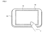
- FIG. 1 illustrates an example of the appearance of an information processing apparatus according to an embodiment of the present invention.
- the information processing apparatus may be any one of a mobile phone, a portable digital assistant (PDA), a mobile game device, a tablet terminal, and the like that are each provided with a display function and the other information processing functions in an integrated fashion.
- a device having the appearance like that of the information processing apparatus 10 as shown in FIG. 1 may be a unit used for display and input purposes, and the remaining information processing functions may be provided in a separate casing that connects to said unit.
- the information processing apparatus 10 may be provided with various types of mechanism and components according to the functions. Since a known art may be used for such mechanisms and components, the description thereof will be omitted as appropriate.
- the information processing apparatus 10 is structured such that the a display 14 is placed in from of the body of the information processing apparatus 10 and the top surface is covered with a touch panel 12.
- the components required for various information processings such as a CPU, a graphics processor, an audio processor, and a memory (all of which are not shown in FIG. 1 ) are incorporated into the back side of the display 14.
- the display 14 may be any one of a liquid crystal display, an electro luminescent display (ELD), a plasma display and the like which are commonly used today.
- the touch panel 12 may implement any of a resistive overlay method, an optical method, an electrostatic capacitance coupling method, and the like which are in practical use.
- the touch panel detects a contact point by a finger 7.
- the information processing apparatus 10 may further comprise a speaker for outputting audio, an earphone connection terminal, an infrared port or wireless LAN (Local Area Network) feature used to communicate with other devices, a battery box, and the like all of which are omitted in FIG. 1 .
- the display 14 displays a menu screen or a screen including an icon for the input of a user's operation, a game screen, a moving-image playback screen, a text display screen, a still-image display screen or the like which indicates the results of information processings, according to the functions of the information processing apparatus 10.
- FIG. 2 illustrates a detailed structure of an information processing apparatus 10.
- the information processing apparatus 10 includes a content file storage 16 for storing programs and various data for contents, an input/output (I/O) control unit 20 for controlling the receiving of signals inputted from the touch panel 12 and the output of image data to the display 14, an operating information conversion unit 22 for converting an input signal from the touch panel 12 into information regarding an operation input, a content processing unit 24 for processing a content according to the operation input, a GUI location control unit 26 for controlling the location of a GUI according to the contact point, and a display image generator 30 for generating a display image.
- I/O input/output
- the structural components described as functional blocks that perform various processings may be implemented hardware-wise by elements such as a CPU (Central Processing Unit), memory and other LSIs, and software-wise by image processing programs or the like. Therefore, it will be obvious to those skilled in the art that the functional blocks may be implemented by a variety of manners including hardware only, software only or a combination of both and should not be considered as limiting.
- a CPU Central Processing Unit
- memory and other LSIs
- image processing programs or the like may be implemented by a variety of manners including hardware only, software only or a combination of both and should not be considered as limiting.
- the input/output control unit 20 connects to the touch panel 12 and the display 14 and controls the input/output of data using a commonly-used method.
- the input signal received from the touch panel 12 indicates the coordinates of a contact point at which the user touches on the touch panel 12, a movement (travel) path of the coordinates when the contact point moves continuously, and the like.
- a method for detecting the contact point on the touch panel 12 differs depending on the employed detecting system and therefore the description thereof is not given here.
- the input/output control unit 20 also outputs a video signal for a displayed image to the display 14.
- the content file storage 16 stores various types of data required for carrying out the information processing regarding the displaying of content according to the user's operation by using the touch panel.
- the "content” as used herein may be computer games, movies, music, novels, photographs, maps, web pages, and so forth; the types thereof and the path through which data is stored are not limited to any specific ones so long as the subjects thereof can be expressed after electronic processing.
- the embodiments of the invention can be applied not only to general “content” but also to the general information processing for communications, schedule management, address list, spreadsheet, and the like. In the following description, all of general "content” together with such entities will be collectively referred to as the "content”.
- the content file storage 16 stores the program for the game, information on a player or players, information on the achievement level (score) attained at the previous game play, and so forth.
- the content file storage 16 stores video data or audio data that has been compressed and coded, a program used to decode and playback the video data or audio data, and so forth.
- the content file storage 16 may be a hard disk drive or a combination of a removable recording medium (e.g., memory card, ROM disk, optical disk or magneto-optical disk) and a readout system compatible with the removable recording medium.
- the operating information conversion unit 22 acquires from the input/output control unit 20 an input signal fed from the touch panel 12 and identifies the operation input intended by the user based on the coordinates of a contact point contained in the input signal. If, for example, a GUI (Graphical User Interface) is displayed in a screen as an on-screen display, an operation input corresponding to the GUI which is a target of a touch will be identified based on the correspondence relation between the coordinates of the contact point and the GUI position, and then convey the thus identified operation input to the content processing unit 24.
- GUI Graphic User Interface
- the operating information conversion unit 22 will first inform the GUI location control unit 26 of the presence of the GUIs. If, for example, a selection input is to be received in such a manner that a plurality of locations in a virtual world, a map, a three-dimensional object and the like displayed on the display 14 are indicated by their respective icons as options, the icons may be too closely located to each other depending on the scale of the image or the location of a viewpoint.
- the operating information conversion unit 22 recognizes that this particular GUI is operated and effected. Then the operating information conversion unit 22 conveys the corresponding operation input to the content processing unit 24. Then the operating information conversion unit 22 also detects that the location of GUIs whose distances therebetween have returned to the original (initial) positions, and conveys the thus detected result to the GUI location control unit 26.
- the content processing unit 24 performs processings necessary for the progress of a game and the displaying of various content items according to the operation input, using programs and image data stored in the content file storage 16. At this time, the GUIs such as icons indicating the options available are displayed according to the setting in a content file in such a manner that the GUIs are superposed on a content image.
- a known art appropriate to the content creator's intention may be used for the GUI rendering process performed by the content processing unit 24.
- the GUI location control unit 26 varies the arrangement of GUIs in such a manner as to widen the space between the GUIs and restore the GUIs to the their original positions according to the notification sent from the operating information conversion unit 22.
- the space therebetween is to be widened, the positional information on the contact point, the identification information and the positional information on a plurality of GUIs whose positions are to be varied are received from the operating information conversion unit 22.
- the identification information on the GUIs is associated with the images of the GUIs in the content file stored in the content file storage 16.
- the GUI location control unit 26 determines the positions of the respective GUIs, whose arrangement have been changed, based on the position of the contact point and conveys the thus determined positions thereof to the display image generator 30 in association with the identification information on the GUIs.
- the arrangement of the GUIs is to be restored to the original (initial) arrangement
- the positional information on the original positions of the respective GUIs temporarily stored in an internal memory or the like is conveyed to the display image generator 30 in association with the identification information of the GUIs.
- the GUI location control unit 26 also coveys the identification information on the respective GUIs and the positional information on the GUIs after the change, to the operating information conversion unit 22.
- the operating information conversion unit 22 updates the positional information on the GUIs stored therein to the latest one, identifies a GUI associated with the contact point and eventually identifies the content input with accuracy.
- the display image generator 30 generates image data to be outputted, in response to a request sent from the content processing unit 24 or the GUI location control unit 26 and outputs the image data to the input/output control unit 20.
- the image generated by the display image generator 30 is an image to be newly displayed as a result of the processing by the content processing unit 24 or an image for which the GUI is placed in the position specified by the GUI location control unit 26.
- the display image generator 30 renders a new image by, for example, reading out necessary image data from the content file storage 16 according to an instruction given from the content processing unit 24.
- the display image generator 30 reads out image data of a GUI associated with the identification information conveyed from the GUI location control unit 26, from the content file storage 16 and renders images where the GUI moves to a specified position.
- the image thus generated is stored in a frame buffer in the input/output control unit 20 and is displayed on the display 14 when the image is outputted to the display 14, with the suitable timing, from the input/output control unit 20.
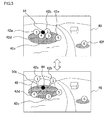
- FIG. 3 illustrates an exemplary display images before and after a change of locations of GUIs.
- an image 40 displayed on the display 14, which expresses a virtual world, for instance, is first displayed as a result of information processing performed by the content processing unit 24 according to a content item.
- the locations where items are selectable are indicated by six icons 42a, 42b, 42c, 42d, 42e, and 42f.
- graphics marked with the encircled numbers "1" to "6" are the icons 42a, 42b, 42c, 42d, 42e, and 42f, respectively
- the information and shape displayed as the icons are not limited to any particular ones and may be determined as appropriate at the time of content preparation.
- the image of an item to be selected may be mimicked and used directly as an icon. Or the name thereof may be displayed as textual information.
- the GUI is not limited to the icon with which to select an item.
- the types of the GUI is not limited to any particular ones so long as it is an image indicating an option to receive the selection input through the user's contact.
- the GUI may be icons, buttons and the like with which to select a function or file provided by the information processing apparatus 10..
- the operating information conversion unit 22 determines whether there are plurality of icons in a predetermined range from the contact point 44 or not. Assume, for example, in FIG. 4 that the four icons 42a, 42b, 42c and 42d marked with "1" to "4", respectively, are located within the predetermined range. Then, the arrangement of the four icons 42a, 42b, 42c and 42d is varied such that the spaces between the four icons are enlarged, under the control of the GUI location control unit 26. Image 46 of FIG. 4 illustrates the arrangement thereof after the spaces therebetween have been widened. It is appreciated here that the "predetermined range" serving as a decision criterion based on which the arrangement thereof is varied may differ for each icon. Concrete examples will be discussed later.
- the four icons 42a, 42b, 42c and 42d are placed on a circle, having a predetermined radius, at equal spaces therebetween wherein the center of the contact point 33 is at the center of the circle. That is, N icons are placed in the N respective positions where the circle 48 is divided into N equal parts.
- a pointer graphic such as a pointer graphic 50a for the icon 42a, which points toward the original position of each icon in the original (initial) image 40 is attached to each icon.
- the pointer graphic may be of any arbitrary form, such as arrow, straight line and curved line, so long as the point graphic can associate the icon with its original position.
- Each icon is preferably placed in a position near its original position in order that the pointer graphic does not intersect or overlap with the other ones.
- a transition stage from the image 40 to the image 46 may be expressed by actions, such as an animation, where the pointer graphic expands while each icon is moving.
- a touch for the contact point in the original image 40 may be a "touch" in a general sense such as a contact with the touch panel 12 for a short time, and the user may release his/her finger in the image 46 at the time when the image 46 after the change is displayed.
- the black circle representing the contact point 44 and the circle 48 depicted in FIG. 3 are for illustration purposes only and are not necessarily displayed on the screen (or even does not have to be displayed at all in the actual setting).
- the image may be processed such that the contact point 44 and the circle 48 can be viewed or visually recognized for the purpose of rendering a special effect or the like.
- the icons selectable are limited to only the icons 42a, 42b, 42c and 42d whose locations have been moved, the following special rendering may be performed in order to make these four icons far more conspicuous than the other icons and images. That is, a region surrounded by the circle 48 or a band-like region with the circle 48 as the center curved line is subjected to shading-off effect or is filled with a single color. A line, a rectangle, a polygon, a shape resembling a symbol of some sort, and the like may be used in place of the circle 48.
- the size of the circle 48 may be adaptively varied such that, for example, the greater the number of icons whose locations are to be changed is, the larger the size of the circle 48 will be.
- the operating information conversion unit 22 recognizes that the icon has been selected and identifies the operation input corresponding to the selected icon, and thereby the content processing unit 24 performs the information processing as appropriate. For example, an item represented by the selected icon is zoomed up; the content of a file associated with the icon is displayed; or another program associated with the icon is started. An operation on the icon selected may be performed at once such that the contact point is moved continuously from a starting point to an ending point.
- the starting point corresponds to the touch of the contact point 44 in the image 40
- the ending point correspond to the touch of a desired icon in the image 46 after the change.
- the user touches a predetermined region other than the icons located on the circle 48 e.g., a region outside the circle 48
- the icons whose locations have been changed are restored to the original positions under the control of the GUI location control unit 26 and thereby the image 40 is displayed again.
- a graphic or figure may be displayed so that the original position of the contact point 44 can be viewed and thereby the contact on this graphic may work to restore the locations of icons to the original positions thereof.
- any of the icons located outside the circuit 48 may also be selected.
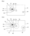
- FIG. 4 is a diagram to explain a method whereby an operating information conversion unit determines whether the locations of a plurality of icons are to be varied or not.
- a rectangle 60 represents a screen plane, and it is assumed that the six icons 42a, 42b, 42c, 42d, 42e, and 42f as shown in FIG. 3 are arranged similarly.
- the operating information conversion unit 22 constantly acquires the positional coordinates of each icon in a screen coordinate system determined by the content processing unit 24 through a process concerning the displaying of content.
- the operating information conversion unit 22 converts the positional information thereon into the positional coordinates in the screen coordinate system.
- the icons 42a, 42b, 42c, 42d, 42e, and 42f and the contact point 44 are expressed as circles, the information stored in the operating information conversion unit 22 is the coordinates of the centers, for instance.
- a circular decision region 62 having a predetermined radius with the coordinates of the contact point 44 located at the center of the circular decision region is set, and an icon or icons whose positional coordinates lie within the decision region 62 is/are detected. That is, detected is/are an icon or icons whose distance from the contact point 44 is less than or equal to a threshold value which is the predetermined radius. If there are a plurality of such icons, it will be determined that the arrangement of locations of such icons needs to be changed and then the presence of such icons will be conveyed to the GUI location control unit 26. In this case of FIG. 4 , the icons 42a, 42b, 42c, and 42d are detected and the thus detected icons are placed on a circle at equal intervals therebetween, as shown in FIG. 3 .
- the radius of the decision region 62 is determined according to the size of screen, the size of icon to be displayed, the average size of fingers, and so forth.
- the thus determined information may be added to the content file, so that, for example, the radius thereof can be varied according to the content. It is preferable that the size of a circle on which the icons are placed (e.g., the size of the circle 48 as shown in FIG. 3 ) is larger than that of the decision region 62. This gives an impression of a display change more suitable to achieve the purpose of expanding the closely located icons.
- FIG. 5 is a diagram to explain another method whereby an operating information conversion unit determines whether the locations of a plurality of icons are to be varied or not.
- the configuration of this figure and the arrangement of icons are similar to those shown in FIG. 4 .
- the operating information conversion unit 22 sets, for each icon, a decision region having a predetermined radius with the coordinates of each icon located at the center of the circular decision region, based on the coordinates of each icon acquired from the content processing unit 24.
- decision regions 72a, 72b, 72c, 72d, 72e, and 72f are set for the icons 42a, 42b, 42c, 42d, 42e, and 42f, respectively.
- an icon or icons that contain/contains the coordinates of the contact point 44 lying within the decision regions is/are detected.
- detected is/are an icon or icons whose distance from the contact point 44 is less than or equal to a threshold value which is the radius of each decision region.
- a threshold value which is the radius of each decision region.
- the icons 42a, 42b, 42c and 42d are placed on a circle at equal spaces therebetween.
- the radii of the decision regions may be identical among them or may differ for each icon. For example, the size of the decision region 72e set for the icon 42e denoted as "5" in FIG. 7 is larger than the size of the decision regions of the other icons.
- the size of the decision region is set to a larger value, an icon located a bit far from the contact point 44 can be among those selectable in the image where the arrangement of icons has been changed.
- the size of a decision region is made to vary depending on the frequency of being selected and the level of importance. Hence, the chance of being among those selectable can be increased or reduced and therefore the selection efficiency is improved.
- the information concerning the size of the decision region of each icon determined according to the level of importance and the like may be included in the content file. If the importance level of an icon varies according to the progress degree of a game and the like, several different patterns may be set for the size of the decision region and those patterns may be switched according to the progress degree thereof.
- Such a mode of increasing or reducing the chance of being among those selectable can be achieved in the case of FIG. 4 as well. That is, two different sizes (i.e., one large and the other small in size) of decision regions whose center is the contact point 44 are prepared and the importance level is assigned to each icon beforehand. And then, all icons located within a small decision region, and icons, other than those icons located within the small decision region, located within a large decision region and whose importance level is greater than or equal to a threshold value are set as those selectable. Hence, even if an icon or icons are located a bit far from the contact point, such an icon or icons having a higher importance level can be set to those among selectable. Similarly, three or more different sizes of decision regions may be prepared and therefore the icons may be determined in multiple stages.
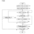
- FIG. 6 is a flowchart showing a processing procedure where the information processing apparatus 10 receives a selection input of GUI.
- the information processing apparatus 10 receives a selection input of GUI.
- the user first enters, via the touch panel 12, an instruction to start a display by selecting a content item from a menu screen displayed on the display 14 (S10), the content processing unit 24 and the display image generator 30 read necessary data from the content file storage 16 and displays an image of the content item and an image of GUI (S12).
- the information processing unit 10 waits ready until the user touches the touch panel 12 (N of S14). During this time, the processing, concerning contents, other than the processing of receiving the selection of GUI and the display updating may be performed as appropriate.
- the operating information conversion unit 22 detects the contact with the touch panel 12 (Y of S14). Then carried out is either the process of determining if the positional coordinates of GUI lies inside or outside the decision region that surrounds the contact point, as described in connection with FIG. 4 or the process of determining if the contact point lies inside or outside the decision region that surrounds the GUI, as described in connection with FIG. 5 .
- the process of determining if the positional coordinates of GUI lies inside or outside the decision region that surrounds the contact point, as described in connection with FIG. 4
- the process of determining if the contact point lies inside or outside the decision region that surrounds the GUI as described in connection with FIG. 5 .
- the GUI location control unit 26 determines the positions of the respective GUIs so that the plurality of GUIs are located on a circle, with the circle's center at the contact point, at equal spaces between the respective GUIs, and the display image generator 30 updates the display (S18). At this time, not only the positional coordinates of the contact point and the identification information on GUIs but also the original (initial) positional coordinates of the GUIs are conveyed from the operating information conversion unit 22, and the GUI location control unit 26 temporarily stores the coordinate positions in the internal memory or the like.
- the operating information conversion unit 22 will detect the contact on the touch panel 12, then identify the content associated with the selected GUI, and convey the identified content to the content processing unit 24 and thereby the information processing suitable to the identified content will be performed as appropriate (S24). If, on the other hand, no GUIs is selected in the image where the arrangement of locations of GUIs has been changed and if the user touches any of other predetermined regions on the touch panel 12 (N of S20), the operating information conversion unit 22 will convey this to the GUI location control unit 26 and thereby restore the locations of GUIs to the original positions (S22).
- the information processing unit 10 waits ready till the next contact operation (N of S14).
- the GUIs are to be restored to the original positions, the original positional coordinates stored in the internal memory and the like in Step S18 are referenced. If there is only a single GUI near the contact point in Step S16 (N of S16), the operating information conversion unit 22 will determine that this single GUI is selected, identify the operation input associated with this GUI and convey the thus identify operation input to the content processing unit 24 (S24).
- Step S24 If the user does not enter his/her instruction to terminate the displaying of content (N of S26), the processes of Steps S14 to S24 are repeated; if the user enters his/her instruction to terminate it, the processing is terminated (Y of S26). If as a result of the information processing in Step S24 it is determined that displaying the GUIs available to choose from (as options) is no longer required, the processing shown in this flowchart will be also terminated.
- the undesired situations are eliminated even if the GUIs are too closely located to each other and therefore the selection operation becomes easier.
- the undesired situations include a situation where the selection of GUI not intended by the user is recognized with the result that a careful contact operation is forced upon the user to avoid the selection of the unintended GUI.
- the achievement of a more potent effect is expected of the structure employed in the present embodiments when a contact with the touch panel is effected using a finger by which the contact is made through an area rather than a point and where a point detected as the contact point is spread over a relatively wide range. Also, the achievement thereof is expected when a smaller device in size is used where the size of GUIs is subjected to the limitation. Also, the present embodiments significantly minimize the attentions directed toward the arrangement of GUIs due to the change of screen size and therefore the burden otherwise placed on the content creators at the time of creating contents are reduced.
- a plurality of GUIs lying close to each other are placed on a circle at equal spaces therebetween wherein the center of the contact point is at the center of the circle. And a pointer graphic indicating the original position of each GUI is attached to each GUI. If the selection operation is to be interrupted, contacting a region other than the GUIs starts restoring the GUIs, which have been moved, to the original positions. The movement of GUIs onto the circle and the restoration thereof to the original positions are changes within the restrictive region surrounding the contact point. Thus, the change can be recognized without significantly changing the viewing location of the user. Furthermore, even when displaying the additional pointer graphics, the image does not become complex. As a result, the GUI to be selected can be easily and reliably selected without losing the sight of the GUI.
- the decision region(s) by which to determine whether the GUIs are located too close to each other or not is/are adaptively set according to the size of GUIs, the screen size, the content image and the like. This can suppress the occurrence of inconveniences where the icons are moved more than necessary, the intended GUI is excluded from the GUIs selectable, and so forth.
- the determination can be optimized more finely according to the importance level of each icon and the like.
- the contact operation with touch panel by the user is detected as the input information.
- the input information is not necessarily the contact operation to the touch panel so long as the user can enter the position on an image as an indication point.
- the position in a display image may be specified and inputted by operating a pointer or an icon displayed on the display image by using a pointing device such as a mouse, a trackball, a track pad, and a joystick.
- the position acquired as the input information may be expressed as one in units of "point” such as the positional coordinates of a contact point described in the above-described embodiments or may be expressed in units of region having a certain area.
- a known art may be applied to input operation, where a boundary is so drawn by moving a pointer as to surround a desired region and then a part of graphic or the like within the desired region is selected. If, in this case, there are a plurality of GUIs in the specified region, the locations of the GUIs are so varied as to widen the spaces between the GUIs. At this time, the center of a circle shaping the arrangement of GUIs may be identical to the center of gravity of the specified region, for instance. If there is only a single GUI in the specified region, the processing same as that performed when this GUI is directly selected may be performed.
- the arrangement of locations of GUIs is changed in such a direction that the spaces therebetween are enlarged.
- the same advantageous effects as those of the present embodiments can be achieved if, depending on the purpose, the arrangement is varied in such a direction that the spaces between the distributed GUIs are narrowed.
- a plurality of GUI groups are formed by gathering them together for each type and they may be arranged at equal intervals as shown in FIG. 3 in a unit of GUI group. For example, suppose that many game characters represented by GUIs are moved around or they are moved by itself, with the result that the characters are confused in a very dense state regardless of their types and therefore it becomes hard to operate. In such a case, the GUIs may be arranged with making some masses according to the types so as to allow the movement in the unit of mass.
- the types of GUIs are set in association with the image data of the GUIs and the like in advance.
- the GUI location control unit 26 splits the GUIs to be operated, based on the correspondence information, the subsequent processing will be same as that described in the above-described embodiments.
- the GUIs to be gathered together are originally distributed, they can be freely selected by specifying a region as an input information.
- this technique is especially effective with a device, such as a mobile device whose size of the display is restrictive, where it is more likely to be difficult to operate on each of GUIs that are placed closely to each other.
Landscapes
- Engineering & Computer Science (AREA)
- General Engineering & Computer Science (AREA)
- Theoretical Computer Science (AREA)
- Human Computer Interaction (AREA)
- Multimedia (AREA)
- Physics & Mathematics (AREA)
- General Physics & Mathematics (AREA)
- User Interface Of Digital Computer (AREA)
- Position Input By Displaying (AREA)
- Digital Computer Display Output (AREA)
Abstract
Description
- The present invention relates to an information processing apparatus, for example (though not exclusively) for processing information and simultaneously displaying the resulting images, as well as an information processing method employed by the information processing apparatus.
- Recent years have seen widespread use of small information devices intended for mobile use, such as mobile game devices, mobile phones, PDAs (personal digital assistants), and tablet terminals. These devices have been subject to a limited variety of input means because of their size limitations and their expected operability while they are carried around by users. As a result, the input means and functions specialized in usage for such devices have been undergoing a development on their own.
- To this end, a device capable of displaying and being input information thereon in the same region by placing a touch panel over a display has been commonly used in recent years. Provision of the touch panel like this allows the selection and movement of subjects such as icons and the enlargement/reduction, scrolling, and page turning of a display screen image on a web page or document to be conducted as if an actual thing exists before the user even though those objects, documents and the like are merely present in the two-dimensional plane. Hence, this permits intuitive responses and operations.
- The diversification and sophistication of functions provided in the information devices continue to grow regardless the size of the information devices. When the touch panel is used as the input means in such situations, more minute operation is required for displaying more sophisticated information and for a smaller-sized screen. This can be stressful to the users. Where such an operation is done by the contact of a finger in particular, an erroneous operation due to the contact area is more likely to occur as compared with the case where a stylus pen or pointing device is used. Thus, the problem of achieving an easy operation regardless of the screen size and the size of an object to be operated is yet to be addressed.
- The present invention has been made in view of these problems, and a purpose of at least embodiments thereof is to provide a technology for realizing input means having high operability even when highly sophisticated information is required to be displayed.
- Various respective aspects and features of the invention are defined in the appended claims. Combinations of features from the dependent claims may be combined with features of the independent claims as appropriate and not merely as explicitly set out in the claims.
- One embodiment of the present invention relates to an information processing apparatus. The information processing apparatus includes: an operating information acquiring unit configured to acquire information regarding a specific position, inputted by a user, in a display image and configured to detect in the display image a graphical user interface (GUI) located within a predetermined range from the specific position; a GUI location control unit configured to vary the locations of a plurality of GUIs on the display image, when the plurality of GUIs are detected by the operating information acquiring unit; and an information processing unit configured to perform information processing corresponding to a GUI, according to a user's operation on said GUI whose location has been varied.
- Another embodiment of the present invention relates to a method for processing information. The information processing method includes: acquiring information regarding a specific position, inputted by a user, in a display image and detecting in the display image a graphical user interface (GUI) located within a predetermined range from the specific position; and varying the locations of a plurality of GUIs on the display image when the plurality of GUIs are detected, and displaying the GUIs at the varied locations on a display.
- Optional combinations of the aforementioned constituting elements, and implementations of the invention in the form of methods, apparatuses, systems, recording media, computer programs, and so forth may also be practiced as additional modes of the present invention.
- Embodiments will now be described by way of examples only, with reference to the accompanying drawings which are meant to be exemplary, not limiting, and wherein like elements are numbered alike in several Figures in which:
-
FIG. 1 illustrates an example of the appearance of an information processing apparatus according to an embodiment of the present invention; -
FIG. 2 illustrates a detailed structure of an information processing apparatus according to an embodiment; -
FIG. 3 illustrates exemplary display images before and after a change of locations of GUIs; -
FIG. 4 is a diagram to explain a method whereby an operating information conversion unit determines whether the locations of a plurality of icons are to be varied or not, according to an embodiment; -
FIG. 5 is a diagram to explain another method whereby an operating information conversion unit determines whether the locations of a plurality of icons are to be varied or not, according to an embodiment; and -
FIG. 6 is a flowchart showing a processing procedure, where an information processing apparatus receives a GUI selection input, in an embodiment. - The invention will now be described by reference to the preferred embodiments. This does not intend to limit the scope of the present invention, but to exemplify the invention.
-
FIG. 1 illustrates an example of the appearance of an information processing apparatus according to an embodiment of the present invention. The information processing apparatus may be any one of a mobile phone, a portable digital assistant (PDA), a mobile game device, a tablet terminal, and the like that are each provided with a display function and the other information processing functions in an integrated fashion. Alternatively, a device having the appearance like that of theinformation processing apparatus 10 as shown inFIG. 1 may be a unit used for display and input purposes, and the remaining information processing functions may be provided in a separate casing that connects to said unit. Theinformation processing apparatus 10 may be provided with various types of mechanism and components according to the functions. Since a known art may be used for such mechanisms and components, the description thereof will be omitted as appropriate. - The
information processing apparatus 10 is structured such that the adisplay 14 is placed in from of the body of theinformation processing apparatus 10 and the top surface is covered with atouch panel 12. The components required for various information processings such as a CPU, a graphics processor, an audio processor, and a memory (all of which are not shown inFIG. 1 ) are incorporated into the back side of thedisplay 14. Thedisplay 14 may be any one of a liquid crystal display, an electro luminescent display (ELD), a plasma display and the like which are commonly used today. - The
touch panel 12 may implement any of a resistive overlay method, an optical method, an electrostatic capacitance coupling method, and the like which are in practical use. The touch panel detects a contact point by afinger 7. Theinformation processing apparatus 10 may further comprise a speaker for outputting audio, an earphone connection terminal, an infrared port or wireless LAN (Local Area Network) feature used to communicate with other devices, a battery box, and the like all of which are omitted inFIG. 1 . Thedisplay 14 displays a menu screen or a screen including an icon for the input of a user's operation, a game screen, a moving-image playback screen, a text display screen, a still-image display screen or the like which indicates the results of information processings, according to the functions of theinformation processing apparatus 10. -
FIG. 2 illustrates a detailed structure of aninformation processing apparatus 10. In addition to theaforementioned touch panel 12 and thedisplay 14, theinformation processing apparatus 10 includes acontent file storage 16 for storing programs and various data for contents, an input/output (I/O)control unit 20 for controlling the receiving of signals inputted from thetouch panel 12 and the output of image data to thedisplay 14, an operatinginformation conversion unit 22 for converting an input signal from thetouch panel 12 into information regarding an operation input, acontent processing unit 24 for processing a content according to the operation input, a GUIlocation control unit 26 for controlling the location of a GUI according to the contact point, and adisplay image generator 30 for generating a display image. - In
FIG. 2 , the structural components described as functional blocks that perform various processings may be implemented hardware-wise by elements such as a CPU (Central Processing Unit), memory and other LSIs, and software-wise by image processing programs or the like. Therefore, it will be obvious to those skilled in the art that the functional blocks may be implemented by a variety of manners including hardware only, software only or a combination of both and should not be considered as limiting. - The input/
output control unit 20 connects to thetouch panel 12 and thedisplay 14 and controls the input/output of data using a commonly-used method. The input signal received from thetouch panel 12 indicates the coordinates of a contact point at which the user touches on thetouch panel 12, a movement (travel) path of the coordinates when the contact point moves continuously, and the like. A method for detecting the contact point on thetouch panel 12 differs depending on the employed detecting system and therefore the description thereof is not given here. The input/output control unit 20 also outputs a video signal for a displayed image to thedisplay 14. - The
content file storage 16 stores various types of data required for carrying out the information processing regarding the displaying of content according to the user's operation by using the touch panel. The "content" as used herein may be computer games, movies, music, novels, photographs, maps, web pages, and so forth; the types thereof and the path through which data is stored are not limited to any specific ones so long as the subjects thereof can be expressed after electronic processing. Also, the embodiments of the invention can be applied not only to general "content" but also to the general information processing for communications, schedule management, address list, spreadsheet, and the like. In the following description, all of general "content" together with such entities will be collectively referred to as the "content". - If, for example, the content is a game, the
content file storage 16 stores the program for the game, information on a player or players, information on the achievement level (score) attained at the previous game play, and so forth. If the content is a movie or music, thecontent file storage 16 stores video data or audio data that has been compressed and coded, a program used to decode and playback the video data or audio data, and so forth. Thecontent file storage 16 may be a hard disk drive or a combination of a removable recording medium (e.g., memory card, ROM disk, optical disk or magneto-optical disk) and a readout system compatible with the removable recording medium. - The operating
information conversion unit 22 acquires from the input/output control unit 20 an input signal fed from thetouch panel 12 and identifies the operation input intended by the user based on the coordinates of a contact point contained in the input signal. If, for example, a GUI (Graphical User Interface) is displayed in a screen as an on-screen display, an operation input corresponding to the GUI which is a target of a touch will be identified based on the correspondence relation between the coordinates of the contact point and the GUI position, and then convey the thus identified operation input to thecontent processing unit 24. - If there are a plurality of GUIs within a predetermined range from the contact point, the operating
information conversion unit 22 will first inform the GUIlocation control unit 26 of the presence of the GUIs. If, for example, a selection input is to be received in such a manner that a plurality of locations in a virtual world, a map, a three-dimensional object and the like displayed on thedisplay 14 are indicated by their respective icons as options, the icons may be too closely located to each other depending on the scale of the image or the location of a viewpoint. - When a plurality of GUIs are located in close proximity to each other as described above, it is not easy to accurately instruct any of the GUIs to operate through the contact of a finger. Thus, a slight wobble in a finger's position may possibly lead to the operation of an unintended GUI and this is very stressful to the user. In the present embodiment, when the presence of a plurality of GUIs that are located near the contact point is detected, the arrangement of location of the GUIs is temporarily changed so that the space between the GUIs is widened.
- Then the user touches again the primarily intended GUI after the distance between the plurality of GUIs has been enlarged as above. As a result, the operating
information conversion unit 22 recognizes that this particular GUI is operated and effected. Then the operatinginformation conversion unit 22 conveys the corresponding operation input to thecontent processing unit 24. Then the operatinginformation conversion unit 22 also detects that the location of GUIs whose distances therebetween have returned to the original (initial) positions, and conveys the thus detected result to the GUIlocation control unit 26. - The
content processing unit 24 performs processings necessary for the progress of a game and the displaying of various content items according to the operation input, using programs and image data stored in thecontent file storage 16. At this time, the GUIs such as icons indicating the options available are displayed according to the setting in a content file in such a manner that the GUIs are superposed on a content image. A known art appropriate to the content creator's intention may be used for the GUI rendering process performed by thecontent processing unit 24. - As described above, the GUI
location control unit 26 varies the arrangement of GUIs in such a manner as to widen the space between the GUIs and restore the GUIs to the their original positions according to the notification sent from the operatinginformation conversion unit 22. When the space therebetween is to be widened, the positional information on the contact point, the identification information and the positional information on a plurality of GUIs whose positions are to be varied are received from the operatinginformation conversion unit 22. The identification information on the GUIs is associated with the images of the GUIs in the content file stored in thecontent file storage 16. - Then the GUI
location control unit 26 determines the positions of the respective GUIs, whose arrangement have been changed, based on the position of the contact point and conveys the thus determined positions thereof to thedisplay image generator 30 in association with the identification information on the GUIs. When the arrangement of the GUIs is to be restored to the original (initial) arrangement, the positional information on the original positions of the respective GUIs temporarily stored in an internal memory or the like is conveyed to thedisplay image generator 30 in association with the identification information of the GUIs. Whenever the arrangement of the GUIs is to be changed and whenever the changed arrangement thereof is to be restored to the original one, the GUIlocation control unit 26 also coveys the identification information on the respective GUIs and the positional information on the GUIs after the change, to the operatinginformation conversion unit 22. Thereby, the operatinginformation conversion unit 22 updates the positional information on the GUIs stored therein to the latest one, identifies a GUI associated with the contact point and eventually identifies the content input with accuracy. - The
display image generator 30 generates image data to be outputted, in response to a request sent from thecontent processing unit 24 or the GUIlocation control unit 26 and outputs the image data to the input/output control unit 20. The image generated by thedisplay image generator 30 is an image to be newly displayed as a result of the processing by thecontent processing unit 24 or an image for which the GUI is placed in the position specified by the GUIlocation control unit 26. - In the former case, the
display image generator 30 renders a new image by, for example, reading out necessary image data from thecontent file storage 16 according to an instruction given from thecontent processing unit 24. In the latter case, thedisplay image generator 30 reads out image data of a GUI associated with the identification information conveyed from the GUIlocation control unit 26, from thecontent file storage 16 and renders images where the GUI moves to a specified position. The image thus generated is stored in a frame buffer in the input/output control unit 20 and is displayed on thedisplay 14 when the image is outputted to thedisplay 14, with the suitable timing, from the input/output control unit 20. -
FIG. 3 illustrates an exemplary display images before and after a change of locations of GUIs. In a normal display mode, animage 40, displayed on thedisplay 14, which expresses a virtual world, for instance, is first displayed as a result of information processing performed by thecontent processing unit 24 according to a content item. In theimage 40, the locations where items are selectable are indicated by sixicons - Though, in
FIG. 3 , graphics marked with the encircled numbers "1" to "6" are theicons information processing apparatus 10.. - When, in the
image 40, the user touches acontact point 44 indicated by the filled black circle, the operatinginformation conversion unit 22 determines whether there are plurality of icons in a predetermined range from thecontact point 44 or not. Assume, for example, inFIG. 4 that the fouricons icons location control unit 26.Image 46 ofFIG. 4 illustrates the arrangement thereof after the spaces therebetween have been widened. It is appreciated here that the "predetermined range" serving as a decision criterion based on which the arrangement thereof is varied may differ for each icon. Concrete examples will be discussed later. - In the
image 46, the fouricons circle 48 is divided into N equal parts. Then, a pointer graphic, such as a pointer graphic 50a for theicon 42a, which points toward the original position of each icon in the original (initial)image 40 is attached to each icon. Besides a needle-like shape as shown inFIG. 3 , the pointer graphic may be of any arbitrary form, such as arrow, straight line and curved line, so long as the point graphic can associate the icon with its original position. Each icon is preferably placed in a position near its original position in order that the pointer graphic does not intersect or overlap with the other ones. - A transition stage from the
image 40 to theimage 46 may be expressed by actions, such as an animation, where the pointer graphic expands while each icon is moving. A touch for the contact point in theoriginal image 40 may be a "touch" in a general sense such as a contact with thetouch panel 12 for a short time, and the user may release his/her finger in theimage 46 at the time when theimage 46 after the change is displayed. It should be noted here that the black circle representing thecontact point 44 and thecircle 48 depicted inFIG. 3 are for illustration purposes only and are not necessarily displayed on the screen (or even does not have to be displayed at all in the actual setting). - However, the image may be processed such that the
contact point 44 and thecircle 48 can be viewed or visually recognized for the purpose of rendering a special effect or the like. If, for example, the icons selectable are limited to only theicons circle 48 or a band-like region with thecircle 48 as the center curved line is subjected to shading-off effect or is filled with a single color. A line, a rectangle, a polygon, a shape resembling a symbol of some sort, and the like may be used in place of thecircle 48. Also, the size of thecircle 48 may be adaptively varied such that, for example, the greater the number of icons whose locations are to be changed is, the larger the size of thecircle 48 will be. - When the user touches any one of icons located on the
circle 48 while theimage 46 after the change is being displayed, the operatinginformation conversion unit 22 recognizes that the icon has been selected and identifies the operation input corresponding to the selected icon, and thereby thecontent processing unit 24 performs the information processing as appropriate. For example, an item represented by the selected icon is zoomed up; the content of a file associated with the icon is displayed; or another program associated with the icon is started. An operation on the icon selected may be performed at once such that the contact point is moved continuously from a starting point to an ending point. Here, the starting point corresponds to the touch of thecontact point 44 in theimage 40, and the ending point correspond to the touch of a desired icon in theimage 46 after the change. - When, on the other hand, the user touches a predetermined region other than the icons located on the circle 48 (e.g., a region outside the circle 48), the icons whose locations have been changed are restored to the original positions under the control of the GUI
location control unit 26 and thereby theimage 40 is displayed again. At this time, by invalidating the contact on icons other than the icons moved onto thecircle 48, no confusion will arise between the operation of restoring the locations of icons to the original positions and the operation of selecting an icon. Alternatively, a graphic or figure may be displayed so that the original position of thecontact point 44 can be viewed and thereby the contact on this graphic may work to restore the locations of icons to the original positions thereof. In this case, any of the icons located outside thecircuit 48 may also be selected. -
FIG. 4 is a diagram to explain a method whereby an operating information conversion unit determines whether the locations of a plurality of icons are to be varied or not. InFIG. 4 , arectangle 60 represents a screen plane, and it is assumed that the sixicons FIG. 3 are arranged similarly. The operatinginformation conversion unit 22 constantly acquires the positional coordinates of each icon in a screen coordinate system determined by thecontent processing unit 24 through a process concerning the displaying of content. - As the input/
output control unit 20 conveys the positional information on thecontact point 44 on thetouch panel 12, the operatinginformation conversion unit 22 converts the positional information thereon into the positional coordinates in the screen coordinate system. Though theicons contact point 44 are expressed as circles, the information stored in the operatinginformation conversion unit 22 is the coordinates of the centers, for instance. - Then a
circular decision region 62 having a predetermined radius with the coordinates of thecontact point 44 located at the center of the circular decision region is set, and an icon or icons whose positional coordinates lie within thedecision region 62 is/are detected. That is, detected is/are an icon or icons whose distance from thecontact point 44 is less than or equal to a threshold value which is the predetermined radius. If there are a plurality of such icons, it will be determined that the arrangement of locations of such icons needs to be changed and then the presence of such icons will be conveyed to the GUIlocation control unit 26. In this case ofFIG. 4 , theicons FIG. 3 . - The radius of the
decision region 62 is determined according to the size of screen, the size of icon to be displayed, the average size of fingers, and so forth. The thus determined information may be added to the content file, so that, for example, the radius thereof can be varied according to the content. It is preferable that the size of a circle on which the icons are placed (e.g., the size of thecircle 48 as shown inFIG. 3 ) is larger than that of thedecision region 62. This gives an impression of a display change more suitable to achieve the purpose of expanding the closely located icons. -
FIG. 5 is a diagram to explain another method whereby an operating information conversion unit determines whether the locations of a plurality of icons are to be varied or not. The configuration of this figure and the arrangement of icons are similar to those shown inFIG. 4 . In this case, the operatinginformation conversion unit 22 sets, for each icon, a decision region having a predetermined radius with the coordinates of each icon located at the center of the circular decision region, based on the coordinates of each icon acquired from thecontent processing unit 24. In theFIG. 5 ,decision regions icons - Then an icon or icons that contain/contains the coordinates of the
contact point 44 lying within the decision regions is/are detected. In this case, too, detected is/are an icon or icons whose distance from thecontact point 44 is less than or equal to a threshold value which is the radius of each decision region. If there are a plurality of such icons, it will be determined that the arrangement of locations of such icons needs to be changed. In this case ofFIG. 5 , theicons decision region 72e set for theicon 42e denoted as "5" in FIG. 7 is larger than the size of the decision regions of the other icons. - If the size of the decision region is set to a larger value, an icon located a bit far from the
contact point 44 can be among those selectable in the image where the arrangement of icons has been changed. Using this property, the size of a decision region is made to vary depending on the frequency of being selected and the level of importance. Hence, the chance of being among those selectable can be increased or reduced and therefore the selection efficiency is improved. The information concerning the size of the decision region of each icon determined according to the level of importance and the like may be included in the content file. If the importance level of an icon varies according to the progress degree of a game and the like, several different patterns may be set for the size of the decision region and those patterns may be switched according to the progress degree thereof. - Such a mode of increasing or reducing the chance of being among those selectable can be achieved in the case of
FIG. 4 as well. That is, two different sizes (i.e., one large and the other small in size) of decision regions whose center is thecontact point 44 are prepared and the importance level is assigned to each icon beforehand. And then, all icons located within a small decision region, and icons, other than those icons located within the small decision region, located within a large decision region and whose importance level is greater than or equal to a threshold value are set as those selectable. Hence, even if an icon or icons are located a bit far from the contact point, such an icon or icons having a higher importance level can be set to those among selectable. Similarly, three or more different sizes of decision regions may be prepared and therefore the icons may be determined in multiple stages. - A description is now given of an operation of the
information processing apparatus 10 achieved by the above-described structure. Since the information processing and image display processing other than the processing related to the selection operation among a plurality of GUIs may be conceivable in various manners and are executed as appropriate using a general technique, a description thereof is omitted here. -
FIG. 6 is a flowchart showing a processing procedure where theinformation processing apparatus 10 receives a selection input of GUI. As the user first enters, via thetouch panel 12, an instruction to start a display by selecting a content item from a menu screen displayed on the display 14 (S10), thecontent processing unit 24 and thedisplay image generator 30 read necessary data from thecontent file storage 16 and displays an image of the content item and an image of GUI (S12). - In this condition, the
information processing unit 10 waits ready until the user touches the touch panel 12 (N of S14). During this time, the processing, concerning contents, other than the processing of receiving the selection of GUI and the display updating may be performed as appropriate. When the user touches thetouch panel 12, the operatinginformation conversion unit 22 detects the contact with the touch panel 12 (Y of S14). Then carried out is either the process of determining if the positional coordinates of GUI lies inside or outside the decision region that surrounds the contact point, as described in connection withFIG. 4 or the process of determining if the contact point lies inside or outside the decision region that surrounds the GUI, as described in connection withFIG. 5 . By carrying out either one of the processes, whether or not there are a plurality of GUIs within a predetermined range from the contact point can be determined (S16). - When a plurality of GUIs are detected near the contact point (Y of S16), the GUI
location control unit 26 determines the positions of the respective GUIs so that the plurality of GUIs are located on a circle, with the circle's center at the contact point, at equal spaces between the respective GUIs, and thedisplay image generator 30 updates the display (S18). At this time, not only the positional coordinates of the contact point and the identification information on GUIs but also the original (initial) positional coordinates of the GUIs are conveyed from the operatinginformation conversion unit 22, and the GUIlocation control unit 26 temporarily stores the coordinate positions in the internal memory or the like. - If the user touches the
touch panel 12 to select any one of GUIs in the image where the arrangement of locations of GUIs has been changed (Y of S20), the operatinginformation conversion unit 22 will detect the contact on thetouch panel 12, then identify the content associated with the selected GUI, and convey the identified content to thecontent processing unit 24 and thereby the information processing suitable to the identified content will be performed as appropriate (S24). If, on the other hand, no GUIs is selected in the image where the arrangement of locations of GUIs has been changed and if the user touches any of other predetermined regions on the touch panel 12 (N of S20), the operatinginformation conversion unit 22 will convey this to the GUIlocation control unit 26 and thereby restore the locations of GUIs to the original positions (S22). - In this state, the
information processing unit 10 waits ready till the next contact operation (N of S14). When the GUIs are to be restored to the original positions, the original positional coordinates stored in the internal memory and the like in Step S18 are referenced. If there is only a single GUI near the contact point in Step S16 (N of S16), the operatinginformation conversion unit 22 will determine that this single GUI is selected, identify the operation input associated with this GUI and convey the thus identify operation input to the content processing unit 24 (S24). - If the user does not enter his/her instruction to terminate the displaying of content (N of S26), the processes of Steps S14 to S24 are repeated; if the user enters his/her instruction to terminate it, the processing is terminated (Y of S26). If as a result of the information processing in Step S24 it is determined that displaying the GUIs available to choose from (as options) is no longer required, the processing shown in this flowchart will be also terminated.
- By employing the above-described embodiments, when a GUI is selected through a contact with the touch panel from among the GUIs displayed on the display provided in the information processing apparatus, which indicate the functions available to choose from, such as icons, the presence or state of a plurality of GUIs located near the contact point is detected. And the image where the spaces between the plurality of GUIs are enlarged is displayed. Then a selection input from any one of the GUIs is received and the processing corresponding to the received selection input is carried out. As a result, the undesired situations are eliminated even if the GUIs are too closely located to each other and therefore the selection operation becomes easier. Here, the undesired situations include a situation where the selection of GUI not intended by the user is recognized with the result that a careful contact operation is forced upon the user to avoid the selection of the unintended GUI.
- The achievement of a more potent effect is expected of the structure employed in the present embodiments when a contact with the touch panel is effected using a finger by which the contact is made through an area rather than a point and where a point detected as the contact point is spread over a relatively wide range. Also, the achievement thereof is expected when a smaller device in size is used where the size of GUIs is subjected to the limitation. Also, the present embodiments significantly minimize the attentions directed toward the arrangement of GUIs due to the change of screen size and therefore the burden otherwise placed on the content creators at the time of creating contents are reduced.
- A plurality of GUIs lying close to each other are placed on a circle at equal spaces therebetween wherein the center of the contact point is at the center of the circle. And a pointer graphic indicating the original position of each GUI is attached to each GUI. If the selection operation is to be interrupted, contacting a region other than the GUIs starts restoring the GUIs, which have been moved, to the original positions. The movement of GUIs onto the circle and the restoration thereof to the original positions are changes within the restrictive region surrounding the contact point. Thus, the change can be recognized without significantly changing the viewing location of the user. Furthermore, even when displaying the additional pointer graphics, the image does not become complex. As a result, the GUI to be selected can be easily and reliably selected without losing the sight of the GUI.
- Further, the decision region(s) by which to determine whether the GUIs are located too close to each other or not is/are adaptively set according to the size of GUIs, the screen size, the content image and the like. This can suppress the occurrence of inconveniences where the icons are moved more than necessary, the intended GUI is excluded from the GUIs selectable, and so forth. By setting the decision region for each icon, the determination can be optimized more finely according to the importance level of each icon and the like.
- The present invention has been described based upon illustrative embodiments. The above-described embodiments are intended to be illustrative only and it will be obvious to those skilled in the art that various modifications to the combination of constituting elements and processes could be developed and that such modifications are also within the scope of the present invention.
- For example, in the present embodiments, the contact operation with touch panel by the user is detected as the input information. The input information is not necessarily the contact operation to the touch panel so long as the user can enter the position on an image as an indication point. For example, the position in a display image may be specified and inputted by operating a pointer or an icon displayed on the display image by using a pointing device such as a mouse, a trackball, a track pad, and a joystick.
- Regardless of whether the touch panel is to be employed or not, the position acquired as the input information may be expressed as one in units of "point" such as the positional coordinates of a contact point described in the above-described embodiments or may be expressed in units of region having a certain area. For example, a known art may be applied to input operation, where a boundary is so drawn by moving a pointer as to surround a desired region and then a part of graphic or the like within the desired region is selected. If, in this case, there are a plurality of GUIs in the specified region, the locations of the GUIs are so varied as to widen the spaces between the GUIs. At this time, the center of a circle shaping the arrangement of GUIs may be identical to the center of gravity of the specified region, for instance. If there is only a single GUI in the specified region, the processing same as that performed when this GUI is directly selected may be performed.
- In the present embodiments, the arrangement of locations of GUIs is changed in such a direction that the spaces therebetween are enlarged. However, the same advantageous effects as those of the present embodiments can be achieved if, depending on the purpose, the arrangement is varied in such a direction that the spaces between the distributed GUIs are narrowed. Now apply this technique to the following case. That is, if there are a plurality of kinds of GUIs, a plurality of GUI groups are formed by gathering them together for each type and they may be arranged at equal intervals as shown in
FIG. 3 in a unit of GUI group. For example, suppose that many game characters represented by GUIs are moved around or they are moved by itself, with the result that the characters are confused in a very dense state regardless of their types and therefore it becomes hard to operate. In such a case, the GUIs may be arranged with making some masses according to the types so as to allow the movement in the unit of mass. - The types of GUIs are set in association with the image data of the GUIs and the like in advance. Once the GUI
location control unit 26 splits the GUIs to be operated, based on the correspondence information, the subsequent processing will be same as that described in the above-described embodiments. In such a case, even if the GUIs to be gathered together are originally distributed, they can be freely selected by specifying a region as an input information. When the operation is enabled and carried out for each of the types that have been gathered together as described above, this technique is especially effective with a device, such as a mobile device whose size of the display is restrictive, where it is more likely to be difficult to operate on each of GUIs that are placed closely to each other. - In so far as the embodiments of the invention described above are implemented, at least in part, using software-controlled data processing apparatus, it will be appreciated that a computer program providing such software control and a transmission, storage or other medium by which such a computer program is provided are envisaged as aspects of the present invention.
Claims (9)
- An information processing apparatus (10) comprising:an operating information acquiring unit (22) configured to acquire information regarding a specific position, inputted by a user, in a display image and configured to detect in the display image a graphical user interface (GUI) located within a predetermined range from the specific position;a GUI location control unit (26) configured to vary the locations of a plurality of GUIs on the display image, when the plurality of GUIs are detected by the operating information acquiring unit (22); andan information processing unit (24) configured to perform information processing corresponding to a GUI, according to a user's operation on said GUI whose location has been varied.
- The information processing apparatus (10) according to claim 1, wherein the operating information acquiring unit (22) detects a GUI whose distance from the specific position is less than a threshold value, and
wherein the GUI location control unit (26) widens a space between the GUIs in a manner such that the plurality of GUIs detected by the operating information acquiring unit (22) are equally spaced on a circle, with the circle's center being at the specific position. - The information processing apparatus (10) according to claim 1 or 2, wherein the operating information acquiring unit (22) detects the GUI located within the predetermined range from the specific position in a manner such that the distance between each GUI and the specific position is compared with a threshold value set for each of a plurality of GUIs.
- The information processing apparatus (10) according to claim 1, wherein the operating information acquiring unit (22) detects a GUI located in a region specified as the specific position, and
wherein the GUI location control unit (26) splits the plurality of detected GUIs according to types of GUIs and puts the same type of GUIs in one place, whereby an operation of GUI in a unit of type of GUI is accepted. - The information processing apparatus (10) according to any one of claims 1 to 4, wherein, when a user's input indicates a position, within a predetermined region in an image after varying the locations of the GUIs, which does not include the GUIs of which locations have been varied, the GUI location control unit (26) respectively restores the location of each GUI to an initial position.
- The information processing apparatus (10) according to any one of claims 1 to 5, wherein the GUI location control unit (26) attaches a graphic to each GUI, the graphic indicating an initial position of the each GUI whose location has been varied.
- A method for processing information, the method comprising:acquiring information regarding a specific position, inputted by a user, in a display image and detecting in the display image a graphical user interface (GUI) located within a predetermined range from the specific position; andvarying the locations of a plurality of GUIs on the display image when the plurality of GUIs are detected, and displaying the GUIs at the varied locations on a display.
- A computer program embedded in a non-transitory computer-readable medium, the program comprising:an operating information acquiring module operative to acquire information regarding a specific position, inputted by a user, in a display image and operative to detect in the display image a graphical user interface (GUI) located within a predetermined range from the specific position; anda GUI location control module operative to vary the locations of a plurality of GUIs on the display image when the plurality of GUIs are detected by the operating information acquiring module, and operative to display the GUIs at the varied locations on a display.
- A non-transitory computer-readable medium encoded with a computer program executable by a computer, the computer program comprising:an operating information acquiring module operative to acquire information regarding a specific position, inputted by a user, in a display image and detecting in a display image a graphical user interface (GUI) located within a predetermined range from the specific position; anda GUI location control module operative to vary the locations of a plurality of GUIs on the display image when the plurality of GUIs are detected by the operating information acquiring module, and operative to display the GUIs at the varied locations on a display.
Applications Claiming Priority (1)
| Application Number | Priority Date | Filing Date | Title |
|---|---|---|---|
| JP2011255504A JP5647968B2 (en) | 2011-11-22 | 2011-11-22 | Information processing apparatus and information processing method |
Publications (3)
| Publication Number | Publication Date |
|---|---|
| EP2597559A2 true EP2597559A2 (en) | 2013-05-29 |
| EP2597559A3 EP2597559A3 (en) | 2015-12-02 |
| EP2597559B1 EP2597559B1 (en) | 2020-09-30 |
Family
ID=47177800
Family Applications (1)
| Application Number | Title | Priority Date | Filing Date |
|---|---|---|---|
| EP12191883.3A Active EP2597559B1 (en) | 2011-11-22 | 2012-11-08 | Information Processing Apparatus and Information Processing Method to Realize Input Means Having High Operability |
Country Status (4)
| Country | Link |
|---|---|
| US (2) | US12008229B2 (en) |
| EP (1) | EP2597559B1 (en) |
| JP (1) | JP5647968B2 (en) |
| CN (1) | CN103197878B (en) |
Families Citing this family (14)
| Publication number | Priority date | Publication date | Assignee | Title |
|---|---|---|---|---|
| JP5647968B2 (en) * | 2011-11-22 | 2015-01-07 | 株式会社ソニー・コンピュータエンタテインメント | Information processing apparatus and information processing method |
| JP6411067B2 (en) * | 2014-05-13 | 2018-10-24 | シャープ株式会社 | Information processing apparatus and input method |
| JP2016148965A (en) * | 2015-02-12 | 2016-08-18 | 三菱電機株式会社 | Display control apparatus and display control method |
| JP6002800B1 (en) * | 2015-03-19 | 2016-10-05 | パナソニック インテレクチュアル プロパティ コーポレーション オブ アメリカPanasonic Intellectual Property Corporation of America | Information device control method, program, and information device |
| WO2016147233A1 (en) * | 2015-03-19 | 2016-09-22 | パナソニック インテレクチュアル プロパティ コーポレーション オブ アメリカ | Information device control method, program, and information device |
| JP6002799B1 (en) * | 2015-03-19 | 2016-10-05 | パナソニック インテレクチュアル プロパティ コーポレーション オブ アメリカPanasonic Intellectual Property Corporation of America | Information device control method, program, and information device |
| WO2016147234A1 (en) * | 2015-03-19 | 2016-09-22 | パナソニック インテレクチュアル プロパティ コーポレーション オブ アメリカ | Information device control method, program, and information device |
| JP6435964B2 (en) * | 2015-03-31 | 2018-12-12 | 富士通株式会社 | Display device, program, and display method |
| JP2016192111A (en) * | 2015-03-31 | 2016-11-10 | パイオニア株式会社 | Selection device, selection method, and program for selection device |
| JP6921283B2 (en) * | 2016-03-24 | 2021-08-18 | 株式会社ゼンリンデータコム | Map display device, map display method and map display program |
| WO2018080542A1 (en) * | 2016-10-31 | 2018-05-03 | Hewlett-Packard Development Company, L.P. | Developing a non-rectangular user interface |
| WO2018083765A1 (en) * | 2016-11-02 | 2018-05-11 | マクセル株式会社 | Input operation method, input operation device, display controller, and information content receiving system |
| CN107422938A (en) * | 2017-06-21 | 2017-12-01 | 网易(杭州)网络有限公司 | Information processing method, device, electronic equipment and storage medium |
| JP2020113344A (en) * | 2020-04-27 | 2020-07-27 | パイオニア株式会社 | Selection device, selection method, and selection device program |
Family Cites Families (41)
| Publication number | Priority date | Publication date | Assignee | Title |
|---|---|---|---|---|
| US5963671A (en) * | 1991-11-27 | 1999-10-05 | International Business Machines Corporation | Enhancement of soft keyboard operations using trigram prediction |
| US6046722A (en) * | 1991-12-05 | 2000-04-04 | International Business Machines Corporation | Method and system for enabling blind or visually impaired computer users to graphically select displayed elements |
| US5757358A (en) * | 1992-03-31 | 1998-05-26 | The United States Of America As Represented By The Secretary Of The Navy | Method and apparatus for enhancing computer-user selection of computer-displayed objects through dynamic selection area and constant visual feedback |
| KR100260760B1 (en) * | 1996-07-31 | 2000-07-01 | 모리 하루오 | Information display device with a touch panel |
| US6259436B1 (en) * | 1998-12-22 | 2001-07-10 | Ericsson Inc. | Apparatus and method for determining selection of touchable items on a computer touchscreen by an imprecise touch |
| JP2001101304A (en) * | 1999-10-04 | 2001-04-13 | Canon Inc | Information processing method, apparatus and storage medium |
| US7730401B2 (en) * | 2001-05-16 | 2010-06-01 | Synaptics Incorporated | Touch screen with user interface enhancement |
| US6844887B2 (en) * | 2001-07-05 | 2005-01-18 | International Business Machine Corporation | Alternate reduced size on-screen pointers for accessing selectable icons in high icon density regions of user interactive display interfaces |
| US6886138B2 (en) * | 2001-07-05 | 2005-04-26 | International Business Machines Corporation | Directing users′ attention to specific icons being approached by an on-screen pointer on user interactive display interfaces |
| US6816176B2 (en) * | 2001-07-05 | 2004-11-09 | International Business Machines Corporation | Temporarily moving adjacent or overlapping icons away from specific icons being approached by an on-screen pointer on user interactive display interfaces |
| US6856901B2 (en) * | 2003-06-02 | 2005-02-15 | Alpine Electronics, Inc. | Display method and apparatus for navigation system |
| JP4159491B2 (en) * | 2004-02-23 | 2008-10-01 | 任天堂株式会社 | GAME PROGRAM AND GAME DEVICE |
| US7506274B2 (en) * | 2005-05-18 | 2009-03-17 | Microsoft Corporation | System and method for interactively displaying multi-dimensional data |
| JP4163718B2 (en) * | 2006-02-28 | 2008-10-08 | 株式会社コナミデジタルエンタテインメント | Object display device, object arrangement method, and program |
| US20080166558A1 (en) | 2006-12-22 | 2008-07-10 | 3M Innovative Properties Company | Compositions of particles |
| JP4899991B2 (en) * | 2007-03-30 | 2012-03-21 | 富士ゼロックス株式会社 | Display device and program |
| US8381122B2 (en) * | 2007-06-08 | 2013-02-19 | Apple Inc. | Multi-dimensional application environment |
| KR20090036877A (en) * | 2007-10-10 | 2009-04-15 | 삼성전자주식회사 | Method and system for managing objects based on criteria in multi-projection window environment |
| JP2010021766A (en) * | 2008-07-10 | 2010-01-28 | Ricoh Co Ltd | Image display apparatus, image display method, program, and storage medium |
| JP5060430B2 (en) * | 2008-08-28 | 2012-10-31 | 株式会社東芝 | Display control apparatus and method |
| KR101570116B1 (en) * | 2008-09-09 | 2015-11-19 | 삼성전자주식회사 | How to search and execute contents using touch screen and devices using it |
| US20100077361A1 (en) * | 2008-09-24 | 2010-03-25 | Andrew Watkins | Method of displaying multiple points of interest on a personal navigation device |
| US8516397B2 (en) * | 2008-10-27 | 2013-08-20 | Verizon Patent And Licensing Inc. | Proximity interface apparatuses, systems, and methods |
| US8300023B2 (en) * | 2009-04-10 | 2012-10-30 | Qualcomm Incorporated | Virtual keypad generator with learning capabilities |
| US8549432B2 (en) * | 2009-05-29 | 2013-10-01 | Apple Inc. | Radial menus |
| US20100315266A1 (en) * | 2009-06-15 | 2010-12-16 | Microsoft Corporation | Predictive interfaces with usability constraints |
| US20110041056A1 (en) * | 2009-08-14 | 2011-02-17 | Research In Motion Limited | Electronic device with touch-sensitive display and method of facilitating input at the electronic device |
| US8667424B2 (en) * | 2009-08-26 | 2014-03-04 | Mitac International Corp. | Method of spreading out and displaying closely located points of interest on a personal navigation device |
| US8812972B2 (en) * | 2009-09-30 | 2014-08-19 | At&T Intellectual Property I, L.P. | Dynamic generation of soft keyboards for mobile devices |
| US8558849B2 (en) * | 2009-12-14 | 2013-10-15 | Samsung Electronics Co., Ltd. | Method and apparatus for processing a user interface in an image processor |
| JP2010086559A (en) * | 2010-01-18 | 2010-04-15 | Toshiba Corp | Display processing device, program, and display processing method |
| JP5440322B2 (en) | 2010-03-29 | 2014-03-12 | 株式会社豊田自動織機 | Manufacturing method of electronic component device |
| JP2011210083A (en) * | 2010-03-30 | 2011-10-20 | Panasonic Corp | Display device |
| US20110252349A1 (en) * | 2010-04-07 | 2011-10-13 | Imran Chaudhri | Device, Method, and Graphical User Interface for Managing Folders |
| JP5614173B2 (en) * | 2010-08-25 | 2014-10-29 | ソニー株式会社 | Information processing apparatus, information processing method, and program |
| CN102419679B (en) * | 2010-09-27 | 2014-10-01 | 联想(北京)有限公司 | Display processing method and portable mobile terminal |
| JP5260694B2 (en) * | 2011-02-28 | 2013-08-14 | 株式会社コナミデジタルエンタテインメント | Information processing apparatus, information processing apparatus control method, and program |
| JP5647968B2 (en) * | 2011-11-22 | 2015-01-07 | 株式会社ソニー・コンピュータエンタテインメント | Information processing apparatus and information processing method |
| US8860763B2 (en) * | 2012-01-31 | 2014-10-14 | Xerox Corporation | Reversible user interface component |
| US9921732B2 (en) * | 2013-07-31 | 2018-03-20 | Splunk Inc. | Radial graphs for visualizing data in real-time |
| JP5888306B2 (en) * | 2013-10-11 | 2016-03-22 | セイコーエプソン株式会社 | User information input device, input screen display method, and input screen display program |
-
2011
- 2011-11-22 JP JP2011255504A patent/JP5647968B2/en active Active
-
2012
- 2012-09-12 US US13/611,242 patent/US12008229B2/en active Active
- 2012-11-08 EP EP12191883.3A patent/EP2597559B1/en active Active
- 2012-11-20 CN CN201210471993.1A patent/CN103197878B/en active Active
-
2024
- 2024-05-02 US US18/652,853 patent/US20240281136A1/en not_active Abandoned
Non-Patent Citations (1)
| Title |
|---|
| None |
Also Published As
| Publication number | Publication date |
|---|---|
| EP2597559A3 (en) | 2015-12-02 |
| JP5647968B2 (en) | 2015-01-07 |
| US12008229B2 (en) | 2024-06-11 |
| US20240281136A1 (en) | 2024-08-22 |
| EP2597559B1 (en) | 2020-09-30 |
| US20130132873A1 (en) | 2013-05-23 |
| CN103197878B (en) | 2017-07-21 |
| CN103197878A (en) | 2013-07-10 |
| JP2013109668A (en) | 2013-06-06 |
Similar Documents
| Publication | Publication Date | Title |
|---|---|---|
| US20240281136A1 (en) | Varying icons to improve operability | |
| JP5204286B2 (en) | Electronic device and input method | |
| EP2214088A2 (en) | Information processing | |
| US8024004B2 (en) | Device having display buttons and display method and medium for the device | |
| US9841890B2 (en) | Information processing device and information processing method for improving operability in selecting graphical user interface by generating multiple virtual points of contact | |
| CN108268187A (en) | The display methods and device of intelligent terminal | |
| EP2169529A2 (en) | Information processing | |
| US20170139589A1 (en) | Display device, display controlling method, and computer program | |
| WO2019024700A1 (en) | Emoji display method and device, and computer readable storage medium | |
| CN107870725A (en) | Screen recording method, device and terminal | |
| US20130132889A1 (en) | Information processing apparatus and information processing method to achieve efficient screen scrolling | |
| US20130342455A1 (en) | Display apparatus, remote controlling apparatus and control method thereof | |
| WO2015126682A1 (en) | Hover interactions across interconnected devices | |
| WO2012066591A1 (en) | Electronic apparatus, menu display method, content image display method, function execution method | |
| JP6514376B1 (en) | Game program, method, and information processing apparatus | |
| US9274632B2 (en) | Portable electronic device, touch operation processing method, and program | |
| US8787931B2 (en) | Terminal with virtual space interface and method of controlling virtual space interface | |
| CN111596815A (en) | Application icon display method and electronic device | |
| CN111596822A (en) | Icon display control method and device and electronic equipment | |
| CN111443819A (en) | Control method and electronic device | |
| JP7210153B2 (en) | ELECTRONIC DEVICE, ELECTRONIC DEVICE CONTROL METHOD, PROGRAM, AND STORAGE MEDIUM | |
| KR101528485B1 (en) | System and method for virtual reality service based in smart device | |
| JPWO2014024281A1 (en) | Electronic device, display control method and program | |
| WO2017165254A1 (en) | Selecting first digital input behavior based on presence of a second, concurrent, input | |
| KR20200049737A (en) | List scroll bar control method and mobile apparatus |
Legal Events
| Date | Code | Title | Description |
|---|---|---|---|
| PUAI | Public reference made under article 153(3) epc to a published international application that has entered the european phase |
Free format text: ORIGINAL CODE: 0009012 |
|
| 17P | Request for examination filed |
Effective date: 20121123 |
|
| AK | Designated contracting states |
Kind code of ref document: A2 Designated state(s): AL AT BE BG CH CY CZ DE DK EE ES FI FR GB GR HR HU IE IS IT LI LT LU LV MC MK MT NL NO PL PT RO RS SE SI SK SM TR |
|
| AX | Request for extension of the european patent |
Extension state: BA ME |
|
| PUAL | Search report despatched |
Free format text: ORIGINAL CODE: 0009013 |
|
| AK | Designated contracting states |
Kind code of ref document: A3 Designated state(s): AL AT BE BG CH CY CZ DE DK EE ES FI FR GB GR HR HU IE IS IT LI LT LU LV MC MK MT NL NO PL PT RO RS SE SI SK SM TR |
|
| AX | Request for extension of the european patent |
Extension state: BA ME |
|
| RIC1 | Information provided on ipc code assigned before grant |
Ipc: G06F 3/0484 20130101ALI20151023BHEP Ipc: G06F 3/0488 20130101AFI20151023BHEP |
|
| RAP1 | Party data changed (applicant data changed or rights of an application transferred) |
Owner name: SONY INTERACTIVE ENTERTAINMENT INC. |
|
| STAA | Information on the status of an ep patent application or granted ep patent |
Free format text: STATUS: EXAMINATION IS IN PROGRESS |
|
| 17Q | First examination report despatched |
Effective date: 20170228 |
|
| RAP1 | Party data changed (applicant data changed or rights of an application transferred) |
Owner name: SONY INTERACTIVE ENTERTAINMENT INC. |
|
| GRAP | Despatch of communication of intention to grant a patent |
Free format text: ORIGINAL CODE: EPIDOSNIGR1 |
|
| STAA | Information on the status of an ep patent application or granted ep patent |
Free format text: STATUS: GRANT OF PATENT IS INTENDED |
|
| INTG | Intention to grant announced |
Effective date: 20200506 |
|
| GRAS | Grant fee paid |
Free format text: ORIGINAL CODE: EPIDOSNIGR3 |
|
| GRAA | (expected) grant |
Free format text: ORIGINAL CODE: 0009210 |
|
| STAA | Information on the status of an ep patent application or granted ep patent |
Free format text: STATUS: THE PATENT HAS BEEN GRANTED |
|
| AK | Designated contracting states |
Kind code of ref document: B1 Designated state(s): AL AT BE BG CH CY CZ DE DK EE ES FI FR GB GR HR HU IE IS IT LI LT LU LV MC MK MT NL NO PL PT RO RS SE SI SK SM TR |
|
| REG | Reference to a national code |
Ref country code: CH Ref legal event code: EP Ref country code: GB Ref legal event code: FG4D |
|
| REG | Reference to a national code |
Ref country code: DE Ref legal event code: R096 Ref document number: 602012072544 Country of ref document: DE Ref country code: AT Ref legal event code: REF Ref document number: 1319493 Country of ref document: AT Kind code of ref document: T Effective date: 20201015 |
|
| REG | Reference to a national code |
Ref country code: IE Ref legal event code: FG4D |
|
| PG25 | Lapsed in a contracting state [announced via postgrant information from national office to epo] |
Ref country code: HR Free format text: LAPSE BECAUSE OF FAILURE TO SUBMIT A TRANSLATION OF THE DESCRIPTION OR TO PAY THE FEE WITHIN THE PRESCRIBED TIME-LIMIT Effective date: 20200930 Ref country code: GR Free format text: LAPSE BECAUSE OF FAILURE TO SUBMIT A TRANSLATION OF THE DESCRIPTION OR TO PAY THE FEE WITHIN THE PRESCRIBED TIME-LIMIT Effective date: 20201231 Ref country code: FI Free format text: LAPSE BECAUSE OF FAILURE TO SUBMIT A TRANSLATION OF THE DESCRIPTION OR TO PAY THE FEE WITHIN THE PRESCRIBED TIME-LIMIT Effective date: 20200930 Ref country code: SE Free format text: LAPSE BECAUSE OF FAILURE TO SUBMIT A TRANSLATION OF THE DESCRIPTION OR TO PAY THE FEE WITHIN THE PRESCRIBED TIME-LIMIT Effective date: 20200930 Ref country code: NO Free format text: LAPSE BECAUSE OF FAILURE TO SUBMIT A TRANSLATION OF THE DESCRIPTION OR TO PAY THE FEE WITHIN THE PRESCRIBED TIME-LIMIT Effective date: 20201230 Ref country code: BG Free format text: LAPSE BECAUSE OF FAILURE TO SUBMIT A TRANSLATION OF THE DESCRIPTION OR TO PAY THE FEE WITHIN THE PRESCRIBED TIME-LIMIT Effective date: 20201230 |
|
| REG | Reference to a national code |
Ref country code: AT Ref legal event code: MK05 Ref document number: 1319493 Country of ref document: AT Kind code of ref document: T Effective date: 20200930 |
|
| PG25 | Lapsed in a contracting state [announced via postgrant information from national office to epo] |
Ref country code: RS Free format text: LAPSE BECAUSE OF FAILURE TO SUBMIT A TRANSLATION OF THE DESCRIPTION OR TO PAY THE FEE WITHIN THE PRESCRIBED TIME-LIMIT Effective date: 20200930 Ref country code: LV Free format text: LAPSE BECAUSE OF FAILURE TO SUBMIT A TRANSLATION OF THE DESCRIPTION OR TO PAY THE FEE WITHIN THE PRESCRIBED TIME-LIMIT Effective date: 20200930 |
|
| REG | Reference to a national code |
Ref country code: NL Ref legal event code: MP Effective date: 20200930 |
|
| REG | Reference to a national code |
Ref country code: LT Ref legal event code: MG4D |
|
| PG25 | Lapsed in a contracting state [announced via postgrant information from national office to epo] |
Ref country code: CZ Free format text: LAPSE BECAUSE OF FAILURE TO SUBMIT A TRANSLATION OF THE DESCRIPTION OR TO PAY THE FEE WITHIN THE PRESCRIBED TIME-LIMIT Effective date: 20200930 Ref country code: EE Free format text: LAPSE BECAUSE OF FAILURE TO SUBMIT A TRANSLATION OF THE DESCRIPTION OR TO PAY THE FEE WITHIN THE PRESCRIBED TIME-LIMIT Effective date: 20200930 Ref country code: RO Free format text: LAPSE BECAUSE OF FAILURE TO SUBMIT A TRANSLATION OF THE DESCRIPTION OR TO PAY THE FEE WITHIN THE PRESCRIBED TIME-LIMIT Effective date: 20200930 Ref country code: SM Free format text: LAPSE BECAUSE OF FAILURE TO SUBMIT A TRANSLATION OF THE DESCRIPTION OR TO PAY THE FEE WITHIN THE PRESCRIBED TIME-LIMIT Effective date: 20200930 Ref country code: NL Free format text: LAPSE BECAUSE OF FAILURE TO SUBMIT A TRANSLATION OF THE DESCRIPTION OR TO PAY THE FEE WITHIN THE PRESCRIBED TIME-LIMIT Effective date: 20200930 Ref country code: PT Free format text: LAPSE BECAUSE OF FAILURE TO SUBMIT A TRANSLATION OF THE DESCRIPTION OR TO PAY THE FEE WITHIN THE PRESCRIBED TIME-LIMIT Effective date: 20210201 Ref country code: LT Free format text: LAPSE BECAUSE OF FAILURE TO SUBMIT A TRANSLATION OF THE DESCRIPTION OR TO PAY THE FEE WITHIN THE PRESCRIBED TIME-LIMIT Effective date: 20200930 |
|
| PG25 | Lapsed in a contracting state [announced via postgrant information from national office to epo] |
Ref country code: AL Free format text: LAPSE BECAUSE OF FAILURE TO SUBMIT A TRANSLATION OF THE DESCRIPTION OR TO PAY THE FEE WITHIN THE PRESCRIBED TIME-LIMIT Effective date: 20200930 Ref country code: AT Free format text: LAPSE BECAUSE OF FAILURE TO SUBMIT A TRANSLATION OF THE DESCRIPTION OR TO PAY THE FEE WITHIN THE PRESCRIBED TIME-LIMIT Effective date: 20200930 Ref country code: ES Free format text: LAPSE BECAUSE OF FAILURE TO SUBMIT A TRANSLATION OF THE DESCRIPTION OR TO PAY THE FEE WITHIN THE PRESCRIBED TIME-LIMIT Effective date: 20200930 Ref country code: IS Free format text: LAPSE BECAUSE OF FAILURE TO SUBMIT A TRANSLATION OF THE DESCRIPTION OR TO PAY THE FEE WITHIN THE PRESCRIBED TIME-LIMIT Effective date: 20210130 Ref country code: PL Free format text: LAPSE BECAUSE OF FAILURE TO SUBMIT A TRANSLATION OF THE DESCRIPTION OR TO PAY THE FEE WITHIN THE PRESCRIBED TIME-LIMIT Effective date: 20200930 |
|
| PG25 | Lapsed in a contracting state [announced via postgrant information from national office to epo] |
Ref country code: SK Free format text: LAPSE BECAUSE OF FAILURE TO SUBMIT A TRANSLATION OF THE DESCRIPTION OR TO PAY THE FEE WITHIN THE PRESCRIBED TIME-LIMIT Effective date: 20200930 Ref country code: MC Free format text: LAPSE BECAUSE OF FAILURE TO SUBMIT A TRANSLATION OF THE DESCRIPTION OR TO PAY THE FEE WITHIN THE PRESCRIBED TIME-LIMIT Effective date: 20200930 |
|
| REG | Reference to a national code |
Ref country code: CH Ref legal event code: PL |
|
| REG | Reference to a national code |
Ref country code: DE Ref legal event code: R097 Ref document number: 602012072544 Country of ref document: DE |
|
| PG25 | Lapsed in a contracting state [announced via postgrant information from national office to epo] |
Ref country code: LU Free format text: LAPSE BECAUSE OF NON-PAYMENT OF DUE FEES Effective date: 20201108 |
|
| PLBE | No opposition filed within time limit |
Free format text: ORIGINAL CODE: 0009261 |
|
| STAA | Information on the status of an ep patent application or granted ep patent |
Free format text: STATUS: NO OPPOSITION FILED WITHIN TIME LIMIT |
|
| REG | Reference to a national code |
Ref country code: BE Ref legal event code: MM Effective date: 20201130 |
|
| PG25 | Lapsed in a contracting state [announced via postgrant information from national office to epo] |
Ref country code: LI Free format text: LAPSE BECAUSE OF NON-PAYMENT OF DUE FEES Effective date: 20201130 Ref country code: DK Free format text: LAPSE BECAUSE OF FAILURE TO SUBMIT A TRANSLATION OF THE DESCRIPTION OR TO PAY THE FEE WITHIN THE PRESCRIBED TIME-LIMIT Effective date: 20200930 Ref country code: CH Free format text: LAPSE BECAUSE OF NON-PAYMENT OF DUE FEES Effective date: 20201130 |
|
| 26N | No opposition filed |
Effective date: 20210701 |
|
| PG25 | Lapsed in a contracting state [announced via postgrant information from national office to epo] |
Ref country code: IT Free format text: LAPSE BECAUSE OF FAILURE TO SUBMIT A TRANSLATION OF THE DESCRIPTION OR TO PAY THE FEE WITHIN THE PRESCRIBED TIME-LIMIT Effective date: 20200930 Ref country code: IE Free format text: LAPSE BECAUSE OF NON-PAYMENT OF DUE FEES Effective date: 20201108 |
|
| PG25 | Lapsed in a contracting state [announced via postgrant information from national office to epo] |
Ref country code: SI Free format text: LAPSE BECAUSE OF FAILURE TO SUBMIT A TRANSLATION OF THE DESCRIPTION OR TO PAY THE FEE WITHIN THE PRESCRIBED TIME-LIMIT Effective date: 20200930 |
|
| PG25 | Lapsed in a contracting state [announced via postgrant information from national office to epo] |
Ref country code: IS Free format text: LAPSE BECAUSE OF FAILURE TO SUBMIT A TRANSLATION OF THE DESCRIPTION OR TO PAY THE FEE WITHIN THE PRESCRIBED TIME-LIMIT Effective date: 20210130 Ref country code: TR Free format text: LAPSE BECAUSE OF FAILURE TO SUBMIT A TRANSLATION OF THE DESCRIPTION OR TO PAY THE FEE WITHIN THE PRESCRIBED TIME-LIMIT Effective date: 20200930 Ref country code: MT Free format text: LAPSE BECAUSE OF FAILURE TO SUBMIT A TRANSLATION OF THE DESCRIPTION OR TO PAY THE FEE WITHIN THE PRESCRIBED TIME-LIMIT Effective date: 20200930 Ref country code: CY Free format text: LAPSE BECAUSE OF FAILURE TO SUBMIT A TRANSLATION OF THE DESCRIPTION OR TO PAY THE FEE WITHIN THE PRESCRIBED TIME-LIMIT Effective date: 20200930 |
|
| PG25 | Lapsed in a contracting state [announced via postgrant information from national office to epo] |
Ref country code: MK Free format text: LAPSE BECAUSE OF FAILURE TO SUBMIT A TRANSLATION OF THE DESCRIPTION OR TO PAY THE FEE WITHIN THE PRESCRIBED TIME-LIMIT Effective date: 20200930 |
|
| PG25 | Lapsed in a contracting state [announced via postgrant information from national office to epo] |
Ref country code: BE Free format text: LAPSE BECAUSE OF NON-PAYMENT OF DUE FEES Effective date: 20201130 |
|
| P01 | Opt-out of the competence of the unified patent court (upc) registered |
Effective date: 20230519 |
|
| PGFP | Annual fee paid to national office [announced via postgrant information from national office to epo] |
Ref country code: DE Payment date: 20251022 Year of fee payment: 14 |
|
| PGFP | Annual fee paid to national office [announced via postgrant information from national office to epo] |
Ref country code: GB Payment date: 20251023 Year of fee payment: 14 |
|
| PGFP | Annual fee paid to national office [announced via postgrant information from national office to epo] |
Ref country code: FR Payment date: 20251022 Year of fee payment: 14 |