EP2597212B1 - Emergency stop system for a hybrid excavator - Google Patents
Emergency stop system for a hybrid excavator Download PDFInfo
- Publication number
- EP2597212B1 EP2597212B1 EP10855046.8A EP10855046A EP2597212B1 EP 2597212 B1 EP2597212 B1 EP 2597212B1 EP 10855046 A EP10855046 A EP 10855046A EP 2597212 B1 EP2597212 B1 EP 2597212B1
- Authority
- EP
- European Patent Office
- Prior art keywords
- emergency
- controller
- power supply
- hybrid
- input power
- Prior art date
- Legal status (The legal status is an assumption and is not a legal conclusion. Google has not performed a legal analysis and makes no representation as to the accuracy of the status listed.)
- Not-in-force
Links
- 230000005856 abnormality Effects 0.000 claims description 27
- 238000004146 energy storage Methods 0.000 claims description 13
- 238000010586 diagram Methods 0.000 description 4
- 230000007257 malfunction Effects 0.000 description 1
Images

Classifications
-
- H—ELECTRICITY
- H01—ELECTRIC ELEMENTS
- H01H—ELECTRIC SWITCHES; RELAYS; SELECTORS; EMERGENCY PROTECTIVE DEVICES
- H01H35/00—Switches operated by change of a physical condition
- H01H35/006—Switches operated by mechanical overload condition, e.g. transmitted force or torque becoming too high
-
- B—PERFORMING OPERATIONS; TRANSPORTING
- B60—VEHICLES IN GENERAL
- B60W—CONJOINT CONTROL OF VEHICLE SUB-UNITS OF DIFFERENT TYPE OR DIFFERENT FUNCTION; CONTROL SYSTEMS SPECIALLY ADAPTED FOR HYBRID VEHICLES; ROAD VEHICLE DRIVE CONTROL SYSTEMS FOR PURPOSES NOT RELATED TO THE CONTROL OF A PARTICULAR SUB-UNIT
- B60W10/00—Conjoint control of vehicle sub-units of different type or different function
- B60W10/04—Conjoint control of vehicle sub-units of different type or different function including control of propulsion units
- B60W10/08—Conjoint control of vehicle sub-units of different type or different function including control of propulsion units including control of electric propulsion units, e.g. motors or generators
-
- B—PERFORMING OPERATIONS; TRANSPORTING
- B60—VEHICLES IN GENERAL
- B60W—CONJOINT CONTROL OF VEHICLE SUB-UNITS OF DIFFERENT TYPE OR DIFFERENT FUNCTION; CONTROL SYSTEMS SPECIALLY ADAPTED FOR HYBRID VEHICLES; ROAD VEHICLE DRIVE CONTROL SYSTEMS FOR PURPOSES NOT RELATED TO THE CONTROL OF A PARTICULAR SUB-UNIT
- B60W10/00—Conjoint control of vehicle sub-units of different type or different function
- B60W10/24—Conjoint control of vehicle sub-units of different type or different function including control of energy storage means
- B60W10/26—Conjoint control of vehicle sub-units of different type or different function including control of energy storage means for electrical energy, e.g. batteries or capacitors
-
- B—PERFORMING OPERATIONS; TRANSPORTING
- B60—VEHICLES IN GENERAL
- B60W—CONJOINT CONTROL OF VEHICLE SUB-UNITS OF DIFFERENT TYPE OR DIFFERENT FUNCTION; CONTROL SYSTEMS SPECIALLY ADAPTED FOR HYBRID VEHICLES; ROAD VEHICLE DRIVE CONTROL SYSTEMS FOR PURPOSES NOT RELATED TO THE CONTROL OF A PARTICULAR SUB-UNIT
- B60W20/00—Control systems specially adapted for hybrid vehicles
- B60W20/50—Control strategies for responding to system failures, e.g. for fault diagnosis, failsafe operation or limp mode
-
- E—FIXED CONSTRUCTIONS
- E02—HYDRAULIC ENGINEERING; FOUNDATIONS; SOIL SHIFTING
- E02F—DREDGING; SOIL-SHIFTING
- E02F9/00—Component parts of dredgers or soil-shifting machines, not restricted to one of the kinds covered by groups E02F3/00 - E02F7/00
- E02F9/20—Drives; Control devices
- E02F9/2058—Electric or electro-mechanical or mechanical control devices of vehicle sub-units
- E02F9/2062—Control of propulsion units
- E02F9/2075—Control of propulsion units of the hybrid type
-
- E—FIXED CONSTRUCTIONS
- E02—HYDRAULIC ENGINEERING; FOUNDATIONS; SOIL SHIFTING
- E02F—DREDGING; SOIL-SHIFTING
- E02F9/00—Component parts of dredgers or soil-shifting machines, not restricted to one of the kinds covered by groups E02F3/00 - E02F7/00
- E02F9/20—Drives; Control devices
- E02F9/2058—Electric or electro-mechanical or mechanical control devices of vehicle sub-units
- E02F9/2091—Control of energy storage means for electrical energy, e.g. battery or capacitors
-
- E—FIXED CONSTRUCTIONS
- E02—HYDRAULIC ENGINEERING; FOUNDATIONS; SOIL SHIFTING
- E02F—DREDGING; SOIL-SHIFTING
- E02F9/00—Component parts of dredgers or soil-shifting machines, not restricted to one of the kinds covered by groups E02F3/00 - E02F7/00
- E02F9/24—Safety devices, e.g. for preventing overload
-
- E—FIXED CONSTRUCTIONS
- E02—HYDRAULIC ENGINEERING; FOUNDATIONS; SOIL SHIFTING
- E02F—DREDGING; SOIL-SHIFTING
- E02F9/00—Component parts of dredgers or soil-shifting machines, not restricted to one of the kinds covered by groups E02F3/00 - E02F7/00
- E02F9/26—Indicating devices
- E02F9/267—Diagnosing or detecting failure of vehicles
-
- B—PERFORMING OPERATIONS; TRANSPORTING
- B60—VEHICLES IN GENERAL
- B60W—CONJOINT CONTROL OF VEHICLE SUB-UNITS OF DIFFERENT TYPE OR DIFFERENT FUNCTION; CONTROL SYSTEMS SPECIALLY ADAPTED FOR HYBRID VEHICLES; ROAD VEHICLE DRIVE CONTROL SYSTEMS FOR PURPOSES NOT RELATED TO THE CONTROL OF A PARTICULAR SUB-UNIT
- B60W2540/00—Input parameters relating to occupants
- B60W2540/215—Selection or confirmation of options
Definitions
- the present invention relates to an emergency stop system for a hybrid excavator. More particularly, the present invention relates to an emergency stop system for a hybrid excavator, which makes a power supply that is applied from a power supply unit be supplied to a hybrid controller and an engine controller in a normal operation state, and makes an operation of a hybrid system be effectively stopped by intercepting the input power in the case where equipment abnormality or emergency situation occurs.
- the present invention relates to an emergency stop system for a hybrid excavator, which makes the power be supplied to an emergency alarm unit and an energy discharge unit of the emergency stop system when the equipment abnormality or emergency situation occurs to notify an operator and neighboring persons of the occurrence of the equipment abnormality or the emergency situation and to make a hybrid power source of the hybrid excavator vanish completely.
- a typical hybrid system includes a high-voltage energy storage device, a high-voltage motor, and several controllers.
- This hybrid system greatly contributes to the increase of energy efficiency, but has many risks at the same time. Since an unexpected controller malfunction or trouble of high-voltage components may occur at any time to cause an operator to be placed in dangerous situations, there is a need for a system that copes with such emergency JP-A-200045808 discloses an emergency stop system for a hybrid excavator comprising an emergency stop unit including a first contact which is turned on in a normal operation state to provide an input power supply and is turned off to intercept the input power supply.
- the present invention has been made to solve the above-mentioned problems occurring in the related art, and the subject to be solved by the present invention is to provide an emergency stop system for a hybrid excavator, according to claim 1, which makes an operation of a hybrid system be effectively stopped in the case where equipment abnormality or emergency situation occurs, notifies an operator and neighboring persons of the occurrence of the equipment abnormality or emergency situation, and makes a hybrid power source vanish completely.
- an emergency stop system for a hybrid excavator which includes an emergency switch notifying of equipment abnormality and emergency situation occurrence; and an emergency stop unit including a first electric contact which is turned on in a normal operation state to provide an input power supply to a hybrid controller and an engine controller and is turned off when the emergency switch is pressed to intercept the input power supply to the hybrid controller and the engine controller, and a second electric contact which is turned on when the emergency switch is pressed to provide the input power supply through another path.
- the emergency stop system may further include an emergency alarm unit connected to the second electric contact of the emergency stop unit to be driven by the input power supply applied thereto through the second electric contact when the input power supply to the hybrid controller and the engine controller is intercepted.
- an emergency alarm unit connected to the second electric contact of the emergency stop unit to be driven by the input power supply applied thereto through the second electric contact when the input power supply to the hybrid controller and the engine controller is intercepted.
- the emergency stop system may further include an energy discharge unit connected to the second electric contact of the emergency stop unit to discharge energy of an energy storage device by the input power supply applied thereto through the second electric contact when the input power supply to the hybrid controller and the engine controller is intercepted.
- At least one of an electric motor/generator controller, a swing electric motor controller, a swing electric motor parking brake, and energy storage device contactors, which are connected to the hybrid controller, may interlock with the input power supply, and be intercepted when the input power supply to the hybrid controller and the engine controller is intercepted.
- the power that is applied from the power supply unit is supplied to the hybrid controller and the engine controller, whereas when the emergency switch is pressed, the power that is supplied to the hybrid controller and the engine controller is intercepted to effectively stop the operation of the hybrid system in the case where the equipment abnormality or emergency situation occurs.
- the power supply is applied to the emergency alarm unit and the energy discharge unit to notify the operator and neighboring persons of the occurrence of the equipment abnormality and emergency situation and to make the hybrid power source vanish completely.
- Fig. 1 is a block diagram illustrating the configuration of an emergency stop system for a hybrid excavator according to an embodiment of the present invention.
- an emergency stop system for a hybrid excavator includes an emergency switch 101; an emergency stop unit 105 providing an electric power that is applied from a power supply unit 102 to an engine controller 103 and a hybrid controller 104 in a normal operation state, and intercepting the power supply to the engine controller 103 and the hybrid controller 104 and making the power applied to another path (for example, an emergency alarm unit or an energy discharge unit) when the emergency switch 101 is pressed (that is, in the case where equipment abnormality or emergency situation occurs); the emergency alarm unit 106 that is driven by the power applied thereto; and the energy discharge unit 107.
- an emergency stop unit 105 providing an electric power that is applied from a power supply unit 102 to an engine controller 103 and a hybrid controller 104 in a normal operation state, and intercepting the power supply to the engine controller 103 and the hybrid controller 104 and making the power applied to another path (for example, an emergency alarm unit or an energy discharge unit) when the emergency switch 101 is pressed (that is, in the case where equipment abnormality or emergency situation occurs);
- the power supply to an electric motor/generator controller 108, a swing electric motor controller 109, a swing electric motor parking brake 110, and energy storage device contactors 111, which are connected to the hybrid controller 104, is intercepted in association with the power supply interception when the power supply to the hybrid controller 104 is intercepted.
- the emergency switch 101 is a switch that is pressed, for example, according to an operator's key operation in the case where the equipment abnormality or emergency situation occurs, and is located on an operator's seat to promptly cope with the emergency situation.
- the emergency stop unit 105 provides the power that is applied from the power supply unit 102 to the hybrid controller 104 and the engine controller 103 in a normal operation state, and intercepts the power supply to the hybrid controller 104 and the engine controller 103 and makes the power supplied to another path (for example, the emergency alarm unit or the energy discharge unit) when the emergency switch 101 is pressed. Accordingly, if the equipment abnormality or emergency situation occurs, the operation of the hybrid system can be effectively stopped, and the operator and neighboring persons can be notified of the occurrence of the equipment abnormality and emergency situation.
- the emergency alarm unit 106 is configured so that the power is not supplied to the emergency alarm unit 106 in the normal operation state, but the power is supplied thereto when the emergency switch 101 is pressed, that is, when the equipment abnormality or the emergency situation occurs. If the power is supplied to the emergency alarm unit 106, the power being supplied to the hybrid controller 104 and the engine controller 103 is intercepted, and the emergency alarm unit 106 produces an alarm sound or turns on an alarm lamp to notify the outside of the equipment abnormality or emergency situation.
- the energy discharge unit 107 is also configured so that the power is not supplied to the energy discharge unit 107 in the normal operation state, but the power is supplied thereto when the emergency switch 101 is pressed, that is, when the equipment abnormality or the emergency situation occurs. If the power is supplied to the energy discharge unit 107, the energy discharge unit 107 discharges energy of the energy storage device to make the hybrid power source vanish completely.
- the electric motor/generator controller 108, the swing electric motor controller 109, the swing electric motor parking brake 110, and the energy storage device contactors 111 are configured so that the power supply thereto is intercepted in association with the interception of the power supply to the hybrid controller 104. As a result, the operations of the hybrid electric motor controller and the swing electric motor are physically stopped, and connections between the high-voltage energy storage device and the hybrid electric motors are intercepted.
- Fig. 2 is a diagram illustrating the emergency stop unit according to a preferred embodiment of the present invention.
- the emergency stop unit 105 includes a first electric contact 101a which is turned on in the normal operation state to supply the input power to the hybrid controller 104 and the engine controller 103, and is turned off when the emergency switch 101 is pressed to intercept the input power to the hybrid controller 104 and the engine controller 103, and a second electric contact 101b which is turned on when the emergency switch 101 is pressed to supply the input power supply to another path (for example, the emergency alarm unit or the energy discharge unit).
- a first electric contact 101a which is turned on in the normal operation state to supply the input power to the hybrid controller 104 and the engine controller 103, and is turned off when the emergency switch 101 is pressed to intercept the input power to the hybrid controller 104 and the engine controller 103
- a second electric contact 101b which is turned on when the emergency switch 101 is pressed to supply the input power supply to another path (for example, the emergency alarm unit or the energy discharge unit).
- the first electric contact 101a is turned on in the normal operation state to supply the power that is applied from the power supply unit 102 to the hybrid controller 104 and the engine controller 103, and is turned off when the emergency switch 101 is pressed (that is, when the equipment abnormality or emergency situation occurs) to intercept the input power supply to the hybrid controller 104 and the engine controller 103.
- the second electric contact 101b is turned off in the normal operation state to make the power that is applied from the power supply unit 102 supplied to the hybrid controller 104 and the engine controller 103, and is turned on when the emergency switch 101 is pressed (that is, when the equipment abnormality or emergency situation occurs) to intercept the input power supply to the hybrid controller 104 and the engine controller 103 and to make the input power be supplied to the other path (that is, the emergency alarm unit or the energy discharge unit).
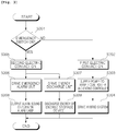
- Fig. 3 is a flowchart illustrating the operation of the emergency stop system for a hybrid excavator according to an embodiment of the present invention.
- the system supplies the power that is applied from the power supply unit to the hybrid controller and the engine controller.
- the system intercepts the power supply to the hybrid controller and the engine controller.
- the system makes the power be supplied to the other path (for example, the emergency alarm unit or the energy discharge unit).
- the other path for example, the emergency alarm unit or the energy discharge unit.
- the first electric contact 101a is turned on in the normal operation state to supply the power that is applied from the power supply unit to the hybrid controller and the engine controller.
- the first electric contact 101a is turned off to intercept the input power supply to the hybrid controller and the engine controller.
- the second electric contact 101b is turned off in the normal operation state to make the power that is applied from the power supply unit be supplied to the hybrid controller and the engine controller (S301 to S303).
- the second electric contact 101b When the emergency switch is pressed (that is, when the equipment abnormality or emergency situation occurs), the second electric contact 101b is turned to intercept the input power supply to the hybrid controller and the engine controller and to make the input power be supplied to the other path (that is, the emergency alarm unit or the energy discharge unit).
- the emergency alarm unit receives the input power.
- the emergency alarm unit produces the alarm sound or turns on the alarm lamp to notify the outside of the equipment abnormality or emergency situation.
- the power is not supplied to the energy discharge unit in the normal operation state, but the power is supplied thereto when the emergency switch is pressed, that is, when the equipment abnormality or the emergency situation occurs.
- the energy discharge unit discharges the energy of the energy storage device to make the hybrid power source vanish completely (S305 to S309).
- the power supply to the electric motor/generator controller, the swing electric motor controller, the swing electric motor parking brake, and the energy storage device contactors is intercepted in association with the interception of the power supply to the hybrid controller (S304).
- the power that is applied from the power supply unit is supplied to the hybrid controller and the engine controller, whereas when the emergency switch is pressed, the power that is supplied to the hybrid controller and the engine controller is intercepted to effectively stop the operation of the hybrid system in the case where the equipment abnormality or emergency situation occurs.
- the power supply is applied to the emergency alarm unit and the energy discharge unit to notify the operator and neighboring persons of the occurrence of the equipment abnormality and emergency situation and to make the hybrid power source vanish completely.
- the present invention can be used in the emergency stop system for a hybrid excavator.
- the power that is applied from the power supply unit is supplied to the hybrid controller and the engine controller, and when the emergency switch is pressed, the power that is supplied to the hybrid controller and the engine controller is intercepted to effectively stop the operation of the hybrid system in the case where the equipment abnormality or emergency situation occurs.
- the power supply is applied to the emergency alarm unit and the energy discharge unit to notify the operator and neighboring persons of the occurrence of the equipment abnormality and emergency situation and to make the hybrid power source vanish completely.
Landscapes
- Engineering & Computer Science (AREA)
- Mining & Mineral Resources (AREA)
- Civil Engineering (AREA)
- General Engineering & Computer Science (AREA)
- Structural Engineering (AREA)
- Chemical & Material Sciences (AREA)
- Combustion & Propulsion (AREA)
- Transportation (AREA)
- Mechanical Engineering (AREA)
- Health & Medical Sciences (AREA)
- Biomedical Technology (AREA)
- General Health & Medical Sciences (AREA)
- Automation & Control Theory (AREA)
- Power Engineering (AREA)
- Operation Control Of Excavators (AREA)
- Component Parts Of Construction Machinery (AREA)
- Hybrid Electric Vehicles (AREA)
Description
- The present invention relates to an emergency stop system for a hybrid excavator. More particularly, the present invention relates to an emergency stop system for a hybrid excavator, which makes a power supply that is applied from a power supply unit be supplied to a hybrid controller and an engine controller in a normal operation state, and makes an operation of a hybrid system be effectively stopped by intercepting the input power in the case where equipment abnormality or emergency situation occurs. Also, the present invention relates to an emergency stop system for a hybrid excavator, which makes the power be supplied to an emergency alarm unit and an energy discharge unit of the emergency stop system when the equipment abnormality or emergency situation occurs to notify an operator and neighboring persons of the occurrence of the equipment abnormality or the emergency situation and to make a hybrid power source of the hybrid excavator vanish completely.
- A typical hybrid system includes a high-voltage energy storage device, a high-voltage motor, and several controllers. This hybrid system greatly contributes to the increase of energy efficiency, but has many risks at the same time. Since an unexpected controller malfunction or trouble of high-voltage components may occur at any time to cause an operator to be placed in dangerous situations, there is a need for a system that copes with such emergency
JP-A-200045808 - Therefore, the present invention has been made to solve the above-mentioned problems occurring in the related art, and the subject to be solved by the present invention is to provide an emergency stop system for a hybrid excavator, according to claim 1, which makes an operation of a hybrid system be effectively stopped in the case where equipment abnormality or emergency situation occurs, notifies an operator and neighboring persons of the occurrence of the equipment abnormality or emergency situation, and makes a hybrid power source vanish completely.
- In accordance with one aspect of the present invention, there is provided an emergency stop system for a hybrid excavator, which includes an emergency switch notifying of equipment abnormality and emergency situation occurrence; and an emergency stop unit including a first electric contact which is turned on in a normal operation state to provide an input power supply to a hybrid controller and an engine controller and is turned off when the emergency switch is pressed to intercept the input power supply to the hybrid controller and the engine controller, and a second electric contact which is turned on when the emergency switch is pressed to provide the input power supply through another path.
- Preferably, the emergency stop system according to the aspect of the present invention may further include an emergency alarm unit connected to the second electric contact of the emergency stop unit to be driven by the input power supply applied thereto through the second electric contact when the input power supply to the hybrid controller and the engine controller is intercepted.
- Further, the emergency stop system according to the aspect of the present invention may further include an energy discharge unit connected to the second electric contact of the emergency stop unit to discharge energy of an energy storage device by the input power supply applied thereto through the second electric contact when the input power supply to the hybrid controller and the engine controller is intercepted.
- Preferably, in the emergency stop system according to the aspect of the present invention, at least one of an electric motor/generator controller, a swing electric motor controller, a swing electric motor parking brake, and energy storage device contactors, which are connected to the hybrid controller, may interlock with the input power supply, and be intercepted when the input power supply to the hybrid controller and the engine controller is intercepted.
- According to the present invention, in the normal operation state, the power that is applied from the power supply unit is supplied to the hybrid controller and the engine controller, whereas when the emergency switch is pressed, the power that is supplied to the hybrid controller and the engine controller is intercepted to effectively stop the operation of the hybrid system in the case where the equipment abnormality or emergency situation occurs.
- Further, when the emergency switch is pressed, the power supply is applied to the emergency alarm unit and the energy discharge unit to notify the operator and neighboring persons of the occurrence of the equipment abnormality and emergency situation and to make the hybrid power source vanish completely.
- The above objects, other features and advantages of the present invention will become more apparent by describing the preferred embodiments thereof with reference to the accompanying drawings, in which:
-
Fig. 1 is a block diagram illustrating the configuration of an emergency stop system for a hybrid excavator according to an embodiment of the present invention; -
Fig. 2 is a diagram illustrating an emergency stop unit according to an embodiment of the present invention; and -
Fig. 3 is a flowchart illustrating the operation of an emergency stop system for a hybrid excavator according to an embodiment of the present invention. -
- 101:
- emergency switch
- 102:
- power supply unit
- 103:
- engine controller
- 104:
- hybrid controller
- 105:
- emergency stop unit
- 106:
- emergency alarm unit
- 107:
- energy discharge unit
- 108:
- electric motor/generator controller
- 109:
- swing electric motor controller
- 110:
- swing electric motor parking brake
- 111:
- energy storage device contactor
-
Fig. 1 is a block diagram illustrating the configuration of an emergency stop system for a hybrid excavator according to an embodiment of the present invention. - As illustrated in
Fig. 1 , an emergency stop system for a hybrid excavator according to an embodiment of the present invention includes anemergency switch 101; anemergency stop unit 105 providing an electric power that is applied from apower supply unit 102 to anengine controller 103 and ahybrid controller 104 in a normal operation state, and intercepting the power supply to theengine controller 103 and thehybrid controller 104 and making the power applied to another path (for example, an emergency alarm unit or an energy discharge unit) when theemergency switch 101 is pressed (that is, in the case where equipment abnormality or emergency situation occurs); theemergency alarm unit 106 that is driven by the power applied thereto; and theenergy discharge unit 107. - In addition, the power supply to an electric motor/
generator controller 108, a swingelectric motor controller 109, a swing electricmotor parking brake 110, and energystorage device contactors 111, which are connected to thehybrid controller 104, is intercepted in association with the power supply interception when the power supply to thehybrid controller 104 is intercepted. - Here, the
emergency switch 101 is a switch that is pressed, for example, according to an operator's key operation in the case where the equipment abnormality or emergency situation occurs, and is located on an operator's seat to promptly cope with the emergency situation. - The
emergency stop unit 105 provides the power that is applied from thepower supply unit 102 to thehybrid controller 104 and theengine controller 103 in a normal operation state, and intercepts the power supply to thehybrid controller 104 and theengine controller 103 and makes the power supplied to another path (for example, the emergency alarm unit or the energy discharge unit) when theemergency switch 101 is pressed. Accordingly, if the equipment abnormality or emergency situation occurs, the operation of the hybrid system can be effectively stopped, and the operator and neighboring persons can be notified of the occurrence of the equipment abnormality and emergency situation. - The
emergency alarm unit 106 is configured so that the power is not supplied to theemergency alarm unit 106 in the normal operation state, but the power is supplied thereto when theemergency switch 101 is pressed, that is, when the equipment abnormality or the emergency situation occurs. If the power is supplied to theemergency alarm unit 106, the power being supplied to thehybrid controller 104 and theengine controller 103 is intercepted, and theemergency alarm unit 106 produces an alarm sound or turns on an alarm lamp to notify the outside of the equipment abnormality or emergency situation. - The
energy discharge unit 107 is also configured so that the power is not supplied to theenergy discharge unit 107 in the normal operation state, but the power is supplied thereto when theemergency switch 101 is pressed, that is, when the equipment abnormality or the emergency situation occurs. If the power is supplied to theenergy discharge unit 107, theenergy discharge unit 107 discharges energy of the energy storage device to make the hybrid power source vanish completely. - The electric motor/
generator controller 108, the swingelectric motor controller 109, the swing electricmotor parking brake 110, and the energystorage device contactors 111 are configured so that the power supply thereto is intercepted in association with the interception of the power supply to thehybrid controller 104. As a result, the operations of the hybrid electric motor controller and the swing electric motor are physically stopped, and connections between the high-voltage energy storage device and the hybrid electric motors are intercepted. - Hereinafter, an example of the emergency stop unit will be described with reference to
FIG. 2 . -
Fig. 2 is a diagram illustrating the emergency stop unit according to a preferred embodiment of the present invention. - As illustrated in
FIG. 2 , theemergency stop unit 105 according to this embodiment includes a firstelectric contact 101a which is turned on in the normal operation state to supply the input power to thehybrid controller 104 and theengine controller 103, and is turned off when theemergency switch 101 is pressed to intercept the input power to thehybrid controller 104 and theengine controller 103, and a secondelectric contact 101b which is turned on when theemergency switch 101 is pressed to supply the input power supply to another path (for example, the emergency alarm unit or the energy discharge unit). - The first
electric contact 101a is turned on in the normal operation state to supply the power that is applied from thepower supply unit 102 to thehybrid controller 104 and theengine controller 103, and is turned off when theemergency switch 101 is pressed (that is, when the equipment abnormality or emergency situation occurs) to intercept the input power supply to thehybrid controller 104 and theengine controller 103. - The second
electric contact 101b is turned off in the normal operation state to make the power that is applied from thepower supply unit 102 supplied to thehybrid controller 104 and theengine controller 103, and is turned on when theemergency switch 101 is pressed (that is, when the equipment abnormality or emergency situation occurs) to intercept the input power supply to thehybrid controller 104 and theengine controller 103 and to make the input power be supplied to the other path (that is, the emergency alarm unit or the energy discharge unit). - The operation of the emergency stop system for a hybrid excavator using the emergency stop unit having the above-described configuration in
FIG. 1 according to an embodiment of the present invention will be described with reference toFIG. 3 . -
Fig. 3 is a flowchart illustrating the operation of the emergency stop system for a hybrid excavator according to an embodiment of the present invention. - First, when the emergency stop unit normally operates, the system supplies the power that is applied from the power supply unit to the hybrid controller and the engine controller.
- By contrast, when the emergency switch is pressed, the system intercepts the power supply to the hybrid controller and the engine controller.
- Then, the system makes the power be supplied to the other path (for example, the emergency alarm unit or the energy discharge unit).
- The details thereof are as follows.
- The first
electric contact 101a is turned on in the normal operation state to supply the power that is applied from the power supply unit to the hybrid controller and the engine controller. - When the emergency switch is pressed (that is, when the equipment abnormality or emergency situation occurs), the first
electric contact 101a is turned off to intercept the input power supply to the hybrid controller and the engine controller. - On the other hand, the second
electric contact 101b is turned off in the normal operation state to make the power that is applied from the power supply unit be supplied to the hybrid controller and the engine controller (S301 to S303). - When the emergency switch is pressed (that is, when the equipment abnormality or emergency situation occurs), the second
electric contact 101b is turned to intercept the input power supply to the hybrid controller and the engine controller and to make the input power be supplied to the other path (that is, the emergency alarm unit or the energy discharge unit). - If the input power is supplied to the other path as the emergency switch is pressed (that is, as the equipment abnormality or emergency situation occurs), the emergency alarm unit receives the input power.
- Then, the emergency alarm unit produces the alarm sound or turns on the alarm lamp to notify the outside of the equipment abnormality or emergency situation.
- At this time, the power supply to the hybrid controller and the engine controller is intercepted.
- In addition, the power is not supplied to the energy discharge unit in the normal operation state, but the power is supplied thereto when the emergency switch is pressed, that is, when the equipment abnormality or the emergency situation occurs.
- If the power is supplied to the energy discharge unit, the energy discharge unit discharges the energy of the energy storage device to make the hybrid power source vanish completely (S305 to S309).
- On the other hand, the power supply to the electric motor/generator controller, the swing electric motor controller, the swing electric motor parking brake, and the energy storage device contactors is intercepted in association with the interception of the power supply to the hybrid controller (S304).
- As a result, the operations of the hybrid electric motor controller and the swing electric motor are physically stopped, and the connections between the high-voltage energy storage device and the hybrid electric motors are intercepted.
- As described above, according to the present invention, in the normal operation state, the power that is applied from the power supply unit is supplied to the hybrid controller and the engine controller, whereas when the emergency switch is pressed, the power that is supplied to the hybrid controller and the engine controller is intercepted to effectively stop the operation of the hybrid system in the case where the equipment abnormality or emergency situation occurs.
- Further, when the emergency switch is pressed, the power supply is applied to the emergency alarm unit and the energy discharge unit to notify the operator and neighboring persons of the occurrence of the equipment abnormality and emergency situation and to make the hybrid power source vanish completely.
- The present invention can be used in the emergency stop system for a hybrid excavator. In the normal operation state, the power that is applied from the power supply unit is supplied to the hybrid controller and the engine controller, and when the emergency switch is pressed, the power that is supplied to the hybrid controller and the engine controller is intercepted to effectively stop the operation of the hybrid system in the case where the equipment abnormality or emergency situation occurs. When the emergency switch is pressed, the power supply is applied to the emergency alarm unit and the energy discharge unit to notify the operator and neighboring persons of the occurrence of the equipment abnormality and emergency situation and to make the hybrid power source vanish completely.
Claims (3)
- An emergency stop system for a hybrid excavator comprising:an emergency switch (101) notifying of equipment abnormality and emergency situation occurrence;an emergency stop unit (105) including a first contact which is turned on in a normal operation state to provide an input power supply to a hybrid controller (104, S304) and an engine controller (103) and is turned off when the emergency switch (101) is pressed to intercept the input power supply to the hybrid controller (104, S340) and the engine controller (103), and a second contact (101B) which is turned on when the emergency switch (101) is pressed to provide the input power supply through another path; andan energy discharge unit (107) connected to the second contact (101B) of the emergency stop unit (105) to discharge energy of an energy storage device by the input power supply applied thereto through the second contact (191B) when the input power supply to the hybrid controller (104) and the engine controller (103) is intercepted.
- The emergency stop system according to claim 1, further comprising an emergency alarm unit (106) connected to the second contact (101B) of the emergency stop unit (105) to be driven by the input power supply applied thereto through the second contact (101B) when the input power supply to the hybrid controller (104) and the engine controller (103) is intercepted.
- The emergency stop system according to claim 1, wherein at least one of an electric motor/generator controller (108), a swing electric motor controller (109), a swing electric motor parking brake (119), and energy storage device contactors, which are connected to the hybrid controller (104), interlocks with the input power supply, and is intercepted when the input power supply to the hybrid controller (104) and the engine controller (103) is intercepted.
Applications Claiming Priority (1)
| Application Number | Priority Date | Filing Date | Title |
|---|---|---|---|
| PCT/KR2010/004760 WO2012011618A1 (en) | 2010-07-21 | 2010-07-21 | Emergency stop system for a hybrid excavator |
Publications (4)
| Publication Number | Publication Date |
|---|---|
| EP2597212A1 EP2597212A1 (en) | 2013-05-29 |
| EP2597212A4 EP2597212A4 (en) | 2015-02-18 |
| EP2597212B1 true EP2597212B1 (en) | 2016-04-06 |
| EP2597212B8 EP2597212B8 (en) | 2016-08-24 |
Family
ID=45497021
Family Applications (1)
| Application Number | Title | Priority Date | Filing Date |
|---|---|---|---|
| EP10855046.8A Not-in-force EP2597212B8 (en) | 2010-07-21 | 2010-07-21 | Emergency stop system for a hybrid excavator |
Country Status (6)
| Country | Link |
|---|---|
| US (1) | US9230761B2 (en) |
| EP (1) | EP2597212B8 (en) |
| JP (1) | JP5767702B2 (en) |
| KR (1) | KR101763279B1 (en) |
| CN (1) | CN103025968B (en) |
| WO (1) | WO2012011618A1 (en) |
Families Citing this family (11)
| Publication number | Priority date | Publication date | Assignee | Title |
|---|---|---|---|---|
| US9024565B2 (en) | 2011-03-23 | 2015-05-05 | Volvo Construction Equipment Ab | Anti-rebounding control apparatus and method in an electrical swing system of a hybrid excavator |
| WO2015107663A1 (en) * | 2014-01-16 | 2015-07-23 | 株式会社小松製作所 | Emergency stop system for work machine, work machine, and emergency stop method for work machine |
| US10144410B2 (en) | 2014-04-24 | 2018-12-04 | Volvo Construction Equipment Ab | Apparatus for calculating operational time of hybrid construction machine and method therefor |
| WO2015178516A1 (en) * | 2014-05-20 | 2015-11-26 | 볼보 컨스트럭션 이큅먼트 에이비 | Power control device for construction machine |
| JP6443423B2 (en) | 2016-10-14 | 2018-12-26 | コベルコ建機株式会社 | Construction machinery |
| CN106394436A (en) * | 2016-11-02 | 2017-02-15 | 安徽华菱汽车有限公司 | Vehicle power supply safety optimization method and device |
| US10454392B2 (en) | 2016-11-11 | 2019-10-22 | Hubbell Incorporated | Motor drive and method of emergency stop braking |
| EP3861176B1 (en) * | 2018-10-02 | 2023-03-29 | Volvo Construction Equipment AB | Device for controlling working unit of construction equipment |
| JP7380272B2 (en) * | 2020-02-04 | 2023-11-15 | トヨタ自動車株式会社 | vehicle |
| KR102378366B1 (en) * | 2020-10-13 | 2022-03-25 | 주식회사 새한산업 | Safety fence facility |
| CN117087437A (en) * | 2023-08-08 | 2023-11-21 | 中国北方车辆研究所 | A hybrid vehicle emergency power-off control device and method |
Family Cites Families (15)
| Publication number | Priority date | Publication date | Assignee | Title |
|---|---|---|---|---|
| JPH03107332A (en) * | 1989-09-21 | 1991-05-07 | Kobe Steel Ltd | Dc power supply device for servo |
| US5422808A (en) * | 1993-04-20 | 1995-06-06 | Anthony T. Catanese, Jr. | Method and apparatus for fail-safe control of at least one electro-mechanical or electro-hydraulic component |
| JPH08152240A (en) * | 1994-11-29 | 1996-06-11 | Seirei Ind Co Ltd | Crusher overload detection device for self-propelled ice-ice device |
| EP0863522B1 (en) * | 1997-03-03 | 2005-09-14 | REMA Lipprandt GmbH & Co. KG | Emergency switching device, in particular for load-handling trucks, to interrupt the connection between a motor or its control unit and the batteries |
| JP3650846B2 (en) | 1997-04-23 | 2005-05-25 | 株式会社鈴機商事 | Construction machine with power supply |
| JP3098990B2 (en) * | 1998-03-03 | 2000-10-16 | 住友建機株式会社 | Crane specification hydraulic excavator alarm system |
| JP3752079B2 (en) * | 1998-07-30 | 2006-03-08 | 新キャタピラー三菱株式会社 | Emergency stop circuit of machine |
| US6409457B1 (en) * | 1999-10-15 | 2002-06-25 | George Korycan | Work vehicle |
| JP2002173299A (en) * | 2000-12-07 | 2002-06-21 | Tcm Corp | Emergency stop device for industrial vehicle |
| KR100621979B1 (en) * | 2004-03-22 | 2006-09-14 | 볼보 컨스트럭션 이키프먼트 홀딩 스웨덴 에이비 | Operating lever malfunction prevention system |
| JP4468047B2 (en) * | 2004-04-02 | 2010-05-26 | コベルコ建機株式会社 | Emergency turning brake device for work machines |
| JP2006224772A (en) * | 2005-02-16 | 2006-08-31 | Toyota Motor Corp | Vehicle power supply |
| KR200441679Y1 (en) * | 2007-02-06 | 2008-09-04 | 이원재 | Assembly for forced open contact |
| JP4750067B2 (en) * | 2007-03-30 | 2011-08-17 | 株式会社小松製作所 | Construction machine emergency stop system and construction machine |
| CN102272389B (en) * | 2009-01-07 | 2015-01-21 | 住友重机械工业株式会社 | Warming up method of hybrid construction machine and hybrid construction machine |
-
2010
- 2010-07-21 JP JP2013520627A patent/JP5767702B2/en not_active Expired - Fee Related
- 2010-07-21 KR KR1020127033043A patent/KR101763279B1/en not_active Expired - Fee Related
- 2010-07-21 WO PCT/KR2010/004760 patent/WO2012011618A1/en not_active Ceased
- 2010-07-21 US US13/811,105 patent/US9230761B2/en not_active Expired - Fee Related
- 2010-07-21 CN CN201080068139.XA patent/CN103025968B/en not_active Expired - Fee Related
- 2010-07-21 EP EP10855046.8A patent/EP2597212B8/en not_active Not-in-force
Non-Patent Citations (1)
| Title |
|---|
| None * |
Also Published As
| Publication number | Publication date |
|---|---|
| KR101763279B1 (en) | 2017-07-31 |
| CN103025968B (en) | 2015-05-06 |
| US9230761B2 (en) | 2016-01-05 |
| WO2012011618A1 (en) | 2012-01-26 |
| EP2597212B8 (en) | 2016-08-24 |
| EP2597212A4 (en) | 2015-02-18 |
| JP2013536333A (en) | 2013-09-19 |
| EP2597212A1 (en) | 2013-05-29 |
| JP5767702B2 (en) | 2015-08-19 |
| KR20130050307A (en) | 2013-05-15 |
| CN103025968A (en) | 2013-04-03 |
| US20130119784A1 (en) | 2013-05-16 |
Similar Documents
| Publication | Publication Date | Title |
|---|---|---|
| US9230761B2 (en) | Emergency stop system for a hybrid excavator | |
| EP2850717B1 (en) | Elevator backup power supply | |
| EP3515747B1 (en) | Hazardous voltage interlock loop system | |
| CN107234969B (en) | Electric vehicle and its high voltage protection device | |
| US11590847B2 (en) | Disconnection of vehicle electric system using low voltage switch | |
| CN102545375B (en) | Automatic switching on/off method for emergency power supply of power plant | |
| CN110641282A (en) | Fuel cell system for exhausting remaining power in emergency | |
| CN206394446U (en) | Safety device, electrical component and electricity or motor vehicle driven by mixed power | |
| CN103072485A (en) | High-voltage interlocking circuit of electric automobile | |
| EP3196912B1 (en) | Switch | |
| CN102514495A (en) | Structure for high voltage safety protection system during collision of electric automobiles and method for same | |
| CN113805475B (en) | Safety control loop | |
| CN108352273A (en) | equipment for switching circuits | |
| CN103061903A (en) | System and method for emergent shutdown | |
| JP2014131486A (en) | Vehicle control device and failure determination method | |
| CN202370724U (en) | Engine starting device and power system | |
| CN102844955B (en) | Be separated the turn-off apparatus of source of electrical energy and load and there is the Circuits System of turn-off apparatus | |
| CN117614086A (en) | Battery control box and control method, battery management system and energy storage system | |
| CN117048351A (en) | Power supply control system, power supply control method, equipment and medium for dual-stream vehicles | |
| JP4643333B2 (en) | Electric vehicle control device | |
| JP6590149B2 (en) | Power control device | |
| CN119812405B (en) | Marine fuel cell containing emergency shutdown system ESD and control method thereof | |
| JP2015058784A (en) | Vehicle power supply | |
| CN116160862A (en) | Electric vehicle and active discharge control method, device and system thereof | |
| Minav et al. | SAFETY OF ZONAL HYDRAULICS IN NON-ROAD MOBILE MACHINERY |
Legal Events
| Date | Code | Title | Description |
|---|---|---|---|
| PUAI | Public reference made under article 153(3) epc to a published international application that has entered the european phase |
Free format text: ORIGINAL CODE: 0009012 |
|
| 17P | Request for examination filed |
Effective date: 20130117 |
|
| AK | Designated contracting states |
Kind code of ref document: A1 Designated state(s): AL AT BE BG CH CY CZ DE DK EE ES FI FR GB GR HR HU IE IS IT LI LT LU LV MC MK MT NL NO PL PT RO SE SI SK SM TR |
|
| RIN1 | Information on inventor provided before grant (corrected) |
Inventor name: KIM, EUI-CHUL Inventor name: KIM, JI-YUN Inventor name: CHOI, DONG-UK |
|
| DAX | Request for extension of the european patent (deleted) | ||
| RIN1 | Information on inventor provided before grant (corrected) |
Inventor name: KIM, EUI-CHUL Inventor name: KIM, JI-YUN Inventor name: CHOI, DONG-UK |
|
| A4 | Supplementary search report drawn up and despatched |
Effective date: 20150119 |
|
| RIC1 | Information provided on ipc code assigned before grant |
Ipc: B60W 20/00 20060101ALI20150113BHEP Ipc: B60W 10/08 20060101ALI20150113BHEP Ipc: E02F 9/24 20060101AFI20150113BHEP Ipc: E02F 9/20 20060101ALI20150113BHEP Ipc: E02F 9/26 20060101ALI20150113BHEP Ipc: B60W 10/26 20060101ALI20150113BHEP Ipc: H01H 35/00 20060101ALI20150113BHEP |
|
| GRAP | Despatch of communication of intention to grant a patent |
Free format text: ORIGINAL CODE: EPIDOSNIGR1 |
|
| INTG | Intention to grant announced |
Effective date: 20150924 |
|
| REG | Reference to a national code |
Ref country code: DE Ref legal event code: R079 Ref document number: 602010032144 Country of ref document: DE Free format text: PREVIOUS MAIN CLASS: E02F0009240000 Ipc: B60W0020500000 |
|
| GRAS | Grant fee paid |
Free format text: ORIGINAL CODE: EPIDOSNIGR3 |
|
| GRAA | (expected) grant |
Free format text: ORIGINAL CODE: 0009210 |
|
| RIC1 | Information provided on ipc code assigned before grant |
Ipc: E02F 9/26 20060101ALI20160201BHEP Ipc: B60W 10/26 20060101ALI20160201BHEP Ipc: E02F 9/24 20060101ALI20160201BHEP Ipc: H01H 35/00 20060101ALI20160201BHEP Ipc: B60W 20/50 20160101AFI20160201BHEP Ipc: B60W 10/08 20060101ALI20160201BHEP Ipc: E02F 9/20 20060101ALI20160201BHEP |
|
| INTG | Intention to grant announced |
Effective date: 20160217 |
|
| RIN1 | Information on inventor provided before grant (corrected) |
Inventor name: CHOI, DONG-UK Inventor name: KIM, EUI-CHUL Inventor name: KIM, JI-YUN |
|
| AK | Designated contracting states |
Kind code of ref document: B1 Designated state(s): AL AT BE BG CH CY CZ DE DK EE ES FI FR GB GR HR HU IE IS IT LI LT LU LV MC MK MT NL NO PL PT RO SE SI SK SM TR |
|
| REG | Reference to a national code |
Ref country code: GB Ref legal event code: FG4D |
|
| REG | Reference to a national code |
Ref country code: AT Ref legal event code: REF Ref document number: 787431 Country of ref document: AT Kind code of ref document: T Effective date: 20160415 Ref country code: CH Ref legal event code: EP |
|
| REG | Reference to a national code |
Ref country code: IE Ref legal event code: FG4D |
|
| REG | Reference to a national code |
Ref country code: DE Ref legal event code: R096 Ref document number: 602010032144 Country of ref document: DE |
|
| RIN2 | Information on inventor provided after grant (corrected) |
Inventor name: KIM, JI-YUN Inventor name: CHOI, DONG-UK Inventor name: KIM, EUI-CHUL |
|
| REG | Reference to a national code |
Ref country code: LT Ref legal event code: MG4D Ref country code: NL Ref legal event code: MP Effective date: 20160406 |
|
| REG | Reference to a national code |
Ref country code: AT Ref legal event code: MK05 Ref document number: 787431 Country of ref document: AT Kind code of ref document: T Effective date: 20160406 |
|
| PG25 | Lapsed in a contracting state [announced via postgrant information from national office to epo] |
Ref country code: NL Free format text: LAPSE BECAUSE OF FAILURE TO SUBMIT A TRANSLATION OF THE DESCRIPTION OR TO PAY THE FEE WITHIN THE PRESCRIBED TIME-LIMIT Effective date: 20160406 |
|
| PG25 | Lapsed in a contracting state [announced via postgrant information from national office to epo] |
Ref country code: NO Free format text: LAPSE BECAUSE OF FAILURE TO SUBMIT A TRANSLATION OF THE DESCRIPTION OR TO PAY THE FEE WITHIN THE PRESCRIBED TIME-LIMIT Effective date: 20160706 Ref country code: FI Free format text: LAPSE BECAUSE OF FAILURE TO SUBMIT A TRANSLATION OF THE DESCRIPTION OR TO PAY THE FEE WITHIN THE PRESCRIBED TIME-LIMIT Effective date: 20160406 Ref country code: IS Free format text: LAPSE BECAUSE OF FAILURE TO SUBMIT A TRANSLATION OF THE DESCRIPTION OR TO PAY THE FEE WITHIN THE PRESCRIBED TIME-LIMIT Effective date: 20160806 Ref country code: PL Free format text: LAPSE BECAUSE OF FAILURE TO SUBMIT A TRANSLATION OF THE DESCRIPTION OR TO PAY THE FEE WITHIN THE PRESCRIBED TIME-LIMIT Effective date: 20160406 Ref country code: LT Free format text: LAPSE BECAUSE OF FAILURE TO SUBMIT A TRANSLATION OF THE DESCRIPTION OR TO PAY THE FEE WITHIN THE PRESCRIBED TIME-LIMIT Effective date: 20160406 |
|
| PG25 | Lapsed in a contracting state [announced via postgrant information from national office to epo] |
Ref country code: LV Free format text: LAPSE BECAUSE OF FAILURE TO SUBMIT A TRANSLATION OF THE DESCRIPTION OR TO PAY THE FEE WITHIN THE PRESCRIBED TIME-LIMIT Effective date: 20160406 Ref country code: PT Free format text: LAPSE BECAUSE OF FAILURE TO SUBMIT A TRANSLATION OF THE DESCRIPTION OR TO PAY THE FEE WITHIN THE PRESCRIBED TIME-LIMIT Effective date: 20160808 Ref country code: AT Free format text: LAPSE BECAUSE OF FAILURE TO SUBMIT A TRANSLATION OF THE DESCRIPTION OR TO PAY THE FEE WITHIN THE PRESCRIBED TIME-LIMIT Effective date: 20160406 Ref country code: HR Free format text: LAPSE BECAUSE OF FAILURE TO SUBMIT A TRANSLATION OF THE DESCRIPTION OR TO PAY THE FEE WITHIN THE PRESCRIBED TIME-LIMIT Effective date: 20160406 Ref country code: SE Free format text: LAPSE BECAUSE OF FAILURE TO SUBMIT A TRANSLATION OF THE DESCRIPTION OR TO PAY THE FEE WITHIN THE PRESCRIBED TIME-LIMIT Effective date: 20160406 Ref country code: GR Free format text: LAPSE BECAUSE OF FAILURE TO SUBMIT A TRANSLATION OF THE DESCRIPTION OR TO PAY THE FEE WITHIN THE PRESCRIBED TIME-LIMIT Effective date: 20160707 Ref country code: ES Free format text: LAPSE BECAUSE OF FAILURE TO SUBMIT A TRANSLATION OF THE DESCRIPTION OR TO PAY THE FEE WITHIN THE PRESCRIBED TIME-LIMIT Effective date: 20160406 |
|
| PG25 | Lapsed in a contracting state [announced via postgrant information from national office to epo] |
Ref country code: BE Free format text: LAPSE BECAUSE OF FAILURE TO SUBMIT A TRANSLATION OF THE DESCRIPTION OR TO PAY THE FEE WITHIN THE PRESCRIBED TIME-LIMIT Effective date: 20160406 |
|
| REG | Reference to a national code |
Ref country code: DE Ref legal event code: R097 Ref document number: 602010032144 Country of ref document: DE |
|
| REG | Reference to a national code |
Ref country code: FR Ref legal event code: PLFP Year of fee payment: 7 |
|
| PG25 | Lapsed in a contracting state [announced via postgrant information from national office to epo] |
Ref country code: RO Free format text: LAPSE BECAUSE OF FAILURE TO SUBMIT A TRANSLATION OF THE DESCRIPTION OR TO PAY THE FEE WITHIN THE PRESCRIBED TIME-LIMIT Effective date: 20160406 Ref country code: SK Free format text: LAPSE BECAUSE OF FAILURE TO SUBMIT A TRANSLATION OF THE DESCRIPTION OR TO PAY THE FEE WITHIN THE PRESCRIBED TIME-LIMIT Effective date: 20160406 Ref country code: DK Free format text: LAPSE BECAUSE OF FAILURE TO SUBMIT A TRANSLATION OF THE DESCRIPTION OR TO PAY THE FEE WITHIN THE PRESCRIBED TIME-LIMIT Effective date: 20160406 Ref country code: CZ Free format text: LAPSE BECAUSE OF FAILURE TO SUBMIT A TRANSLATION OF THE DESCRIPTION OR TO PAY THE FEE WITHIN THE PRESCRIBED TIME-LIMIT Effective date: 20160406 Ref country code: EE Free format text: LAPSE BECAUSE OF FAILURE TO SUBMIT A TRANSLATION OF THE DESCRIPTION OR TO PAY THE FEE WITHIN THE PRESCRIBED TIME-LIMIT Effective date: 20160406 |
|
| PLBE | No opposition filed within time limit |
Free format text: ORIGINAL CODE: 0009261 |
|
| STAA | Information on the status of an ep patent application or granted ep patent |
Free format text: STATUS: NO OPPOSITION FILED WITHIN TIME LIMIT |
|
| PG25 | Lapsed in a contracting state [announced via postgrant information from national office to epo] |
Ref country code: SM Free format text: LAPSE BECAUSE OF FAILURE TO SUBMIT A TRANSLATION OF THE DESCRIPTION OR TO PAY THE FEE WITHIN THE PRESCRIBED TIME-LIMIT Effective date: 20160406 |
|
| REG | Reference to a national code |
Ref country code: CH Ref legal event code: PL |
|
| 26N | No opposition filed |
Effective date: 20170110 |
|
| PG25 | Lapsed in a contracting state [announced via postgrant information from national office to epo] |
Ref country code: MC Free format text: LAPSE BECAUSE OF FAILURE TO SUBMIT A TRANSLATION OF THE DESCRIPTION OR TO PAY THE FEE WITHIN THE PRESCRIBED TIME-LIMIT Effective date: 20160406 |
|
| PG25 | Lapsed in a contracting state [announced via postgrant information from national office to epo] |
Ref country code: LI Free format text: LAPSE BECAUSE OF NON-PAYMENT OF DUE FEES Effective date: 20160731 Ref country code: CH Free format text: LAPSE BECAUSE OF NON-PAYMENT OF DUE FEES Effective date: 20160731 |
|
| REG | Reference to a national code |
Ref country code: IE Ref legal event code: MM4A |
|
| PG25 | Lapsed in a contracting state [announced via postgrant information from national office to epo] |
Ref country code: SI Free format text: LAPSE BECAUSE OF FAILURE TO SUBMIT A TRANSLATION OF THE DESCRIPTION OR TO PAY THE FEE WITHIN THE PRESCRIBED TIME-LIMIT Effective date: 20160406 |
|
| PGFP | Annual fee paid to national office [announced via postgrant information from national office to epo] |
Ref country code: GB Payment date: 20170125 Year of fee payment: 7 |
|
| REG | Reference to a national code |
Ref country code: FR Ref legal event code: PLFP Year of fee payment: 8 |
|
| PG25 | Lapsed in a contracting state [announced via postgrant information from national office to epo] |
Ref country code: IE Free format text: LAPSE BECAUSE OF NON-PAYMENT OF DUE FEES Effective date: 20160721 |
|
| PG25 | Lapsed in a contracting state [announced via postgrant information from national office to epo] |
Ref country code: LU Free format text: LAPSE BECAUSE OF NON-PAYMENT OF DUE FEES Effective date: 20160721 |
|
| PGFP | Annual fee paid to national office [announced via postgrant information from national office to epo] |
Ref country code: IT Payment date: 20170127 Year of fee payment: 7 |
|
| GBPC | Gb: european patent ceased through non-payment of renewal fee |
Effective date: 20170721 |
|
| PG25 | Lapsed in a contracting state [announced via postgrant information from national office to epo] |
Ref country code: GB Free format text: LAPSE BECAUSE OF NON-PAYMENT OF DUE FEES Effective date: 20170721 |
|
| PG25 | Lapsed in a contracting state [announced via postgrant information from national office to epo] |
Ref country code: CY Free format text: LAPSE BECAUSE OF FAILURE TO SUBMIT A TRANSLATION OF THE DESCRIPTION OR TO PAY THE FEE WITHIN THE PRESCRIBED TIME-LIMIT Effective date: 20160406 Ref country code: HU Free format text: LAPSE BECAUSE OF FAILURE TO SUBMIT A TRANSLATION OF THE DESCRIPTION OR TO PAY THE FEE WITHIN THE PRESCRIBED TIME-LIMIT; INVALID AB INITIO Effective date: 20100721 |
|
| PG25 | Lapsed in a contracting state [announced via postgrant information from national office to epo] |
Ref country code: MT Free format text: LAPSE BECAUSE OF NON-PAYMENT OF DUE FEES Effective date: 20160731 Ref country code: MK Free format text: LAPSE BECAUSE OF FAILURE TO SUBMIT A TRANSLATION OF THE DESCRIPTION OR TO PAY THE FEE WITHIN THE PRESCRIBED TIME-LIMIT Effective date: 20160406 Ref country code: TR Free format text: LAPSE BECAUSE OF FAILURE TO SUBMIT A TRANSLATION OF THE DESCRIPTION OR TO PAY THE FEE WITHIN THE PRESCRIBED TIME-LIMIT Effective date: 20160406 |
|
| REG | Reference to a national code |
Ref country code: FR Ref legal event code: PLFP Year of fee payment: 9 |
|
| PG25 | Lapsed in a contracting state [announced via postgrant information from national office to epo] |
Ref country code: BG Free format text: LAPSE BECAUSE OF FAILURE TO SUBMIT A TRANSLATION OF THE DESCRIPTION OR TO PAY THE FEE WITHIN THE PRESCRIBED TIME-LIMIT Effective date: 20160406 |
|
| PG25 | Lapsed in a contracting state [announced via postgrant information from national office to epo] |
Ref country code: IT Free format text: LAPSE BECAUSE OF NON-PAYMENT OF DUE FEES Effective date: 20170721 |
|
| PG25 | Lapsed in a contracting state [announced via postgrant information from national office to epo] |
Ref country code: AL Free format text: LAPSE BECAUSE OF FAILURE TO SUBMIT A TRANSLATION OF THE DESCRIPTION OR TO PAY THE FEE WITHIN THE PRESCRIBED TIME-LIMIT Effective date: 20160406 |
|
| PGFP | Annual fee paid to national office [announced via postgrant information from national office to epo] |
Ref country code: DE Payment date: 20190718 Year of fee payment: 10 Ref country code: FR Payment date: 20190715 Year of fee payment: 10 |
|
| REG | Reference to a national code |
Ref country code: DE Ref legal event code: R119 Ref document number: 602010032144 Country of ref document: DE |
|
| PG25 | Lapsed in a contracting state [announced via postgrant information from national office to epo] |
Ref country code: FR Free format text: LAPSE BECAUSE OF NON-PAYMENT OF DUE FEES Effective date: 20200731 |
|
| PG25 | Lapsed in a contracting state [announced via postgrant information from national office to epo] |
Ref country code: DE Free format text: LAPSE BECAUSE OF NON-PAYMENT OF DUE FEES Effective date: 20210202 |