EP2596904B1 - Positionsgenau variable Stringerpositionierung - Google Patents
Positionsgenau variable Stringerpositionierung Download PDFInfo
- Publication number
- EP2596904B1 EP2596904B1 EP11190192.2A EP11190192A EP2596904B1 EP 2596904 B1 EP2596904 B1 EP 2596904B1 EP 11190192 A EP11190192 A EP 11190192A EP 2596904 B1 EP2596904 B1 EP 2596904B1
- Authority
- EP
- European Patent Office
- Prior art keywords
- joining tool
- profile body
- profile
- joining
- industrial robot
- Prior art date
- Legal status (The legal status is an assumption and is not a legal conclusion. Google has not performed a legal analysis and makes no representation as to the accuracy of the status listed.)
- Active
Links
Images


Classifications
-
- B—PERFORMING OPERATIONS; TRANSPORTING
- B23—MACHINE TOOLS; METAL-WORKING NOT OTHERWISE PROVIDED FOR
- B23P—METAL-WORKING NOT OTHERWISE PROVIDED FOR; COMBINED OPERATIONS; UNIVERSAL MACHINE TOOLS
- B23P19/00—Machines for simply fitting together or separating metal parts or objects, or metal and non-metal parts, whether or not involving some deformation; Tools or devices therefor so far as not provided for in other classes
- B23P19/04—Machines for simply fitting together or separating metal parts or objects, or metal and non-metal parts, whether or not involving some deformation; Tools or devices therefor so far as not provided for in other classes for assembling or disassembling parts
-
- B—PERFORMING OPERATIONS; TRANSPORTING
- B25—HAND TOOLS; PORTABLE POWER-DRIVEN TOOLS; MANIPULATORS
- B25J—MANIPULATORS; CHAMBERS PROVIDED WITH MANIPULATION DEVICES
- B25J11/00—Manipulators not otherwise provided for
- B25J11/005—Manipulators for mechanical processing tasks
-
- B—PERFORMING OPERATIONS; TRANSPORTING
- B23—MACHINE TOOLS; METAL-WORKING NOT OTHERWISE PROVIDED FOR
- B23P—METAL-WORKING NOT OTHERWISE PROVIDED FOR; COMBINED OPERATIONS; UNIVERSAL MACHINE TOOLS
- B23P2700/00—Indexing scheme relating to the articles being treated, e.g. manufactured, repaired, assembled, connected or other operations covered in the subgroups
- B23P2700/01—Aircraft parts
-
- B—PERFORMING OPERATIONS; TRANSPORTING
- B64—AIRCRAFT; AVIATION; COSMONAUTICS
- B64F—GROUND OR AIRCRAFT-CARRIER-DECK INSTALLATIONS SPECIALLY ADAPTED FOR USE IN CONNECTION WITH AIRCRAFT; DESIGNING, MANUFACTURING, ASSEMBLING, CLEANING, MAINTAINING OR REPAIRING AIRCRAFT, NOT OTHERWISE PROVIDED FOR; HANDLING, TRANSPORTING, TESTING OR INSPECTING AIRCRAFT COMPONENTS, NOT OTHERWISE PROVIDED FOR
- B64F5/00—Designing, manufacturing, assembling, cleaning, maintaining or repairing aircraft, not otherwise provided for; Handling, transporting, testing or inspecting aircraft components, not otherwise provided for
- B64F5/10—Manufacturing or assembling aircraft, e.g. jigs therefor
Definitions
- the invention relates to a joining tool for positionally accurate positioning of a profile body on a component by means of an industrial robot and for joining the profile body with the component by means of pivotable guide and / or pressure rollers.
- the EP 0 431 827 A2 relates to a device for automatically connecting an elastic profile to a web, for example for attaching a seal to a car door.
- the device can be connected to a robot arm and guided along with the robot arm along the contour of the car door.
- the DE 102 32 447 A1 relates to a device for joining a strip-shaped, resilient profile, for example a seal, next to a particular curved edge of a body.
- the US 2004/0093731 A1 relates to a system and a device with which structural parts can be connected to each other.
- the device can be mounted on a robot arm and has a connecting tool with two cooperating tool heads, of which one tool head has a plurality of tools for drilling holes and for inserting and deforming rivets, while the other tool head is used for the deformation of the To pick up rivets necessary forces.
- the JP 2006 131058 A relates to a device for introducing a rubber seal in a window frame of a car window.
- the DE 10 2004 056 286 A1 relates to a device for the shape and / or dimension independent merging of several individual components of a three-dimensional body, which are positioned in space to each other.
- the device comprises at least one measuring device, by means of which the position of at least one of the individual components in space can be precisely detected and moved by means of a positioning device into a predetermined position.
- the EP 2 388 194 A2 relates to a system and a device with which structural parts, such as plates and stiffening ribs or stringer, can be connected to each other.
- the invention relates to a joining tool, which is also referred to below as a tool, for positionally accurate joining a profile body, for example, a stringer, with a component.
- the component may be, for example, the cell wall of an aircraft and the profile body a so-called stringer for reinforcing or stiffening the cell wall.
- the tool has a docking port, with which it can be automatically docked with an industrial robot in a known manner and can be undocked by this.
- the tool can have a gripper with which the profile body can be gripped, for example, on a supply device or a bearing.
- the gripper is designed so that it can hold the profile body after gripping, transport it to the component and position it there.
- the tool further has a device with which the profile body can be pressed onto the top side of the component facing it, and optionally a device with which the profile body and / or the component can be activated in order to establish a permanent connection with one another.
- the tool has guide rollers which abut against the component walls projecting from the side walls or side bars of the profile body during the joining or roll on this.
- the guide rollers or their position can be automatically adapted to different shapes of a profile body and / or profile body with different shapes.
- the profile body is a stringer. Under stringer is here understood a long profile body, which can be connected to reinforce or stiffen large-scale unstable plates or other surface structures with these.
- the profile body may be a hollow profile body with an open side, wherein the open side is preferably placed on the first component and laterally outwardly projecting profile flanges or individual connection pads, via which the profile body is connected to the surface structure.
- the profile body can also be a solid body with a bottom, via which it can be connected to the surface structure.
- the gripping tool which can be controlled via the robot, is preferably designed such that it can grip profile bodies or stringer of different geometry.
- profile bodies with a hollow profile it may be sufficient that the gripper moves into the hollow profile and the hollow profile comes to rest loosely on the gripper when lifting.
- the gripper actively engages the profile body, so that it must solve a gripping and holding position with the profile body again before the start of joining.
- profile bodies with a solid profile the gripper must be able to actively grasp the profile, for example like a pair of pliers. After the positioning of the profile body on the component and the loosening of the gripper, the gripper is preferably moved with the joining tool during joining in the joining direction.
- a device is used to transport the stringer from the delivery to the second component, which engages and holds the stringer at each end with a gripper.
- the one gripper can be mitge regarding by the tool according to the invention
- the second gripper is a known gripper and is usually moved by a second industrial robot, which is connected to the tool leading industrial robot in space.
- Such a device is out of the DE 10 2010 029 094 A1 known, which is an application of the Applicant, the content of which is expressly incorporated herein by reference.
- At least one further robot can be used, which supports the profile body approximately in the middle in order to avoid a central bending or breaking off of the profile body.
- the two tools that grip and hold the profile body at the ends be designed as joining tools that run towards each other and thereby add the profile body from both sides simultaneously with the component.
- a further shortening of the production time can be achieved by further robots, each equipped with a joining tool and connected in series.
- the device for pressing the profile body or stringer is at least one Andschreibharmharm, for example, a single pressure roller.
- Only one pressure roller can be sufficient if the profile body is a solid body or a largely rigid, preferably closed on all sides hollow profile (for example, a multi, four or triangular profile and / or a rounded profile).
- the pressure roller can press on the top of the profile body and thereby press the profile body with its underside on the component.
- the use of only one pressure roller has the advantage that the introduction of force into the profile body takes place centrally when the roller runs centrally on the upper side of the profile body. In addition, contamination of the pressure roller is avoided, since they are not in the plane of Activation device is located.
- the profile body may have narrow, curved and / or tab-like Anklebestege. With a single pressure roller also curves or curved profile body or stringers are easier to handle.
- the device preferably has at least one pair of pressure rollers which press the profile edges, the gluing bar or the connection pads onto the component on both sides of the profile body.
- the tool can also have more than one pressure roller or a pair of pressure rollers in the joining direction one behind the other.
- the pressure roller or the pressure rollers may be individually rotationally driven and additionally have a linear drive which moves the roller (s) perpendicular to the component to or from it and thereby changes the contact force of the roller.
- they can have a linear drive with which they can be moved toward and away from one another in order to be adapted to profiles of different widths and / or profile body flanges or connection pads. It can or can also be arranged side by side on a common axis one or more pressure rollers, which can be lowered for pressing on the Profil Eisenlansche or connection pads, for example, or can be lowered individually.
- the device for activating the profile body and / or the component is a device which preferably permanently connects, for example by supplying heat, radiation or pressure, the underside of the profile body with its side facing the component.
- the pressing device can simultaneously also form the activation device.
- the activation device is a separate device that can be controlled independently of the pressing device.
- the profile body and / or the component may consist of a material which can be activated in the above sense, that is, allows a permanent connection between the parts, for example by supplying heat.
- the profile body and / or the component can also have an activatable layer, which is activated by the activation device and produces the permanent connection of the two parts.
- the activation device can have continuous contact with the profile edge and be active throughout the joining process.
- the activation device can be inactive when moving from one connection pad to the next connection pad and only activated when directly is above the connection pad.
- the activating device can be located at a distance above the stringer edge or connecting pad, from which it is lowered down for activating at the activation location in order to come into mating contact with the connecting pad.
- the activation device can also be laterally pivotable or guided at a constant height above the profile edge or the connection pads. It can be active during the entire joining process or clocked or switched on and off as needed.
- the activation device can be adapted to different profile body widths as described for the pressing device by means of a linear drive. If the joining tool has a pressing device and an activation device, both devices can also be adjusted by means of a common drive in directions transverse to the joining direction.
- the tool further has guide rollers which abut laterally against the projecting from the component sides of the profile body during the joining or roll on this, wherein the distance between the two guide rollers can be adapted to different geometries of the profile body.
- the guide rollers are preferably used solely for the purpose of positioning the profile body exactly on the component, that is to press the profile body immediately before joining in the exact joining position.
- the guide rollers can also take over a gripper function and grab the profile body, hold and position, especially if the profile body is a T-profile body or has another shape that can be safely gripped and held by the guide rollers.
- the guide rollers may be made of a hard material or hardened. They preferably have a convex surface, so that they only touch the profile body with a contact point on the roller surface.
- the guide rollers may be passive rollers which are rotatably mounted on an axis and are set in rotation by the movement of the joining tool. However, they can also be actively driven guide rollers with one drive per guide roller, per guide roller pair or per tool.
- the rollers In order to enable the required adaptation to different geometries, the rollers must be adjustable to each other in distance and angle of attack on the profile geometry.
- the change in the distance can be made via a single drive to which the rollers are connected.
- the drive may drive a threaded rod having two opposing threaded sections that move the two rollers toward or away from each other depending on the direction of rotation of the threaded rod.
- each roller may have its own drive.
- These two drives can both cause the above-described synchronized movement of the two roles as well as in non-symmetrical profile geometries, the two roles tuned move individually. For example, in a profile body in the form of a right triangle, which rests with a leg on the component, the two roles must take different positions. The same applies to profile bodies with sections on one or both sides changing shapes, but also in profile bodies or stringers that are not straight, but in curves.
- the rollers In addition to the linear adjustment, the rollers must also be pivotable in a direction transverse to the longitudinal direction of the profile body. This pivoting can be effected independently of the linear movement by its own, for example, electric actuator. It is preferred, however, if by suitable means such as a suitable mechanism, the linear movement of the guide rollers is automatically converted into a pivoting movement, that is, the degree of pivoting of the rollers of the linear approached position is dependent. Such a coupled movement can be achieved forcibly, for example, by means of a slotted guide in which the rollers pivotally connected to the linear drive are guided.
- the rollers can move, for example when moving together from a position in which they rest on the sides of a delta profile body, in a position in which they rest on the sides of a T-profile body, that is, linear move and pivot about an axis parallel to the longitudinal axis of the profile body. That is, the rollers are then substantially perpendicular to the T-profile body, or in other words, the rollers are substantially parallel to the surface of the component.
- the movements of the rollers can also be positively coupled by means of other known positive couplings, for example by means of a linkage, or a gear guide can move the rollers in the manner described above.
- a ball-joint guide of the rollers or cylindrically steplessly movable rollers, which are moved by connected cylinders, are also conceivable.
- rollers can adapt to different contours of the profile body and guide each profile body on both sides projecting from the component so that they the position of the profile body or the stringer on the component immediately before joining in a correction movement of the robot and so that the tool can correct.
- This inventive design of the tool already leads to a greater positional accuracy of the profile body or stringer on the component as generally known.
- the tool may additionally be equipped with a 6D force sensor which is preferably connected to the tool at the interface between robot and tool. It is a monolithic measuring body with three measuring strands at an angle of 120 °. Each strand is equipped with two semiconductor strain gauges, which detect the deformation in the micrometer range. The equipment of the tool with such a force sensor allows a further improvement of the position accuracy.
- sensors are mounted on the robot and / or the tool with which an actual position of the robot can be continuously detected by means of an external measuring system and compared with a predetermined desired position.
- the external measuring system can be an iGPS
Landscapes
- Engineering & Computer Science (AREA)
- Mechanical Engineering (AREA)
- Robotics (AREA)
- Automatic Assembly (AREA)
- Manipulator (AREA)
Description
- Die Erfindung betrifft ein Fügewerkzeug zur positionsgenauen Positionierung eines Profilkörpers auf einem Bauteil mittels eines Industrieroboters und zum Fügen des Profilkörpers mit dem Bauteil mittels verschwenkbarer Führungs- und/oder Andrückrollen.
- Im Stand der Technik sind Vorrichtungen bekannt, mit denen Stringer mit einer Positioniergenauigkeit von bis zu 99,7% mit einem Bauteil verbunden werden können. Dabei kommen Greif- und Fügewerkzeuge zum Einsatz, die einen Stringer einer bestimmten Geometrie greifen und auf dem Bauteil ablegen können. Anschließend wird der Stringer mit dem Bauteil mittels des gleichen oder eines anderen Werkzeugs gefügt. Insbesondere bei sehr langen Bauteilen entspricht diese Genauigkeit nicht mehr den Anforderungen zum Beispiel der Luftfahrtindustrie, da bei einer Länge eines Stringers von zum Beispiel 18 m eine Abweichung von bis zu 4 mm auftreten kann.
- Die
EP 0 431 827 A2 betrifft eine Vorrichtung zum automatischen Verbinden eines elastischen Profils mit einem Steg, zum Beispiel zum Anbringen einer Dichtung an einer Autotür. Die Vorrichtung kann mit einem Roboterarm verbunden und zusammen mit dem Roboterarm entlang der Kontur der Autotür geführt werden. DieDE 102 32 447 A1 betrifft eine Vorrichtung zum Fügen eines leistenförmigen, nachgiebigen Profils, beispielsweise einer Dichtung, neben einer insbesondere gekrümmten Kante eines Körpers. DieUS 2004/0093731 A1 betrifft eine Anlage und eine Vorrichtung, mit der Strukturteile miteinander verbunden werden können. Die Vorrichtung kann an einem Roboterarm befestigt werden und weist ein Verbindungswerkzeug mit zwei miteinander kooperierenden Werkzeugköpfen auf, von denen der eine Werkzeugkopf mehrere Werkzeuge zum Bohren von Löchern und zum Einsetzen und Verformen von Nieten aufweist, während der andere Werkzeugkopf dazu dient, die zur Verformung der Niete notwendigen Kräfte aufzunehmen. DieJP 2006 131058 A DE 10 2004 056 286 A1 betrifft eine Vorrichtung zum form- und/oder abmessungsunabhängigen Zusammenführen von mehreren Einzelkomponenten eines dreidimensionalen Körpers, die im Raum zueinander positionierbar sind. Die Vorrichtung umfasst wenigstens eine Messeinrichtung, mit deren Hilfe die Position wenigstens einer der Einzelkomponenten im Raum präzise erfasst und mittels einer Positioniereinrichtung in eine vorgegebene Position bewegt werden kann. DieEP 2 388 194 A2 betrifft eine Anlage und eine Vorrichtung, mit der Strukturteile, wie Platten und Versteifungsrippen oder Stringer, miteinander verbunden werden können. - Es ist eine Aufgabe der Erfindung, ein Fügewerkzeug zur Verfügung zu stellen, das Profilkörper unterschiedlicher Geometrie mit dem Bauteil positionsgenau fügen kann.
- Diese Aufgabe wird mit der Vorrichtung des Anspruchs 1 gelöst.
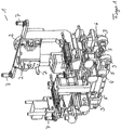
- Die Erfindung betrifft ein Fügewerkzeug, das im Folgenden auch als Werkzeug bezeichnet ist, zum positionsgenauen Fügen eines Profilkörpers, zum Beispiel eines Stringers, mit einem Bauteil. Das Bauteil kann beispielsweise die Zellenwand eines Luftfahrzeugs und der Profilkörper ein sogenannter Stringer zur Verstärkung oder Versteifung der Zellenwand sein.
- Das Werkzeug weist einen Andockport auf, mit dem es automatisch mit einem Industrieroboter in bekannter Weise angedockt und von diesem abgedockt werden kann.
- Optional kann das Werkzeug einen Greifer aufweisen, mit dem der Profilkörper zum Beispiel an einer Bereitstellungsvorrichtung oder einem Lager gegriffen werden kann. Der Greifer ist so ausgelegt, dass er nach dem Greifen den Profilkörper halten, zum Bauteil transportieren und dort positionieren kann.
- Das Werkzeug weist weiterhin eine Vorrichtung, mit der der Profilkörper auf die ihm zugewandte Oberseite des Bauteils gedrückt werden kann, und optional eine Vorrichtung auf, mit der der Profilkörper und/oder das Bauteil aktiviert werden können, um eine dauerhafte Verbindung miteinander einzugehen.
- Schließlich weist das Werkzeug Führungsrollen auf, die beim Fügen an den vom Bauteil abragenden Seitenwänden oder Seitenstegen des Profilkörpers anliegen bzw. auf diesen abrollen. Die Führungsrollen bzw. deren Position können automatisch an unterschiedliche Formen eines Profilkörpers und/oder an Profilkörper mit unterschiedlichen Formen angepasst werden.
- Bei dem Profilkörper handelt es sich um einen Stringer. Unter Stringer wird hier ein langer Profilkörper verstanden, der zur Verstärkung oder Versteifung von großflächigen instabilen Platten oder anderen Flächenstrukturen mit diesen verbunden werden kann. Bei dem Profilkörper kann es sich um einen Hohlprofilkörper mit einer offenen Seite handeln, wobei die offene Seite bevorzugt auf das erste Bauteil aufgelegt wird und seitlich nach außen abragende Profilflansche oder einzelne Verbindungspads aufweist, über die der Profilkörper mit der Flächenstruktur verbunden wird. Der Profilkörper kann aber auch ein Vollkörper mit einer Unterseite, über die er mit der Flächenstruktur verbunden werden kann, sein.
- Das Greifwerkzeug, das über den Roboter ansteuerbar ist, ist bevorzugt so ausgelegt, dass es Profilkörper oder Stringer unterschiedlicher Geometrie greifen kann. Bei Profilkörpern mit einem Hohlprofil kann es ausreichen, dass der Greifer in das Hohlprofil hineinfährt und das Hohlprofil beim Anheben lose auf dem Greifer zu liegen kommt. Bevorzugt greift der Greifer den Profilkörper aktiv, so dass er vor dem Beginn des Fügens eine Greif- und Halteposition mit dem Profilkörper wieder lösen muss. Bei Profilkörpern mit einem Vollprofil muss der Greifer fähig sein, das Profil aktiv zu greifen, zum Beispiel wie eine Zange. Nach der Positionierung des Profilkörpers auf dem Bauteil und dem Lösen des Greifers wird der Greifer bevorzugt mit dem Fügewerkzeug beim Fügen in die Fügerichtung mit bewegt.
- Da die Profilkörper oder Stringer in der Regel Bauteile mit einer großen Länge und einer geringen Breite und Höhe sind, wird zum Transport der Stringer vom Bereitstellungsort zum zweiten Bauteil eine Vorrichtung benutzt, die den Stringer an jedem Ende mit je einem Greifer greift und hält. Der eine Greifer kann dabei durch das erfindungsgemäße Werkzeug mitgebildet werden, der zweite Greifer ist ein bekannter Greifer und wird in der Regel von einem zweiten Industrieroboter, der mit dem das Werkzeug führenden Industrieroboter verbunden ist, im Raum bewegt. Solch eine Vorrichtung ist aus der
DE 10 2010 029 094 A1 bekannt, bei der es sich um eine Anmeldung der Anmelderin handelt, deren Inhalt hier ausdrücklich in Bezug genommen wird. - Bei besonders langen Profilkörpern mit einer Länge von zum Beispiel 20 m oder mehr kann wenigstens ein weiterer Roboter zum Einsatz kommen, der den Profilkörper in etwa in der Mitte unterstützt, um ein mittiges Abbiegen oder Abbrechen des Profilkörpers zu vermeiden. Zur Verkürzung der Produktionszeit können die beiden Werkzeuge, die den Profilkörper an den Enden greifen und halten, als Fügewerkzeuge ausgebildet sein, die aufeinander zulaufen und dabei den Profilkörper von beiden Seiten gleichzeitig mit dem Bauteil fügen. Eine weitere Verkürzung der Produktionszeit kann durch weitere Roboter, die jeweils mit einem Fügewerkzeug ausgerüstet und in Reihe geschaltet sind, erreicht werden.
- Bei der Vorrichtung zum Andrücken des Profilkörpers oder Stringers handelt es sich um wenigstens einen Andrückkörper, zum Beispiel eine einzige Andrückrolle. Nur eine Andrückrolle kann ausreichend sein, wenn es sich bei dem Profilkörper um einen Vollkörper oder ein weitestgehend biegesteifes, bevorzugt allseitig geschlossenes Hohlprofil (zum Beispiel ein Mehr-, Vier- oder Dreikantprofil und/oder ein abgerundetes Profil) handelt. In diesem Fall kann die Andrückrolle auf die Oberseite des Profilkörpers drücken und dadurch den Profilkörper mit seiner Unterseite auf das Bauteil drücken. Die Verwendung nur einer Andrückrolle hat den Vorteil, dass die Krafteinleitung in den Profilkörper mittig erfolgt, wenn die Rolle zentral auf der Oberseite des Profilkörpers läuft. Außerdem wird eine Verschmutzung der Andrückrolle vermieden, da sie nicht in der Ebene der Aktivierungsvorrichtung liegt. Der Profilkörper kann schmale, geschwungene und/oder laschenartige Anklebestege aufweisen. Mit einer einzigen Andrückrolle sind auch zum Beispiel Kurven bzw. gekrümmte Profilkörper oder Stringer besser handhabbar.
- Bei einem Profilkörper, der zum Beispiel als Hohlprofil mit offener Unterseite ausgebildet ist, weist die Vorrichtung bevorzugt wenigstens ein Paar Andrückrollen auf, die beidseitig des Profilkörpers die Profilkanten, den Anklebesteg oder die Verbindungspads auf das Bauteil drücken.
- Das Werkzeug kann in Fügerichtung auch mehr als eine Andrückrolle bzw. ein Andrückrollenpaar hintereinander aufweisen. Die Andrückrolle oder die Andrückrollen kann bzw. können einzeln drehangetrieben sein und zusätzlich einen Linearantrieb aufweisen, der die Rolle(n) senkrecht auf das Bauteil zu bzw. von diesem weg bewegt und dadurch die Anpresskraft der Rolle verändert. Des Weiteren können sie einen Linearantrieb aufweisen, mit dem sie aufeinander zu und voneinander weg verfahrbar sind, um an unterschiedlich breite Profilkörper und/oder Profilkörperflansche bzw. Verbindungspads angepasst zu werden. Es kann bzw. können auch eine oder mehrere Andrückrollen nebeneinander auf einer gemeinsamen Achse angeordnet sein, die zum Andrücken auf die Profilkörperflansche oder Verbindungspads zum Beispiel abgesenkt werden kann bzw. einzeln abgesenkt werden können.
- Bei der Vorrichtung zum Aktivieren des Profilkörpers und/oder des Bauteils handelt es sich um eine Vorrichtung, die zum Beispiel durch Zufuhr von Wärme, Strahlung oder Druck die Unterseite des Profilkörpers mit der ihr zugewandten Seite des Bauteils bevorzugt dauerhaft verbindet. Grundsätzlich kann die Andrückvorrichtung gleichzeitig auch die Aktivierungsvorrichtung bilden. Bevorzugt ist es aber, wenn die Aktivierungsvorrichtung eine eigene Vorrichtung ist, die unabhängig von der Andrückvorrichtung ansteuerbar ist.
- Um die dauerhafte Verbindung des Profilkörpers mit dem Bauteil herzustellen, kann der Profilkörper und/oder das Bauteil aus einem Material bestehen, das im obigen Sinne aktiviert werden kann, das heißt, eine dauerfeste Verbindung zwischen den Teilen zum Beispiel durch Zufuhr von Wärme ermöglicht. Der Profilkörper und/oder das Bauteil kann bzw. können aber auch eine aktivierbare Schicht aufweisen, die durch die Aktivierungsvorrichtung aktiviert wird und die dauerhafte Verbindung der beiden Teile herstellt.
- Bei einem Profilkörper mit einer durchgehenden Profilkante kann die Aktivierungsvorrichtung kontinuierlich Kontakt zu der Profilkante haben und während des gesamten Fügevorgangs aktiv sein. Bei Profilkörpern mit Verbindungspads kann die Aktivierungsvorrichtung beim Verfahren von einem Verbindungspad zum nächsten Verbindungspad inaktiv sein und erst aktiviert werden, wenn sie direkt über dem Verbindungspad liegt. Zum Beispiel kann sich die Aktivierungsvorrichtung in der Verfahrposition am Werkzeug in einem Abstand über der Stringerkante bzw. dem Verbindungspad befinden, aus der sie zum Aktivieren am Aktivierungsort nach unten abgesenkt wird, um in Fügekontakt mit dem Verbindungspad zu gelangen. Die Aktivierungsvorrichtung kann auch seitlich verschwenkbar sein oder in einer konstanten Höhe über der Profilkante oder den Verbindungspads geführt werden. Dabei kann sie während des gesamten Fügevorgangs oder getaktet aktiv sein oder je nach Bedarf an- und abgeschaltet werden.
- Die Aktivierungsvorrichtung kann wie zur Andrückvorrichtung beschrieben mittels eines Linearantriebs auf unterschiedliche Profilkörperbreiten angepasst werden. Wenn das Fügewerkzeug eine Andrückvorrichtung und eine Aktivierungsvorrichtung aufweist, können beide Vorrichtungen auch mittels eines gemeinsamen Antriebs in Richtungen quer zur Fügerichtung verstellt werden.
- Das Werkzeug weist weiterhin Führungsrollen auf, die beim Fügen seitlich an den vom Bauteil abragenden Seiten des Profilkörpers anliegen bzw. auf diesen abrollen, wobei der Abstand zwischen den beiden Führungsrollen an unterschiedliche Geometrien des Profilkörpers anpassbar ist. Die Führungsrollen dienen bevorzugt allein dem Zweck, den Profilkörper exakt auf dem Bauteil zu positionieren, das heißt, den Profilkörper unmittelbar vor dem Fügen in die exakte Fügeposition zu drücken. Die Führungsrollen können zusätzlich auch eine Greiferfunktion übernehmen und den Profilkörper greifen, halten und positionieren, insbesondere wenn der Profilkörper ein T-Profilkörper ist oder eine andere Form aufweist, die mittels der Führungsrollen sicher gegriffen und gehalten werden kann. Die Führungsrollen können aus einem harten Material oder gehärtet sein. Sie weisen bevorzugt eine ballige Oberfläche auf, so dass sie nur mit einem Anlagepunkt auf der Rollenoberfläche den Profilkörper berühren.
- Die Führungsrollen können passive Rollen sein, die drehbar auf einer Achse gelagert sind und durch die Bewegung des Fügewerkzeugs in Rotation versetzt werden. Es kann sich aber auch um aktiv angetriebene Führungsrollen mit einem Antrieb pro Führungsrolle, pro Führungsrollenpaar oder pro Werkzeug handeln.
- Um die geforderte Anpassung an unterschiedliche Geometrien zu ermöglichen, müssen die Rollen zueinander in Abstand und Anstellwinkel an die Profilgeometrie verstellbar sein. Die Veränderung des Abstands kann über einen einzigen Antrieb erfolgen, mit dem die Rollen verbunden sind. Zum Beispiel kann der Antrieb eine Gewindestange mit zwei Abschnitten mit gegenläufigen Gewinden antreiben, die die beiden Rollen je nach Drehrichtung der Gewindestange auf einander zu oder voneinander weg bewegt.
- Alternativ kann jede Rolle einen eigenen Antrieb aufweisen. Diese beiden Antriebe können sowohl die oben beschriebene synchronisierte Bewegung der beiden Rollen bewirken als auch bei nicht symmetrischen Profilgeometrien die beiden Rollen abgestimmt individuell bewegen. Zum Beispiel bei einem Profilkörper in Form eines rechtwinkligen Dreiecks, der mit einem Schenkel auf dem Bauteil aufliegt, müssen die beiden Rollen unterschiedliche Positionen einnehmen. Gleiches gilt bei Profilkörpern mit abschnittsweise einseitig oder beidseitig wechselnden Formen, aber ebenso bei Profilkörpern oder Stringern, die nicht geradlinig verlaufen, sondern in Kurven.
- Neben der linearen Verstellung müssen die Rollen auch verschwenkbar in eine Richtung quer zur Längsrichtung des Profilkörpers sein. Diese Verschwenkung kann unabhängig von der linearen Bewegung durch einen eigenen, zum Beispiel elektrischen Stellantrieb bewirkt werden. Bevorzugt ist es aber, wenn durch geeignete Mittel wie zum Beispiel eine geeignete Mechanik die Linearbewegung der Führungsrollen automatisch in eine Schwenkbewegung umgesetzt wird, das heißt, dass der Grad der Verschwenkung der Rollen von der linear angefahrenen Position abhängig ist. Solch eine gekoppelte Bewegung kann zwangsweise zum Beispiel mittels einer Kulissenführung erreicht werden, in der die schwenkbar mit dem Linearantrieb verbundenen Rollen geführt werden. Bei einer entsprechenden Ausgestaltung der Kulissenführung können die Rollen sich zum Beispiel beim Zusammenfahren aus einer Position, in der sie an den Seiten eines Deltaprofilkörpers anliegen, in eine Position, in der sie an den Seiten eines T-Profilkörpers anliegen, bewegen, das heißt, linear verschieben und um eine Achse parallel zur Längsachse des Profilkörpers verschwenken. Das heißt, die Rollen stehen dann im Wesentlichen senkrecht an dem T-Profilkörper an, oder mit anderen Worten, die Rollen liegen im Wesentlichen parallel zu der Oberfläche des Bauteils.
- Anstatt der Kulissenführung können die Bewegungen der Rollen auch mittels anderer bekannter Zwangskopplungen, zum Beispiel mittels eines Gestänges zwangsgekoppelt sein, oder eine Zahnradführung kann die Rollen in der vorbeschriebenen Weise bewegen. Eine Kugelgelenkführung der Rollen oder zylindrisch stufenlos verfahrbare Rollen, die durch verbundene Zylinder bewegt werden, sind auch denkbar.
- Zweck der verbundenen Bewegung ist, dass sich die Rollen unterschiedlichen Konturen des Profilkörpers anpassen können und jeden Profilkörper an beiden vom Bauteil abragenden Seiten so führen, dass sie die Position des Profilkörpers oder des Stringers auf dem Bauteil unmittelbar vor dem Verbinden bei einer Korrekturbewegung des Roboters und damit des Werkzeugs korrigieren können. Diese erfindungsgemäße Ausgestaltung des Werkzeugs führt bereits zu einer größeren Positionsgenauigkeit des Profilkörpers oder Stringers auf dem Bauteil als im Allgemeinen bekannt.
- Um die Positionsgenauigkeit weiter zu erhöhen, kann das Werkzeug zusätzlich mit einem 6D-Kraftsensor ausgerüstet sein, der bevorzugt an der Schnittstelle zwischen Roboter und Werkzeug mit dem Werkzeug verbunden ist. Es handelt sich dabei um einen monolithischen Messkörper mit drei Messsträngen im Winkel von 120°. Jeder Strang ist mit zwei Halbleiter-Dehnungsmessbrücken bestückt, welche die Verformung im Mikrometerbereich erfassen. Die Ausrüstung des Werkzeugs mit solch einem Kraftsensor ermöglicht eine weitere Verbesserung der Positionsgenauigkeit.
- Man unterscheidet bei Robotern zwischen der Wiederholgenauigkeit des Roboters, die bei Systemen aus dem Stand der Technik bereits sehr gut ist, und der absoluten Positioniergenauigkeit, die um Größenordnungen schlechter ist. Die absolute Positioniergenauigkeit hängt zum Beispiel von der Größe des Roboters, von Temperaturänderungen der Umgebung oder einzelner Bauteile und von der Betriebszeit ab. Verbesserungen unmittelbar am Roboter haben zu keiner nennenswerten Verbesserung der absoluten Positioniergenauigkeit geführt.
- Um die absolute Positioniergenauigkeit weiter zu verbessern, sind an dem Roboter und/oder dem Werkzeug Sensoren angebracht, mit denen eine Ist-Position des Roboters mittels eines externen Messsystems kontinuierlich erfasst und mit einer vorgegebenen Soll-Position verglichen werden kann. Bei dem externen Messsystem kann es sich um ein iGPS
Claims (13)
- Fügewerkzeug (1) zum positionsgenauen Fügen eines Profilkörpers (8) mit einem Bauteil (12), mita) einem Andockport (2) zum automatischen Andocken und Abdocken an bzw. von einem Industrieroboter (11),b) optional einem Greifer (13) zum Greifen, Halten oder Positionieren des Profilkörpers (8),c) einer Vorrichtung zum Andrücken des Profilkörpers (8) an das Bauteil (12),d) einer Vorrichtung zum Aktivieren des Profilkörpers (8) und/oder des Bauteils (12) für den Fügevorgang unde) Führungsrollen (5), die beim Fügen mit einer Abrollfläche an von dem Bauteil (12) abragenden Seiten des Profilkörpers (8) anliegen,f) wobei die Führungsrollen (5) automatisch an unterschiedliche Profilkörperformen anpassbar sind,g) und wobei das Bauteil (12) eine instabile großflächige Flächenstruktur ist und der Profilkörper (8) ein Stringer ist, der mit einer ihm zugewandten Oberfläche des Bauteils (12) gefügt wird und die instabile großflächige Flächenstruktur versteift,h) wobei das Fügewerkzeug (1) zusätzlich mit Sensoren (7) ausgestattet ist, die Teil eines externen Messsystems sind, mit dem eine absolute Positioniergenauigkeit des Fügewerkzeugs (1) verbesserbar ist.
- Fügewerkzeug (1) nach Anspruch 1, wobei die Führungsrollen (5) zur Anpassung an die unterschiedlichen Profilkörperformen linear aufeinander zu und voneinander weg bewegbar sind.
- Fügewerkzeug (1) nach einem der vorgehenden Ansprüche, wobei die Führungsrollen (5) zur Anpassung an die unterschiedlichen Profilkörperformen um eine Achse parallel zu einer Längsachse des Profilkörpers (8) verschwenkbar sind.
- Fügewerkzeug (1) nach einem der vorgehenden Ansprüche, wobei die Führungsrollen (5) einen gemeinsamen Antrieb aufweisen, mit dem sie synchron linear verstellbar und/oder verschwenkbar sind.
- Fügewerkzeug (1) nach dem vorgehenden Anspruch, wobei die Führungsrollen (5) schwenkbar mit dem Antrieb verbunden sind, der Antrieb ein Linearantrieb ist und die Führungsrollen (5) zwangsgekoppelt sind oder in einer Zwangsführung geführt werden, so dass die Führungsrollen (5) in Abhängigkeit von der Linearbewegung verschwenkbar sind.
- Fügewerkzeug (1) nach dem vorgehenden Anspruch, wobei es sich bei der Zwangsführung um ein Gestänge, eine Zahnrad- oder Kulissenführung oder eine Kugelgelenkführung handelt.
- Fügewerkzeug (1) nach einem der vorgehenden Ansprüche, wobei die Führungsrollen (5) eine ballige Rollfläche haben und die Seiten des Profilkörpers (8) nur punktuell berühren.
- Fügewerkzeug (1) nach einem der vorgehenden Ansprüche, wobei die Vorrichtung zum Andrücken des Profilkörpers (8) aus wenigstens einem Andrückkörper (3), zum Beispiel einer Andrückrolle (3) besteht, die auf die Oberfläche des Profilkörpers (8) oder auf seitlich an dem Profilkörper (8) angeformte Profilkörperflansche (9) oder Verbindungpads (10) drückt.
- Fügewerkzeug (1) nach dem vorgehenden Anspruch, wobei eine Andrückkraft des wenigstens einen Andrückkörpers (3) einstellbar ist.
- Fügewerkzeug (1) nach einem der vorgehenden Ansprüche, wobei das Fügewerkzeug (1) zur Verbesserung des positionsgenauen Fügens des Profilkörpers (8) zusätzlich einen 6D-Kraftmesser (21) an dem Andockport (2) bzw. einer Schnittstelle zwischen dem Fügewerkzeug (1) und dem Industrieroboter (11) aufweist.
- Fügewerkzeug (1) nach dem vorgehenden Anspruch, wobei das externe Messsystem ein internes globales Positionierungssystem, ein Lasertrackingsystem oder ein kameragestütztes Trackingsystem ist, das mittels ortsfester Referenzpunkte (25) in dem Wirkungsbereich des Fügewerkzeugs (1) bzw. des Industrieroboters (11) einen Referenzraum erschafft, in dem die Position des Fügewerkzeugs (1) bzw. des Industrieroboters (11) mit großer Genauigkeit feststellbar ist.
- Fügewerkzeug (1) nach einem der zwei vorgehenden Ansprüche, wobei eine vom externen Messsystem gemessene Ist-Position des Fügewerkzeugs (1) bzw. des Industrieroboters (11) im Referenzraum mit einer vorgegebenen Soll-Position des Fügewerkzeugs (1) bzw. des Industrieroboters (11) verglichen wird und daraus ein Positionskorrekturwert für den Industrieroboter (11) ermittelbar ist.
- Fügewerkzeug (1) nach dem vorgehenden Anspruch, wobei ein Abgleich zwischen der Soll-Position des Fügewerkzeugs (1) bzw. des Industrieroboters (11) und der Ist-Position des Fügewerkzeugs (1) bzw. des Industrieroboters (11) im Referenzraum alle 6 bis 12 Millisekunden, bevorzugt alle 8 bis 10 Millisekunden erfolgt.
Priority Applications (2)
| Application Number | Priority Date | Filing Date | Title |
|---|---|---|---|
| EP11190192.2A EP2596904B1 (de) | 2011-11-22 | 2011-11-22 | Positionsgenau variable Stringerpositionierung |
| ES11190192T ES2726449T3 (es) | 2011-11-22 | 2011-11-22 | Posicionamiento de puntal variable y preciso |
Applications Claiming Priority (1)
| Application Number | Priority Date | Filing Date | Title |
|---|---|---|---|
| EP11190192.2A EP2596904B1 (de) | 2011-11-22 | 2011-11-22 | Positionsgenau variable Stringerpositionierung |
Publications (2)
| Publication Number | Publication Date |
|---|---|
| EP2596904A1 EP2596904A1 (de) | 2013-05-29 |
| EP2596904B1 true EP2596904B1 (de) | 2019-02-27 |
Family
ID=45023723
Family Applications (1)
| Application Number | Title | Priority Date | Filing Date |
|---|---|---|---|
| EP11190192.2A Active EP2596904B1 (de) | 2011-11-22 | 2011-11-22 | Positionsgenau variable Stringerpositionierung |
Country Status (2)
| Country | Link |
|---|---|
| EP (1) | EP2596904B1 (de) |
| ES (1) | ES2726449T3 (de) |
Families Citing this family (3)
| Publication number | Priority date | Publication date | Assignee | Title |
|---|---|---|---|---|
| EP2883797B1 (de) * | 2013-12-16 | 2018-05-30 | Airbus Operations GmbH | Verfahren und Vorrichtung zur Herstellung eines Strukturelements für ein Flugzeug oder Raumfahrzeug |
| DE202014101000U1 (de) * | 2014-03-06 | 2015-06-12 | Kuka Systems Gmbh | Fügewerkzeug und Fügeeinrichtung |
| CN117444592B (zh) * | 2023-12-22 | 2024-03-19 | 湖南三一中诚车身有限公司 | 插拔销装置及作业机械 |
Family Cites Families (6)
| Publication number | Priority date | Publication date | Assignee | Title |
|---|---|---|---|---|
| GB8927677D0 (en) * | 1989-12-07 | 1990-02-07 | Draftex Ind Ltd | Apparatus for fitting flexible strips |
| DE10232447B4 (de) * | 2002-07-17 | 2005-11-24 | Reis Gmbh & Co. Kg Maschinenfabrik | Einrichtung zum Fügen eines leistenförmigen, nachgiebigen Profils, insbesondere Dichtungsprofils, entlang einer gekrümmten Fläche eines Körpers |
| US7076856B2 (en) * | 2002-11-14 | 2006-07-18 | The Boeing Company | Adjustable system and method for supporting and joining structural members |
| JP4482425B2 (ja) * | 2004-11-04 | 2010-06-16 | 本田技研工業株式会社 | オープンシール取付方法及び同取付装置 |
| DE102004056286B4 (de) * | 2004-11-22 | 2015-12-24 | Airbus Operations Gmbh | Vorrichtung und Verfahren zum form- und/oder abmessungsunabhängigen Zusammenfügen und Heften von mehreren Einzelkomponenten zur Bildung von eigensteifen, transportfähigen Sektionen für Verkehrsmittel, insbesondere für Luftfahrzeuge |
| DE102010029094A1 (de) | 2010-05-18 | 2011-11-24 | Edag Gmbh & Co. Kgaa | Stringerpositionierung |
-
2011
- 2011-11-22 ES ES11190192T patent/ES2726449T3/es active Active
- 2011-11-22 EP EP11190192.2A patent/EP2596904B1/de active Active
Non-Patent Citations (1)
| Title |
|---|
| None * |
Also Published As
| Publication number | Publication date |
|---|---|
| ES2726449T3 (es) | 2019-10-04 |
| EP2596904A1 (de) | 2013-05-29 |
Similar Documents
| Publication | Publication Date | Title |
|---|---|---|
| EP3302857B1 (de) | Verfahren und anordnung zum einbringen von bohrlöchern in eine oberfläche eines stationär gelagerten werkstückes mit einem an einem knickarmroboter angebrachten bohrwerkzeug | |
| EP2917684B1 (de) | Messeinrichtung und messverfahren zum messen der dicke eines plattenförmigen gegenstands | |
| EP4011579B1 (de) | Plattenaufteilanlage sowie verfahren zum betreiben einer plattenaufteilanlage | |
| DE102004051915B4 (de) | Vorrichtung zur Bearbeitung von Bauteilen für Verkehrsmittel | |
| EP1409190B1 (de) | Widerstandsschweisseinrichtung und steuerverfahren | |
| WO2007082323A1 (de) | Biegepresse mit beschickungseinrichtung und verfahren zu deren betrieb | |
| DE112018005783T5 (de) | Hauptform- und Kernverbindungsvorrichtung und Hauptform- und Kernverbindungsverfahren | |
| DE102013013114A1 (de) | Vorrichtung zum automatisierten Entnehmen von in einem Behälter angeordneten Werkstücken | |
| EP3218149B1 (de) | Halteeinrichtung, bearbeitungseinrichtung und verfahren | |
| DE102009040434B4 (de) | Verfahren zum Bewegen von Spritzgussteilen | |
| DE9319146U1 (de) | Vorrichtung zum Schweißen und/oder Schneiden | |
| EP2813446A1 (de) | Vorrichtung und Verfahren zum Transport von plattenförmigen Gütern | |
| DE102016005699B3 (de) | Verfahren zum Kalibrieren einer Messvorrichtung zur Vermessung von Karosserieteilen und anderen Werkstücken sowie zur Durchführung des Verfahrens geeignete Messvorrichtung | |
| EP2846966A1 (de) | Transferzentrum zur spanenden bearbeitung mindestens eines werkstücks, mit einem positionsausgleichssystem | |
| EP2596904A1 (de) | Positionsgenau variable Stringerpositionierung | |
| DE102019212806B4 (de) | Roboterhand | |
| DE102014112547A1 (de) | Vorrichtung zum handgeführten Bewegen von Lasten | |
| EP4380738A1 (de) | Vorrichtung zum durchsetzfügen | |
| AT504536A1 (de) | Verfahren zur bewegung von lasten, werkzeugen und dergleichen | |
| EP2553536B1 (de) | Verfahren zum betreiben einer mit mindestens einem roboter bestückten behandlungskabine | |
| EP1514638A2 (de) | Verfahren und Anordnung zum Bearbeiten eines in einer Spannvorrichtung eingespannten Werkstückes | |
| AT399303B (de) | Abkantpressensystem, einrichtung zum handhaben von blechen, vorrichtung und verfahren zum geraderichten von blechen | |
| EP2871445A1 (de) | Vorrichtung zur Finishbearbeitung eines Werkstücks | |
| EP4100178B1 (de) | Verfahren zur automatischen kalibrierung von vertikalrollen eines vertikalwalzgerüsts sowie kalibrieranordnung zur durchführung des verfahrens | |
| EP3212364B1 (de) | Verfahren und robotersystem zur automatischen bahnermittlung |
Legal Events
| Date | Code | Title | Description |
|---|---|---|---|
| PUAI | Public reference made under article 153(3) epc to a published international application that has entered the european phase |
Free format text: ORIGINAL CODE: 0009012 |
|
| AK | Designated contracting states |
Kind code of ref document: A1 Designated state(s): AL AT BE BG CH CY CZ DE DK EE ES FI FR GB GR HR HU IE IS IT LI LT LU LV MC MK MT NL NO PL PT RO RS SE SI SK SM TR |
|
| AX | Request for extension of the european patent |
Extension state: BA ME |
|
| 17P | Request for examination filed |
Effective date: 20131115 |
|
| RBV | Designated contracting states (corrected) |
Designated state(s): AL AT BE BG CH CY CZ DE DK EE ES FI FR GB GR HR HU IE IS IT LI LT LU LV MC MK MT NL NO PL PT RO RS SE SI SK SM TR |
|
| RAP1 | Party data changed (applicant data changed or rights of an application transferred) |
Owner name: FFT PRODUKTIONSSYSTEME GMBH & CO. KG |
|
| 17Q | First examination report despatched |
Effective date: 20160223 |
|
| REG | Reference to a national code |
Ref country code: DE Ref legal event code: R079 Ref document number: 502011015398 Country of ref document: DE Free format text: PREVIOUS MAIN CLASS: B23P0019040000 Ipc: B25J0011000000 |
|
| RIC1 | Information provided on ipc code assigned before grant |
Ipc: B25J 11/00 20060101AFI20180928BHEP Ipc: B23P 19/04 20060101ALI20180928BHEP |
|
| GRAP | Despatch of communication of intention to grant a patent |
Free format text: ORIGINAL CODE: EPIDOSNIGR1 |
|
| STAA | Information on the status of an ep patent application or granted ep patent |
Free format text: STATUS: GRANT OF PATENT IS INTENDED |
|
| INTG | Intention to grant announced |
Effective date: 20181112 |
|
| GRAS | Grant fee paid |
Free format text: ORIGINAL CODE: EPIDOSNIGR3 |
|
| GRAA | (expected) grant |
Free format text: ORIGINAL CODE: 0009210 |
|
| STAA | Information on the status of an ep patent application or granted ep patent |
Free format text: STATUS: THE PATENT HAS BEEN GRANTED |
|
| AK | Designated contracting states |
Kind code of ref document: B1 Designated state(s): AL AT BE BG CH CY CZ DE DK EE ES FI FR GB GR HR HU IE IS IT LI LT LU LV MC MK MT NL NO PL PT RO RS SE SI SK SM TR |
|
| REG | Reference to a national code |
Ref country code: GB Ref legal event code: FG4D Free format text: NOT ENGLISH |
|
| REG | Reference to a national code |
Ref country code: CH Ref legal event code: EP |
|
| REG | Reference to a national code |
Ref country code: AT Ref legal event code: REF Ref document number: 1100659 Country of ref document: AT Kind code of ref document: T Effective date: 20190315 |
|
| REG | Reference to a national code |
Ref country code: IE Ref legal event code: FG4D Free format text: LANGUAGE OF EP DOCUMENT: GERMAN |
|
| REG | Reference to a national code |
Ref country code: DE Ref legal event code: R096 Ref document number: 502011015398 Country of ref document: DE |
|
| REG | Reference to a national code |
Ref country code: NL Ref legal event code: MP Effective date: 20190227 |
|
| REG | Reference to a national code |
Ref country code: LT Ref legal event code: MG4D |
|
| PG25 | Lapsed in a contracting state [announced via postgrant information from national office to epo] |
Ref country code: NO Free format text: LAPSE BECAUSE OF FAILURE TO SUBMIT A TRANSLATION OF THE DESCRIPTION OR TO PAY THE FEE WITHIN THE PRESCRIBED TIME-LIMIT Effective date: 20190527 Ref country code: FI Free format text: LAPSE BECAUSE OF FAILURE TO SUBMIT A TRANSLATION OF THE DESCRIPTION OR TO PAY THE FEE WITHIN THE PRESCRIBED TIME-LIMIT Effective date: 20190227 Ref country code: LT Free format text: LAPSE BECAUSE OF FAILURE TO SUBMIT A TRANSLATION OF THE DESCRIPTION OR TO PAY THE FEE WITHIN THE PRESCRIBED TIME-LIMIT Effective date: 20190227 Ref country code: SE Free format text: LAPSE BECAUSE OF FAILURE TO SUBMIT A TRANSLATION OF THE DESCRIPTION OR TO PAY THE FEE WITHIN THE PRESCRIBED TIME-LIMIT Effective date: 20190227 Ref country code: PT Free format text: LAPSE BECAUSE OF FAILURE TO SUBMIT A TRANSLATION OF THE DESCRIPTION OR TO PAY THE FEE WITHIN THE PRESCRIBED TIME-LIMIT Effective date: 20190627 Ref country code: NL Free format text: LAPSE BECAUSE OF FAILURE TO SUBMIT A TRANSLATION OF THE DESCRIPTION OR TO PAY THE FEE WITHIN THE PRESCRIBED TIME-LIMIT Effective date: 20190227 |
|
| PG25 | Lapsed in a contracting state [announced via postgrant information from national office to epo] |
Ref country code: LV Free format text: LAPSE BECAUSE OF FAILURE TO SUBMIT A TRANSLATION OF THE DESCRIPTION OR TO PAY THE FEE WITHIN THE PRESCRIBED TIME-LIMIT Effective date: 20190227 Ref country code: RS Free format text: LAPSE BECAUSE OF FAILURE TO SUBMIT A TRANSLATION OF THE DESCRIPTION OR TO PAY THE FEE WITHIN THE PRESCRIBED TIME-LIMIT Effective date: 20190227 Ref country code: IS Free format text: LAPSE BECAUSE OF FAILURE TO SUBMIT A TRANSLATION OF THE DESCRIPTION OR TO PAY THE FEE WITHIN THE PRESCRIBED TIME-LIMIT Effective date: 20190627 Ref country code: BG Free format text: LAPSE BECAUSE OF FAILURE TO SUBMIT A TRANSLATION OF THE DESCRIPTION OR TO PAY THE FEE WITHIN THE PRESCRIBED TIME-LIMIT Effective date: 20190527 Ref country code: HR Free format text: LAPSE BECAUSE OF FAILURE TO SUBMIT A TRANSLATION OF THE DESCRIPTION OR TO PAY THE FEE WITHIN THE PRESCRIBED TIME-LIMIT Effective date: 20190227 Ref country code: GR Free format text: LAPSE BECAUSE OF FAILURE TO SUBMIT A TRANSLATION OF THE DESCRIPTION OR TO PAY THE FEE WITHIN THE PRESCRIBED TIME-LIMIT Effective date: 20190528 |
|
| REG | Reference to a national code |
Ref country code: ES Ref legal event code: FG2A Ref document number: 2726449 Country of ref document: ES Kind code of ref document: T3 Effective date: 20191004 |
|
| PG25 | Lapsed in a contracting state [announced via postgrant information from national office to epo] |
Ref country code: DK Free format text: LAPSE BECAUSE OF FAILURE TO SUBMIT A TRANSLATION OF THE DESCRIPTION OR TO PAY THE FEE WITHIN THE PRESCRIBED TIME-LIMIT Effective date: 20190227 Ref country code: EE Free format text: LAPSE BECAUSE OF FAILURE TO SUBMIT A TRANSLATION OF THE DESCRIPTION OR TO PAY THE FEE WITHIN THE PRESCRIBED TIME-LIMIT Effective date: 20190227 Ref country code: SK Free format text: LAPSE BECAUSE OF FAILURE TO SUBMIT A TRANSLATION OF THE DESCRIPTION OR TO PAY THE FEE WITHIN THE PRESCRIBED TIME-LIMIT Effective date: 20190227 Ref country code: AL Free format text: LAPSE BECAUSE OF FAILURE TO SUBMIT A TRANSLATION OF THE DESCRIPTION OR TO PAY THE FEE WITHIN THE PRESCRIBED TIME-LIMIT Effective date: 20190227 Ref country code: IT Free format text: LAPSE BECAUSE OF FAILURE TO SUBMIT A TRANSLATION OF THE DESCRIPTION OR TO PAY THE FEE WITHIN THE PRESCRIBED TIME-LIMIT Effective date: 20190227 Ref country code: RO Free format text: LAPSE BECAUSE OF FAILURE TO SUBMIT A TRANSLATION OF THE DESCRIPTION OR TO PAY THE FEE WITHIN THE PRESCRIBED TIME-LIMIT Effective date: 20190227 Ref country code: CZ Free format text: LAPSE BECAUSE OF FAILURE TO SUBMIT A TRANSLATION OF THE DESCRIPTION OR TO PAY THE FEE WITHIN THE PRESCRIBED TIME-LIMIT Effective date: 20190227 |
|
| REG | Reference to a national code |
Ref country code: DE Ref legal event code: R097 Ref document number: 502011015398 Country of ref document: DE |
|
| PG25 | Lapsed in a contracting state [announced via postgrant information from national office to epo] |
Ref country code: SM Free format text: LAPSE BECAUSE OF FAILURE TO SUBMIT A TRANSLATION OF THE DESCRIPTION OR TO PAY THE FEE WITHIN THE PRESCRIBED TIME-LIMIT Effective date: 20190227 Ref country code: PL Free format text: LAPSE BECAUSE OF FAILURE TO SUBMIT A TRANSLATION OF THE DESCRIPTION OR TO PAY THE FEE WITHIN THE PRESCRIBED TIME-LIMIT Effective date: 20190227 |
|
| PLBE | No opposition filed within time limit |
Free format text: ORIGINAL CODE: 0009261 |
|
| STAA | Information on the status of an ep patent application or granted ep patent |
Free format text: STATUS: NO OPPOSITION FILED WITHIN TIME LIMIT |
|
| 26N | No opposition filed |
Effective date: 20191128 |
|
| PG25 | Lapsed in a contracting state [announced via postgrant information from national office to epo] |
Ref country code: SI Free format text: LAPSE BECAUSE OF FAILURE TO SUBMIT A TRANSLATION OF THE DESCRIPTION OR TO PAY THE FEE WITHIN THE PRESCRIBED TIME-LIMIT Effective date: 20190227 |
|
| PG25 | Lapsed in a contracting state [announced via postgrant information from national office to epo] |
Ref country code: TR Free format text: LAPSE BECAUSE OF FAILURE TO SUBMIT A TRANSLATION OF THE DESCRIPTION OR TO PAY THE FEE WITHIN THE PRESCRIBED TIME-LIMIT Effective date: 20190227 |
|
| REG | Reference to a national code |
Ref country code: CH Ref legal event code: PL |
|
| PG25 | Lapsed in a contracting state [announced via postgrant information from national office to epo] |
Ref country code: CH Free format text: LAPSE BECAUSE OF NON-PAYMENT OF DUE FEES Effective date: 20191130 Ref country code: LI Free format text: LAPSE BECAUSE OF NON-PAYMENT OF DUE FEES Effective date: 20191130 Ref country code: MC Free format text: LAPSE BECAUSE OF FAILURE TO SUBMIT A TRANSLATION OF THE DESCRIPTION OR TO PAY THE FEE WITHIN THE PRESCRIBED TIME-LIMIT Effective date: 20190227 Ref country code: LU Free format text: LAPSE BECAUSE OF NON-PAYMENT OF DUE FEES Effective date: 20191122 |
|
| REG | Reference to a national code |
Ref country code: BE Ref legal event code: MM Effective date: 20191130 |
|
| PG25 | Lapsed in a contracting state [announced via postgrant information from national office to epo] |
Ref country code: IE Free format text: LAPSE BECAUSE OF NON-PAYMENT OF DUE FEES Effective date: 20191122 |
|
| PG25 | Lapsed in a contracting state [announced via postgrant information from national office to epo] |
Ref country code: BE Free format text: LAPSE BECAUSE OF NON-PAYMENT OF DUE FEES Effective date: 20191130 |
|
| REG | Reference to a national code |
Ref country code: AT Ref legal event code: MM01 Ref document number: 1100659 Country of ref document: AT Kind code of ref document: T Effective date: 20191122 |
|
| PG25 | Lapsed in a contracting state [announced via postgrant information from national office to epo] |
Ref country code: AT Free format text: LAPSE BECAUSE OF NON-PAYMENT OF DUE FEES Effective date: 20191122 |
|
| PG25 | Lapsed in a contracting state [announced via postgrant information from national office to epo] |
Ref country code: CY Free format text: LAPSE BECAUSE OF FAILURE TO SUBMIT A TRANSLATION OF THE DESCRIPTION OR TO PAY THE FEE WITHIN THE PRESCRIBED TIME-LIMIT Effective date: 20190227 |
|
| PG25 | Lapsed in a contracting state [announced via postgrant information from national office to epo] |
Ref country code: MT Free format text: LAPSE BECAUSE OF FAILURE TO SUBMIT A TRANSLATION OF THE DESCRIPTION OR TO PAY THE FEE WITHIN THE PRESCRIBED TIME-LIMIT Effective date: 20190227 Ref country code: HU Free format text: LAPSE BECAUSE OF FAILURE TO SUBMIT A TRANSLATION OF THE DESCRIPTION OR TO PAY THE FEE WITHIN THE PRESCRIBED TIME-LIMIT; INVALID AB INITIO Effective date: 20111122 |
|
| PG25 | Lapsed in a contracting state [announced via postgrant information from national office to epo] |
Ref country code: MK Free format text: LAPSE BECAUSE OF FAILURE TO SUBMIT A TRANSLATION OF THE DESCRIPTION OR TO PAY THE FEE WITHIN THE PRESCRIBED TIME-LIMIT Effective date: 20190227 |
|
| P01 | Opt-out of the competence of the unified patent court (upc) registered |
Effective date: 20230519 |
|
| PGFP | Annual fee paid to national office [announced via postgrant information from national office to epo] |
Ref country code: DE Payment date: 20251118 Year of fee payment: 15 |
|
| PGFP | Annual fee paid to national office [announced via postgrant information from national office to epo] |
Ref country code: GB Payment date: 20251120 Year of fee payment: 15 |
|
| PGFP | Annual fee paid to national office [announced via postgrant information from national office to epo] |
Ref country code: FR Payment date: 20251120 Year of fee payment: 15 |
|
| PGFP | Annual fee paid to national office [announced via postgrant information from national office to epo] |
Ref country code: ES Payment date: 20251216 Year of fee payment: 15 |