EP2596772A1 - Nail brace, nail brace applicator and application set - Google Patents
Nail brace, nail brace applicator and application set Download PDFInfo
- Publication number
- EP2596772A1 EP2596772A1 EP12190646.5A EP12190646A EP2596772A1 EP 2596772 A1 EP2596772 A1 EP 2596772A1 EP 12190646 A EP12190646 A EP 12190646A EP 2596772 A1 EP2596772 A1 EP 2596772A1
- Authority
- EP
- European Patent Office
- Prior art keywords
- nail
- nail clip
- clip
- application surface
- strip
- Prior art date
- Legal status (The legal status is an assumption and is not a legal conclusion. Google has not performed a legal analysis and makes no representation as to the accuracy of the status listed.)
- Granted
Links
- XEEYBQQBJWHFJM-UHFFFAOYSA-N Iron Chemical compound [Fe] XEEYBQQBJWHFJM-UHFFFAOYSA-N 0.000 claims abstract description 18
- PXHVJJICTQNCMI-UHFFFAOYSA-N Nickel Chemical compound [Ni] PXHVJJICTQNCMI-UHFFFAOYSA-N 0.000 claims abstract description 18
- 239000003302 ferromagnetic material Substances 0.000 claims abstract description 13
- 229910017052 cobalt Inorganic materials 0.000 claims abstract description 9
- 239000010941 cobalt Substances 0.000 claims abstract description 9
- GUTLYIVDDKVIGB-UHFFFAOYSA-N cobalt atom Chemical compound [Co] GUTLYIVDDKVIGB-UHFFFAOYSA-N 0.000 claims abstract description 9
- 229910052742 iron Inorganic materials 0.000 claims abstract description 9
- 229910052759 nickel Inorganic materials 0.000 claims abstract description 9
- 239000003365 glass fiber Substances 0.000 claims abstract description 8
- 239000004033 plastic Substances 0.000 claims abstract description 7
- 229920003023 plastic Polymers 0.000 claims abstract description 7
- 229920001187 thermosetting polymer Polymers 0.000 claims abstract description 4
- 230000005291 magnetic effect Effects 0.000 claims description 18
- 230000001070 adhesive effect Effects 0.000 claims description 17
- 239000000696 magnetic material Substances 0.000 claims description 16
- 239000000853 adhesive Substances 0.000 claims description 15
- 238000012937 correction Methods 0.000 claims description 9
- 239000004922 lacquer Substances 0.000 claims description 3
- 239000002245 particle Substances 0.000 claims description 3
- 239000000463 material Substances 0.000 abstract description 8
- 239000004634 thermosetting polymer Substances 0.000 abstract 1
- 210000000282 nail Anatomy 0.000 description 173
- 239000011248 coating agent Substances 0.000 description 11
- 238000000576 coating method Methods 0.000 description 11
- 210000003371 toe Anatomy 0.000 description 10
- 239000010410 layer Substances 0.000 description 6
- 230000000694 effects Effects 0.000 description 3
- 230000003993 interaction Effects 0.000 description 3
- 238000000034 method Methods 0.000 description 3
- 239000003973 paint Substances 0.000 description 3
- 230000000284 resting effect Effects 0.000 description 3
- 239000002966 varnish Substances 0.000 description 3
- 206010022013 Ingrowing nail Diseases 0.000 description 2
- 239000004698 Polyethylene Substances 0.000 description 2
- 150000001875 compounds Chemical class 0.000 description 2
- 238000010276 construction Methods 0.000 description 2
- 239000011152 fibreglass Substances 0.000 description 2
- 238000003780 insertion Methods 0.000 description 2
- 230000037431 insertion Effects 0.000 description 2
- 229920000573 polyethylene Polymers 0.000 description 2
- 210000004906 toe nail Anatomy 0.000 description 2
- 229910000859 α-Fe Inorganic materials 0.000 description 2
- 229910052779 Neodymium Inorganic materials 0.000 description 1
- 239000000020 Nitrocellulose Substances 0.000 description 1
- 229910045601 alloy Inorganic materials 0.000 description 1
- 239000000956 alloy Substances 0.000 description 1
- 230000002349 favourable effect Effects 0.000 description 1
- 230000005294 ferromagnetic effect Effects 0.000 description 1
- 239000003292 glue Substances 0.000 description 1
- 238000007689 inspection Methods 0.000 description 1
- 229910052751 metal Inorganic materials 0.000 description 1
- 239000002184 metal Substances 0.000 description 1
- QEFYFXOXNSNQGX-UHFFFAOYSA-N neodymium atom Chemical compound [Nd] QEFYFXOXNSNQGX-UHFFFAOYSA-N 0.000 description 1
- 229920001220 nitrocellulos Polymers 0.000 description 1
- 239000000049 pigment Substances 0.000 description 1
- -1 polyethylene Polymers 0.000 description 1
- 230000002787 reinforcement Effects 0.000 description 1
- 239000002356 single layer Substances 0.000 description 1
- 239000002904 solvent Substances 0.000 description 1
- 239000000126 substance Substances 0.000 description 1
Images


Classifications
-
- A—HUMAN NECESSITIES
- A61—MEDICAL OR VETERINARY SCIENCE; HYGIENE
- A61F—FILTERS IMPLANTABLE INTO BLOOD VESSELS; PROSTHESES; DEVICES PROVIDING PATENCY TO, OR PREVENTING COLLAPSING OF, TUBULAR STRUCTURES OF THE BODY, e.g. STENTS; ORTHOPAEDIC, NURSING OR CONTRACEPTIVE DEVICES; FOMENTATION; TREATMENT OR PROTECTION OF EYES OR EARS; BANDAGES, DRESSINGS OR ABSORBENT PADS; FIRST-AID KITS
- A61F5/00—Orthopaedic methods or devices for non-surgical treatment of bones or joints; Nursing devices; Anti-rape devices
- A61F5/01—Orthopaedic devices, e.g. splints, casts or braces
- A61F5/11—Devices for correcting deformities of the nails
Definitions
- the invention relates to a nail clip for making nail corrections. Further, the invention is directed to a Nagelspangenapplikator for application of the nail clip on a nail of a toe or a finger and on a set for making nail corrections, comprising the nail clip and the Nagelspangenapplikator.
- Nail clips are from the EP 0 282 645 B1 basically known.
- the nail clip according to the EP 0 282 645 B1 in the form of a leaf spring-like strip is used to laterally lift a too-curved nail.
- the nail clip is a strip of elastic plastic and is glued by means of a quick glue with the nail to be corrected.
- a Nagelspangenapplikator is described, which is used for the defined positioning and fixing of the nail clip.
- This special tool has an elongated base body with an approximately perpendicular to the longitudinal direction end face on which the nail clip to be applied can be releasably held with a support member.
- the support member is designed as a rubber-elastic sleeve in the manner of a rubber ring and slidable for fixing the nail clip on a mounting lug of Nagelspangenapplikators.
- the holding element encloses, in addition to the holder attachment, the nail clip placed on the application surface at one longitudinal end thereof.
- This nail clasp applicator has proven itself in practice. Nevertheless, the application of the nail brace requires a certain amount of skill even with its help, in particular for pushing the retaining element on the Nagelspangenapplikator and thus for releasable fixation of the nail clip on this.
- the invention is also based on the object to provide a set for making nail corrections with a corresponding nail clip and a corresponding Nagelspangenapplikator.
- the nail clip has a covering, which is provided on the strip at least in regions, which contains a magnetic material, while the nail clip applicator comprises a magnetic holding element, in particular in the form of a permanent magnet.
- the magnetic material provided for the covering of the strip may in particular be a magnetic or magnetizable material.
- a nail clip is then particularly easy to attach to the Nagelspangenapplikator when the nail clip contains a coating of magnetic material that interacts with the magnetic support member of Nagelspangenapplikators. Additional fasteners can then be omitted.
- the covering is detachably provided on the leaf-spring-like strip of the nail clip. This ensures that the coating after application of the nail clip on the nail to be treated is again removed from the leaf spring-like strip of the nail clip.
- the nail clip is preferably transparent, and can be seen on the nail only by closer inspection. If the covering comprising the magnetic material stands out in color from the nail clip, it is expedient for aesthetic reasons to detach the covering again from the nail clip after application of the nail clip.
- the pad extends adjacent to a central transverse axis of the leaf spring-like strip.
- the coating is designed as a lacquer to which the magnetic material is admixed. It is then in particular a (magnetic) metal paint before. Preferably, it can also be a nail polish in the paint act.
- a nail polish in the paint act.
- Nail varnish mainly consists of nitrocellulose, solvents and possibly color pigments.
- Such a nail polish has a high adhesion and high durability. It can be easily applied to the leaf-spring-like strip of the nail clip. In addition, it is available virtually everywhere and thus has a high availability.
- the covering is designed as an adhesive strip, which comprises the ferromagnetic material and which is glued to the leaf spring-like strip.
- This design of the covering as adhesive strip can be dispensed with additional aids for applying the coating on the nail clip.
- the adhesive strip can be glued by hand, for example, on the nail clip.
- the adhesive material can be chosen so that a redetachment of the adhesive strip from the nail clip after applying the nail clip on the nail is easily possible.
- the magnetic material according to a further advantageous embodiment comprises a ferromagnetic material and in particular at least one element of the group consisting of iron, nickel and cobalt, ensures that the nail clip can be easily grasped by a Nagelspangenapplikator with a magnetic support member.
- iron, nickel and / or cobalt high magnetic holding forces can be achieved under normal conditions.
- a further advantageous variant according to claim 7 provides that the magnetic material is particulate, and in particular with an average particle size in the range between 5 microns and 100 microns, is formed. Due to the particulate design of the magnetic material this can be mixed in a simple manner largely arbitrary substances, which are then applied as a coating on the nail clip. However, it is also possible in principle to apply the particulate magnetic material directly on the nail clip.
- the leaf-spring-like strip consists of a multilayer glass fiber reinforced thermosetting plastic, which in particular comprises three glass fiber layers.
- a multilayer glass fiber reinforced thermosetting plastic which in particular comprises three glass fiber layers.
- Such a design is particularly advantageous because between plastic and human nails by means of instant adhesive a very effective and extremely durable compound can be made.
- the stiffness of the nail clip is increased over a single-layer design. This has the advantage that the restoring force of the leaf-spring-like strip is increased, whereby the effect of the nail clip is further improved.
- the support member of the Nagelspangenapplikators is disposed substantially adjacent to a central-transverse axis of an application surface of the Nagelspangenapplikators on the application surface, it is possible that the nail clip centered on the application surface can be applied.
- the pad material of the nail clip comprising the magnetic material extends adjacent to the mid-transverse axis of the nail clip and the magnetically-shaped support member adjacent to the mid-transverse axis of the application surface of the nail clip applier, the application surface and nail clip are adjacent to a common middle clip. Transverse axis in contact brought, whereby a stable support of the nail clip on the application surface is made possible.
- the support member of the Nagelspangenapplikators is arranged in a recess of the application surface. By this arrangement, a secure fixation of the support member is achieved on the application surface.
- the arrangement according to claim 12 makes it possible that the mounting element does not protrude beyond the application surface and thus a substantially flat application surface is provided.
- the design according to claim 13 creates the possibility that the covering of the nail clip can dip into a first residual recess of the application surface. This results in an additional positive connection between the residual recess of the application surface and the covering of the nail clip. In addition, a flush fit of the nail clip on the application surface is thus made possible and the nail clip securely held on the first application surface even with a coating with a certain coating thickness.
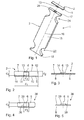
- Fig. 1 is an embodiment of a set 1 for making nail corrections comprising a strip-shaped and leaf-spring-like nail clip 2 and a Nagelspangenapplikator 3 for application of the nail clip 2 on a nail 4 of a toe or finger (see Fig. 11 to Fig. 13 ).
- the nail clip 2 is used for sticking to a nail to be treated 4 of a toe or a finger, while the nail clip applicator 3 is used to apply the nail clip 2 on the nail 4.
- the nail clip 2 comprises according to the Fig. 2 and Fig. 3 a leaf spring-like strip 5 made of elastic plastic with a central-transverse axis 6, which is transverse to the longitudinal extent of the strip 5, an upper side 7, a lower side 8, two longitudinal edges 9, 10 and two spaced to the central transverse axis 6 lying edge regions 11, 12.
- the leaf-spring-like strip 5 is with respect to a through the central-transverse axis 6 going Middle plane formed substantially symmetrical and has a clasp length d 1 and a clasp width d 2 .
- the nail clip 2 may have another dimension depending on the nail 4 to be corrected of a toe or a finger. This is especially true for their clasp length d 1 , which varies depending on the application.
- clasp length d 1 varies depending on the application.
- These different clasp lengths d 1 can z. B. in a set 1 with a variety of part but also different length nail clips 2 may be provided. In principle, however, other clasp lengths d 1 are possible.
- a releasable covering 13 is provided at least in regions, which contains a ferromagnetic material 14.
- the ferromagnetic material 14 is preferably iron, nickel or cobalt. The elements mentioned have particularly good ferromagnetic properties at room temperature.
- the pad 13 is thinly applied to the top 7 of the leaf spring-like strip 5 and extends in the central region of the strip 5 adjacent to the central transverse axis 6.
- the pad 13 is preferably such a thin layer applied to the top 7 of the leaf spring-like strip 5, that the Top 7 a substantially flat surface, without noticeable elevations forms.
- the pad 13 has a relation to the Clasp length d 1 shorter longitudinal extent d 3 on.
- the transverse extent d 4 of the lining 13 corresponds essentially to the clasp width d 2 ; at least the transverse extent d 4 preferably covers at least 3 ⁇ 4 of the clasp width d 2 . But it can also be equal to the clasp width d 2 .
- the coating 13 is formed as a lacquer to which the ferromagnetic material 14 is admixed. Due to its good adhesive properties, a nail varnish to which iron, nickel and / or cobalt-containing particles are admixed is particularly suitable. Trained as a varnish coating 13 is releasably applied to the leaf-spring-like strip 5 of the nail clip 2 and has a different color design to the leaf-spring-like strip 5. The different color design serves to clearly identify the covering 13 containing the ferromagnetic material 14, so that it can be easily identified by a user and the user recognizes where the nail clip applicator 3 is to be attached to the nail clip 2.
- the leaf-spring-like strip 5 of the nail clip 2 is formed of an intrinsically elastic plastic, preferably of a multilayer glass fiber reinforced thermosetting plastic, which in particular comprises three glass fiber layers.
- a plastic preserves, not least because of the three-layer glass fiber reinforcement, even if it is designed as a very thin strip, for a long time its own elasticity.
- PE polyethylene
- Adjacent to its two each extending approximately perpendicular to the central longitudinal axis 16 end faces 17, 18 of the base body 15 each have an application zone 21, 22.
- the application zones 21, 22 include not only designed as application surfaces end faces 17, 18 but also at least one In the preferred embodiment, each application zone 21, 22 exactly two part-circular recesses 23.
- the recesses 23 are in the application zones 21, 22 with respect to the central longitudinal -Axis 16 opposite each other on the longitudinal sides 19, 20 are provided.
- main body 15 is alternatively provided only with an application zone 21 which extends adjacent to the end face 17.
- application zone 21 which extends adjacent to the end face 17.
- the application zones 21, 22 are substantially identical in construction and in particular also symmetrical to a central-transverse axis 27 of the main body, which runs substantially perpendicular to the central longitudinal axis 16. Due to the substantially identical construction of the application zones 21 and 22 is in the Fig. 11 to Fig. 13 by way of example, only one section of the nail clasp applicator 3 comprising the application zone 21 is shown.
- the application surface lengths d 5 and d 6 of the application surfaces 17 and 18, respectively, which extend substantially parallel to the central transverse axis 27 are different from one another.
- the application surface length d 5 is 20 mm and is thus larger than the application surface d 6 , which has an extension of 18 mm.
- Other length combinations d 5 / d 6 are also possible in principle.
- the application surface width d 7 of the application surfaces 17, 18 in the preferred first embodiment is 3 mm in each case. Other application surface widths are also possible in principle.
- the application surfaces 17, 18 are adapted in their extension to the respective extensions d 1 , d 2 of the nail clip 2 to be applied.
- the application surface length d 5 , d 6 corresponds to the respective clasp length d 1
- a support member 28, 29 is provided for releasably holding the nail clip 2 to be applied.
- the support members 28, 29 are magnetically formed, preferably as permanent magnets. Iron, nickel, cobalt, neodymium and / or a ferrite are particularly suitable as material for the holding elements 28, 29 designed as permanent magnets. Likewise, compounds or alloys with one or more of these materials are possible.
- Each holding element 28, 29 extends substantially adjacent to the central longitudinal axis 16 on the application surfaces 17, 18.
- the longitudinal extent d 8 of the holding elements 28, 29 is significantly smaller than the application surface lengths d 5 , d 6 .
- the width d 9 of the support members 28, 29 is less than the application surface width d. 7
- the support members 28, 29 respectively in recesses 30, 31 of the application surfaces 17, 18 are arranged.
- the recesses 30, 31 extend within the base body 15 along the central longitudinal axis 16 of the application surfaces 17, 18 away in the direction of the central-transverse axis 27. They are arranged approximately centrally to the central longitudinal axis 16.
- the recesses 30, 31 are viewed rectangular in section and adapted to the dimensions of the support members 28, 29.
- the length and the width of the recesses 30, 31 corresponds essentially to the dimensions d 8 , d 9 of the support elements 28, 29.
- the depth t 1 of the recesses 30, 31 corresponds in the preferred embodiment, at least the height h 1 of the support members 28, 29.
- the support members 28, 29 are fixed either by positive engagement in the recess 30, 31, or alternatively by means of a adhesive bond.
- the support members 28, 29 are inserted completely into the recesses 30, 31 in the preferred embodiment.
- the recesses 30, 31 preferably have a depth t 1 , which corresponds to the height h 1 of the support members 28, 29.
- the application surfaces 17, 18 thus form a flat surface which can be brought into contact with the nail clip 2.
- the nail clip 2 By means of the nail clip 2, the nail 4 of a toe to be corrected, which is too curved especially in the region of its lateral outer edges and accordingly not only ugly to look at, but also pain-causing.
- 12 and 13 is the sequence of application of the nail clip 2 on the nail 4 with the aid of Nagelspangenapplikators 3 shown.
- the toe to be treated 32 and the neighboring toe 33 are shown in a front view.
- the Nagelspangenapplikator 3 comes before the actual in the 11, 12 and 13 Application process shown used. It can be used with advantage also for determining the required for the nail 4 to be treated clasp length d 1 . Since the application surface lengths d 5 , d 6 are equal to one of the available clasp lengths d 1 , the nail clasp applicator 3 can be used to size the nail 4 to be treated. On the basis of the application surface length d 5 or d 6 , which has the best match with the width of the nail 4 to be treated, the nail clip 2 most suitable in this case is selected. From the plurality of available nail clips 2, each with a different clasp length d 1 , that is selected which, for example, has a spacing of approximately 1 mm from the lateral nail wall.
- the nail clip 2 selected in this way is fixed on the application surface 17 or 18 of the nail clip applier 3 belonging to this clip length d 1 on account of magnetic attraction.
- the first application zone 21 is used.
- the covering 13 contains ferromagnetic material 14
- the nail clip 2 can be gripped in a particularly simple manner by the holding element 28 of the nail clip applicator 3 designed as a permanent magnet.
- the nail clip applicator 3 with its first application surface 17 is to be brought close to the covering 13 of the nail clip 2.
- the nail clip 2 is stored, for example, in a nail clip storage device, not shown, in which there are a variety of nail clips 2 with different sizes.
- the covering 13 rests on the recess 30, the covering 13 preferably being in contact with the retaining element 28 located in the recess 30.
- the nail clip 2 is achieved exclusively by the magnetic interaction between the magnetic support member 28 and the ferromagnetic material 14 having coating 13.
- the nail clip 2 is coated on the side facing away from the Nagelspangenapplikator 3 underside 8 with a quick adhesive.
- the adhesive can also be applied to the nail 4 to be treated.
- the Nagelspangenapplikator 3 with the Erten nail clip 2 as in Fig. 11 shown attached to a lateral outer edge of the nail 4 to be treated, wherein the edge portion 11 of the leaf spring-like strip 5 first comes into contact with the nail 4.
- the nail-clasp applicator 3 may under certain circumstances tilt very far in the direction of the adjacent toe 33.
- the recess 21 is provided on the longitudinal side 19 of the Nagelspangenapplikators 3, which faces the Nachbarzehe 33 in this situation.
- the recess 23 provides a free space for the Nachbarzehe 33 (see. Fig. 11 ).
- the edge region 11 of the nail clip 2 is pressed by means of the Nagelspangenapplikators 3 as long as the lateral outer edge of the nail 4 until the instant adhesive has set so far that the nail clip 2 is fixed there on the nail 4. This is followed by a first pivoting movement of the Nagelspangenapplikators 3 to the center of the nail 4, ie in the direction of the arrow 34 (see Fig. 11 ). Once in this center position, the nail clip 2 is again pressed by means of the nail clip applicator 3 in this position on the nail 4 until the adhesive force effect is also present here (see Fig. 12 ).
- the support member 28 formed as a permanent magnet should preferably be chosen so that the magnetic attraction between the pad 13 and the support member 28 is less than the adhesive force between the nail 4 and the bottom 8 of the leaf spring-like strip 5 of the nail clip. 2
- the set 1 with the nail clip 2 and the Nagelspangenapplikator 3 facilitates the application of the nail clip 2 on a nail 4 considerably. Due to the magnetic interaction between Nagelspangenapplikator 3 and nail clip 2 no retaining elements are necessary, which must be attached with laborious manual work on the nail clip 2 and the Nagelspangenapplikator 3, and hold the nail clip 2 on the Nagelspangenapplikator. The treating podiatrist does not even have to grasp the nail clip 2, since the nail clip 2 is gripped by the magnetic interaction with the nail clip applicator 3.
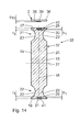
- Fig. 14 shows a second variant of a set 35 with a second embodiment of a nail clip 36 according to the Fig. 4, Fig. 5 , and a second embodiment of a Nagelspangenapplikator 37.
- Components that correspond to those described above with reference to the Fig. 1 to Fig. 13 have the same reference numbers and will not be discussed again in detail.
- the nail clip 36 differs from the nail clip 4 only by the design of the pad 38.
- the pad 38 which contains the ferromagnetic material 14 is formed as an adhesive strip and has a height d 10 on.
- the pad 38 according to Fig. 4, Fig. 5 and Fig. 14 preferably comprises a substantially rectangular body 39 made of ferromagnetic material, such as iron, nickel or cobalt.
- the pad 38 is glued in the second embodiment of the nail clip 36 on the leaf spring-like strip 5.
- the Nagelspangenapplikator 37 according to Fig. 14 differs from the Nagelspangenapplikator 3 by the arrangement of the support members 28, 29 in the recesses 30, 31.
- the in Fig. 14 illustrated insertion position of the support member 28, 29 is provided on the application surfaces 17, 18 each have a residual recess 40, 41.
- the residual recesses 40, 41 are generated in that the height h 1 of the support elements 28, 29 is less than the depth t 1 of the recesses 30, 31st
- the Restausnatural insects 40, 41 are used when applying the Nagelspange 36 using the Nagelspangenapplikators 37 for cooperation with the pad 38th
- the pad 38 engages in one of the Restausappelisme 40, 41, whereby the top 17 of the nail clip 36, which is not provided with the pad 38, flush on one of Application surfaces 17, 18 rests.
- the dimensions d 3 , d 4 of the pad 38 are chosen so that they are smaller than the dimensions of the Restausappelisme 40, 41.
- Fig. 15 shows a third variant of a Nagelspangenapplikators 42.
- Components that correspond to those already described above with reference to the Fig. 1 to Fig. 14 have the same reference numbers and will not be discussed again in detail.
- the Nagelspangenapplikator 42 has approximately the shape of a pencil and comprises a longitudinally extending elongated base body 43, the first end face 44 is round and is provided with an inwardly extending recess 45 into which a support member 46 is inserted.
- the support member 46 is used for releasably holding the nail clip 2 to be applied and is magnetically formed, preferably as a permanent magnet.
- As the material for the support member 46 formed as a permanent magnet iron, nickel, cobalt or ferrites are particularly suitable according to the support members 28, 29.
- the recess 45 preferably has a depth which is greater than a height of the support member 46, so that when inserted support member 46 at the application surface 44 a Restaus originallyung 48 is present, which can cooperate with a correspondingly shaped pad 38 of the nail clip 36.
- the second end face 47 of the Nagelspangenapplikators 42 is formed in the form of a small spatula and is suitable for applying the adhesive to the nail clip 2 or the nail 4.
Landscapes
- Health & Medical Sciences (AREA)
- Vascular Medicine (AREA)
- Animal Behavior & Ethology (AREA)
- Engineering & Computer Science (AREA)
- Biomedical Technology (AREA)
- Heart & Thoracic Surgery (AREA)
- Nursing (AREA)
- Life Sciences & Earth Sciences (AREA)
- Orthopedic Medicine & Surgery (AREA)
- General Health & Medical Sciences (AREA)
- Public Health (AREA)
- Veterinary Medicine (AREA)
- Orthopedics, Nursing, And Contraception (AREA)
- Cosmetics (AREA)
- Medicinal Preparation (AREA)
Abstract
Description
Der Inhalt der deutschen Patentanmeldung
Die Erfindung betrifft eine Nagelspange zur Vornahme von Nagelkorrekturen. Ferner richtet sich die Erfindung auf einen Nagelspangenapplikator zur Applikation der Nagelspange auf einen Nagel einer Zehe oder eines Fingers und auf ein Set zur Vornahme von Nagelkorrekturen, umfassend die Nagelspange und den Nagelspangenapplikator.The invention relates to a nail clip for making nail corrections. Further, the invention is directed to a Nagelspangenapplikator for application of the nail clip on a nail of a toe or a finger and on a set for making nail corrections, comprising the nail clip and the Nagelspangenapplikator.
Nagelspangen sind aus der
In der
In der
Es ist eine Aufgabe der vorliegenden Erfindung, sowohl einen Nagelspangenapplikator der eingangs bezeichneten Art als auch eine Nagelspange der eingangs bezeichneten Art bereitzustellen, mit denen die Applikation der Nagelspange auf den zu korrigierenden Nagel weiter vereinfacht wird. Der Erfindung liegt auch die Aufgabe zugrunde, ein Set zur Vornahme von Nagelkorrekturen mit einer entsprechenden Nagelspange und einem entsprechenden Nagelspangenapplikator zu schaffen.It is an object of the present invention to provide both a Nagelspangenapplikator of the type described as well as a nail clip of the type described, with which the application of the nail clip on the nail to be corrected is further simplified. The invention is also based on the object to provide a set for making nail corrections with a corresponding nail clip and a corresponding Nagelspangenapplikator.
Diese Aufgaben werden erfindungsgemäß durch die in den Ansprüchen 1, 9 und 14 angegebenen Merkmale gelöst. Der Kern der Erfindung liegt darin, dass die Nagelspange einen zumindest bereichsweise auf dem Streifen vorgesehenen Belag aufweist, der ein Magnetmaterial enthält, während der Nagelspangenapplikator ein magnetisches Halterungselement, insbesondere in Form eines Permanentmagneten, aufweist. Bei dem für den Belag des Streifens vorgesehenen Magnetmaterial kann es sich insbesondere um ein magnetisches oder magnetisierbares Material handeln.These objects are achieved by the features specified in
Erfindungsgemäß wurde erkannt, dass eine Nagelspange dann besonders einfach auf dem Nagelspangenapplikator zu befestigen ist, wenn die Nagelspange einen Belag aus Magnetmaterial enthält, der mit dem magnetischen Halterungselement des Nagelspangenapplikators wechselwirkt. Zusätzliche Befestigungselemente können dann entfallen.According to the invention it has been recognized that a nail clip is then particularly easy to attach to the Nagelspangenapplikator when the nail clip contains a coating of magnetic material that interacts with the magnetic support member of Nagelspangenapplikators. Additional fasteners can then be omitted.
Gemäß einer vorteilhaften Variante ist der Belag lösbar an dem blattfederartigen Streifen der Nagelspange vorgesehen. Dadurch wird erreicht, dass der Belag nach dem Aufbringen der Nagelspange auf dem zu behandelnden Nagel wieder von dem blattfederartigen Streifen der Nagelspange entfernbar ist. Die Nagelspange ist vorzugsweise transparent ausgebildet, und ist an dem Nagel nur durch nähere Betrachtung zu erkennen. Falls sich der das Magnetmaterial aufweisende Belag farblich von der Nagelspange abhebt, ist es aus ästhetischen Gründen zweckdienlich, den Belag nach der Applikation der Nagelspange wieder von der Nagelspange abzulösen.According to an advantageous variant, the covering is detachably provided on the leaf-spring-like strip of the nail clip. This ensures that the coating after application of the nail clip on the nail to be treated is again removed from the leaf spring-like strip of the nail clip. The nail clip is preferably transparent, and can be seen on the nail only by closer inspection. If the covering comprising the magnetic material stands out in color from the nail clip, it is expedient for aesthetic reasons to detach the covering again from the nail clip after application of the nail clip.
Gemäß der Ausgestaltung nach Anspruch 3 erstreckt sich der Belag benachbart zu einer Mittel-Quer-Achse des blattfederartigen Streifens. Durch diese Anordnung kann die Nagelspange durch den Nagelspangenapplikator mittig ergriffen werden, wodurch die Nagelspange zentriert mit einer Applikationsfläche des Nagelspangenapplikators in Kontakt bringbar ist.According to the embodiment of
Gemäß Anspruch 4 ist der Belag als Lack ausgebildet, dem das Magnetmaterial zugemischt ist. Es liegt dann also insbesondere ein (magnetischer) Metalllack vor. Bevorzugt kann es sich bei dem Lack auch um einen Nagellack handeln. Durch die Zumischung des Magnetmaterials zu einem Lack wird das Aufbringen des Belags auf den blattfederartigen Streifen der Nagelspange wesentlich erleichtert. Nagellack besteht im Wesentlichen aus Nitrozellulose, Lösungsmitteln und gegebenenfalls aus Farbpigmenten. Ein derartiger Nagellack weist ein hohes Haftvermögen und hohe Haltbarkeit auf. Er lässt sich einfach auf den blattfederartigen Streifen der Nagelspange auftragen. Außerdem ist er praktisch überall erhältlich und weist damit eine hohe Verfügbarkeit auf.According to
Gemäß einer weiteren günstigen Ausgestaltung nach Anspruch 5 ist der Belag als Klebestreifen ausgebildet, der das ferromagnetische Material umfasst und der auf den blattfederartigen Streifen geklebt ist. Durch diese Ausbildung des Belags als Klebestreifen kann auf zusätzliche Hilfsmittel zum Aufbringen des Belags auf die Nagelspange verzichtet werden. Der Klebestreifen kann beispielsweise per Hand auf die Nagelspange geklebt werden. Das Klebematerial kann dabei so gewählt werden, dass ein Wiederablösen des Klebestreifens von der Nagelspange nach dem Applizieren der Nagelspange auf den Nagel leicht möglich ist.According to a further advantageous embodiment according to
Dadurch, dass das Magnetmaterial gemäß einer weiteren günstigen Ausgestaltung ein ferromagnetisches Material und insbesondere mindestens ein Element der Gruppe aus Eisen, Nickel und Kobalt umfasst, wird gewährleistet, dass die Nagelspange durch einen Nagelspangenapplikator mit einem magnetischen Halterungselement leicht ergriffen werden kann. Mittels Eisen, Nickel und/oder Kobalt lassen sich unter Normalbedingungen hohe magnetische Haltekräfte erzielen.The fact that the magnetic material according to a further advantageous embodiment comprises a ferromagnetic material and in particular at least one element of the group consisting of iron, nickel and cobalt, ensures that the nail clip can be easily grasped by a Nagelspangenapplikator with a magnetic support member. By means of iron, nickel and / or cobalt, high magnetic holding forces can be achieved under normal conditions.
Eine weitere vorteilhafte Variante nach Anspruch 7 sieht vor, dass das Magnetmaterial partikelförmig, und insbesondere mit einer mittleren Partikelgröße im Bereich zwischen 5 µm und 100 µm, ausgebildet ist. Durch die partikelförmige Gestaltung des Magnetmaterials kann dieses auf einfache Art und Weise weitgehend beliebigen Substanzen zugemischt werden, die dann als Belag auf die Nagelspange aufbringbar sind. Es ist jedoch grundsätzlich auch möglich, das partikelförmige Magnetmaterial direkt auf der Nagelspange aufzubringen.A further advantageous variant according to
Gemäß der Ausgestaltung nach Anspruch 8 besteht der blattfederartige Streifen aus einem mehrlagigen glasfaserverstärkten Duroplast, der insbesondere drei Glasfaserlagen umfasst. Eine derartige Gestaltung ist besonders vorteilhaft, da zwischen Kunststoff und menschlichen Nägeln mittels Schnellkleber eine sehr schnell wirksame und außerordentlich haltbare Verbindung hergestellt werden kann. Durch das Vorsehen von drei Glasfaserlagen wird die Steifigkeit der Nagelspange gegenüber einer einlagigen Gestaltung erhöht. Dies bringt den Vorteil, dass die Rückstellkraft des blattfederartigen Streifens erhöht wird, wodurch die Wirkung der Nagelspange weiter verbessert ist.According to the embodiment of
Dadurch, dass gemäß Anspruch 10 das Halterungselement des Nagelspangenapplikators im Wesentlichen benachbart zu einer Mittel-Quer-Achse einer Applikationsfläche des Nagelspangenapplikators an der Applikationsfläche angeordnet ist, wird ermöglicht, dass die Nagelspange zentriert an der Applikationsfläche anlegbar ist. Insbesondere, wenn sich der das Magnetmaterial aufweisende Belag der Nagelspange benachbart zur Mittel-Quer-Achse der Nagelspange erstreckt und das magnetisch ausgebildete Halterungselement benachbart zur Mittel-Quer-Achse der Applikationsfläche des Nagelspangenapplikators, sind die Applikationsfläche und die Nagelspange benachbart zu einer gemeinsamen Mittel-Quer-Achse in Kontakt bringbar, wodurch eine stabile Auflage der Nagelspange an der Applikationsfläche ermöglicht wird.Characterized in that according to
Gemäß Anspruch 11 ist das Halterungselement des Nagelspangenapplikators in einer Ausnehmung der Applikationsfläche angeordnet. Durch diese Anordnung wird eine sichere Fixierung des Halterungselements an der Applikationsfläche erreicht.In accordance with
Durch die Anordnung nach Anspruch 12 wird ermöglicht, dass das Halterungselement nicht über die Applikationsfläche hinaus vorspringt und somit eine im Wesentlichen ebene Applikationsfläche bereitgestellt wird.The arrangement according to
Die Gestaltung nach Anspruch 13 schafft die Möglichkeit, dass der Belag der Nagelspange in eine erste Restausnehmung der Applikationsfläche eintauchen kann. Dadurch ergibt sich ein zusätzlicher Formschluss zwischen der Restausnehmung der Applikationsfläche und dem Belag der Nagelspange. Außerdem wird so auch bei einem Belag mit einer gewissen Belagdicke ein bündiges Aufliegen der Nagelspange auf der Applikationsfläche ermöglicht und die Nagelspange sicher an der ersten Applikationsfläche gehalten.The design according to
Nachfolgend werden unter Bezugnahme auf die beigefügte Zeichnung Ausführungsbeispiele der Erfindungsgegenstände beschrieben. Dabei zeigen:
- Fig. 1
- ein Ausführungsbeispiel eines Sets zur Vornahme von Nagelkorrekturen mit einer Nagelspange und einem Nagelspangenapplikator in einer perspektivischen Darstellung;
- Fig. 2
- ein Ausführungsbeispiel für die Nagelspange gemäß
Fig. 1 in einer Ansicht von unten; - Fig. 3
- eine Seitenansicht der Nagelspange gemäß
Fig. 2 ; - Fig. 4
- ein zweites Ausführungsbeispiel für die Nagelspange gemäß
Fig. 1 ; - Fig. 5
- eine Seitenansicht der Nagelspange nach
Fig. 4 ; - Fig. 6
- ein Ausführungsbeispiel für den Nagelspangenapplikators nach
Fig. 1 in einer Frontansicht; - Fig. 7
- eine Seitenansicht des Nagelspangenapplikators nach
Fig. 6 ; - Fig. 8
- eine Draufsicht auf den Nagelspangenapplikator gemäß
Fig. 6 ; - Fig. 9
- eine Schnittdarstellung des Nagelspangenapplikators entsprechend der Schnittlinie IX-IX in
Fig. 7 ; - Fig. 10
- eine Schnittdarstellung des Nagelspangenapplikators entsprechend der Schnittlinie IX-IX in
Fig. 7 mit einer an einer Applikationsfläche gehaltenen Nagelspange; - Fig. 11 bis Fig. 13
- den Ablauf einer Applikation einer Nagelspange auf einen Zehennagel unter Verwendung des Nagelspangenapplikators gemäß
Fig. 6 bis Fig. 9 ; - Fig. 14
- ein zweites Ausführungsbeispiel eines Sets mit einem zweiten Ausführungsbeispiel eines Nagelspangenapplikators mit der Nagelspange gemäß
Fig. 4 und Fig. 5 ; und - Fig. 15
- ein drittes Ausführungsbeispiel für einen Nagelspangenapplikator.
- Fig. 1
- an embodiment of a set for making nail corrections with a nail clip and a Nagelspangenapplikator in a perspective view;
- Fig. 2
- an embodiment of the nail clip according to
Fig. 1 in a view from below; - Fig. 3
- a side view of the nail clip according to
Fig. 2 ; - Fig. 4
- a second embodiment of the nail clip according to
Fig. 1 ; - Fig. 5
- a side view of the nail clip after
Fig. 4 ; - Fig. 6
- an embodiment of the Nagelspangenapplikators after
Fig. 1 in a front view; - Fig. 7
- a side view of the Nagelspangenapplikators after
Fig. 6 ; - Fig. 8
- a plan view of the Nagelspangenapplikator according to
Fig. 6 ; - Fig. 9
- a sectional view of the Nagelspangenapplikators corresponding to the section line IX-IX in
Fig. 7 ; - Fig. 10
- a sectional view of the Nagelspangenapplikators corresponding to the section line IX-IX in
Fig. 7 with a nail clip held on an application surface; - Fig. 11 to Fig. 13
- the sequence of application of a nail clip on a toenail using the Nagelspangenapplikators according to
FIG. 6 to FIG. 9 ; - Fig. 14
- a second embodiment of a set with a second embodiment of a Nagelspangenapplikators with the nail clip according to
4 and FIG. 5 ; and - Fig. 15
- a third embodiment of a Nagelspangenapplikator.
Einander entsprechende Teile sind in den
In
Die Nagelspange 2 gemäß der ersten Ausführungsvariante umfasst gemäß den
Die Nagelspange 2 kann je nach zu korrigierendem Nagel 4 einer Zehe oder eines Fingers eine andere Abmessung haben. Dies gilt insbesondere für ihre Spangenlänge d1, die je nach Anwendungsfall variiert. So gibt es Nagelspangen 2 mit einer Spangenlänge d1 von beispielsweise 30 mm, 24 mm, 22 mm, 20 mm, 18 mm, 16 mm und 14 mm. Diese verschiedenen Spangenlängen d1 können z. B. in einem Set 1 mit einer Vielzahl zum Teil aber auch unterschiedlich langer Nagelspangen 2 vorgesehen sein. Grundsätzlich sind aber auch andere Spangenlängen d1 möglich.The
Auf der Oberseite 7 des blattfederartigen Streifens 5 ist zumindest bereichsweise ein lösbarer Belag 13 vorgesehen, der ein ferromagnetisches Material 14 enthält. Bei dem ferromagnetischen Material 14 handelt es sich vorzugsweise um Eisen, Nickel oder Kobalt. Die genannten Elemente weisen bei Raumtemperatur besonders gute ferromagnetische Eigenschaften auf.On the
Der Belag 13 ist dünnschichtig auf die Oberseite 7 des blattfederartigen Streifens 5 aufgetragen und erstreckt sich im Mittelbereich des Streifens 5 benachbart zur Mittel-Quer-Achse 6. Der Belag 13 ist vorzugsweise derartig dünnschichtig auf die Oberseite 7 des blattfederartigen Streifens 5 aufgetragen, dass die Oberseite 7 eine im Wesentlichen ebene Fläche, ohne merkliche Erhebungen bildet. Der Belag 13 weist eine im Verhältnis zu der Spangenlänge d1 kürzere Längserstreckung d3 auf. Die Quererstreckung d4 des Belages 13 entspricht in der bevorzugten Ausführungsvariante im Wesentlichen der Spangenbreite d2, zumindest deckt die Quererstreckung d4 vorzugsweise zumindest ¾ der Spangenbreite d2 ab. Sie kann aber auch gleich der Spangenbreite d2 sein.The
In einer bevorzugten Ausführungsform ist der Belag 13 als Lack ausgebildet, dem das ferromagnetische Material 14 zugemischt ist. Besonders gut eignet sich aufgrund seiner guten Hafteigenschaften ein Nagellack, dem Eisen, Nickel und/oder Kobalt enthaltende Partikel zugemischt werden. Der als Lack ausgebildete Belag 13 ist dabei lösbar auf dem blattfederartigen Streifen 5 der Nagelspange 2 aufgebracht und weist eine zum blattfederartigen Streifen 5 verschiedene farbliche Gestaltung auf. Die unterschiedliche Farbgestaltung dient dazu, den das ferromagnetische Material 14 enthaltenden Belag 13 deutlich zu kennzeichnen, damit dieser durch einen Anwender einfach identifizierbar ist und der Anwender erkennt, wo an der Nagelspange 2 der Nagelspangenapplikator 3 anzusetzen ist.In a preferred embodiment, the
Der blattfederartige Streifen 5 der Nagelspange 2 ist aus einem eigenelastischen Kunststoff ausgebildet, vorzugsweise aus einem mehrlagigen glasfaserverstärkten Duroplast, der insbesondere drei Glasfaserlagen umfasst. Ein solcher Kunststoff bewahrt, nicht zuletzt aufgrund der dreilagigen Glasfaserverstärkung, selbst dann, wenn er als sehr dünner Streifen ausgebildet ist, über lange Zeit seine Eigenelastizität. Die durch die drei Glasfaserlagen erreichte hohe Rückstellwirkung, welche auf den Nagel 4 durch eine auf diesen angebrachte Nagelspange 2 ausgeübt wird, lässt folglich nicht kurz nach der Fixierung der Nagelspange 2 schon wieder nach.The leaf-spring-
Die Applikation der Nagelspange 2 auf den Nagel 4 erfolgt unter Zuhilfenahme des Nagelspangenapplikators 3.The application of the
Der Nagelspangenapplikator 3 umfasst einen länglichen Grundkörper 15 aus Polyethylen (PE) mit einer quaderförmigen Grundform, dessen größte geometrische Abmessung (= Länge) sich entlang einer Mittel-Längs-Achse 16 erstreckt, zwei als Applikationsflächen ausgebildete Stirnseiten 17, 18 und zwei im wesentlichen parallel zur Mittel-Längs-Achse 16 verlaufende Längsseiten 19, 20.The
Angrenzend an seine beiden jeweils in etwa senkrecht zur Mittel-Längs-Achse 16 verlaufenden Stirnseiten 17, 18 hat der Grundkörper 15 jeweils eine Applikationszone 21, 22. Die Applikationszonen 21, 22 umfassen neben den als Applikationsflächen ausgebildeten Stirnseiten 17, 18 auch jeweils mindestens eine gebogene, im Ausführungsbeispiel teilkreisförmige, Ausnehmung 23 an den Längsseiten 19, 20 des Grundkörpers 15. In der bevorzugten Ausführungsvariante umfasst jede Applikationszone 21, 22 genau zwei teilkreisförmige Ausnehmungen 23. Die Ausnehmungen 23 sind dabei in den Applikationszonen 21, 22 bezüglich der Mittel-Längs-Achse 16 einander gegenüberliegend an den Längsseiten 19, 20 vorgesehen.Adjacent to its two each extending approximately perpendicular to the central
Es grundsätzlich auch vorstellbar, dass der Grundkörper 15 alternativ nur mit einer Applikationszone 21 versehen ist, die sich benachbart zur Stirnseite 17 erstreckt. Der Bereich des Grundkörpers 15, der benachbart zur Stirnseite 18 ist, ist in diesem Fall ohne Ausnehmungen an den Längsseiten 19, 20 zu gestalten.It is basically also conceivable that the
Abgesehen von der Ausdehnung der Applikationsflächen 17, 18 sind die Applikationszonen 21, 22 im Wesentlichen baugleich und insbesondere auch symmetrisch zu einer Mittel-Quer-Achse 27 des Grundkörpers, die im Wesentlichen senkrecht zur Mittel-Längs-Achse 16 verläuft, ausgeführt. Aufgrund der im Wesentlichen gegebenen Baugleichheit der Applikationszonen 21 und 22 ist in den
Die Applikationsflächenlängen d5 bzw. d6 der Applikationsflächen 17 bzw.18, die sich im Wesentlichen parallel zu der Mittel-Quer-Achse 27 erstrecken, sind voneinander verschieden. Die Applikationsflächenlängen d5 bzw. d6 entsprechen jeweils einer Breite des Grundkörper 15 im Bereich der jeweiligen Stirnseiten (= Applikationsflächen 17 bzw. 18). Im Ausführungsbeispiel beträgt die Applikationsflächenlänge d5 20 mm und ist damit größer als die Applikationsfläche d6, die eine Ausdehnung von 18 mm aufweist. Andere Längenkombinationen d5/d6 sind grundsätzlich ebenfalls möglich. Die Applikationsflächenbreite d7 der Applikationsflächen 17, 18 beträgt in der bevorzugten ersten Ausführungsvariante jeweils 3 mm. Andere Applikationsflächenbreiten sind grundsätzlich ebenfalls möglich.The application surface lengths d 5 and d 6 of the application surfaces 17 and 18, respectively, which extend substantially parallel to the central
Die Applikationsflächen 17, 18 sind in ihrer Ausdehnung an die jeweiligen Ausdehnungen d1, d2 der zu applizierenden Nagelspange 2 angepasst. Vorzugsweise entspricht die Applikationsflächenlänge d5, d6 der jeweiligen Spangenlänge d1, und die Applikationsflächenbreite d7 der jeweiligen Spangenbreite d2 der zu applizierenden Nagelspange 2.The application surfaces 17, 18 are adapted in their extension to the respective extensions d 1 , d 2 of the
An den Applikationsflächen 17, 18 ist jeweils ein Halterungselement 28, 29 zur lösbaren Halterung der zu applizierenden Nagelspange 2 vorgesehen. Die Halterungselemente 28, 29 sind dabei magnetisch ausgebildet, vorzugsweise als Permanentmagnete. Als Material für die als Permanentmagnete ausgebildeten Halterungselemente 28, 29 eignet sich insbesondere Eisen, Nickel, Kobalt, Neodym und/oder ein Ferrit. Ebenso sind Verbindungen oder Legierungen mit einem oder mehreren dieser Materialien möglich.At the application surfaces 17, 18 is in each case a
Es ist grundsätzlich auch vorstellbar, dass alternativ nur eine der Applikationsflächen 17 oder 18 mit einem Halterungselement 28 oder 29 versehen ist. Diese Anordnung ist dann zu wählen, wenn an dem Grundkörper 15 nur eine Applikationszone 21 oder 22 vorgesehen ist.In principle, it is also conceivable that alternatively only one of the application surfaces 17 or 18 is provided with a holding
Jedes Halterungselement 28, 29 erstreckt sich im Wesentlichen benachbart zu der Mittel-Längs-Achse 16 an den Applikationsflächen 17, 18. Die Längserstreckungen d8 der Halterungselemente 28, 29 ist dabei deutlich geringer als die Applikationsflächenlängen d5, d6. Wie
In der bevorzugten Ausführungsvariante des Nagelspangenapplikators 3 gemäß den
Wie
Im Folgenden werden die Verwendung sowie besondere Eigenschaften und Vorteile des Nagelspangenapplikators 3 zur Applikation der Nagelspange 2 auf den Nagel 4 einer Zehe näher beschrieben, wobei insbesondere auf die Darstellungen gemäß
Mittels der Nagelspange 2 soll der Nagel 4 einer Zehe korrigiert werden, der insbesondere im Bereich seiner seitlichen Außenränder zu stark gekrümmt ist und dementsprechend nicht nur unschön anzusehen, sondern auch schmerzverursachend ist.By means of the
In
Der Nagelspangenapplikator 3 kommt bereits vor dem eigentlichen in den
Die so ausgewählte Nagelspange 2 wird aufgrund magnetischer Anziehung an der Applikationsfläche 17 oder 18 des zu dieser Spangenlänge d1 gehörigen Nagelspangenapplikators 3 fixiert. In den
Dadurch, dass der Belag 13 benachbart zu der Mittel-Quer-Achse 6 der Nagelspange 2, und das magnetische Halterungselement 28 benachbart zur Mittel-Längs-Achse 16 des Nagelspangenapplikators 3 vorgesehen ist, spannen in der in den
In der Auflage-Position der Nagelspange 2 auf der ersten Applikationsfläche 17 des Nagelspangenapplikators 3 liegt der Belag 13 auf der Ausnehmung 30 auf, wobei der Belag 13 vorzugsweise in Kontakt mit dem sich in der Ausnehmung 30 befindlichen Halterungselement 28 steht. Der Bereich der Oberseite 7 der Nagelspange 2, der nicht mit dem Belag 13 versehen ist, liegt in der Auflage-Position bündig auf der ersten Applikationsfläche 17 auf.In the resting position of the
Weitere Mittel zur Fixierung der Nagelspange 2 an dem Nagelspangenapplikator 3 sind nicht notwendig. Die Nagelspange 2 wird ausschließlich durch die magnetische Wechselwirkung zwischen dem magnetischen Halterungselement 28 und dem das ferromagnetische Material 14 aufweisenden Belag 13 erreicht.Further means for fixing the
Ausgehend von der in den
Der Randbereich 11 der Nagelspange 2 wird mittels des Nagelspangenapplikators 3 solange an dem seitlichen Außenrand des Nagels 4 gedrückt, bis der Schnellkleber soweit abgebunden hat, dass die Nagelspange 2 dort an dem Nagel 4 fixiert ist. Es folgt eine erste Schwenkbewegung des Nagelspangenapplikators 3 zur Mitte des Nagels 4, also in Richtung des Pfeils 34 (siehe
Das als Permanentmagnet ausgebildete Halterungselement 28 sollte vorzugsweise so gewählt werden, dass die magnetische Anziehung zwischen dem Belag 13 und dem Halterungselement 28 geringer ist als die Klebekraft zwischen dem Nagel 4 und der Unterseite 8 des blattfederartigen Streifens 5 der Nagelspange 2.The
Die Schwenkbewegung in Richtung des Pfeils 34 des Nagelspangenapplikators 3 wird bis zum bislang noch nicht erfaßten seitlichen Außenrand des Nagels 4 fortgesetzt (siehe
Das Set 1 mit der Nagelspange 2 und dem Nagelspangenapplikator 3 erleichtert die Applikation der Nagelspange 2 auf einem Nagel 4 erheblich. Durch die magnetische Wechselwirkung zwischen Nagelspangenapplikator 3 und Nagelspange 2 sind keine Halteelemente notwendig, die mit mühseliger Handarbeit an der Nagelspange 2 und dem Nagelspangenapplikator 3 angebracht werden müssen, und die die Nagelspange 2 an dem Nagelspangenapplikator halten. Der behandelnde Fußpfleger muss die Nagelspange 2 nicht einmal selbst greifen, da die Nagelspange 2 durch die magnetische Wechselwirkung mit dem Nagelspangenapplikator 3 ergriffen wird.The
Die Nagelspange 36 unterscheidet sich von der Nagelspange 4 nur durch die Ausgestaltung des Belags 38. Der Belag 38, der das ferromagnetische Material 14 enthält ist als Klebestreifen ausgebildet und weist eine Höhe d10 auf. Der Belag 38 gemäß
Der Nagelspangenapplikator 37 gemäß
Die Restausnehmungen 40, 41 dienen beim Applizieren der Nagelspange 36 mit Hilfe des Nagelspangenapplikators 37 zum Zusammenwirken mit dem Belag 38.The
In der Auflage-Position der Nagelspange 36 auf der ersten Applikationsfläche 17 des Nagelspangenapplikators 37 greift der Belag 38 in einer der Restausnehmungen 40, 41 ein, wodurch die Oberseite 17 der Nagelspange 36, die nicht mit dem Belag 38 versehen ist, bündig auf einer der Applikationsflächen 17, 18 aufliegt. Die Abmessungen d3, d4 des Belags 38 sind so gewählt, dass diese geringer sind als die Dimensionierung der Restausnehmungen 40, 41. Durch diese Ausgestaltung taucht der Belag 38 in der Auflage-Position mit seiner ganzen Höhe d10 in eine der Restausnehmungen 30, 31 ein. Durch das Ineinandergreifen des Belages 38 mit einer der Ausnehmungen 30, 31 wird die Nagelspange 36 zusätzlich an dem Nagelspangenapplikator 37 fixiert und gegen ein Verrutschen an den Applikationsflächen 17, 18 gesichert.In the resting position of the
Der Nagelspangenapplikator 42 gemäß
Die zweite Stirnseite 47 des Nagelspangenapplikators 42 ist in Form eines kleinen Spatels ausgebildet und ist zum Auftragen des Klebstoffs auf die Nagelspange 2 oder den Nagel 4 geeignet.The
Claims (14)
Priority Applications (1)
| Application Number | Priority Date | Filing Date | Title |
|---|---|---|---|
| PL12190646T PL2596772T3 (en) | 2011-11-25 | 2012-10-30 | Nail brace, nail brace applicator and application set |
Applications Claiming Priority (1)
| Application Number | Priority Date | Filing Date | Title |
|---|---|---|---|
| DE102011087144A DE102011087144B4 (en) | 2011-11-25 | 2011-11-25 | Nail clip, nail clip applicator and application set |
Publications (2)
| Publication Number | Publication Date |
|---|---|
| EP2596772A1 true EP2596772A1 (en) | 2013-05-29 |
| EP2596772B1 EP2596772B1 (en) | 2014-05-21 |
Family
ID=47143627
Family Applications (1)
| Application Number | Title | Priority Date | Filing Date |
|---|---|---|---|
| EP12190646.5A Active EP2596772B1 (en) | 2011-11-25 | 2012-10-30 | Nail brace, nail brace applicator and application set |
Country Status (7)
| Country | Link |
|---|---|
| EP (1) | EP2596772B1 (en) |
| JP (1) | JP5744820B2 (en) |
| KR (1) | KR101487581B1 (en) |
| CN (1) | CN103126795B (en) |
| DE (1) | DE102011087144B4 (en) |
| ES (1) | ES2491817T3 (en) |
| PL (1) | PL2596772T3 (en) |
Families Citing this family (3)
| Publication number | Priority date | Publication date | Assignee | Title |
|---|---|---|---|---|
| JP2015164833A (en) * | 2014-02-05 | 2015-09-17 | 株式会社マルイ | Bicycle saddle and manufacturing method thereof |
| KR200493704Y1 (en) | 2021-02-23 | 2021-05-24 | 주식회사 킹케어 | Correcting Strip for Ingrown nail |
| KR102379870B1 (en) | 2021-11-01 | 2022-03-30 | 주식회사 킹케어 | Correcting Strip for Ingrown nail |
Citations (4)
| Publication number | Priority date | Publication date | Assignee | Title |
|---|---|---|---|---|
| US4057055A (en) * | 1975-08-22 | 1977-11-08 | Clark John H | Toenail appliance and method |
| EP0282645B1 (en) | 1987-03-18 | 1990-05-30 | Bernd Stolz | Device for correcting nails |
| US20090048551A1 (en) | 2006-03-09 | 2009-02-19 | Aharon Liberson | Device and method for treating ingrown nails |
| DE102008010442B3 (en) | 2008-02-21 | 2009-07-30 | Bernd Stolz | Nagelspangenapplikator |
Family Cites Families (5)
| Publication number | Priority date | Publication date | Assignee | Title |
|---|---|---|---|---|
| JPH0626287Y2 (en) * | 1992-04-06 | 1994-07-20 | 秀夫 矢野 | Magnetic therapeutic patch application device |
| JP3474998B2 (en) * | 1996-03-21 | 2003-12-08 | 古河電気工業株式会社 | Ingrown nail correction tool |
| JP3519858B2 (en) * | 1996-03-21 | 2004-04-19 | 古河電気工業株式会社 | Ingrown nail correction tool |
| KR200335630Y1 (en) | 2003-07-21 | 2003-12-11 | 주식회사 에프에스코리아 | Emery board for trimming a nail which has a magnet therein |
| CN101437474B (en) * | 2006-05-08 | 2011-11-30 | 植村富美子 | Nail shaper for ingrown nail and false nail |
-
2011
- 2011-11-25 DE DE102011087144A patent/DE102011087144B4/en not_active Expired - Fee Related
-
2012
- 2012-10-30 ES ES12190646.5T patent/ES2491817T3/en active Active
- 2012-10-30 PL PL12190646T patent/PL2596772T3/en unknown
- 2012-10-30 EP EP12190646.5A patent/EP2596772B1/en active Active
- 2012-11-12 JP JP2012248282A patent/JP5744820B2/en active Active
- 2012-11-23 CN CN201210482798.9A patent/CN103126795B/en active Active
- 2012-11-23 KR KR20120133753A patent/KR101487581B1/en active IP Right Grant
Patent Citations (4)
| Publication number | Priority date | Publication date | Assignee | Title |
|---|---|---|---|---|
| US4057055A (en) * | 1975-08-22 | 1977-11-08 | Clark John H | Toenail appliance and method |
| EP0282645B1 (en) | 1987-03-18 | 1990-05-30 | Bernd Stolz | Device for correcting nails |
| US20090048551A1 (en) | 2006-03-09 | 2009-02-19 | Aharon Liberson | Device and method for treating ingrown nails |
| DE102008010442B3 (en) | 2008-02-21 | 2009-07-30 | Bernd Stolz | Nagelspangenapplikator |
Also Published As
| Publication number | Publication date |
|---|---|
| PL2596772T3 (en) | 2014-10-31 |
| EP2596772B1 (en) | 2014-05-21 |
| KR101487581B1 (en) | 2015-01-29 |
| ES2491817T3 (en) | 2014-09-08 |
| DE102011087144B4 (en) | 2013-09-19 |
| KR20130058634A (en) | 2013-06-04 |
| JP2013111477A (en) | 2013-06-10 |
| CN103126795A (en) | 2013-06-05 |
| CN103126795B (en) | 2016-01-20 |
| JP5744820B2 (en) | 2015-07-08 |
| DE102011087144A1 (en) | 2013-05-29 |
Similar Documents
| Publication | Publication Date | Title |
|---|---|---|
| DE2831436C3 (en) | License plate carrier | |
| EP1481620B1 (en) | Container with a device for indicating the filling quantity | |
| DE102010030813A1 (en) | Apparatus for applying a magnetic particle-containing cosmetic product and device-containing unit | |
| EP2596772B1 (en) | Nail brace, nail brace applicator and application set | |
| DE2428782A1 (en) | SELF-ADHESIVE CLOSURE | |
| EP3337359A1 (en) | Retaining body, retaining device and method for installing a retaining device | |
| EP0282645B1 (en) | Device for correcting nails | |
| DE202009016050U1 (en) | Were Divider | |
| DE202006005621U1 (en) | Locking device e.g. frustum-shaped plug, for concrete wall, has metal disc with optical attractive visible surface superimposed on front surface, where diameter of disc is larger than largest diameter of block out | |
| DE102008010442B3 (en) | Nagelspangenapplikator | |
| DE202017105482U1 (en) | Holding device for cards and / or bills | |
| DE102015100323B4 (en) | Device for nail correction | |
| EP0388650A1 (en) | Traffic surface-marking element | |
| DE8503947U1 (en) | Tool for forming joints from permanently elastic silicone jointing compound or the like. | |
| DE10148937A1 (en) | Cover profile for conductors especially cable bridges, has heavy edge material of low elasticity along long side | |
| DE102017104744A1 (en) | Universal slider for floor cleaning | |
| DE202008014451U1 (en) | Device for applying a liquid, gelatinous, pasty or powdery product | |
| DE3309925A1 (en) | PLASTIC HAIR COMB | |
| DE10164742B4 (en) | Product for attaching cannulas, tubes or electrodes | |
| DE102009052635B4 (en) | Double-sided adhesive pad | |
| EP0638441B1 (en) | Device for detachable adhering business cards with file cards | |
| DE102014109467A1 (en) | Holding part, planar protective device and method for the production of holding part and protective device | |
| DE102007030617A1 (en) | Corner connector for door and window frames | |
| DE4439878C2 (en) | Spacers that can be attached to a concrete reinforcing bar | |
| DE8415422U1 (en) | CLAMP HOLDER FOR NAILS, SCREWS OD. DGL. FASTENERS |
Legal Events
| Date | Code | Title | Description |
|---|---|---|---|
| PUAI | Public reference made under article 153(3) epc to a published international application that has entered the european phase |
Free format text: ORIGINAL CODE: 0009012 |
|
| AK | Designated contracting states |
Kind code of ref document: A1 Designated state(s): AL AT BE BG CH CY CZ DE DK EE ES FI FR GB GR HR HU IE IS IT LI LT LU LV MC MK MT NL NO PL PT RO RS SE SI SK SM TR |
|
| AX | Request for extension of the european patent |
Extension state: BA ME |
|
| 17P | Request for examination filed |
Effective date: 20130605 |
|
| RBV | Designated contracting states (corrected) |
Designated state(s): AL AT BE BG CH CY CZ DE DK EE ES FI FR GB GR HR HU IE IS IT LI LT LU LV MC MK MT NL NO PL PT RO RS SE SI SK SM TR |
|
| GRAP | Despatch of communication of intention to grant a patent |
Free format text: ORIGINAL CODE: EPIDOSNIGR1 |
|
| RIC1 | Information provided on ipc code assigned before grant |
Ipc: A61F 5/11 20060101AFI20131212BHEP |
|
| INTG | Intention to grant announced |
Effective date: 20140116 |
|
| GRAS | Grant fee paid |
Free format text: ORIGINAL CODE: EPIDOSNIGR3 |
|
| GRAA | (expected) grant |
Free format text: ORIGINAL CODE: 0009210 |
|
| AK | Designated contracting states |
Kind code of ref document: B1 Designated state(s): AL AT BE BG CH CY CZ DE DK EE ES FI FR GB GR HR HU IE IS IT LI LT LU LV MC MK MT NL NO PL PT RO RS SE SI SK SM TR |
|
| REG | Reference to a national code |
Ref country code: GB Ref legal event code: FG4D Free format text: NOT ENGLISH |
|
| REG | Reference to a national code |
Ref country code: CH Ref legal event code: EP |
|
| REG | Reference to a national code |
Ref country code: AT Ref legal event code: REF Ref document number: 669207 Country of ref document: AT Kind code of ref document: T Effective date: 20140615 |
|
| REG | Reference to a national code |
Ref country code: IE Ref legal event code: FG4D Free format text: LANGUAGE OF EP DOCUMENT: GERMAN |
|
| REG | Reference to a national code |
Ref country code: DE Ref legal event code: R096 Ref document number: 502012000775 Country of ref document: DE Effective date: 20140703 |
|
| REG | Reference to a national code |
Ref country code: NL Ref legal event code: T3 |
|
| REG | Reference to a national code |
Ref country code: ES Ref legal event code: FG2A Ref document number: 2491817 Country of ref document: ES Kind code of ref document: T3 Effective date: 20140908 |
|
| REG | Reference to a national code |
Ref country code: NO Ref legal event code: T2 Effective date: 20140521 |
|
| REG | Reference to a national code |
Ref country code: LT Ref legal event code: MG4D |
|
| PG25 | Lapsed in a contracting state [announced via postgrant information from national office to epo] |
Ref country code: GR Free format text: LAPSE BECAUSE OF FAILURE TO SUBMIT A TRANSLATION OF THE DESCRIPTION OR TO PAY THE FEE WITHIN THE PRESCRIBED TIME-LIMIT Effective date: 20140822 Ref country code: IS Free format text: LAPSE BECAUSE OF FAILURE TO SUBMIT A TRANSLATION OF THE DESCRIPTION OR TO PAY THE FEE WITHIN THE PRESCRIBED TIME-LIMIT Effective date: 20140921 Ref country code: LT Free format text: LAPSE BECAUSE OF FAILURE TO SUBMIT A TRANSLATION OF THE DESCRIPTION OR TO PAY THE FEE WITHIN THE PRESCRIBED TIME-LIMIT Effective date: 20140521 Ref country code: FI Free format text: LAPSE BECAUSE OF FAILURE TO SUBMIT A TRANSLATION OF THE DESCRIPTION OR TO PAY THE FEE WITHIN THE PRESCRIBED TIME-LIMIT Effective date: 20140521 |
|
| REG | Reference to a national code |
Ref country code: PL Ref legal event code: T3 |
|
| PG25 | Lapsed in a contracting state [announced via postgrant information from national office to epo] |
Ref country code: HR Free format text: LAPSE BECAUSE OF FAILURE TO SUBMIT A TRANSLATION OF THE DESCRIPTION OR TO PAY THE FEE WITHIN THE PRESCRIBED TIME-LIMIT Effective date: 20140521 Ref country code: LV Free format text: LAPSE BECAUSE OF FAILURE TO SUBMIT A TRANSLATION OF THE DESCRIPTION OR TO PAY THE FEE WITHIN THE PRESCRIBED TIME-LIMIT Effective date: 20140521 Ref country code: SE Free format text: LAPSE BECAUSE OF FAILURE TO SUBMIT A TRANSLATION OF THE DESCRIPTION OR TO PAY THE FEE WITHIN THE PRESCRIBED TIME-LIMIT Effective date: 20140521 Ref country code: RS Free format text: LAPSE BECAUSE OF FAILURE TO SUBMIT A TRANSLATION OF THE DESCRIPTION OR TO PAY THE FEE WITHIN THE PRESCRIBED TIME-LIMIT Effective date: 20140521 |
|
| PG25 | Lapsed in a contracting state [announced via postgrant information from national office to epo] |
Ref country code: PT Free format text: LAPSE BECAUSE OF FAILURE TO SUBMIT A TRANSLATION OF THE DESCRIPTION OR TO PAY THE FEE WITHIN THE PRESCRIBED TIME-LIMIT Effective date: 20140922 |
|
| PG25 | Lapsed in a contracting state [announced via postgrant information from national office to epo] |
Ref country code: RO Free format text: LAPSE BECAUSE OF FAILURE TO SUBMIT A TRANSLATION OF THE DESCRIPTION OR TO PAY THE FEE WITHIN THE PRESCRIBED TIME-LIMIT Effective date: 20140521 Ref country code: DK Free format text: LAPSE BECAUSE OF FAILURE TO SUBMIT A TRANSLATION OF THE DESCRIPTION OR TO PAY THE FEE WITHIN THE PRESCRIBED TIME-LIMIT Effective date: 20140521 Ref country code: EE Free format text: LAPSE BECAUSE OF FAILURE TO SUBMIT A TRANSLATION OF THE DESCRIPTION OR TO PAY THE FEE WITHIN THE PRESCRIBED TIME-LIMIT Effective date: 20140521 Ref country code: SK Free format text: LAPSE BECAUSE OF FAILURE TO SUBMIT A TRANSLATION OF THE DESCRIPTION OR TO PAY THE FEE WITHIN THE PRESCRIBED TIME-LIMIT Effective date: 20140521 Ref country code: CZ Free format text: LAPSE BECAUSE OF FAILURE TO SUBMIT A TRANSLATION OF THE DESCRIPTION OR TO PAY THE FEE WITHIN THE PRESCRIBED TIME-LIMIT Effective date: 20140521 |
|
| REG | Reference to a national code |
Ref country code: DE Ref legal event code: R097 Ref document number: 502012000775 Country of ref document: DE |
|
| PLBE | No opposition filed within time limit |
Free format text: ORIGINAL CODE: 0009261 |
|
| STAA | Information on the status of an ep patent application or granted ep patent |
Free format text: STATUS: NO OPPOSITION FILED WITHIN TIME LIMIT |
|
| 26N | No opposition filed |
Effective date: 20150224 |
|
| PG25 | Lapsed in a contracting state [announced via postgrant information from national office to epo] |
Ref country code: MC Free format text: LAPSE BECAUSE OF FAILURE TO SUBMIT A TRANSLATION OF THE DESCRIPTION OR TO PAY THE FEE WITHIN THE PRESCRIBED TIME-LIMIT Effective date: 20140521 Ref country code: LU Free format text: LAPSE BECAUSE OF FAILURE TO SUBMIT A TRANSLATION OF THE DESCRIPTION OR TO PAY THE FEE WITHIN THE PRESCRIBED TIME-LIMIT Effective date: 20141030 |
|
| REG | Reference to a national code |
Ref country code: DE Ref legal event code: R097 Ref document number: 502012000775 Country of ref document: DE Effective date: 20150224 |
|
| PG25 | Lapsed in a contracting state [announced via postgrant information from national office to epo] |
Ref country code: BE Free format text: LAPSE BECAUSE OF NON-PAYMENT OF DUE FEES Effective date: 20141031 |
|
| REG | Reference to a national code |
Ref country code: IE Ref legal event code: MM4A |
|
| PG25 | Lapsed in a contracting state [announced via postgrant information from national office to epo] |
Ref country code: SI Free format text: LAPSE BECAUSE OF FAILURE TO SUBMIT A TRANSLATION OF THE DESCRIPTION OR TO PAY THE FEE WITHIN THE PRESCRIBED TIME-LIMIT Effective date: 20140521 |
|
| REG | Reference to a national code |
Ref country code: PL Ref legal event code: RECP |
|
| REG | Reference to a national code |
Ref country code: FR Ref legal event code: PLFP Year of fee payment: 4 |
|
| PG25 | Lapsed in a contracting state [announced via postgrant information from national office to epo] |
Ref country code: IE Free format text: LAPSE BECAUSE OF NON-PAYMENT OF DUE FEES Effective date: 20141030 |
|
| PG25 | Lapsed in a contracting state [announced via postgrant information from national office to epo] |
Ref country code: CY Free format text: LAPSE BECAUSE OF FAILURE TO SUBMIT A TRANSLATION OF THE DESCRIPTION OR TO PAY THE FEE WITHIN THE PRESCRIBED TIME-LIMIT Effective date: 20140521 Ref country code: BG Free format text: LAPSE BECAUSE OF FAILURE TO SUBMIT A TRANSLATION OF THE DESCRIPTION OR TO PAY THE FEE WITHIN THE PRESCRIBED TIME-LIMIT Effective date: 20140521 |
|
| PG25 | Lapsed in a contracting state [announced via postgrant information from national office to epo] |
Ref country code: HU Free format text: LAPSE BECAUSE OF FAILURE TO SUBMIT A TRANSLATION OF THE DESCRIPTION OR TO PAY THE FEE WITHIN THE PRESCRIBED TIME-LIMIT; INVALID AB INITIO Effective date: 20121030 Ref country code: MT Free format text: LAPSE BECAUSE OF FAILURE TO SUBMIT A TRANSLATION OF THE DESCRIPTION OR TO PAY THE FEE WITHIN THE PRESCRIBED TIME-LIMIT Effective date: 20140521 |
|
| REG | Reference to a national code |
Ref country code: FR Ref legal event code: PLFP Year of fee payment: 5 |
|
| PG25 | Lapsed in a contracting state [announced via postgrant information from national office to epo] |
Ref country code: SM Free format text: LAPSE BECAUSE OF FAILURE TO SUBMIT A TRANSLATION OF THE DESCRIPTION OR TO PAY THE FEE WITHIN THE PRESCRIBED TIME-LIMIT Effective date: 20140521 |
|
| REG | Reference to a national code |
Ref country code: FR Ref legal event code: PLFP Year of fee payment: 6 |
|
| PG25 | Lapsed in a contracting state [announced via postgrant information from national office to epo] |
Ref country code: MK Free format text: LAPSE BECAUSE OF FAILURE TO SUBMIT A TRANSLATION OF THE DESCRIPTION OR TO PAY THE FEE WITHIN THE PRESCRIBED TIME-LIMIT Effective date: 20140521 |
|
| REG | Reference to a national code |
Ref country code: FR Ref legal event code: PLFP Year of fee payment: 7 |
|
| PG25 | Lapsed in a contracting state [announced via postgrant information from national office to epo] |
Ref country code: AL Free format text: LAPSE BECAUSE OF FAILURE TO SUBMIT A TRANSLATION OF THE DESCRIPTION OR TO PAY THE FEE WITHIN THE PRESCRIBED TIME-LIMIT Effective date: 20140521 |
|
| GBPC | Gb: european patent ceased through non-payment of renewal fee |
Effective date: 20191030 |
|
| PG25 | Lapsed in a contracting state [announced via postgrant information from national office to epo] |
Ref country code: GB Free format text: LAPSE BECAUSE OF NON-PAYMENT OF DUE FEES Effective date: 20191030 |
|
| P01 | Opt-out of the competence of the unified patent court (upc) registered |
Effective date: 20230523 |
|
| PGFP | Annual fee paid to national office [announced via postgrant information from national office to epo] |
Ref country code: NL Payment date: 20231023 Year of fee payment: 12 |
|
| PGFP | Annual fee paid to national office [announced via postgrant information from national office to epo] |
Ref country code: ES Payment date: 20231117 Year of fee payment: 12 |
|
| PGFP | Annual fee paid to national office [announced via postgrant information from national office to epo] |
Ref country code: TR Payment date: 20231019 Year of fee payment: 12 Ref country code: NO Payment date: 20231023 Year of fee payment: 12 Ref country code: IT Payment date: 20231031 Year of fee payment: 12 Ref country code: FR Payment date: 20231023 Year of fee payment: 12 Ref country code: DE Payment date: 20231219 Year of fee payment: 12 Ref country code: CH Payment date: 20231102 Year of fee payment: 12 Ref country code: AT Payment date: 20230920 Year of fee payment: 12 |
|
| PGFP | Annual fee paid to national office [announced via postgrant information from national office to epo] |
Ref country code: PL Payment date: 20240919 Year of fee payment: 13 |