EP2596286B1 - A method and a device for cooling wood gases - Google Patents
A method and a device for cooling wood gases Download PDFInfo
- Publication number
- EP2596286B1 EP2596286B1 EP11774067.0A EP11774067A EP2596286B1 EP 2596286 B1 EP2596286 B1 EP 2596286B1 EP 11774067 A EP11774067 A EP 11774067A EP 2596286 B1 EP2596286 B1 EP 2596286B1
- Authority
- EP
- European Patent Office
- Prior art keywords
- liquid
- cooling
- wood
- gases
- heat exchanger
- Prior art date
- Legal status (The legal status is an assumption and is not a legal conclusion. Google has not performed a legal analysis and makes no representation as to the accuracy of the status listed.)
- Not-in-force
Links
Images
Classifications
-
- F—MECHANICAL ENGINEERING; LIGHTING; HEATING; WEAPONS; BLASTING
- F22—STEAM GENERATION
- F22B—METHODS OF STEAM GENERATION; STEAM BOILERS
- F22B1/00—Methods of steam generation characterised by form of heating method
- F22B1/02—Methods of steam generation characterised by form of heating method by exploitation of the heat content of hot heat carriers
- F22B1/18—Methods of steam generation characterised by form of heating method by exploitation of the heat content of hot heat carriers the heat carrier being a hot gas, e.g. waste gas such as exhaust gas of internal-combustion engines
- F22B1/1884—Hot gas heating tube boilers with one or more heating tubes
-
- C—CHEMISTRY; METALLURGY
- C10—PETROLEUM, GAS OR COKE INDUSTRIES; TECHNICAL GASES CONTAINING CARBON MONOXIDE; FUELS; LUBRICANTS; PEAT
- C10K—PURIFYING OR MODIFYING THE CHEMICAL COMPOSITION OF COMBUSTIBLE GASES CONTAINING CARBON MONOXIDE
- C10K1/00—Purifying combustible gases containing carbon monoxide
- C10K1/04—Purifying combustible gases containing carbon monoxide by cooling to condense non-gaseous materials
-
- B—PERFORMING OPERATIONS; TRANSPORTING
- B60—VEHICLES IN GENERAL
- B60K—ARRANGEMENT OR MOUNTING OF PROPULSION UNITS OR OF TRANSMISSIONS IN VEHICLES; ARRANGEMENT OR MOUNTING OF PLURAL DIVERSE PRIME-MOVERS IN VEHICLES; AUXILIARY DRIVES FOR VEHICLES; INSTRUMENTATION OR DASHBOARDS FOR VEHICLES; ARRANGEMENTS IN CONNECTION WITH COOLING, AIR INTAKE, GAS EXHAUST OR FUEL SUPPLY OF PROPULSION UNITS IN VEHICLES
- B60K3/00—Arrangement or mounting of steam or gaseous-pressure propulsion units
-
- C—CHEMISTRY; METALLURGY
- C10—PETROLEUM, GAS OR COKE INDUSTRIES; TECHNICAL GASES CONTAINING CARBON MONOXIDE; FUELS; LUBRICANTS; PEAT
- C10J—PRODUCTION OF PRODUCER GAS, WATER-GAS, SYNTHESIS GAS FROM SOLID CARBONACEOUS MATERIAL, OR MIXTURES CONTAINING THESE GASES; CARBURETTING AIR OR OTHER GASES
- C10J3/00—Production of combustible gases containing carbon monoxide from solid carbonaceous fuels
-
- F—MECHANICAL ENGINEERING; LIGHTING; HEATING; WEAPONS; BLASTING
- F28—HEAT EXCHANGE IN GENERAL
- F28D—HEAT-EXCHANGE APPARATUS, NOT PROVIDED FOR IN ANOTHER SUBCLASS, IN WHICH THE HEAT-EXCHANGE MEDIA DO NOT COME INTO DIRECT CONTACT
- F28D15/00—Heat-exchange apparatus with the intermediate heat-transfer medium in closed tubes passing into or through the conduit walls ; Heat-exchange apparatus employing intermediate heat-transfer medium or bodies
- F28D15/02—Heat-exchange apparatus with the intermediate heat-transfer medium in closed tubes passing into or through the conduit walls ; Heat-exchange apparatus employing intermediate heat-transfer medium or bodies in which the medium condenses and evaporates, e.g. heat pipes
- F28D15/0266—Heat-exchange apparatus with the intermediate heat-transfer medium in closed tubes passing into or through the conduit walls ; Heat-exchange apparatus employing intermediate heat-transfer medium or bodies in which the medium condenses and evaporates, e.g. heat pipes with separate evaporating and condensing chambers connected by at least one conduit; Loop-type heat pipes; with multiple or common evaporating or condensing chambers
-
- F—MECHANICAL ENGINEERING; LIGHTING; HEATING; WEAPONS; BLASTING
- F28—HEAT EXCHANGE IN GENERAL
- F28D—HEAT-EXCHANGE APPARATUS, NOT PROVIDED FOR IN ANOTHER SUBCLASS, IN WHICH THE HEAT-EXCHANGE MEDIA DO NOT COME INTO DIRECT CONTACT
- F28D15/00—Heat-exchange apparatus with the intermediate heat-transfer medium in closed tubes passing into or through the conduit walls ; Heat-exchange apparatus employing intermediate heat-transfer medium or bodies
- F28D15/02—Heat-exchange apparatus with the intermediate heat-transfer medium in closed tubes passing into or through the conduit walls ; Heat-exchange apparatus employing intermediate heat-transfer medium or bodies in which the medium condenses and evaporates, e.g. heat pipes
- F28D15/06—Control arrangements therefor
-
- F—MECHANICAL ENGINEERING; LIGHTING; HEATING; WEAPONS; BLASTING
- F28—HEAT EXCHANGE IN GENERAL
- F28D—HEAT-EXCHANGE APPARATUS, NOT PROVIDED FOR IN ANOTHER SUBCLASS, IN WHICH THE HEAT-EXCHANGE MEDIA DO NOT COME INTO DIRECT CONTACT
- F28D21/00—Heat-exchange apparatus not covered by any of the groups F28D1/00 - F28D20/00
- F28D21/0001—Recuperative heat exchangers
- F28D21/0003—Recuperative heat exchangers the heat being recuperated from exhaust gases
-
- F—MECHANICAL ENGINEERING; LIGHTING; HEATING; WEAPONS; BLASTING
- F28—HEAT EXCHANGE IN GENERAL
- F28F—DETAILS OF HEAT-EXCHANGE AND HEAT-TRANSFER APPARATUS, OF GENERAL APPLICATION
- F28F27/00—Control arrangements or safety devices specially adapted for heat-exchange or heat-transfer apparatus
- F28F27/02—Control arrangements or safety devices specially adapted for heat-exchange or heat-transfer apparatus for controlling the distribution of heat-exchange media between different channels
-
- Y—GENERAL TAGGING OF NEW TECHNOLOGICAL DEVELOPMENTS; GENERAL TAGGING OF CROSS-SECTIONAL TECHNOLOGIES SPANNING OVER SEVERAL SECTIONS OF THE IPC; TECHNICAL SUBJECTS COVERED BY FORMER USPC CROSS-REFERENCE ART COLLECTIONS [XRACs] AND DIGESTS
- Y02—TECHNOLOGIES OR APPLICATIONS FOR MITIGATION OR ADAPTATION AGAINST CLIMATE CHANGE
- Y02E—REDUCTION OF GREENHOUSE GAS [GHG] EMISSIONS, RELATED TO ENERGY GENERATION, TRANSMISSION OR DISTRIBUTION
- Y02E20/00—Combustion technologies with mitigation potential
- Y02E20/14—Combined heat and power generation [CHP]
-
- Y—GENERAL TAGGING OF NEW TECHNOLOGICAL DEVELOPMENTS; GENERAL TAGGING OF CROSS-SECTIONAL TECHNOLOGIES SPANNING OVER SEVERAL SECTIONS OF THE IPC; TECHNICAL SUBJECTS COVERED BY FORMER USPC CROSS-REFERENCE ART COLLECTIONS [XRACs] AND DIGESTS
- Y02—TECHNOLOGIES OR APPLICATIONS FOR MITIGATION OR ADAPTATION AGAINST CLIMATE CHANGE
- Y02E—REDUCTION OF GREENHOUSE GAS [GHG] EMISSIONS, RELATED TO ENERGY GENERATION, TRANSMISSION OR DISTRIBUTION
- Y02E20/00—Combustion technologies with mitigation potential
- Y02E20/16—Combined cycle power plant [CCPP], or combined cycle gas turbine [CCGT]
- Y02E20/18—Integrated gasification combined cycle [IGCC], e.g. combined with carbon capture and storage [CCS]
Definitions
- the present invention relates to a method for cooling wood gases, wherein wood gases are formed by burning wood material in a gasifier, and the wood gases are cooled in a cooler.
- the invention also relates to a device for cooling wood gases, comprising a cooler to which wood gases formed by burning of wood material in the gasifier are arranged to be led, for cooling the wood gases.
- a wood gas generator comprising a gasifier for forming wood gases by burning wood material, a cooler to which the wood gases formed by burning wood material in the gasifier are arranged to be led for cooling the wood gases, and a combustion engine, in which the wood gases are arranged to be used as a power source of the combustion engine.
- Energy plants are known, in which both thermal energy and electrical energy is developed to be utilized, for example, for heating buildings and producing electricity for the needs of a building.
- the abbreviation CHP plant can be used in English.
- the aim is to increasingly utilize renewable energy sources, such as biofuels. Consequently, energy plants have been recently developed which operate, for example, with wood gas, and in which hot flue gases (wood gases) are developed by burning wood and are led to a combustion engine that rotates a generator for producing electricity.
- wood gases are used for heating, for example, liquid to be led into a district heating network.
- the temperature of the gas obtained from the gasifier is typically between 400 and 650°C.
- the desired temperature of the gas upstream of the filter is 200 to 250°C.
- the temperature of the gas must not exceed 250°C, and on the other hand, the temperature should be sufficiently high so that no moisture is formed in the filter.
- Various gas coolers are known, in which evaporating liquid is used for precooling combustion gas formed from solid fuels of organic origin, such as coal, to better remove impurities contained in the crude gas from the gas.
- evaporating liquid is used for precooling combustion gas formed from solid fuels of organic origin, such as coal, to better remove impurities contained in the crude gas from the gas.
- One such cooler is presented in European application publication EP 0 013 580 .
- hot gas formed from coal is cooled with an evaporator so that molten ash particles entrained in the gas can be removed after cooling steps.
- the cooling is performed in three steps, first by using hot gas to evaporate water in a first vessel. After that, the steam formed in the first vessel is superheated in a second vessel. In the third step, the water to be evaporated in the first step is preheated.
- Application publication GB 2 115 129 also presents a similar device, in which the aim is to cool gas that contains particles.
- coal such as mineral coal
- the temperature of the gas before the cooling is usually significantly higher than 650°C.
- the gas temperature is in the range from 800 to 1400°C.
- Application publication DE 102004030368 presents an arrangement for producing wood gas from wood chips.
- the temperature of the wood gas should be very high, in the order of 700 to 1400°C, so that the tar content of the wood gas were as low as possible.
- This is achieved by leading the wood gases to a first heat exchanger for heating the wood chips to be forwarded to burning. After that, the wood gases are led to a second heat exchanger for lowering the temperature of the wood gases. In this second heat exchanger, heat is transferred to water, whereby the temperature of the water rises.
- water is not evaporated.
- Publication GB 1 293 279 A discloses a heat transfer apparatus for utilization of the heat content of exhaust gas.
- This apparatus comprises evaporating heat exchanger wherein the amount of intermediate liquid medium in the heat exchanging channels of an evaporating heat exchanger is adjusted in order to control the temperature of the heat receiving medium receiving heat from the intermediate medium.
- the invention is based on the idea that a boiling heat exchanger is applied in the cooler for gases, wherein the temperature can be adjusted to a desired value by adjusting the amount of liquid in the cooling liquid channels inside the heat exchanger on the basis of the measurement of the temperature of the wood gases. According to an advantageous embodiment of the invention, this is achieved by adjusting the liquid level in the pipes containing cooling liquid.
- the method according to the present invention is primarily characterized in
- the device for cooling wood gases according to the present invention is primarily characterized in that the cooler comprises a boiling heat exchanger equipped with liquid channels for cooling liquid, and that the device for cooling wood gases further comprises means for adjusting the amount of cooling liquid in the liquid channels of the boiling heat exchanger.
- the wood gas generator according to the present invention is primarily characterized in that the cooler comprises a boiling heat exchanger equipped with liquid channels for cooling liquid, and that the wood gas generator further comprises means for adjusting the amount of cooling liquid in the liquid channels of the boiling heat exchanger.
- the present invention shows remarkable advantages over solutions of prior art.
- the heat exchanger solution according to the invention enables a relatively easy adjustment of the temperature of wood gases, wherein the clogging of the filter used for filtering the wood gases can be avoided or at least restrained to a significant extent.
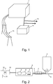
- Figure 1 shows a reduced chart of an energy plant 1, in connection with which the solution according to the present invention can be applied; and Fig. 2 shows a wood gas generator according to an advantageous embodiment of the invention to be applied, for example, in the energy plant of Fig. 1 .
- the energy plant 1 preferably comprises a wood gas generator 2 with a gasifier 3, in which wood or other wood-based fuel 4 is burnt.
- a gasifier 3 in which wood or other wood-based fuel 4 is burnt.
- combustion gases are produced which can also be called wood gases in this context.
- the fuel 4 can be led from a fuel storage 5 to the gasifier 3 by means of, for example, a conveyor 6.
- the fuel 4 can be preheated in a preheater 7, or it can be led without preheating to the gasifier 3.
- the preheater 7 is powered, for example, by the wood gases formed by combustion, wherein the wood gases are led into the preheater.
- the preheater is thus used as a kind of a heat exchanger. As a result, the temperature of the wood gases may drop slightly already in the preheater 7.
- a device for cooling wood gases is also needed, for example a cooler 8, in which the temperature of the wood gases is reduced to a sufficiently low level so that the wood gases can be led into a filter 9.
- the aim is to take away fine particles formed by the combustion of the fuel, which particles may still be entrained in the wood gases leaving the heat exchanger 8.
- the wood gases can be led to a combustion engine 10, which is powered by the wood gases.
- the combustion engine 10 is equipped with a power take-off, such as a shaft 11, which is in a power transmitting connection with a generator 12.
- a power take-off such as a shaft 11, which is in a power transmitting connection with a generator 12.
- This electrical energy can be led by means of cables 13, for example, directly to a consumption location 14 or to an electrical power network 15.
- Heat produced in the energy plant can also be utilized, if necessary, for example for heating buildings, for example by heating a medium to be led into a district heating network 16.
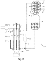
- a device 8 for cooling wood gases according to an advantageous embodiment of the invention in more detail with reference to Fig. 3 .
- Wood gases formed in the combustion of fuel are led along wood gas channels 17 via an inlet 19 into a boiling heat exchanger 18.
- the boiling heat exchanger 18 consists of a container made of, for example, stainless steel and containing cooling liquid channels 20 placed in its inner volume.
- the boiling heat exchanger 18 refers to a heat exchanger in which the cooling medium is heated to boil, wherein the medium is evaporated.
- the temperature of the wood gases in the inlet 19 of the boiling heat exchanger 18 may typically be in the order of 400 to 650°C.
- the wood gases are led along channels 22 to further processing steps in the energy plant 1, for example to a filter 9.
- the temperature of the wood gases is to be reduced in such a way that the temperature of the wood gases in the outlet 21 is not higher than 250°C, preferably between 200 and 250°C. This is achieved advantageously as follows.
- a temperature sensor 23 is used for measuring the temperature of the wood gases coming via the outlet 21. If the temperature exceeds a first predetermined limit value, for example 250°C, a valve 24 is opened, wherein liquid can flow from a liquid tank 25 into the cooling liquid channels 20.
- the liquid level rises in the cooling liquid channels 20, wherein the amount of cooling liquid in that part of the cooling liquid channels 20 which is in contact with the wood gases, increases.
- the cooling capacity of the boiling heat exchanger 18 increases, and the temperature of the wood gases begins to drop.
- the sensor 23 is connected, for example, to a control unit 30, which may be, for example, a computer, a process automation system or the like, examining the measurement signal given by the sensor 23 and utilizing it to determine if there is a need to change the cooling capacity. If there is a need to change the cooling capacity, the control unit 30 generates, for example, a control signal 31 to the valve 24, to effect a corresponding change in the position of the valve 24.
- a control unit 30 may be, for example, a computer, a process automation system or the like, examining the measurement signal given by the sensor 23 and utilizing it to determine if there is a need to change the cooling capacity. If there is a need to change the cooling capacity, the control unit 30 generates, for example, a control signal 31 to the valve 24, to effect a corresponding change in the position of the valve 24.
- the liquid in the cooling liquid channels 20 boils, wherein the steam produced by boiling can be led via steam channels 26 to a condenser 27.
- Heating liquid which is to be heated in the energy plant 1
- the condenser 27 is thus used as a heat exchanger in which thermal energy contained in the steam is transferred to the liquid to be heated.
- the liquid heated in the condenser 27 can be led from the condenser via an outlet 29 e.g. to a district heating network 16 or directly to a consumption location, to be utilized for heating, for example, buildings 15 and/or so-called domestic hot water.
- the steam cooled in the condenser 27 and condensed into a liquid on the walls of the condensing pipes 32 inside the condenser 27 can be led into a liquid tank 25.
- the condensing pipes 32 inside the condenser 27 are advantageously spiral, but also other shapes are feasible.
- the liquid level in the cooling liquid channels 20 may drop, so that by adjusting the valve 24 it is possible to keep the liquid level substantially constant in the cooling liquid channels 20 when there is no need to drop or raise the level to reduce or increase the cooling capacity (that is, the cooling of wood gases) of the boiling heat exchanger 18 (that is, to increase the cooling capacity of the wood gases).
- valve 24 can be adjusted in the closing direction or totally closed, wherein the cooling liquid level in the cooling liquid channels 20 begins to drop, as no new cooling liquid can flow into the cooling liquid channels 20 in place of the liquid removed from there by evaporation.
- the above-presented adjustment of the temperature of the wood gases was thus based on measuring the temperature of wood gases leaving the boiling heat exchanger, but it is obvious that the measurement point can also be placed at another point where a temperature measurement gives a sufficiently reliable control for the adjustment, or there may also be several measurement points. It should also be mentioned that in some embodiments, no temperature measurement is needed, but the adjustment is based on the utilization of predetermined liquid level values. Thus, a guideline value may be known for the liquid level in the cooling liquid channels 20, to have a sufficiently low temperature of wood gases. Such predetermined values may have been determined for example experimentally. However, this arrangement is not necessarily as reliable as the adjustment based on temperature measurements.
- the cooling liquid channels 20 preferably consist of several pipes 20.1 to 20.3 placed in the inner volume of the boiling heat exchanger 18.
- the material, number, cross-sectional form, and or diameter of the pipes may vary in different embodiments, for example according to the cooling capacity required.
- the pipes do not necessarily need to be substantially vertical, but they may also be placed in an inclined position or in some embodiments even horizontally.
- the pipes 20.1 to 20.3 of the cooling liquid channels 20 are arranged in a flow connection, on one hand, with a valve 24 for supplying cooling liquid into the pipes 201 to 20.3 and, on the other hand, with steam channels 26 for removing steam from the pipes 20.1 to 20.3.
- the liquid tank 25 is placed higher than the cooling liquid channels 20 of the boiling heat exchanger 18. As a result, no external power source is needed for supplying cooling liquid from the liquid tank 25 to the cooling liquid channels 20 of the boiling heat exchanger 18, but the flow is implemented by means of gravity, when the valve 24 is at least partly open.
- the liquid tank 25 can be placed at the same level or lower than the cooling liquid channels 20 of the boiling heat exchanger 18, wherein there may be a need to use a pump (not shown) or the like for conveying cooling liquid from the liquid tank 25 to the cooling liquid channels 20 of the boiling heat exchanger 18.
- the cooling liquid channels 20 also comprise a cooling liquid channel 20.4 placed outside the boiling heat exchanger 18, which channel 20.4 may be at least partly transparent so that this cooling liquid channel 20.4 can be used, for example, for monitoring the cooling liquid level in the cooling liquid channels 20.
- boiling heat exchanger 18 Various mixtures of liquids can be used in the boiling heat exchanger 18 for achieving a desired boiling point. If the 100°C boiling point of water is too low, it can be raised by means of, for example, a glycol mixture. Lowering the boiling can be implemented, for example, by adding ethanol, whose boiling point is about 78°C, to the cooling liquid circulation.
- one aim of the cooling device according to the invention is to lower the temperature of the wood gases from a range between 400 and 650°C to a range between 200 and 250°C, so that impurities contained in the gas can be filtered out before the gas is used as fuel in the combustion engine 10 rotating the generator 12.
Landscapes
- Engineering & Computer Science (AREA)
- Chemical & Material Sciences (AREA)
- Mechanical Engineering (AREA)
- Thermal Sciences (AREA)
- Physics & Mathematics (AREA)
- Combustion & Propulsion (AREA)
- General Engineering & Computer Science (AREA)
- Life Sciences & Earth Sciences (AREA)
- Sustainable Development (AREA)
- Oil, Petroleum & Natural Gas (AREA)
- Organic Chemistry (AREA)
- General Chemical & Material Sciences (AREA)
- Transportation (AREA)
- Chemical Kinetics & Catalysis (AREA)
- Sustainable Energy (AREA)
- Chemical And Physical Treatments For Wood And The Like (AREA)
Priority Applications (1)
| Application Number | Priority Date | Filing Date | Title |
|---|---|---|---|
| PL11774067T PL2596286T3 (pl) | 2010-07-22 | 2011-07-07 | Sposób i urządzenie do schładzania gazów drzewnych |
Applications Claiming Priority (2)
| Application Number | Priority Date | Filing Date | Title |
|---|---|---|---|
| FI20105818A FI123858B (fi) | 2010-07-22 | 2010-07-22 | Menetelmä ja laitteisto puukaasujen jäähdyttämiseksi |
| PCT/FI2011/050640 WO2012010742A2 (en) | 2010-07-22 | 2011-07-07 | A method and a device for cooling wood gases |
Publications (2)
| Publication Number | Publication Date |
|---|---|
| EP2596286A2 EP2596286A2 (en) | 2013-05-29 |
| EP2596286B1 true EP2596286B1 (en) | 2017-10-18 |
Family
ID=42555511
Family Applications (1)
| Application Number | Title | Priority Date | Filing Date |
|---|---|---|---|
| EP11774067.0A Not-in-force EP2596286B1 (en) | 2010-07-22 | 2011-07-07 | A method and a device for cooling wood gases |
Country Status (5)
| Country | Link |
|---|---|
| EP (1) | EP2596286B1 (pl) |
| FI (1) | FI123858B (pl) |
| NO (1) | NO2596286T3 (pl) |
| PL (1) | PL2596286T3 (pl) |
| WO (1) | WO2012010742A2 (pl) |
Families Citing this family (1)
| Publication number | Priority date | Publication date | Assignee | Title |
|---|---|---|---|---|
| CA3033810C (en) | 2016-08-25 | 2022-07-12 | Volter Oy | A combined heat and power plant and a method for improving the burning process in a combined heat and power plant |
Family Cites Families (5)
| Publication number | Priority date | Publication date | Assignee | Title |
|---|---|---|---|---|
| GB1293279A (en) | 1969-11-15 | 1972-10-18 | Magyar Hajo Es Darugyar | Heat transfer apparatus for the utilization of the heat content of exhaust gases |
| US4270493A (en) | 1979-01-08 | 1981-06-02 | Combustion Engineering, Inc. | Steam generating heat exchanger |
| GB2115129B (en) | 1982-02-15 | 1984-10-31 | Shell Int Research | Process for the cooling of small particles-containing gases |
| JPH0228792B2 (ja) * | 1984-06-06 | 1990-06-26 | Matsushita Electric Ind Co Ltd | Netsuhansosochi |
| DE102004030368A1 (de) | 2004-06-23 | 2006-01-12 | Kirchner, Hans Walter, Dipl.-Ing. | Kontinuerlich arbeitender Gleichstrom-Festbettvergaser für Festbrennstoffe mit Mantelrohrwärmetauscher |
-
2010
- 2010-07-22 FI FI20105818A patent/FI123858B/fi not_active IP Right Cessation
-
2011
- 2011-07-07 PL PL11774067T patent/PL2596286T3/pl unknown
- 2011-07-07 EP EP11774067.0A patent/EP2596286B1/en not_active Not-in-force
- 2011-07-07 WO PCT/FI2011/050640 patent/WO2012010742A2/en not_active Ceased
- 2011-07-07 NO NO11774067A patent/NO2596286T3/no unknown
Non-Patent Citations (1)
| Title |
|---|
| None * |
Also Published As
| Publication number | Publication date |
|---|---|
| PL2596286T3 (pl) | 2018-03-30 |
| FI123858B (fi) | 2013-11-29 |
| FI20105818A0 (fi) | 2010-07-22 |
| NO2596286T3 (pl) | 2018-03-17 |
| EP2596286A2 (en) | 2013-05-29 |
| FI20105818A7 (fi) | 2012-01-23 |
| WO2012010742A3 (en) | 2013-01-24 |
| WO2012010742A2 (en) | 2012-01-26 |
Similar Documents
| Publication | Publication Date | Title |
|---|---|---|
| CN102564095B (zh) | 一种低压过热蒸汽干燥褐煤的装置和方法 | |
| EP2281164B1 (fr) | Procédé de fabrication de clinker de ciment et installation de fabrication de clinker de ciment. | |
| CN101976987B (zh) | 以热载体为热媒的工业余热半导体发电方法及装置 | |
| CN101398267A (zh) | 内循环复合相变换热器 | |
| CN102410527A (zh) | 用于锅炉烟气余热回收的复合相变换热器 | |
| CN1060335A (zh) | 用于组合循环发电厂的排气器热交换器 | |
| KR101249203B1 (ko) | 증기 발생 장치 | |
| CN109593561B (zh) | 一种水冷壁气化炉的烘炉系统及烘炉方法 | |
| CN117946760A (zh) | 一种超临界水热转化生物质废弃物处理多联产系统及方法 | |
| EP0523105A1 (en) | PROCESS AND APPARATUS FOR GENERATING HEAT AND ELECTRICITY IN A SULPHATE PULP MIXER. | |
| EP2596286B1 (en) | A method and a device for cooling wood gases | |
| CN112723709A (zh) | 一种两段式电磁加热的含油污泥干化热解系统 | |
| JP2005146185A (ja) | 植物系バイオマス資源利用設備 | |
| CN204400923U (zh) | 一种生物质气化多联产装置 | |
| CN108884991A (zh) | 锅炉的运转方法和锅炉设备 | |
| KR101937192B1 (ko) | 폐플라스틱 유화 공정에서 발생하는 폐가스를 이용한 에너지 생산 시스템 및 그 방법 | |
| EP3415816B2 (en) | A method and a system for extending the load range of a power plant comprising a boiler supplying steam to a steam turbine | |
| CN214457580U (zh) | 一种两段式电磁加热的含油污泥干化热解系统 | |
| CN101974363B (zh) | 一种废工业油料的回收处理方法及实施该方法的设备 | |
| CN208457942U (zh) | 一种用于生物质气化高温燃气降温的蒸汽冷却系统 | |
| CN207815275U (zh) | 一种半焦预热利用系统 | |
| Iliev et al. | Waste Heat Recovery from Boilers and Furnaces Running on Biomass Waste Products | |
| CN104388122B (zh) | 一种生物质气化多联产方法及其装置 | |
| FR2921717A1 (fr) | Dispositif de recuperation de calories des gaz chauds dans une installation de chauffage avec une chaudiere | |
| CN2606839Y (zh) | 真空相变重力式热管锅炉 |
Legal Events
| Date | Code | Title | Description |
|---|---|---|---|
| PUAI | Public reference made under article 153(3) epc to a published international application that has entered the european phase |
Free format text: ORIGINAL CODE: 0009012 |
|
| 17P | Request for examination filed |
Effective date: 20130218 |
|
| AK | Designated contracting states |
Kind code of ref document: A2 Designated state(s): AL AT BE BG CH CY CZ DE DK EE ES FI FR GB GR HR HU IE IS IT LI LT LU LV MC MK MT NL NO PL PT RO RS SE SI SK SM TR |
|
| RAP1 | Party data changed (applicant data changed or rights of an application transferred) |
Owner name: VOLTER OY |
|
| DAX | Request for extension of the european patent (deleted) | ||
| GRAP | Despatch of communication of intention to grant a patent |
Free format text: ORIGINAL CODE: EPIDOSNIGR1 |
|
| STAA | Information on the status of an ep patent application or granted ep patent |
Free format text: STATUS: GRANT OF PATENT IS INTENDED |
|
| INTG | Intention to grant announced |
Effective date: 20170515 |
|
| GRAS | Grant fee paid |
Free format text: ORIGINAL CODE: EPIDOSNIGR3 |
|
| GRAA | (expected) grant |
Free format text: ORIGINAL CODE: 0009210 |
|
| STAA | Information on the status of an ep patent application or granted ep patent |
Free format text: STATUS: THE PATENT HAS BEEN GRANTED |
|
| AK | Designated contracting states |
Kind code of ref document: B1 Designated state(s): AL AT BE BG CH CY CZ DE DK EE ES FI FR GB GR HR HU IE IS IT LI LT LU LV MC MK MT NL NO PL PT RO RS SE SI SK SM TR |
|
| REG | Reference to a national code |
Ref country code: GB Ref legal event code: FG4D |
|
| REG | Reference to a national code |
Ref country code: CH Ref legal event code: EP |
|
| REG | Reference to a national code |
Ref country code: AT Ref legal event code: REF Ref document number: 938287 Country of ref document: AT Kind code of ref document: T Effective date: 20171115 Ref country code: IE Ref legal event code: FG4D |
|
| REG | Reference to a national code |
Ref country code: DE Ref legal event code: R096 Ref document number: 602011042526 Country of ref document: DE |
|
| REG | Reference to a national code |
Ref country code: SE Ref legal event code: TRGR |
|
| REG | Reference to a national code |
Ref country code: NL Ref legal event code: MP Effective date: 20171018 |
|
| REG | Reference to a national code |
Ref country code: LT Ref legal event code: MG4D Ref country code: NO Ref legal event code: T2 Effective date: 20171018 |
|
| REG | Reference to a national code |
Ref country code: EE Ref legal event code: FG4A Ref document number: E014955 Country of ref document: EE Effective date: 20180116 |
|
| PG25 | Lapsed in a contracting state [announced via postgrant information from national office to epo] |
Ref country code: NL Free format text: LAPSE BECAUSE OF FAILURE TO SUBMIT A TRANSLATION OF THE DESCRIPTION OR TO PAY THE FEE WITHIN THE PRESCRIBED TIME-LIMIT Effective date: 20171018 |
|
| PG25 | Lapsed in a contracting state [announced via postgrant information from national office to epo] |
Ref country code: FI Free format text: LAPSE BECAUSE OF FAILURE TO SUBMIT A TRANSLATION OF THE DESCRIPTION OR TO PAY THE FEE WITHIN THE PRESCRIBED TIME-LIMIT Effective date: 20171018 Ref country code: LT Free format text: LAPSE BECAUSE OF FAILURE TO SUBMIT A TRANSLATION OF THE DESCRIPTION OR TO PAY THE FEE WITHIN THE PRESCRIBED TIME-LIMIT Effective date: 20171018 Ref country code: ES Free format text: LAPSE BECAUSE OF FAILURE TO SUBMIT A TRANSLATION OF THE DESCRIPTION OR TO PAY THE FEE WITHIN THE PRESCRIBED TIME-LIMIT Effective date: 20171018 |
|
| PG25 | Lapsed in a contracting state [announced via postgrant information from national office to epo] |
Ref country code: GR Free format text: LAPSE BECAUSE OF FAILURE TO SUBMIT A TRANSLATION OF THE DESCRIPTION OR TO PAY THE FEE WITHIN THE PRESCRIBED TIME-LIMIT Effective date: 20180119 Ref country code: RS Free format text: LAPSE BECAUSE OF FAILURE TO SUBMIT A TRANSLATION OF THE DESCRIPTION OR TO PAY THE FEE WITHIN THE PRESCRIBED TIME-LIMIT Effective date: 20171018 Ref country code: LV Free format text: LAPSE BECAUSE OF FAILURE TO SUBMIT A TRANSLATION OF THE DESCRIPTION OR TO PAY THE FEE WITHIN THE PRESCRIBED TIME-LIMIT Effective date: 20171018 Ref country code: BG Free format text: LAPSE BECAUSE OF FAILURE TO SUBMIT A TRANSLATION OF THE DESCRIPTION OR TO PAY THE FEE WITHIN THE PRESCRIBED TIME-LIMIT Effective date: 20180118 Ref country code: HR Free format text: LAPSE BECAUSE OF FAILURE TO SUBMIT A TRANSLATION OF THE DESCRIPTION OR TO PAY THE FEE WITHIN THE PRESCRIBED TIME-LIMIT Effective date: 20171018 Ref country code: IS Free format text: LAPSE BECAUSE OF FAILURE TO SUBMIT A TRANSLATION OF THE DESCRIPTION OR TO PAY THE FEE WITHIN THE PRESCRIBED TIME-LIMIT Effective date: 20180218 |
|
| REG | Reference to a national code |
Ref country code: DE Ref legal event code: R097 Ref document number: 602011042526 Country of ref document: DE |
|
| PG25 | Lapsed in a contracting state [announced via postgrant information from national office to epo] |
Ref country code: CZ Free format text: LAPSE BECAUSE OF FAILURE TO SUBMIT A TRANSLATION OF THE DESCRIPTION OR TO PAY THE FEE WITHIN THE PRESCRIBED TIME-LIMIT Effective date: 20171018 Ref country code: SK Free format text: LAPSE BECAUSE OF FAILURE TO SUBMIT A TRANSLATION OF THE DESCRIPTION OR TO PAY THE FEE WITHIN THE PRESCRIBED TIME-LIMIT Effective date: 20171018 Ref country code: DK Free format text: LAPSE BECAUSE OF FAILURE TO SUBMIT A TRANSLATION OF THE DESCRIPTION OR TO PAY THE FEE WITHIN THE PRESCRIBED TIME-LIMIT Effective date: 20171018 |
|
| PLBE | No opposition filed within time limit |
Free format text: ORIGINAL CODE: 0009261 |
|
| STAA | Information on the status of an ep patent application or granted ep patent |
Free format text: STATUS: NO OPPOSITION FILED WITHIN TIME LIMIT |
|
| PG25 | Lapsed in a contracting state [announced via postgrant information from national office to epo] |
Ref country code: RO Free format text: LAPSE BECAUSE OF FAILURE TO SUBMIT A TRANSLATION OF THE DESCRIPTION OR TO PAY THE FEE WITHIN THE PRESCRIBED TIME-LIMIT Effective date: 20171018 Ref country code: SM Free format text: LAPSE BECAUSE OF FAILURE TO SUBMIT A TRANSLATION OF THE DESCRIPTION OR TO PAY THE FEE WITHIN THE PRESCRIBED TIME-LIMIT Effective date: 20171018 |
|
| PGFP | Annual fee paid to national office [announced via postgrant information from national office to epo] |
Ref country code: PL Payment date: 20180607 Year of fee payment: 8 |
|
| 26N | No opposition filed |
Effective date: 20180719 |
|
| PGFP | Annual fee paid to national office [announced via postgrant information from national office to epo] |
Ref country code: IE Payment date: 20180717 Year of fee payment: 8 Ref country code: NO Payment date: 20180718 Year of fee payment: 8 Ref country code: EE Payment date: 20180724 Year of fee payment: 8 Ref country code: DE Payment date: 20180718 Year of fee payment: 8 Ref country code: IT Payment date: 20180720 Year of fee payment: 8 |
|
| PG25 | Lapsed in a contracting state [announced via postgrant information from national office to epo] |
Ref country code: SI Free format text: LAPSE BECAUSE OF FAILURE TO SUBMIT A TRANSLATION OF THE DESCRIPTION OR TO PAY THE FEE WITHIN THE PRESCRIBED TIME-LIMIT Effective date: 20171018 |
|
| PGFP | Annual fee paid to national office [announced via postgrant information from national office to epo] |
Ref country code: AT Payment date: 20180724 Year of fee payment: 8 Ref country code: GB Payment date: 20180717 Year of fee payment: 8 Ref country code: SE Payment date: 20180717 Year of fee payment: 8 |
|
| REG | Reference to a national code |
Ref country code: CH Ref legal event code: PL |
|
| PG25 | Lapsed in a contracting state [announced via postgrant information from national office to epo] |
Ref country code: LU Free format text: LAPSE BECAUSE OF NON-PAYMENT OF DUE FEES Effective date: 20180707 Ref country code: MC Free format text: LAPSE BECAUSE OF FAILURE TO SUBMIT A TRANSLATION OF THE DESCRIPTION OR TO PAY THE FEE WITHIN THE PRESCRIBED TIME-LIMIT Effective date: 20171018 |
|
| REG | Reference to a national code |
Ref country code: BE Ref legal event code: MM Effective date: 20180731 |
|
| PG25 | Lapsed in a contracting state [announced via postgrant information from national office to epo] |
Ref country code: FR Free format text: LAPSE BECAUSE OF NON-PAYMENT OF DUE FEES Effective date: 20180731 Ref country code: CH Free format text: LAPSE BECAUSE OF NON-PAYMENT OF DUE FEES Effective date: 20180731 Ref country code: LI Free format text: LAPSE BECAUSE OF NON-PAYMENT OF DUE FEES Effective date: 20180731 |
|
| PG25 | Lapsed in a contracting state [announced via postgrant information from national office to epo] |
Ref country code: BE Free format text: LAPSE BECAUSE OF NON-PAYMENT OF DUE FEES Effective date: 20180731 |
|
| PG25 | Lapsed in a contracting state [announced via postgrant information from national office to epo] |
Ref country code: MT Free format text: LAPSE BECAUSE OF NON-PAYMENT OF DUE FEES Effective date: 20180707 |
|
| REG | Reference to a national code |
Ref country code: DE Ref legal event code: R119 Ref document number: 602011042526 Country of ref document: DE |
|
| REG | Reference to a national code |
Ref country code: EE Ref legal event code: MM4A Ref document number: E014955 Country of ref document: EE Effective date: 20190731 |
|
| REG | Reference to a national code |
Ref country code: NO Ref legal event code: MMEP |
|
| REG | Reference to a national code |
Ref country code: SE Ref legal event code: EUG |
|
| REG | Reference to a national code |
Ref country code: AT Ref legal event code: MM01 Ref document number: 938287 Country of ref document: AT Kind code of ref document: T Effective date: 20190707 |
|
| GBPC | Gb: european patent ceased through non-payment of renewal fee |
Effective date: 20190707 |
|
| PG25 | Lapsed in a contracting state [announced via postgrant information from national office to epo] |
Ref country code: TR Free format text: LAPSE BECAUSE OF FAILURE TO SUBMIT A TRANSLATION OF THE DESCRIPTION OR TO PAY THE FEE WITHIN THE PRESCRIBED TIME-LIMIT Effective date: 20171018 |
|
| PG25 | Lapsed in a contracting state [announced via postgrant information from national office to epo] |
Ref country code: DE Free format text: LAPSE BECAUSE OF NON-PAYMENT OF DUE FEES Effective date: 20200201 Ref country code: EE Free format text: LAPSE BECAUSE OF NON-PAYMENT OF DUE FEES Effective date: 20190731 Ref country code: GB Free format text: LAPSE BECAUSE OF NON-PAYMENT OF DUE FEES Effective date: 20190707 Ref country code: AT Free format text: LAPSE BECAUSE OF NON-PAYMENT OF DUE FEES Effective date: 20190707 Ref country code: NO Free format text: LAPSE BECAUSE OF NON-PAYMENT OF DUE FEES Effective date: 20190731 Ref country code: SE Free format text: LAPSE BECAUSE OF NON-PAYMENT OF DUE FEES Effective date: 20190708 |
|
| PG25 | Lapsed in a contracting state [announced via postgrant information from national office to epo] |
Ref country code: HU Free format text: LAPSE BECAUSE OF FAILURE TO SUBMIT A TRANSLATION OF THE DESCRIPTION OR TO PAY THE FEE WITHIN THE PRESCRIBED TIME-LIMIT; INVALID AB INITIO Effective date: 20110707 Ref country code: PT Free format text: LAPSE BECAUSE OF FAILURE TO SUBMIT A TRANSLATION OF THE DESCRIPTION OR TO PAY THE FEE WITHIN THE PRESCRIBED TIME-LIMIT Effective date: 20171018 |
|
| PG25 | Lapsed in a contracting state [announced via postgrant information from national office to epo] |
Ref country code: CY Free format text: LAPSE BECAUSE OF FAILURE TO SUBMIT A TRANSLATION OF THE DESCRIPTION OR TO PAY THE FEE WITHIN THE PRESCRIBED TIME-LIMIT Effective date: 20171018 Ref country code: MK Free format text: LAPSE BECAUSE OF NON-PAYMENT OF DUE FEES Effective date: 20171018 |
|
| PG25 | Lapsed in a contracting state [announced via postgrant information from national office to epo] |
Ref country code: AL Free format text: LAPSE BECAUSE OF FAILURE TO SUBMIT A TRANSLATION OF THE DESCRIPTION OR TO PAY THE FEE WITHIN THE PRESCRIBED TIME-LIMIT Effective date: 20171018 Ref country code: IE Free format text: LAPSE BECAUSE OF NON-PAYMENT OF DUE FEES Effective date: 20190707 |
|
| PG25 | Lapsed in a contracting state [announced via postgrant information from national office to epo] |
Ref country code: IT Free format text: LAPSE BECAUSE OF NON-PAYMENT OF DUE FEES Effective date: 20190707 |
|
| REG | Reference to a national code |
Ref country code: AT Ref legal event code: UEP Ref document number: 938287 Country of ref document: AT Kind code of ref document: T Effective date: 20171018 |
|
| PG25 | Lapsed in a contracting state [announced via postgrant information from national office to epo] |
Ref country code: PL Free format text: LAPSE BECAUSE OF NON-PAYMENT OF DUE FEES Effective date: 20190707 |