EP2596259B1 - Constant velocity joint assembly and method of securing a shaft to the assembly - Google Patents
Constant velocity joint assembly and method of securing a shaft to the assembly Download PDFInfo
- Publication number
- EP2596259B1 EP2596259B1 EP11727341.7A EP11727341A EP2596259B1 EP 2596259 B1 EP2596259 B1 EP 2596259B1 EP 11727341 A EP11727341 A EP 11727341A EP 2596259 B1 EP2596259 B1 EP 2596259B1
- Authority
- EP
- European Patent Office
- Prior art keywords
- shaft
- race
- assembly
- boot
- outer race
- Prior art date
- Legal status (The legal status is an assumption and is not a legal conclusion. Google has not performed a legal analysis and makes no representation as to the accuracy of the status listed.)
- Not-in-force
Links
- 238000000034 method Methods 0.000 title description 9
- 239000011800 void material Substances 0.000 claims description 2
- 239000000428 dust Substances 0.000 description 8
- 238000003466 welding Methods 0.000 description 7
- 239000000853 adhesive Substances 0.000 description 6
- 230000001070 adhesive effect Effects 0.000 description 6
- 230000002093 peripheral effect Effects 0.000 description 4
- 239000003990 capacitor Substances 0.000 description 3
- 238000004073 vulcanization Methods 0.000 description 3
- 229910000838 Al alloy Inorganic materials 0.000 description 2
- 230000000712 assembly Effects 0.000 description 2
- 238000000429 assembly Methods 0.000 description 2
- 230000008569 process Effects 0.000 description 2
- 230000002787 reinforcement Effects 0.000 description 2
- 239000000565 sealant Substances 0.000 description 2
- XAGFODPZIPBFFR-UHFFFAOYSA-N aluminium Chemical compound [Al] XAGFODPZIPBFFR-UHFFFAOYSA-N 0.000 description 1
- 229910052782 aluminium Inorganic materials 0.000 description 1
- 230000004888 barrier function Effects 0.000 description 1
- 230000005540 biological transmission Effects 0.000 description 1
- 239000004020 conductor Substances 0.000 description 1
- 238000002788 crimping Methods 0.000 description 1
- 230000000694 effects Effects 0.000 description 1
- 230000008030 elimination Effects 0.000 description 1
- 238000003379 elimination reaction Methods 0.000 description 1
- 239000012212 insulator Substances 0.000 description 1
- 239000007788 liquid Substances 0.000 description 1
- 238000004519 manufacturing process Methods 0.000 description 1
- 230000009467 reduction Effects 0.000 description 1
Images


Classifications
-
- F—MECHANICAL ENGINEERING; LIGHTING; HEATING; WEAPONS; BLASTING
- F16—ENGINEERING ELEMENTS AND UNITS; GENERAL MEASURES FOR PRODUCING AND MAINTAINING EFFECTIVE FUNCTIONING OF MACHINES OR INSTALLATIONS; THERMAL INSULATION IN GENERAL
- F16D—COUPLINGS FOR TRANSMITTING ROTATION; CLUTCHES; BRAKES
- F16D3/00—Yielding couplings, i.e. with means permitting movement between the connected parts during the drive
- F16D3/84—Shrouds, e.g. casings, covers; Sealing means specially adapted therefor
-
- B—PERFORMING OPERATIONS; TRANSPORTING
- B23—MACHINE TOOLS; METAL-WORKING NOT OTHERWISE PROVIDED FOR
- B23K—SOLDERING OR UNSOLDERING; WELDING; CLADDING OR PLATING BY SOLDERING OR WELDING; CUTTING BY APPLYING HEAT LOCALLY, e.g. FLAME CUTTING; WORKING BY LASER BEAM
- B23K20/00—Non-electric welding by applying impact or other pressure, with or without the application of heat, e.g. cladding or plating
- B23K20/06—Non-electric welding by applying impact or other pressure, with or without the application of heat, e.g. cladding or plating by means of high energy impulses, e.g. magnetic energy
-
- F—MECHANICAL ENGINEERING; LIGHTING; HEATING; WEAPONS; BLASTING
- F16—ENGINEERING ELEMENTS AND UNITS; GENERAL MEASURES FOR PRODUCING AND MAINTAINING EFFECTIVE FUNCTIONING OF MACHINES OR INSTALLATIONS; THERMAL INSULATION IN GENERAL
- F16D—COUPLINGS FOR TRANSMITTING ROTATION; CLUTCHES; BRAKES
- F16D3/00—Yielding couplings, i.e. with means permitting movement between the connected parts during the drive
- F16D3/84—Shrouds, e.g. casings, covers; Sealing means specially adapted therefor
- F16D3/843—Shrouds, e.g. casings, covers; Sealing means specially adapted therefor enclosed covers
- F16D3/845—Shrouds, e.g. casings, covers; Sealing means specially adapted therefor enclosed covers allowing relative movement of joint parts due to the flexing of the cover
-
- F—MECHANICAL ENGINEERING; LIGHTING; HEATING; WEAPONS; BLASTING
- F16—ENGINEERING ELEMENTS AND UNITS; GENERAL MEASURES FOR PRODUCING AND MAINTAINING EFFECTIVE FUNCTIONING OF MACHINES OR INSTALLATIONS; THERMAL INSULATION IN GENERAL
- F16D—COUPLINGS FOR TRANSMITTING ROTATION; CLUTCHES; BRAKES
- F16D3/00—Yielding couplings, i.e. with means permitting movement between the connected parts during the drive
-
- F—MECHANICAL ENGINEERING; LIGHTING; HEATING; WEAPONS; BLASTING
- F16—ENGINEERING ELEMENTS AND UNITS; GENERAL MEASURES FOR PRODUCING AND MAINTAINING EFFECTIVE FUNCTIONING OF MACHINES OR INSTALLATIONS; THERMAL INSULATION IN GENERAL
- F16D—COUPLINGS FOR TRANSMITTING ROTATION; CLUTCHES; BRAKES
- F16D3/00—Yielding couplings, i.e. with means permitting movement between the connected parts during the drive
- F16D3/16—Universal joints in which flexibility is produced by means of pivots or sliding or rolling connecting parts
- F16D3/20—Universal joints in which flexibility is produced by means of pivots or sliding or rolling connecting parts one coupling part entering a sleeve of the other coupling part and connected thereto by sliding or rolling members
- F16D3/22—Universal joints in which flexibility is produced by means of pivots or sliding or rolling connecting parts one coupling part entering a sleeve of the other coupling part and connected thereto by sliding or rolling members the rolling members being balls, rollers, or the like, guided in grooves or sockets in both coupling parts
-
- F—MECHANICAL ENGINEERING; LIGHTING; HEATING; WEAPONS; BLASTING
- F16—ENGINEERING ELEMENTS AND UNITS; GENERAL MEASURES FOR PRODUCING AND MAINTAINING EFFECTIVE FUNCTIONING OF MACHINES OR INSTALLATIONS; THERMAL INSULATION IN GENERAL
- F16D—COUPLINGS FOR TRANSMITTING ROTATION; CLUTCHES; BRAKES
- F16D3/00—Yielding couplings, i.e. with means permitting movement between the connected parts during the drive
- F16D3/16—Universal joints in which flexibility is produced by means of pivots or sliding or rolling connecting parts
- F16D3/20—Universal joints in which flexibility is produced by means of pivots or sliding or rolling connecting parts one coupling part entering a sleeve of the other coupling part and connected thereto by sliding or rolling members
- F16D3/22—Universal joints in which flexibility is produced by means of pivots or sliding or rolling connecting parts one coupling part entering a sleeve of the other coupling part and connected thereto by sliding or rolling members the rolling members being balls, rollers, or the like, guided in grooves or sockets in both coupling parts
- F16D3/223—Universal joints in which flexibility is produced by means of pivots or sliding or rolling connecting parts one coupling part entering a sleeve of the other coupling part and connected thereto by sliding or rolling members the rolling members being balls, rollers, or the like, guided in grooves or sockets in both coupling parts the rolling members being guided in grooves in both coupling parts
- F16D2003/22316—Means for fastening or attaching the bellows or gaiters
-
- Y—GENERAL TAGGING OF NEW TECHNOLOGICAL DEVELOPMENTS; GENERAL TAGGING OF CROSS-SECTIONAL TECHNOLOGIES SPANNING OVER SEVERAL SECTIONS OF THE IPC; TECHNICAL SUBJECTS COVERED BY FORMER USPC CROSS-REFERENCE ART COLLECTIONS [XRACs] AND DIGESTS
- Y10—TECHNICAL SUBJECTS COVERED BY FORMER USPC
- Y10T—TECHNICAL SUBJECTS COVERED BY FORMER US CLASSIFICATION
- Y10T29/00—Metal working
- Y10T29/49—Method of mechanical manufacture
- Y10T29/49826—Assembling or joining
- Y10T29/49908—Joining by deforming
- Y10T29/49925—Inward deformation of aperture or hollow body wall
Definitions
- the present invention relates to a constant velocity joint assembly and a method of securing a shaft to the assembly.
- Constant velocity joints allow a rotating shaft to transmit power through a variable angle, at constant rotational speed, without an appreciable increase in friction or play.
- the prior art joints are generally disk shaped structures that are bolted to a flange or have an extension off of the back of the joint for a wire, laser or magnetic arc weld.
- the relatively thin nature of the prior art designs do not lend themselves to providing a sufficient welding surface upon which a tube, such as a drive shaft tube, can be connected directly therewith using a lap joint or without additional structures.
- the prior art designs also typically utilize an elastomeric boot to prevent dust, dirt and moisture from entering the joint.
- the prior art boots extend from the joint face or from a boot can mounted to the face which leaves them exposed to many different environments and conditions where they can be easily damaged. It would, therefore, be advantageous for a joint design to have a way of protecting the boot from damage.
- a joint is lightweight. Weight savings can be achieved by reducing or eliminating the hardware, such as bolts and flanges, required to connect the joint to tubes or other structures. It can be appreciated that with the reduction or elimination of connection hardware, cost savings can be achieved as well as a joint that has a cleaner appearance.
- WO 2007/023803 A1 relates to a flexible boot enabling the simplification of boot mounting operation and boot manufacturing steps.
- the flexible boot is disposed between the outer joint member and the intermediate outer periphery of the shaft of a constant velocity universal joint storing torque transmission members between the outer joint member and an inner joint member and formed by extending the shaft connected to the inner joint member to the outside of the joint.
- the flexible boot comprises a tubular small diameter part fixed to the outer peripheral surface of the shaft, a large diameter part fitted to the inner peripheral surface of the outer joint member through a reinforcement ring part, and a bellows part connecting the small diameter part to the large diameter part.
- the flexible boot is characterized in that the outer peripheral surface of the reinforcement ring part is fitted to the inner peripheral surface of the outer joint member.
- the invention is directed toward a constant velocity joint assembly according to claim 1.
- Another example is directed toward a method of securing a shaft to the constant velocity joint assembly.
- This method may comprise the steps of providing the outer race as described above and also having an outer surface.
- the method may further comprise the step of locating the outer race within a hollow end portion of a shaft.
- An inductor may be located axially relative to the outer race and the tube where it is then energized to magnetically pulse weld the two together.
- Fig. 1 one embodiment of a constant velocity joint assembly 10 is depicted.
- Fig. 1 is for illustrative purposes only; other constant velocity joints including double offset, N+N, Rzeppa, plunging, tripod, undercut free, cross-groove and Weiss may be used with the present invention without limitation.
- the assembly 10 comprises a shaft 12, such as a stub shaft, an inner race 14, an outer race 16, a cage 18 and ball bearings 20.
- the assembly 10 may, in one embodiment, also comprise a boot can insert 22, a boot 24 and a dust cap 26.
- the assembly may also comprise a drive shaft 28, as will be described below.
- the shaft 12 is provided with a first end 30, a first end portion 32, a second end 34, a second end portion 36 and a body portion 38 located between the first and second ends 30, 34.
- the first end 30 may have radiused or chamfered corners 40, or the corners 40 may have ninety degree angles.
- the first end portion 32 defines a substantially constant outer diameter 42 of the shaft 12.
- the second end portion 36 may have an expanding section 44, formed in a unitary fashion with the body portion 38.
- One or more circumferential grooves 46 may be located in either the first end portion 32 or the second end portion 36, or both.
- the end portions 32, 36 otherwise have substantially constant outer diameters.
- the expanding section 44 has an outer surface 48 upon which, or with which, a tube (not shown) may be connected.
- the tube may be connected mechanically to the outer surface 48 of the expanding section 44 and/or by welding, friction fitting, crimping, adhesives or combinations of the foregoing.
- the inner race 14 is provided with an inner surface 50, an outer surface 52, a first end 54 and a second end 56.
- the inner surface 50 of the inner race 14 is secured to the first end portion 32 of the shaft 12.
- the first end 54 of the inner race 14 is axially offset from the first end 30 of the shaft 12.
- the outer surface 52 of the inner race 14 is provided with a plurality of circumferentially spaced apart grooves 58.
- the grooves 58 preferably extend from the first end 54 of the inner race 14 to the second end 56 of the inner race 14.
- the outer surface 52 of the inner race 14 may have a curvilinear shape.
- the inner surface 50, the outer surface 52, the ends 54, 56 and the grooves 58 are unitary with one another.
- the cage 18 is provided with a first end 60, a second end 62, an inner surface 64 and an outer surface 66.
- a plurality of apertures 68 is located in the cage 18 and they extend from the inner surface 64 to the outer surface 66.
- the first end 60 of the cage 18 is shown axially aligned with the first end 30 of the shaft 12. Further, the first end 60 of the cage 18 extends axially beyond the first end 54 of the inner race 14. The second end 62 of the cage 18 extends axially beyond the second end 56 of the inner race 14.
- the inner surface 64 and the outer surface 66 of the cage 18 may be curvilinear.
- each of the ends 60, 62 and surfaces 64, 66 are unitary with one another.
- the outer race has an inner surface 70, an outer surface 72, a first end 74, a second end 76, a first body portion 78 and a second body portion 80.
- each of the foregoing are unitary with one another.
- the outer race 70 has an overall cylindrical shape formed by the inner surface 70 and the outer surface 72.
- the first end 74 of the outer race 16 is slightly axially offset from the first end 60 of the cage 18 and the first end 30 of the shaft 12.
- the first body portion 78 extends from the first end 74 axially inwardly into the race 16.
- the inner surface 70 at the first body portion 78 comprises a plurality of grooves 82 and may be curvilinear.
- the number of grooves 82 is equal to the number of grooves 58 on the inner race 14.
- the inner surface 70 of the second body portion 80 has a substantially constant diameter portion 84. As such, it forms a cylindrical type extension, or boot can 86, from the first body portion 78.
- the substantially constant diameter portion 84 of the inner surface 70 is preferably parallel with the diameter 42 of the shaft 12 in one embodiment while the assembly 10 is in the orientation depicted in Fig. 1 .
- the substantially constant diameter portion 84 of the inner surface 70 is preferably parallel with the drive shaft 28 in any orientation of the assembly 10.
- One ball bearing 20 may be located within each aperture 68 of the cage 18. Each ball bearing 20 preferably rotates and moves along one of the grooves 82 of the outer race 16 and one of the grooves 58 in the inner race 14.
- a longitudinal axis 90 of the shaft 12 may be aligned with a longitudinal axis 92 of the outer race 16.
- the joint assembly 10 is a zero articulation angle orientation.
- the outer race 16 may be located at an angle with respect to the shaft 12 or vice versa.
- the two axes 90, 92 may be at an angle with respect to one another.
- the inner surface 70 of the outer race 16 defines an inner void 94 in which at least the first end 32 portion of the shaft 12, the inner race 14, the cage 18 and the ball bearings 20 reside.
- the second end 76 of the outer race 16 may form a ninety degree angle with respect to the inner surface 70 of the second body portion 80. Other angles other than ninety degrees are permissible.
- the outer surface 72 of the outer race 16 has a portion located radially outward from the substantially constant diameter portion 84.
- a depression 98 in the above-mentioned portion of the outer surface 72 is provided.
- At least one step 100 is located directly beside the depression 98, adjacent the second end 76, and extends radially outward therefrom. In the depicted embodiment, two steps 100 are provided, although any number of steps are permissible.
- the outer surface 72 of the outer race 16 also has a substantially constant outer diameter portion 102 located radially outward from the plurality of grooves 82.
- the constant outer diameter portion 102 may extend from the depression 98 to the first end 74 or, as shown in Fig. 1 , a recess 104 for the dust cap 26 and seal 106 may be provided therein.
- the recess 104 is dimensioned so that an outer surface 108 of the dust cap 26 provides an overall planar surface with the rest of the outer surface 72 of the outer race 16 at that end of the outer race 16.
- the seal 106 may be such as an O-ring and may be located within the recess 104 to seal the outer race 16 with the dust cap 26.
- a liquid sealant can be applied to the first end 74 to secure the dust cap 26 thereto.
- the O-ring can be omitted when the sealant is utilized.
- the dust cap 26 may extend from the outer surface 72 of the outer race 16, across the ball bearing 20, across the.cage 18, across the inner race 14 and across the first end of the shaft 30 so as to provide a substantially impenetrable barrier to dust, debris, moisture and the like.
- a first leg 110 of the boot can insert 22 may be located along the substantially constant diameter portion 84 of the inner surface 70 of the outer race 16.
- the first leg 110 may be secured to the constant diameter portion 84 of the outer race 16 by mechanical fasteners, welding, adhesives and/or frictional engagement.
- a seal 114 may be located between the outer race 16 and the boot can 22.
- a second leg 116 of the boot can insert 22 extends substantially perpendicularly to the first leg 110.
- the second leg 116 extends parallel to the second end 76 of the outer race 16.
- the second leg 116 may be secured to the second end 76 in a similar manner to that of the first leg 110 and the outer race 16.
- a first portion 118 of the flexible boot 24 may be located along the first leg 110 of the boot can insert 22.
- the first leg 110 extends substantially entirely along the first leg 110 of the boot can insert 22.
- the boot 24 may be secured to the insert 22 such as by friction, adhesive, vulcanization, mechanical fasteners and the like.
- the boot 24 is provided with an outwardly extending curved portion 120.
- the boot 24, however, is not limited to this configuration. Instead, the boot 24 may be provided with an S-shape or any other configuration such that dirt, debris and moisture are kept out of the assembly 10.
- a second portion 122 of the boot 24 may be located along, or adjacent, the substantially constant diameter portion 42 of the shaft 12.
- the second portion 122 may be secured to the shaft 12 such as by friction, adhesive, mechanical fasteners and the like.
- a collar 124 may be provided about the shaft 12.
- the collar 124 may extend to the inner surface 50 of the inner race 14 where a leg 126 extends radially into the inner race 14.
- the second portion 122 of the boot 24 may be attached to the collar 124 by vulcanization, adhesives, mechanical fasteners or the like.
- the second body portion 80 of the outer race 16 advantageously functions to shroud and protect the boot 24 from any damage. Further, the second body portion 80 of the outer race 16 facilitates heat transfer out of the joint assembly 10 during operation of the assembly 10 via the drive shaft 28. This permits a greater power density to be used with a magnetic pulse welding process verses the traditional wire welded or magnetic arc welded assemblies. Additionally, the heat transfer should be better than friction welded assemblies because the magnetic pulse welding weld has a closer proximity to the heat generating joint running surfaces.
- FIG. 2 and 3 Yet another embodiment of the present invention is depicted in Figs. 2 and 3 . It may be readily appreciated that the joint assembly 128 depicted in Figs. 2 and 3 has many of the same components as discussed above and depicted in Fig. 1 . The same reference numbers have been used where there is identity between the components of Figs. 1 and 2 and 3 .
- Figs. 2 and 3 additionally depict a tube 130 having a first end portion 132 and a second end portion 134.
- the first portion 132 has a substantially constant diameter portion 136.
- the second end portion 134 has a plurality of axially extending prongs 138.
- the prongs 138 extend along internal splines 140 of the inner race 14 and barbs 144 on the prongs 138 engage with the first end 54 of the inner race 14.
- the first leg 110 of the boot can insert 22 is parallel to the substantially constant diameter portion 136 of the tube 130 when the joint articulation angle is zero, as shown in the Figures. Additionally, the second end 62 of the cage 18 is permitted to axially extend into the boot can insert 22. In the depicted embodiment, the second end 56 of the inner race 14 terminates at the end of outer race grooves 82.
- the first portion 118 of the flexible boot 24 may be located along the first leg 110 of the boot can insert 22 as previously discussed.
- the second portion 122 of the boot 24 may be located along the substantially constant diameter portion 136 of the tube 130.
- the second portion 122 may be secured to the tube 130 such as by friction, adhesive, vulcanization, mechanical fasteners and the like.
- the steps of securing the drive shaft 28 to either constant velocity joint assembly 10, 128 include the step of locating the outer race 16 within a drive shaft 28 having a hollow end portion 146, as shown in Fig. 4 .
- the outer race 16 is located with the end portion 146 until the end portion 146 extends at least to the depression 98 in the outer surface 72.
- the end portion 146 is sufficiently located over the outer surface 72 so that it can be subsequently located within the depression 98 and steps 100 of the outer surface 72 of the outer race 16.
- the drive shaft 28 is preferably metallic and may be such as aluminum, and in particular, strong aluminum alloys, such as 6061T aluminum alloy.
- An inductor 148 is located axially relative to the outer race 16 and the drive shaft 28.
- a gap 150 may exist between the outer surface 146 of the shaft 28 and the inductor 148.
- the gap 150 may be a constant dimension or it may vary.
- the inductor 148 is energized to magnetically pulse weld the shaft 28 and the outer race 16 together.
- the inductor 148 and the magnetic pulse welding technique are depicted and described in U.S. Patent Nos. 7015435 , 6891137 , 6703594 , 6531688 , 6379254 , 5981921 , 7026585 , 4,129,846 and RE41, 101 , which are all incorporated by reference in their entireties. These patents are owned by the assignee of the present application.
- the inductor 148 includes an inductor coil 154.
- the coil 154 may be such as a high strength single-turn coil or a plurality of generally close packed, but spaced apart, circular or annular electrical conductor strips. Insulators (not shown) may be located between the strips.
- the inductor 148 includes leads 156 or terminals to high voltage capacitors 158.
- the capacitors 158 are connected to a source of electrical power 160 via a charging circuit 162.
- the current required for successfully welding a shaft 28 to the outer race 16 is on the order of at least several hundred thousand amps and possibly as high as one million amps or more. Therefore, the circuit, through which the current is discharged, must be suitable for conducting a current of great magnitude.
- the discharge circuit 164 includes a discharge switch (not shown) which when activated allows the capacitors to discharge and supply an energy surge to the inductor 148.
- the inductor 148 creates a strong magnetic field that exerts a force against the outer surface 166 of the shaft 28.
- the discharge switch therefore, must also suitable for conducting the high currents in the circuit.
- the effect of the intense, momentary magnetic field on the metallic shaft 28 is to create an extremely powerful force which repels the shaft 28 radially, inward from the inductor 148.
- the magnetic field created by the pulse of current through the inductor 148 creates strong reactive eddy currents in the shaft 28. These eddy currents create opposing magnetic fields which result in inwardly directed forces on the shaft 28. These forces cause the shaft 28 to collapse about the outer race 16 with such impact that the shaft 28 is welded to the outer race 16.
- the velocity of the shaft 28 when it comes into contact with outer race 16 is preferably at least 300 meters per second and more preferably within the range from about 300 to 400 meters per second.
- the end portion 146 is welded to the substantially constant diameter portion of the outer race 102, the depression 98 and/or the step 100. It may be appreciated that the end portion 146 may be welded to one or more of these features of the outer race.
Landscapes
- Engineering & Computer Science (AREA)
- General Engineering & Computer Science (AREA)
- Mechanical Engineering (AREA)
- Sealing Devices (AREA)
- Diaphragms And Bellows (AREA)
- Butt Welding And Welding Of Specific Article (AREA)
- Pressure Welding/Diffusion-Bonding (AREA)
- Rolling Contact Bearings (AREA)
- Motor Power Transmission Devices (AREA)
Description
- The present invention relates to a constant velocity joint assembly and a method of securing a shaft to the assembly.
- Constant velocity joints allow a rotating shaft to transmit power through a variable angle, at constant rotational speed, without an appreciable increase in friction or play. There are many prior art designs for these joints, but all of them suffer from the same disadvantages.
- More particularly, the prior art joints are generally disk shaped structures that are bolted to a flange or have an extension off of the back of the joint for a wire, laser or magnetic arc weld. The relatively thin nature of the prior art designs do not lend themselves to providing a sufficient welding surface upon which a tube, such as a drive shaft tube, can be connected directly therewith using a lap joint or without additional structures.
- The prior art designs also typically utilize an elastomeric boot to prevent dust, dirt and moisture from entering the joint. The prior art boots, however, extend from the joint face or from a boot can mounted to the face which leaves them exposed to many different environments and conditions where they can be easily damaged. It would, therefore, be advantageous for a joint design to have a way of protecting the boot from damage.
- Further, it is well-known that vehicle manufacturers are striving to eliminate excessive weight where ever possible in vehicles, reduce costs for the vehicle parts, increase performance, and provide an aesthetically pleasing design. It would therefore be further advantageous for a joint to be lightweight. Weight savings can be achieved by reducing or eliminating the hardware, such as bolts and flanges, required to connect the joint to tubes or other structures. It can be appreciated that with the reduction or elimination of connection hardware, cost savings can be achieved as well as a joint that has a cleaner appearance.
-
WO 2007/023803 A1 relates to a flexible boot enabling the simplification of boot mounting operation and boot manufacturing steps. The flexible boot is disposed between the outer joint member and the intermediate outer periphery of the shaft of a constant velocity universal joint storing torque transmission members between the outer joint member and an inner joint member and formed by extending the shaft connected to the inner joint member to the outside of the joint. The flexible boot comprises a tubular small diameter part fixed to the outer peripheral surface of the shaft, a large diameter part fitted to the inner peripheral surface of the outer joint member through a reinforcement ring part, and a bellows part connecting the small diameter part to the large diameter part. The flexible boot is characterized in that the outer peripheral surface of the reinforcement ring part is fitted to the inner peripheral surface of the outer joint member. - The invention is directed toward a constant velocity joint assembly according to claim 1.
- Another example is directed toward a method of securing a shaft to the constant velocity joint assembly. This method may comprise the steps of providing the outer race as described above and also having an outer surface. The method may further comprise the step of locating the outer race within a hollow end portion of a shaft. An inductor may be located axially relative to the outer race and the tube where it is then energized to magnetically pulse weld the two together.
- The above, as well as other advantages of the present invention, will become readily apparent to those skilled in the art from the following detailed description when considered in the light of the accompanying drawings in which:
-
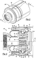
FIG. 1 is a cut-away side view of a joint assembly of the present invention;FIG. 2 is partial perspective view of another joint assembly of the present invention; -
FIG. 3 is a cut-way side view along lines 3-3 ofFIG. 2 ; -
FIG. 4 is a schematic side view of an initial step in the method of securing a shaft and the joint assembly; and -
FIG. 5 is a schematic side view of a step subsequent toFIG. 4 . - It is to be understood that the invention may assume various alternative orientations and step sequences, except where expressly specified to the contrary. It is also to be understood that the specific devices and processes illustrated in the attached drawings, and described in the following specification are simply exemplary embodiments of the inventive concepts defined in the appended claims. Hence, specific dimensions, directions or other physical characteristics relating to the embodiments disclosed are not to be considered as limiting, unless the claims expressly state otherwise.
- Turning now to
Fig. 1 , one embodiment of a constant velocityjoint assembly 10 is depicted.Fig. 1 is for illustrative purposes only; other constant velocity joints including double offset, N+N, Rzeppa, plunging, tripod, undercut free, cross-groove and Weiss may be used with the present invention without limitation. - The
assembly 10 comprises ashaft 12, such as a stub shaft, aninner race 14, anouter race 16, acage 18 andball bearings 20. Theassembly 10 may, in one embodiment, also comprise a boot can insert 22, aboot 24 and adust cap 26. The assembly may also comprise adrive shaft 28, as will be described below. - The
shaft 12 is provided with afirst end 30, afirst end portion 32, asecond end 34, asecond end portion 36 and abody portion 38 located between the first and second ends 30, 34. Thefirst end 30 may have radiused or chamfered corners 40, or the corners 40 may have ninety degree angles. - The
first end portion 32 defines a substantially constantouter diameter 42 of theshaft 12. Thesecond end portion 36 may have an expandingsection 44, formed in a unitary fashion with thebody portion 38. One or morecircumferential grooves 46 may be located in either thefirst end portion 32 or thesecond end portion 36, or both. Theend portions - The expanding
section 44 has anouter surface 48 upon which, or with which, a tube (not shown) may be connected. The tube may be connected mechanically to theouter surface 48 of the expandingsection 44 and/or by welding, friction fitting, crimping, adhesives or combinations of the foregoing. - The
inner race 14 is provided with aninner surface 50, anouter surface 52, afirst end 54 and asecond end 56. Theinner surface 50 of theinner race 14 is secured to thefirst end portion 32 of theshaft 12. Often, thefirst end 54 of theinner race 14 is axially offset from thefirst end 30 of theshaft 12. - The
outer surface 52 of theinner race 14 is provided with a plurality of circumferentially spaced apartgrooves 58. Thegrooves 58 preferably extend from thefirst end 54 of theinner race 14 to thesecond end 56 of theinner race 14. Theouter surface 52 of theinner race 14 may have a curvilinear shape. - Preferably, the
inner surface 50, theouter surface 52, the ends 54, 56 and thegrooves 58 are unitary with one another. - The
cage 18 is provided with afirst end 60, asecond end 62, aninner surface 64 and anouter surface 66. A plurality ofapertures 68 is located in thecage 18 and they extend from theinner surface 64 to theouter surface 66. - The
first end 60 of thecage 18 is shown axially aligned with thefirst end 30 of theshaft 12. Further, thefirst end 60 of thecage 18 extends axially beyond thefirst end 54 of theinner race 14. Thesecond end 62 of thecage 18 extends axially beyond thesecond end 56 of theinner race 14. Theinner surface 64 and theouter surface 66 of thecage 18 may be curvilinear. - Preferably, each of the
ends - The outer race has an
inner surface 70, anouter surface 72, afirst end 74, asecond end 76, afirst body portion 78 and asecond body portion 80. Preferably, each of the foregoing are unitary with one another. Theouter race 70 has an overall cylindrical shape formed by theinner surface 70 and theouter surface 72. - The
first end 74 of theouter race 16 is slightly axially offset from thefirst end 60 of thecage 18 and thefirst end 30 of theshaft 12. Thefirst body portion 78 extends from thefirst end 74 axially inwardly into therace 16. Theinner surface 70 at thefirst body portion 78 comprises a plurality ofgrooves 82 and may be curvilinear. The number ofgrooves 82 is equal to the number ofgrooves 58 on theinner race 14. - The
inner surface 70 of thesecond body portion 80 has a substantiallyconstant diameter portion 84. As such, it forms a cylindrical type extension, or boot can 86, from thefirst body portion 78. The substantiallyconstant diameter portion 84 of theinner surface 70 is preferably parallel with thediameter 42 of theshaft 12 in one embodiment while theassembly 10 is in the orientation depicted inFig. 1 . The substantiallyconstant diameter portion 84 of theinner surface 70 is preferably parallel with thedrive shaft 28 in any orientation of theassembly 10. - One
ball bearing 20 may be located within eachaperture 68 of thecage 18. Eachball bearing 20 preferably rotates and moves along one of thegrooves 82 of theouter race 16 and one of thegrooves 58 in theinner race 14. - The above-described structure permits the
shaft 12 to move with respect to theouter race 16. Thus, in one embodiment, a longitudinal axis 90 of theshaft 12 may be aligned with alongitudinal axis 92 of theouter race 16. In this embodiment, thejoint assembly 10 is a zero articulation angle orientation. Either theouter race 16 may be located at an angle with respect to theshaft 12 or vice versa. However, in another embodiment (not shown), the twoaxes 90, 92 may be at an angle with respect to one another. In the non-depicted embodiment, which is well-known to those skilled in the art, there will be an articulation angle for thejoint assembly 10. - The
inner surface 70 of theouter race 16 defines aninner void 94 in which at least thefirst end 32 portion of theshaft 12, theinner race 14, thecage 18 and theball bearings 20 reside. - The
second end 76 of theouter race 16 may form a ninety degree angle with respect to theinner surface 70 of thesecond body portion 80. Other angles other than ninety degrees are permissible. - The
outer surface 72 of theouter race 16 has a portion located radially outward from the substantiallyconstant diameter portion 84. Adepression 98 in the above-mentioned portion of theouter surface 72 is provided. At least onestep 100 is located directly beside thedepression 98, adjacent thesecond end 76, and extends radially outward therefrom. In the depicted embodiment, twosteps 100 are provided, although any number of steps are permissible. - The
outer surface 72 of theouter race 16 also has a substantially constantouter diameter portion 102 located radially outward from the plurality ofgrooves 82. The constantouter diameter portion 102 may extend from thedepression 98 to thefirst end 74 or, as shown inFig. 1 , arecess 104 for thedust cap 26 andseal 106 may be provided therein. - Preferably, the
recess 104 is dimensioned so that anouter surface 108 of thedust cap 26 provides an overall planar surface with the rest of theouter surface 72 of theouter race 16 at that end of theouter race 16. Theseal 106 may be such as an O-ring and may be located within therecess 104 to seal theouter race 16 with thedust cap 26. Alternatively, a liquid sealant can be applied to thefirst end 74 to secure thedust cap 26 thereto. The O-ring can be omitted when the sealant is utilized. - The
dust cap 26 may extend from theouter surface 72 of theouter race 16, across theball bearing 20, acrossthe.cage 18, across theinner race 14 and across the first end of theshaft 30 so as to provide a substantially impenetrable barrier to dust, debris, moisture and the like. - A
first leg 110 of the boot can insert 22 may be located along the substantiallyconstant diameter portion 84 of theinner surface 70 of theouter race 16. Thefirst leg 110 may be secured to theconstant diameter portion 84 of theouter race 16 by mechanical fasteners, welding, adhesives and/or frictional engagement. Aseal 114 may be located between theouter race 16 and the boot can 22. - A
second leg 116 of the boot can insert 22 extends substantially perpendicularly to thefirst leg 110. Thesecond leg 116 extends parallel to thesecond end 76 of theouter race 16. Thesecond leg 116 may be secured to thesecond end 76 in a similar manner to that of thefirst leg 110 and theouter race 16. - A
first portion 118 of theflexible boot 24 may be located along thefirst leg 110 of the boot can insert 22. In the depicted embodiment, thefirst leg 110 extends substantially entirely along thefirst leg 110 of the boot can insert 22. Theboot 24 may be secured to theinsert 22 such as by friction, adhesive, vulcanization, mechanical fasteners and the like. - In the depicted embodiment, the
boot 24 is provided with an outwardly extendingcurved portion 120. Theboot 24, however, is not limited to this configuration. Instead, theboot 24 may be provided with an S-shape or any other configuration such that dirt, debris and moisture are kept out of theassembly 10. - A
second portion 122 of theboot 24 may be located along, or adjacent, the substantiallyconstant diameter portion 42 of theshaft 12. Thesecond portion 122 may be secured to theshaft 12 such as by friction, adhesive, mechanical fasteners and the like. In the depicted embodiment, acollar 124 may be provided about theshaft 12. Thecollar 124 may extend to theinner surface 50 of theinner race 14 where aleg 126 extends radially into theinner race 14. Thesecond portion 122 of theboot 24 may be attached to thecollar 124 by vulcanization, adhesives, mechanical fasteners or the like. - The
second body portion 80 of theouter race 16 advantageously functions to shroud and protect theboot 24 from any damage. Further, thesecond body portion 80 of theouter race 16 facilitates heat transfer out of thejoint assembly 10 during operation of theassembly 10 via thedrive shaft 28. This permits a greater power density to be used with a magnetic pulse welding process verses the traditional wire welded or magnetic arc welded assemblies. Additionally, the heat transfer should be better than friction welded assemblies because the magnetic pulse welding weld has a closer proximity to the heat generating joint running surfaces. - Yet another embodiment of the present invention is depicted in
Figs. 2 and 3 . It may be readily appreciated that thejoint assembly 128 depicted inFigs. 2 and 3 has many of the same components as discussed above and depicted inFig. 1 . The same reference numbers have been used where there is identity between the components ofFigs. 1 and2 and 3 . -
Figs. 2 and 3 additionally depict atube 130 having afirst end portion 132 and asecond end portion 134. Thefirst portion 132 has a substantiallyconstant diameter portion 136. Thesecond end portion 134 has a plurality of axially extendingprongs 138. Theprongs 138 extend along internal splines 140 of theinner race 14 andbarbs 144 on theprongs 138 engage with thefirst end 54 of theinner race 14. - The
first leg 110 of the boot can insert 22 is parallel to the substantiallyconstant diameter portion 136 of thetube 130 when the joint articulation angle is zero, as shown in the Figures. Additionally, thesecond end 62 of thecage 18 is permitted to axially extend into the boot can insert 22. In the depicted embodiment, thesecond end 56 of theinner race 14 terminates at the end ofouter race grooves 82. - The
first portion 118 of theflexible boot 24 may be located along thefirst leg 110 of the boot can insert 22 as previously discussed. Thesecond portion 122 of theboot 24 may be located along the substantiallyconstant diameter portion 136 of thetube 130. Thesecond portion 122 may be secured to thetube 130 such as by friction, adhesive, vulcanization, mechanical fasteners and the like. - The steps of securing the
drive shaft 28 to either constant velocityjoint assembly outer race 16 within adrive shaft 28 having ahollow end portion 146, as shown inFig. 4 . Theouter race 16 is located with theend portion 146 until theend portion 146 extends at least to thedepression 98 in theouter surface 72. Preferably, theend portion 146 is sufficiently located over theouter surface 72 so that it can be subsequently located within thedepression 98 andsteps 100 of theouter surface 72 of theouter race 16. - The
drive shaft 28 is preferably metallic and may be such as aluminum, and in particular, strong aluminum alloys, such as 6061T aluminum alloy. - An
inductor 148 is located axially relative to theouter race 16 and thedrive shaft 28. Agap 150 may exist between theouter surface 146 of theshaft 28 and theinductor 148. Thegap 150 may be a constant dimension or it may vary. - The
inductor 148 is energized to magnetically pulse weld theshaft 28 and theouter race 16 together. Theinductor 148 and the magnetic pulse welding technique are depicted and described inU.S. Patent Nos. 7015435 ,6891137 ,6703594 ,6531688 ,6379254 ,5981921 ,7026585 ,4,129,846 andRE41, 101 , which are all incorporated by reference in their entireties. These patents are owned by the assignee of the present application. - The
inductor 148 includes aninductor coil 154. Thecoil 154 may be such as a high strength single-turn coil or a plurality of generally close packed, but spaced apart, circular or annular electrical conductor strips. Insulators (not shown) may be located between the strips. - The
inductor 148 includesleads 156 or terminals tohigh voltage capacitors 158. Thecapacitors 158 are connected to a source ofelectrical power 160 via acharging circuit 162. The current required for successfully welding ashaft 28 to theouter race 16 is on the order of at least several hundred thousand amps and possibly as high as one million amps or more. Therefore, the circuit, through which the current is discharged, must be suitable for conducting a current of great magnitude. - The
discharge circuit 164 includes a discharge switch (not shown) which when activated allows the capacitors to discharge and supply an energy surge to theinductor 148. Theinductor 148 creates a strong magnetic field that exerts a force against theouter surface 166 of theshaft 28. The discharge switch, therefore, must also suitable for conducting the high currents in the circuit. - The effect of the intense, momentary magnetic field on the
metallic shaft 28 is to create an extremely powerful force which repels theshaft 28 radially, inward from theinductor 148. The magnetic field created by the pulse of current through theinductor 148 creates strong reactive eddy currents in theshaft 28. These eddy currents create opposing magnetic fields which result in inwardly directed forces on theshaft 28. These forces cause theshaft 28 to collapse about theouter race 16 with such impact that theshaft 28 is welded to theouter race 16. The velocity of theshaft 28 when it comes into contact withouter race 16 is preferably at least 300 meters per second and more preferably within the range from about 300 to 400 meters per second. - The
end portion 146 is welded to the substantially constant diameter portion of theouter race 102, thedepression 98 and/or thestep 100. It may be appreciated that theend portion 146 may be welded to one or more of these features of the outer race. - In accordance with the provisions of the patent statutes, the present invention has been described in what is considered to represent its preferred embodiments. However, it should be noted that the invention can be practiced otherwise than as specifically illustrated and described without departing from the scope of the appended claims.
Claims (5)
- A constant velocity joint assembly (10), comprising:a shaft (12), an inner race (14), an unitary outer race (16), a cage (18) and ball bearings (20), whereinthe shaft (12) has an outer surface, and wherein the shaft comprises a first end (30), a first end portion (32), a second end (34), a second end portion (36), wherein the first end portion (32) defines a substantially constant outer diameter portion (42) of the shaft (12),the unitary outer race (16) has an inner surface (70) with a first portion (78) and a second portion (80) directly abutting said first portion (78), wherein said second portion (80) is located radially outward from said substantially constant outer diameter portion (42) of said shaft (12), wherein said first portion (78) defines a plurality of grooves (82) and said second portion (80) has an inner portion, and wherein the inner surface (70) of the outer race (16) defines an inner void (94) in which at least the first end portion (32) of the shaft (12), the inner race (14), the cage (18) and the ball bearings (20) reside and whereina boot can insert (22) is located along said second portion (80) of said outer race (16) anda boot (24) has a first portion (118) located along said boot can insert (22) and a second portion (122) located along said shaft (12) characterized in that the second portion (122) of the boot (24) is located and connected to the shaft (12) along the substantially constant diameter portion (42) defined by the first end portion (32) of the shaft (12).
- The assembly (10) according to claim 1, characterized in that the inner portion of the second portion (122) is parallel with said outer diameter of said shaft (12) at zero articulation angle.
- The assembly (10) of claim 1 or 2, wherein an outer surface (72) of said outer race (16) is comprised of a depression (98) in said outer surface, said depression (98) transitioning directly to at least one radially extending step (100).
- The assembly (10) of claim 3, characterized in that the inner race (14) has an inner surface (50) in contact with said shaft (12) and an outer surface (52) having a plurality of grooves (58) matched with said grooves (82) of said outer race, said inner race (14) having a first end (54) and a second end (56), said ends (54, 56) located axially within said grooves (82) of said outer race (16).
- The assembly (10) of claim 4, wherein the cage has a first end (60) radially aligned with a first end (30) of said shaft (12), and a second end (62) extending axially beyond said second end (56) of said inner race (14) and said plurality of grooves (82) on said outer race (16).
Applications Claiming Priority (2)
| Application Number | Priority Date | Filing Date | Title |
|---|---|---|---|
| US12/804,380 US8414406B2 (en) | 2010-07-19 | 2010-07-19 | Constant velocity joint assembly and method of securing a shaft to the assembly |
| PCT/US2011/001065 WO2012011935A1 (en) | 2010-07-19 | 2011-06-10 | Constant velocity joint assembly and method of securing a shaft to the assembly |
Publications (2)
| Publication Number | Publication Date |
|---|---|
| EP2596259A1 EP2596259A1 (en) | 2013-05-29 |
| EP2596259B1 true EP2596259B1 (en) | 2017-03-29 |
Family
ID=44303508
Family Applications (1)
| Application Number | Title | Priority Date | Filing Date |
|---|---|---|---|
| EP11727341.7A Not-in-force EP2596259B1 (en) | 2010-07-19 | 2011-06-10 | Constant velocity joint assembly and method of securing a shaft to the assembly |
Country Status (10)
| Country | Link |
|---|---|
| US (2) | US8414406B2 (en) |
| EP (1) | EP2596259B1 (en) |
| JP (1) | JP5565716B2 (en) |
| KR (1) | KR101871736B1 (en) |
| CN (2) | CN104948598B (en) |
| AU (1) | AU2011280231B2 (en) |
| BR (1) | BR112013000229A2 (en) |
| ES (1) | ES2625500T3 (en) |
| MX (1) | MX2013000704A (en) |
| WO (1) | WO2012011935A1 (en) |
Families Citing this family (12)
| Publication number | Priority date | Publication date | Assignee | Title |
|---|---|---|---|---|
| KR101869073B1 (en) * | 2011-09-21 | 2018-06-20 | 지케이엔 드라이브라인 노쓰 아메리카, 인코포레이티드 | External rolling diaphragm overmoulded high speed constant velocity joint boot |
| US8734045B1 (en) * | 2012-11-16 | 2014-05-27 | Dana Automotive Systems Group, Llc | Inner race and boot sleeve |
| US9097287B2 (en) | 2012-11-16 | 2015-08-04 | Dana Automotive Systems Group, Llc | Inner race and boot sleeve |
| US8784220B1 (en) * | 2013-03-13 | 2014-07-22 | NTN Bearing Coporation of America | Plug-in CVJ assembly |
| KR101704327B1 (en) * | 2013-12-13 | 2017-02-07 | 데이나 오토모티브 시스템즈 그룹 엘엘씨 | Inner race and boot sleeve |
| CN103817424B (en) * | 2014-01-23 | 2017-08-04 | 浙江日丰机械股份有限公司 | A kind of belt pulley friction welding device |
| DE102014110602A1 (en) | 2014-02-28 | 2015-09-03 | Johnson Electric Germany GmbH & Co. KG | Device with a moving component |
| EP3173647B1 (en) * | 2014-07-23 | 2020-10-14 | NTN Corporation | Constant velocity universal joint |
| DE102016007495B4 (en) * | 2016-06-21 | 2018-10-11 | Ifa-Technologies Gmbh | Constant velocity joint with integral inner joint part and method for producing such a constant velocity joint |
| US11242897B2 (en) * | 2016-11-01 | 2022-02-08 | Dana Automotive Systems Group, Llc | Coupling assembly having angled fastener holes |
| KR102042776B1 (en) * | 2018-02-08 | 2019-11-08 | 주식회사 건화이엔지 | boot |
| CN113843492B (en) * | 2021-11-11 | 2023-05-09 | 重庆市光学机械研究所 | A fuel element plug body welding method |
Family Cites Families (33)
| Publication number | Priority date | Publication date | Assignee | Title |
|---|---|---|---|---|
| US2432803A (en) | 1944-07-27 | 1947-12-16 | Bendix Aviat Corp | Sealing means for universal joints |
| GB1150954A (en) | 1966-09-16 | 1969-05-07 | Birfield Eng Ltd | Improvements in or relating to Flexible Seals |
| FR1579435A (en) * | 1967-09-28 | 1969-08-22 | ||
| US4129846A (en) | 1975-08-13 | 1978-12-12 | Yablochnikov B | Inductor for magnetic pulse working of tubular metal articles |
| DE2740226C3 (en) * | 1977-09-07 | 1980-10-30 | Uni-Cardan Ag, 5200 Siegburg | Constant velocity swivel |
| JPS5639324A (en) * | 1979-09-10 | 1981-04-15 | Nippon Light Metal Co Ltd | Manufacture of fixed speed universal joint device |
| DE3009639C2 (en) | 1980-03-13 | 1983-01-27 | Löhr & Bromkamp GmbH, 6050 Offenbach | seal |
| DE3035884A1 (en) | 1980-09-24 | 1982-04-08 | Uni-Cardan Ag, 5200 Siegburg | SEALING ARRANGEMENT |
| DE3123573C2 (en) | 1981-06-13 | 1983-03-24 | Uni-Cardan Ag, 5200 Siegburg | "Seal arrangement" |
| US4813808A (en) * | 1983-08-19 | 1989-03-21 | Gkn Automotive Components Inc. | Axial retaining member and method for interconnecting male and female splined members |
| CA2016894A1 (en) * | 1989-07-25 | 1991-01-25 | Werner Krude | Constant velocity universal joint |
| US6379254B1 (en) | 1997-06-20 | 2002-04-30 | Spicer Driveshaft, Inc. | End fitting adapted to be secured to driveshaft tube by electromagnetic pulse welding |
| US5981921A (en) * | 1997-06-20 | 1999-11-09 | Dana Corporation | Method of magnetic pulse welding an end fitting to a driveshaft tube of a vehicular driveshaft |
| US5807180A (en) * | 1997-08-28 | 1998-09-15 | Dana Corporation | Constant velocity universal joint shaft and inner race combination |
| JP2001304285A (en) | 2000-04-20 | 2001-10-31 | Ntn Corp | Constant velocity universal joint and bearing system for wheel using it |
| US6264568B1 (en) | 2000-08-09 | 2001-07-24 | Gkn Automotive, Inc. | Boot arrangement for a constant velocity joint |
| JP2002070879A (en) * | 2000-08-25 | 2002-03-08 | Koyo Seiko Co Ltd | Bearing device for vehicle |
| JP4047564B2 (en) * | 2001-09-18 | 2008-02-13 | 株式会社日立製作所 | Universal joint and propeller shaft using the same |
| US6910617B2 (en) * | 2002-03-06 | 2005-06-28 | Torque-Traction Technologies, Inc. | Method for securing a yoke to a tube using magnetic pulse welding techniques |
| DE10212898B4 (en) | 2002-03-22 | 2004-03-04 | GKN Löbro GmbH | Rolling bellows and rolling bellows arrangement |
| DE10237216B4 (en) | 2002-08-14 | 2004-12-02 | Gkn Driveline Deutschland Gmbh | Method for applying a balancing mass to a rotating body to be balanced |
| US6926612B2 (en) | 2003-09-04 | 2005-08-09 | Gkn Driveline North America, Inc. | Joint assembly and sealing boot |
| IL163974A0 (en) | 2003-09-10 | 2005-12-18 | Dana Corp | Method for monitoring the performance of a magnetic pulse forming or welding process |
| DE102004034772B4 (en) | 2004-01-02 | 2011-03-03 | Gkn Driveline International Gmbh | Rolling bellows with stiffeners |
| US7040992B2 (en) * | 2004-01-31 | 2006-05-09 | Gkn Driveline North America, Inc. | Boltless retention system for a constant velocity joint |
| CN2733084Y (en) * | 2004-09-03 | 2005-10-12 | 万向钱潮股份有限公司 | Universal joint with self-locking dustproof sealing structure |
| JP2007056995A (en) | 2005-08-24 | 2007-03-08 | Ntn Corp | Flexible boot for constant velocity universal joint |
| US7347784B2 (en) | 2005-09-20 | 2008-03-25 | Torque-Traction Technologies Llc | Driveshaft assembly and method of manufacturing same |
| CN101287920B (en) | 2005-10-11 | 2012-07-04 | Gkn动力传动系统北美有限公司 | Direct torque flow connection with optimized ratios in the attachment method |
| CN101351654B (en) * | 2006-01-03 | 2013-07-17 | Gkn动力传动系统北美有限公司 | Connected direct torquemoment stream constant velocity universal joint with clamping head |
| US20070173337A1 (en) | 2006-01-26 | 2007-07-26 | Hans Wormsbaecher | Rolling boot assembly |
| US7677984B2 (en) | 2006-08-28 | 2010-03-16 | Gkn Driveline North America, Inc. | Protected connection interface for direct torque flow constant velocity joint and method thereof |
| DE112007003077B4 (en) * | 2006-12-18 | 2018-11-08 | Gkn Driveline North America, Inc. | Grease cover molding with retention feature |
-
2010
- 2010-07-19 US US12/804,380 patent/US8414406B2/en not_active Expired - Fee Related
-
2011
- 2011-06-10 CN CN201510216011.8A patent/CN104948598B/en not_active Expired - Fee Related
- 2011-06-10 MX MX2013000704A patent/MX2013000704A/en not_active Application Discontinuation
- 2011-06-10 WO PCT/US2011/001065 patent/WO2012011935A1/en not_active Ceased
- 2011-06-10 JP JP2013520697A patent/JP5565716B2/en not_active Expired - Fee Related
- 2011-06-10 CN CN201180035287.6A patent/CN103003585B/en not_active Expired - Fee Related
- 2011-06-10 ES ES11727341.7T patent/ES2625500T3/en active Active
- 2011-06-10 KR KR1020137003862A patent/KR101871736B1/en not_active Expired - Fee Related
- 2011-06-10 AU AU2011280231A patent/AU2011280231B2/en not_active Ceased
- 2011-06-10 EP EP11727341.7A patent/EP2596259B1/en not_active Not-in-force
- 2011-06-10 BR BR112013000229A patent/BR112013000229A2/en not_active Application Discontinuation
-
2013
- 2013-01-22 US US13/747,136 patent/US8584341B2/en not_active Expired - Fee Related
Non-Patent Citations (1)
| Title |
|---|
| None * |
Also Published As
| Publication number | Publication date |
|---|---|
| US8414406B2 (en) | 2013-04-09 |
| US8584341B2 (en) | 2013-11-19 |
| BR112013000229A2 (en) | 2016-05-31 |
| CN104948598A (en) | 2015-09-30 |
| CN103003585A (en) | 2013-03-27 |
| KR101871736B1 (en) | 2018-06-27 |
| AU2011280231B2 (en) | 2014-03-27 |
| US20130134152A1 (en) | 2013-05-30 |
| CN103003585B (en) | 2017-07-21 |
| CN104948598B (en) | 2018-05-18 |
| EP2596259A1 (en) | 2013-05-29 |
| US20120015750A1 (en) | 2012-01-19 |
| AU2011280231A1 (en) | 2013-01-31 |
| JP5565716B2 (en) | 2014-08-06 |
| WO2012011935A1 (en) | 2012-01-26 |
| KR20130141439A (en) | 2013-12-26 |
| JP2013531210A (en) | 2013-08-01 |
| ES2625500T3 (en) | 2017-07-19 |
| MX2013000704A (en) | 2013-03-08 |
Similar Documents
| Publication | Publication Date | Title |
|---|---|---|
| US8584341B2 (en) | Method of securing a shaft to a constant velocity joint | |
| US7507161B2 (en) | Propshaft with constant velocity joint attachment | |
| US8449399B2 (en) | Joint assembly with centering flange | |
| EP1375943B1 (en) | Rolling ball slip joint formed from two tubular members | |
| EP2172666B1 (en) | Joint for steering | |
| JP2014526664A (en) | High angle constant velocity joints and boots | |
| EP1934494A1 (en) | Direct torque flow connection with optimized ratios in attachment methods | |
| US9488231B2 (en) | Cooling assembly and method for providing cooling air flow in region of constant velocity joint | |
| US20100069164A1 (en) | Fixed type constant velocity universal joint | |
| US20120151907A1 (en) | Flanged impeller hub | |
| KR102889063B1 (en) | Wheel bearing assembly | |
| US10125824B2 (en) | Multi-piece driveshaft assembly | |
| US11420470B2 (en) | Wheel bearing | |
| JP2002213429A (en) | Propeller shaft | |
| JP2008002581A (en) | Bearing unit for drive wheel | |
| JP2011112118A (en) | Boot band for constant velocity universal joint, constant velocity universal joint using the same, and method of manufacturing the same | |
| WO2018020991A1 (en) | Constant-velocity universal joint |
Legal Events
| Date | Code | Title | Description |
|---|---|---|---|
| PUAI | Public reference made under article 153(3) epc to a published international application that has entered the european phase |
Free format text: ORIGINAL CODE: 0009012 |
|
| 17P | Request for examination filed |
Effective date: 20130111 |
|
| AK | Designated contracting states |
Kind code of ref document: A1 Designated state(s): AL AT BE BG CH CY CZ DE DK EE ES FI FR GB GR HR HU IE IS IT LI LT LU LV MC MK MT NL NO PL PT RO RS SE SI SK SM TR |
|
| DAX | Request for extension of the european patent (deleted) | ||
| 17Q | First examination report despatched |
Effective date: 20150113 |
|
| GRAP | Despatch of communication of intention to grant a patent |
Free format text: ORIGINAL CODE: EPIDOSNIGR1 |
|
| INTG | Intention to grant announced |
Effective date: 20161025 |
|
| GRAS | Grant fee paid |
Free format text: ORIGINAL CODE: EPIDOSNIGR3 |
|
| GRAA | (expected) grant |
Free format text: ORIGINAL CODE: 0009210 |
|
| AK | Designated contracting states |
Kind code of ref document: B1 Designated state(s): AL AT BE BG CH CY CZ DE DK EE ES FI FR GB GR HR HU IE IS IT LI LT LU LV MC MK MT NL NO PL PT RO RS SE SI SK SM TR |
|
| REG | Reference to a national code |
Ref country code: GB Ref legal event code: FG4D |
|
| REG | Reference to a national code |
Ref country code: CH Ref legal event code: EP |
|
| REG | Reference to a national code |
Ref country code: AT Ref legal event code: REF Ref document number: 880075 Country of ref document: AT Kind code of ref document: T Effective date: 20170415 |
|
| REG | Reference to a national code |
Ref country code: IE Ref legal event code: FG4D |
|
| REG | Reference to a national code |
Ref country code: DE Ref legal event code: R096 Ref document number: 602011036434 Country of ref document: DE |
|
| REG | Reference to a national code |
Ref country code: ES Ref legal event code: FG2A Ref document number: 2625500 Country of ref document: ES Kind code of ref document: T3 Effective date: 20170719 |
|
| PG25 | Lapsed in a contracting state [announced via postgrant information from national office to epo] |
Ref country code: HR Free format text: LAPSE BECAUSE OF FAILURE TO SUBMIT A TRANSLATION OF THE DESCRIPTION OR TO PAY THE FEE WITHIN THE PRESCRIBED TIME-LIMIT Effective date: 20170329 Ref country code: NO Free format text: LAPSE BECAUSE OF FAILURE TO SUBMIT A TRANSLATION OF THE DESCRIPTION OR TO PAY THE FEE WITHIN THE PRESCRIBED TIME-LIMIT Effective date: 20170629 Ref country code: GR Free format text: LAPSE BECAUSE OF FAILURE TO SUBMIT A TRANSLATION OF THE DESCRIPTION OR TO PAY THE FEE WITHIN THE PRESCRIBED TIME-LIMIT Effective date: 20170630 Ref country code: LT Free format text: LAPSE BECAUSE OF FAILURE TO SUBMIT A TRANSLATION OF THE DESCRIPTION OR TO PAY THE FEE WITHIN THE PRESCRIBED TIME-LIMIT Effective date: 20170329 Ref country code: FI Free format text: LAPSE BECAUSE OF FAILURE TO SUBMIT A TRANSLATION OF THE DESCRIPTION OR TO PAY THE FEE WITHIN THE PRESCRIBED TIME-LIMIT Effective date: 20170329 |
|
| REG | Reference to a national code |
Ref country code: NL Ref legal event code: MP Effective date: 20170329 |
|
| REG | Reference to a national code |
Ref country code: AT Ref legal event code: MK05 Ref document number: 880075 Country of ref document: AT Kind code of ref document: T Effective date: 20170329 |
|
| PG25 | Lapsed in a contracting state [announced via postgrant information from national office to epo] |
Ref country code: SE Free format text: LAPSE BECAUSE OF FAILURE TO SUBMIT A TRANSLATION OF THE DESCRIPTION OR TO PAY THE FEE WITHIN THE PRESCRIBED TIME-LIMIT Effective date: 20170329 Ref country code: LV Free format text: LAPSE BECAUSE OF FAILURE TO SUBMIT A TRANSLATION OF THE DESCRIPTION OR TO PAY THE FEE WITHIN THE PRESCRIBED TIME-LIMIT Effective date: 20170329 Ref country code: RS Free format text: LAPSE BECAUSE OF FAILURE TO SUBMIT A TRANSLATION OF THE DESCRIPTION OR TO PAY THE FEE WITHIN THE PRESCRIBED TIME-LIMIT Effective date: 20170329 Ref country code: BG Free format text: LAPSE BECAUSE OF FAILURE TO SUBMIT A TRANSLATION OF THE DESCRIPTION OR TO PAY THE FEE WITHIN THE PRESCRIBED TIME-LIMIT Effective date: 20170629 |
|
| PG25 | Lapsed in a contracting state [announced via postgrant information from national office to epo] |
Ref country code: NL Free format text: LAPSE BECAUSE OF FAILURE TO SUBMIT A TRANSLATION OF THE DESCRIPTION OR TO PAY THE FEE WITHIN THE PRESCRIBED TIME-LIMIT Effective date: 20170329 |
|
| PG25 | Lapsed in a contracting state [announced via postgrant information from national office to epo] |
Ref country code: EE Free format text: LAPSE BECAUSE OF FAILURE TO SUBMIT A TRANSLATION OF THE DESCRIPTION OR TO PAY THE FEE WITHIN THE PRESCRIBED TIME-LIMIT Effective date: 20170329 Ref country code: CZ Free format text: LAPSE BECAUSE OF FAILURE TO SUBMIT A TRANSLATION OF THE DESCRIPTION OR TO PAY THE FEE WITHIN THE PRESCRIBED TIME-LIMIT Effective date: 20170329 Ref country code: AT Free format text: LAPSE BECAUSE OF FAILURE TO SUBMIT A TRANSLATION OF THE DESCRIPTION OR TO PAY THE FEE WITHIN THE PRESCRIBED TIME-LIMIT Effective date: 20170329 Ref country code: IT Free format text: LAPSE BECAUSE OF FAILURE TO SUBMIT A TRANSLATION OF THE DESCRIPTION OR TO PAY THE FEE WITHIN THE PRESCRIBED TIME-LIMIT Effective date: 20170329 Ref country code: RO Free format text: LAPSE BECAUSE OF FAILURE TO SUBMIT A TRANSLATION OF THE DESCRIPTION OR TO PAY THE FEE WITHIN THE PRESCRIBED TIME-LIMIT Effective date: 20170329 Ref country code: SK Free format text: LAPSE BECAUSE OF FAILURE TO SUBMIT A TRANSLATION OF THE DESCRIPTION OR TO PAY THE FEE WITHIN THE PRESCRIBED TIME-LIMIT Effective date: 20170329 |
|
| PG25 | Lapsed in a contracting state [announced via postgrant information from national office to epo] |
Ref country code: IS Free format text: LAPSE BECAUSE OF FAILURE TO SUBMIT A TRANSLATION OF THE DESCRIPTION OR TO PAY THE FEE WITHIN THE PRESCRIBED TIME-LIMIT Effective date: 20170729 Ref country code: PT Free format text: LAPSE BECAUSE OF FAILURE TO SUBMIT A TRANSLATION OF THE DESCRIPTION OR TO PAY THE FEE WITHIN THE PRESCRIBED TIME-LIMIT Effective date: 20170731 Ref country code: SM Free format text: LAPSE BECAUSE OF FAILURE TO SUBMIT A TRANSLATION OF THE DESCRIPTION OR TO PAY THE FEE WITHIN THE PRESCRIBED TIME-LIMIT Effective date: 20170329 Ref country code: PL Free format text: LAPSE BECAUSE OF FAILURE TO SUBMIT A TRANSLATION OF THE DESCRIPTION OR TO PAY THE FEE WITHIN THE PRESCRIBED TIME-LIMIT Effective date: 20170329 |
|
| REG | Reference to a national code |
Ref country code: DE Ref legal event code: R097 Ref document number: 602011036434 Country of ref document: DE |
|
| PG25 | Lapsed in a contracting state [announced via postgrant information from national office to epo] |
Ref country code: DK Free format text: LAPSE BECAUSE OF FAILURE TO SUBMIT A TRANSLATION OF THE DESCRIPTION OR TO PAY THE FEE WITHIN THE PRESCRIBED TIME-LIMIT Effective date: 20170329 Ref country code: MC Free format text: LAPSE BECAUSE OF FAILURE TO SUBMIT A TRANSLATION OF THE DESCRIPTION OR TO PAY THE FEE WITHIN THE PRESCRIBED TIME-LIMIT Effective date: 20170329 |
|
| REG | Reference to a national code |
Ref country code: CH Ref legal event code: PL |
|
| PLBE | No opposition filed within time limit |
Free format text: ORIGINAL CODE: 0009261 |
|
| STAA | Information on the status of an ep patent application or granted ep patent |
Free format text: STATUS: NO OPPOSITION FILED WITHIN TIME LIMIT |
|
| 26N | No opposition filed |
Effective date: 20180103 |
|
| REG | Reference to a national code |
Ref country code: IE Ref legal event code: MM4A |
|
| REG | Reference to a national code |
Ref country code: FR Ref legal event code: ST Effective date: 20180228 |
|
| PG25 | Lapsed in a contracting state [announced via postgrant information from national office to epo] |
Ref country code: CH Free format text: LAPSE BECAUSE OF NON-PAYMENT OF DUE FEES Effective date: 20170630 Ref country code: LU Free format text: LAPSE BECAUSE OF NON-PAYMENT OF DUE FEES Effective date: 20170610 Ref country code: LI Free format text: LAPSE BECAUSE OF NON-PAYMENT OF DUE FEES Effective date: 20170630 Ref country code: IE Free format text: LAPSE BECAUSE OF NON-PAYMENT OF DUE FEES Effective date: 20170610 |
|
| PG25 | Lapsed in a contracting state [announced via postgrant information from national office to epo] |
Ref country code: SI Free format text: LAPSE BECAUSE OF FAILURE TO SUBMIT A TRANSLATION OF THE DESCRIPTION OR TO PAY THE FEE WITHIN THE PRESCRIBED TIME-LIMIT Effective date: 20170329 Ref country code: FR Free format text: LAPSE BECAUSE OF NON-PAYMENT OF DUE FEES Effective date: 20170630 |
|
| REG | Reference to a national code |
Ref country code: BE Ref legal event code: MM Effective date: 20170630 |
|
| PG25 | Lapsed in a contracting state [announced via postgrant information from national office to epo] |
Ref country code: BE Free format text: LAPSE BECAUSE OF NON-PAYMENT OF DUE FEES Effective date: 20170630 |
|
| PG25 | Lapsed in a contracting state [announced via postgrant information from national office to epo] |
Ref country code: MT Free format text: LAPSE BECAUSE OF NON-PAYMENT OF DUE FEES Effective date: 20170610 |
|
| PGFP | Annual fee paid to national office [announced via postgrant information from national office to epo] |
Ref country code: SE Payment date: 20180910 Year of fee payment: 9 |
|
| PG25 | Lapsed in a contracting state [announced via postgrant information from national office to epo] |
Ref country code: HU Free format text: LAPSE BECAUSE OF FAILURE TO SUBMIT A TRANSLATION OF THE DESCRIPTION OR TO PAY THE FEE WITHIN THE PRESCRIBED TIME-LIMIT; INVALID AB INITIO Effective date: 20110610 |
|
| PG25 | Lapsed in a contracting state [announced via postgrant information from national office to epo] |
Ref country code: CY Free format text: LAPSE BECAUSE OF NON-PAYMENT OF DUE FEES Effective date: 20170329 |
|
| PG25 | Lapsed in a contracting state [announced via postgrant information from national office to epo] |
Ref country code: MK Free format text: LAPSE BECAUSE OF FAILURE TO SUBMIT A TRANSLATION OF THE DESCRIPTION OR TO PAY THE FEE WITHIN THE PRESCRIBED TIME-LIMIT Effective date: 20170329 |
|
| PG25 | Lapsed in a contracting state [announced via postgrant information from national office to epo] |
Ref country code: TR Free format text: LAPSE BECAUSE OF FAILURE TO SUBMIT A TRANSLATION OF THE DESCRIPTION OR TO PAY THE FEE WITHIN THE PRESCRIBED TIME-LIMIT Effective date: 20170329 |
|
| PG25 | Lapsed in a contracting state [announced via postgrant information from national office to epo] |
Ref country code: AL Free format text: LAPSE BECAUSE OF FAILURE TO SUBMIT A TRANSLATION OF THE DESCRIPTION OR TO PAY THE FEE WITHIN THE PRESCRIBED TIME-LIMIT Effective date: 20170329 |
|
| PGFP | Annual fee paid to national office [announced via postgrant information from national office to epo] |
Ref country code: GB Payment date: 20200629 Year of fee payment: 10 |
|
| REG | Reference to a national code |
Ref country code: ES Ref legal event code: FD2A Effective date: 20201027 |
|
| PG25 | Lapsed in a contracting state [announced via postgrant information from national office to epo] |
Ref country code: ES Free format text: LAPSE BECAUSE OF NON-PAYMENT OF DUE FEES Effective date: 20190611 |
|
| GBPC | Gb: european patent ceased through non-payment of renewal fee |
Effective date: 20210610 |
|
| PG25 | Lapsed in a contracting state [announced via postgrant information from national office to epo] |
Ref country code: GB Free format text: LAPSE BECAUSE OF NON-PAYMENT OF DUE FEES Effective date: 20210610 |
|
| P01 | Opt-out of the competence of the unified patent court (upc) registered |
Effective date: 20230525 |
|
| PGFP | Annual fee paid to national office [announced via postgrant information from national office to epo] |
Ref country code: DE Payment date: 20230523 Year of fee payment: 13 |
|
| REG | Reference to a national code |
Ref country code: DE Ref legal event code: R119 Ref document number: 602011036434 Country of ref document: DE |
|
| PG25 | Lapsed in a contracting state [announced via postgrant information from national office to epo] |
Ref country code: DE Free format text: LAPSE BECAUSE OF NON-PAYMENT OF DUE FEES Effective date: 20250101 |