EP2595862B1 - Electromagnetic and/or vacuum crawler assembly system for moving and fixing a working tools on arcuate surface like a fuselage of an airplane - Google Patents
Electromagnetic and/or vacuum crawler assembly system for moving and fixing a working tools on arcuate surface like a fuselage of an airplane Download PDFInfo
- Publication number
- EP2595862B1 EP2595862B1 EP11733725.3A EP11733725A EP2595862B1 EP 2595862 B1 EP2595862 B1 EP 2595862B1 EP 11733725 A EP11733725 A EP 11733725A EP 2595862 B1 EP2595862 B1 EP 2595862B1
- Authority
- EP
- European Patent Office
- Prior art keywords
- frame
- suction cups
- workpiece
- vacuum
- legs
- Prior art date
- Legal status (The legal status is an assumption and is not a legal conclusion. Google has not performed a legal analysis and makes no representation as to the accuracy of the status listed.)
- Active
Links
- 238000000034 method Methods 0.000 claims description 62
- 239000012636 effector Substances 0.000 claims description 52
- 239000000696 magnetic material Substances 0.000 claims description 7
- 238000004519 manufacturing process Methods 0.000 description 33
- 230000008569 process Effects 0.000 description 33
- 238000012423 maintenance Methods 0.000 description 5
- 230000010354 integration Effects 0.000 description 4
- 239000000565 sealant Substances 0.000 description 4
- 238000010586 diagram Methods 0.000 description 3
- 238000005553 drilling Methods 0.000 description 3
- 230000004048 modification Effects 0.000 description 3
- 238000012986 modification Methods 0.000 description 3
- 238000012545 processing Methods 0.000 description 3
- 238000013461 design Methods 0.000 description 2
- 239000000853 adhesive Substances 0.000 description 1
- 230000001070 adhesive effect Effects 0.000 description 1
- 230000007613 environmental effect Effects 0.000 description 1
- 238000007689 inspection Methods 0.000 description 1
- 238000009434 installation Methods 0.000 description 1
- 239000000463 material Substances 0.000 description 1
- 230000007246 mechanism Effects 0.000 description 1
- 230000008520 organization Effects 0.000 description 1
- 238000003825 pressing Methods 0.000 description 1
- 230000009467 reduction Effects 0.000 description 1
- 238000009419 refurbishment Methods 0.000 description 1
- 238000013519 translation Methods 0.000 description 1
Images


Classifications
-
- B—PERFORMING OPERATIONS; TRANSPORTING
- B23—MACHINE TOOLS; METAL-WORKING NOT OTHERWISE PROVIDED FOR
- B23Q—DETAILS, COMPONENTS, OR ACCESSORIES FOR MACHINE TOOLS, e.g. ARRANGEMENTS FOR COPYING OR CONTROLLING; MACHINE TOOLS IN GENERAL CHARACTERISED BY THE CONSTRUCTION OF PARTICULAR DETAILS OR COMPONENTS; COMBINATIONS OR ASSOCIATIONS OF METAL-WORKING MACHINES, NOT DIRECTED TO A PARTICULAR RESULT
- B23Q9/00—Arrangements for supporting or guiding portable metal-working machines or apparatus
- B23Q9/02—Arrangements for supporting or guiding portable metal-working machines or apparatus for securing machines or apparatus to workpieces, or other parts, of particular shape, e.g. to beams of particular cross-section
-
- B—PERFORMING OPERATIONS; TRANSPORTING
- B23—MACHINE TOOLS; METAL-WORKING NOT OTHERWISE PROVIDED FOR
- B23Q—DETAILS, COMPONENTS, OR ACCESSORIES FOR MACHINE TOOLS, e.g. ARRANGEMENTS FOR COPYING OR CONTROLLING; MACHINE TOOLS IN GENERAL CHARACTERISED BY THE CONSTRUCTION OF PARTICULAR DETAILS OR COMPONENTS; COMBINATIONS OR ASSOCIATIONS OF METAL-WORKING MACHINES, NOT DIRECTED TO A PARTICULAR RESULT
- B23Q9/00—Arrangements for supporting or guiding portable metal-working machines or apparatus
- B23Q9/0007—Portable machines comprising means for their guidance or support directly on the workpiece
-
- B—PERFORMING OPERATIONS; TRANSPORTING
- B23—MACHINE TOOLS; METAL-WORKING NOT OTHERWISE PROVIDED FOR
- B23Q—DETAILS, COMPONENTS, OR ACCESSORIES FOR MACHINE TOOLS, e.g. ARRANGEMENTS FOR COPYING OR CONTROLLING; MACHINE TOOLS IN GENERAL CHARACTERISED BY THE CONSTRUCTION OF PARTICULAR DETAILS OR COMPONENTS; COMBINATIONS OR ASSOCIATIONS OF METAL-WORKING MACHINES, NOT DIRECTED TO A PARTICULAR RESULT
- B23Q9/00—Arrangements for supporting or guiding portable metal-working machines or apparatus
- B23Q9/0014—Portable machines provided with or cooperating with guide means supported directly by the workpiece during action
- B23Q9/0042—Portable machines provided with or cooperating with guide means supported directly by the workpiece during action the guide means being fixed only on the workpiece
-
- B—PERFORMING OPERATIONS; TRANSPORTING
- B62—LAND VEHICLES FOR TRAVELLING OTHERWISE THAN ON RAILS
- B62D—MOTOR VEHICLES; TRAILERS
- B62D57/00—Vehicles characterised by having other propulsion or other ground- engaging means than wheels or endless track, alone or in addition to wheels or endless track
- B62D57/02—Vehicles characterised by having other propulsion or other ground- engaging means than wheels or endless track, alone or in addition to wheels or endless track with ground-engaging propulsion means, e.g. walking members
- B62D57/024—Vehicles characterised by having other propulsion or other ground- engaging means than wheels or endless track, alone or in addition to wheels or endless track with ground-engaging propulsion means, e.g. walking members specially adapted for moving on inclined or vertical surfaces
-
- B—PERFORMING OPERATIONS; TRANSPORTING
- B64—AIRCRAFT; AVIATION; COSMONAUTICS
- B64F—GROUND OR AIRCRAFT-CARRIER-DECK INSTALLATIONS SPECIALLY ADAPTED FOR USE IN CONNECTION WITH AIRCRAFT; DESIGNING, MANUFACTURING, ASSEMBLING, CLEANING, MAINTAINING OR REPAIRING AIRCRAFT, NOT OTHERWISE PROVIDED FOR; HANDLING, TRANSPORTING, TESTING OR INSPECTING AIRCRAFT COMPONENTS, NOT OTHERWISE PROVIDED FOR
- B64F5/00—Designing, manufacturing, assembling, cleaning, maintaining or repairing aircraft, not otherwise provided for; Handling, transporting, testing or inspecting aircraft components, not otherwise provided for
- B64F5/10—Manufacturing or assembling aircraft, e.g. jigs therefor
-
- Y—GENERAL TAGGING OF NEW TECHNOLOGICAL DEVELOPMENTS; GENERAL TAGGING OF CROSS-SECTIONAL TECHNOLOGIES SPANNING OVER SEVERAL SECTIONS OF THE IPC; TECHNICAL SUBJECTS COVERED BY FORMER USPC CROSS-REFERENCE ART COLLECTIONS [XRACs] AND DIGESTS
- Y10—TECHNICAL SUBJECTS COVERED BY FORMER USPC
- Y10T—TECHNICAL SUBJECTS COVERED BY FORMER US CLASSIFICATION
- Y10T29/00—Metal working
- Y10T29/49—Method of mechanical manufacture
- Y10T29/49616—Structural member making
- Y10T29/49622—Vehicular structural member making
-
- Y—GENERAL TAGGING OF NEW TECHNOLOGICAL DEVELOPMENTS; GENERAL TAGGING OF CROSS-SECTIONAL TECHNOLOGIES SPANNING OVER SEVERAL SECTIONS OF THE IPC; TECHNICAL SUBJECTS COVERED BY FORMER USPC CROSS-REFERENCE ART COLLECTIONS [XRACs] AND DIGESTS
- Y10—TECHNICAL SUBJECTS COVERED BY FORMER USPC
- Y10T—TECHNICAL SUBJECTS COVERED BY FORMER US CLASSIFICATION
- Y10T29/00—Metal working
- Y10T29/49—Method of mechanical manufacture
- Y10T29/49826—Assembling or joining
- Y10T29/49828—Progressively advancing of work assembly station or assembled portion of work
-
- Y—GENERAL TAGGING OF NEW TECHNOLOGICAL DEVELOPMENTS; GENERAL TAGGING OF CROSS-SECTIONAL TECHNOLOGIES SPANNING OVER SEVERAL SECTIONS OF THE IPC; TECHNICAL SUBJECTS COVERED BY FORMER USPC CROSS-REFERENCE ART COLLECTIONS [XRACs] AND DIGESTS
- Y10—TECHNICAL SUBJECTS COVERED BY FORMER USPC
- Y10T—TECHNICAL SUBJECTS COVERED BY FORMER US CLASSIFICATION
- Y10T29/00—Metal working
- Y10T29/51—Plural diverse manufacturing apparatus including means for metal shaping or assembling
- Y10T29/5146—Common reciprocating support for spaced tools
-
- Y—GENERAL TAGGING OF NEW TECHNOLOGICAL DEVELOPMENTS; GENERAL TAGGING OF CROSS-SECTIONAL TECHNOLOGIES SPANNING OVER SEVERAL SECTIONS OF THE IPC; TECHNICAL SUBJECTS COVERED BY FORMER USPC CROSS-REFERENCE ART COLLECTIONS [XRACs] AND DIGESTS
- Y10—TECHNICAL SUBJECTS COVERED BY FORMER USPC
- Y10T—TECHNICAL SUBJECTS COVERED BY FORMER US CLASSIFICATION
- Y10T29/00—Metal working
- Y10T29/51—Plural diverse manufacturing apparatus including means for metal shaping or assembling
- Y10T29/5168—Multiple-tool holder
- Y10T29/5173—Longitudinally and transversely movable
-
- Y—GENERAL TAGGING OF NEW TECHNOLOGICAL DEVELOPMENTS; GENERAL TAGGING OF CROSS-SECTIONAL TECHNOLOGIES SPANNING OVER SEVERAL SECTIONS OF THE IPC; TECHNICAL SUBJECTS COVERED BY FORMER USPC CROSS-REFERENCE ART COLLECTIONS [XRACs] AND DIGESTS
- Y10—TECHNICAL SUBJECTS COVERED BY FORMER USPC
- Y10T—TECHNICAL SUBJECTS COVERED BY FORMER US CLASSIFICATION
- Y10T29/00—Metal working
- Y10T29/53—Means to assemble or disassemble
- Y10T29/53961—Means to assemble or disassemble with work-holder for assembly
-
- Y—GENERAL TAGGING OF NEW TECHNOLOGICAL DEVELOPMENTS; GENERAL TAGGING OF CROSS-SECTIONAL TECHNOLOGIES SPANNING OVER SEVERAL SECTIONS OF THE IPC; TECHNICAL SUBJECTS COVERED BY FORMER USPC CROSS-REFERENCE ART COLLECTIONS [XRACs] AND DIGESTS
- Y10—TECHNICAL SUBJECTS COVERED BY FORMER USPC
- Y10T—TECHNICAL SUBJECTS COVERED BY FORMER US CLASSIFICATION
- Y10T29/00—Metal working
- Y10T29/53—Means to assemble or disassemble
- Y10T29/53991—Work gripper, anvil, or element
-
- Y—GENERAL TAGGING OF NEW TECHNOLOGICAL DEVELOPMENTS; GENERAL TAGGING OF CROSS-SECTIONAL TECHNOLOGIES SPANNING OVER SEVERAL SECTIONS OF THE IPC; TECHNICAL SUBJECTS COVERED BY FORMER USPC CROSS-REFERENCE ART COLLECTIONS [XRACs] AND DIGESTS
- Y10—TECHNICAL SUBJECTS COVERED BY FORMER USPC
- Y10T—TECHNICAL SUBJECTS COVERED BY FORMER US CLASSIFICATION
- Y10T29/00—Metal working
- Y10T29/54—Miscellaneous apparatus
-
- Y—GENERAL TAGGING OF NEW TECHNOLOGICAL DEVELOPMENTS; GENERAL TAGGING OF CROSS-SECTIONAL TECHNOLOGIES SPANNING OVER SEVERAL SECTIONS OF THE IPC; TECHNICAL SUBJECTS COVERED BY FORMER USPC CROSS-REFERENCE ART COLLECTIONS [XRACs] AND DIGESTS
- Y10—TECHNICAL SUBJECTS COVERED BY FORMER USPC
- Y10T—TECHNICAL SUBJECTS COVERED BY FORMER US CLASSIFICATION
- Y10T408/00—Cutting by use of rotating axially moving tool
- Y10T408/55—Cutting by use of rotating axially moving tool with work-engaging structure other than Tool or tool-support
- Y10T408/554—Magnetic or suction means
Definitions
- the present disclosure relates generally to manufacturing and, in particular, to a method and apparatus for attaching parts to each other. Still more particularly, the present disclosure relates to a method and apparatus for attaching parts to each other using a fastening system.
- Aircraft structures such as the wing and fuselage of an aircraft, may be manufactured by attaching parts to each other.
- panels may be placed onto ribs to form a fuselage. Panels also may be attached onto spars and ribs to form a wing for the aircraft.
- the attachment of these panels and other parts to each other may be performed by operators or computer-controlled machines.
- operators two operators may be located opposite to each other on a workpiece, such as a panel and a rib.
- the operators may install clamping devices to hold the parts together.
- a drill may be operated by one of the operators to create a hole.
- a rivet or other type of fastener may then be installed into the hole.
- the shape of the structure and/or the location of fasteners may prohibit the use of these machines. In these cases, operators may still perform the drilling and fastener installation operations. As a result, depending on the design of the structure, the time and expense of installing fasteners may be greater than desired.
- EP0010034 discloses a vehicle able to move by adhesion on a random surface, with a central body defining a pivoting axis which remains substantially perpendicular to a surface and which has two groups of central supports which adhere to the surface; first and second carriages, each provided with two groups of adhesive end supports; first and second members for the guidance in rectilinear translation and without rotation of the first and second carriages in accordance with two directions which remain substantially orthogonal to the pivoting axis.
- the first and second carriages are displaceable along the guidance members; the first and second guidance members are pivotal about the pivot axis and the groups of central supports are rotatable about the pivot axis.
- EP1884453 discloses a crawler robot equipped with a work unit, and a control system for such crawler robots, the robot comprises a chassis with a first set of legs with suction pads on tilting supports mounted in a linearly displaceable manner with regard to the chassis and a second set of legs with suction pads mounted in a rotary manner with regard to the chassis.
- Certain control means are adapted in order to control the functioning of said first and second sets of legs in a coordinated manner for displacing the chassis in any direction on the work surface (S). It includes support feet and a system for levelling the chassis in relation to a curvature of the work surface.
- Fitted on the chassis is a work unit with a head for working on the work surface via an opening in the chassis. It includes means for displacing said head along three axes and pivoting the head on two axes with respect to the chassis.
- DE10318490 discloses a self driving working fixture combines a linear unit and a rotating unit together to provide translational and rotational movements to suction cups.
- a lifting unit at one of the suction cups provides necessary group clearance to the cups once these are rotated or translated.
- US5429009 discloses a movable robot for performing tasks upon and traversing a work surface.
- the robot having a first support means having a longitudinal axis.
- the first support means have first gripping means extending therefrom for detachable adhering the first support means to the work surface.
- the robot further having at least one second support means movably coupled to the first support means.
- Respective second gripping means extend from each second support means for detachable adhering the second support means to the work surface.
- the first and second gripping means are capable of being moved relative to one another both in a direction parallel to the longitudinal axis and along a line that intersects the longitudinal axis. At least one tool is attached to one or more of the first and second support means.
- JP1036587 discloses a wall surface walking machine disclose vehicles for moving along a work surface using suction pads.
- an apparatus may comprise a frame system and a controller.
- the frame system may have a first frame and a second frame in which the frame system may be configured to hold an end effector that is configured to perform a number of operations.
- the first frame and the second frame may be configured for attachment to a workpiece.
- the controller may be configured to control attachment of the first frame and the second frame to the workpiece by applying a vacuum and a pressure during movement of the frame system.
- a crawler assembly system may comprise a frame system, a first number of suction cups, a second number of suction cups, a controller, an electromagnetic unit, a vacuum and pressure unit, and an end effector.
- the frame system may be configured to hold an end effector that is configured to perform a number of operations on a workpiece.
- the frame system may comprise a first frame, a second frame, a first number of legs, a second number of legs, and a movement system.
- the first frame and the second frame may be configured to move relative to each other on the workpiece.
- a first leg in a first portion of the first number of legs may be configured to rotate about a first axis in a first direction.
- a second leg in a second portion of the first number of legs may be configured to rotate about the first axis in a second direction. Rotation of the first leg in the first direction and the second leg in the second direction about the first axis may cause rotation of the frame system about a second axis that is substantially perpendicular to a surface of the workpiece.
- the movement system may be configured to move the first frame and the second frame relative to each other. The movement system may be configured to move the first number of legs and the second number of legs to conform to the surface of the workpiece while the end effector is performing the number of operations on the workpiece.
- the first number of suction cups may be connected to the first frame by the first number of legs. The first number of suction cups may be configured for attachment to the workpiece.
- a first portion of the first number of suction cups may be connected to the first portion of the first number of legs, and a second portion of the first number of suction cups may be connected to the second portion of the first number of legs.
- the second number of suction cups may be connected to the second frame by the second number of legs.
- the second number of suction cups may be configured for attachment to the workpiece.
- the controller may be configured to control an application of a vacuum and a pressure by the first number of suction cups and the second number of suction cups during movement of the frame system.
- the electromagnetic unit may be associated with the first frame.
- the electromagnetic unit may be configured to attract a magnetic material associated with the workpiece such that the electromagnetic unit may hold the first frame on the workpiece.
- a channel may extend through the electromagnetic unit and may be configured to receive an end of the end effector and allow the end of the end effector to reach a surface of the workpiece.
- the vacuum and pressure unit may be connected to the first number of suction cups and the second number of suction cups.
- the vacuum and pressure unit may be configured to apply at least one of the vacuum and the pressure to the first number of suction cups and the second number of suction cups.
- the end effector may comprise at least one of a drill unit, a fastener system, a sealant unit, and a vision system.
- a method may be provided for performing operations on a workpiece.
- a first frame in a frame system may be held on the workpiece by applying a vacuum to the first frame.
- a second frame in the frame system may be detached from the workpiece by applying a pressure to the second frame.
- the second frame may be moved to a location on the workpiece.
- the second frame may be attached to the workpiece by applying the vacuum to the second frame.
- An operation may be performed on the workpiece.
- a crawler assembly system may be moved from a first location to a second location.
- the crawler assembly system may comprise a frame system, a first number of suction cups, a second number of suction cups, and a controller.
- the frame system may have a first frame and a second frame in which the frame system may be configured to hold an end effector that may be configured to perform a number of operations.
- the first number of suction cups may be associated with the first frame by a number of legs.
- the first number of suction cups may be configured for attachment to the workpiece.
- the second number of suction cups may be associated with the second frame.
- the second number of suction cups may be configured for attachment to the workpiece.
- the controller may be configured to control an application of a vacuum and a pressure by the first number of suction cups and the second number of suction cups during movement of the frame system.
- Moving the crawler assembly system from the first location to the second location may comprise applying the vacuum to the first number of suction cups and the pressure to the second number of suction cups, moving the second frame relative to the first frame while the first number of suction cups holds the first frame to the workpiece, applying the vacuum to the second number of suction cups after movement of the second frame, applying the pressure to the first number of suction cups after the vacuum is applied to the second number of suction cups, moving the first frame relative to the second frame while the second number of suction cups holds the second frame to the workpiece, and repeating the steps of applying the vacuum to the first number of suction cups and the pressure to the second number of suction cups, moving the second frame relative to the first frame while the first number of suction cups holds the first frame to the workpiece, applying the vacuum to the second number of suction cups after movement of the second frame, applying the pressure to the
- the vacuum may be applied to a first portion of the first number of suction cups connected to a first portion of the number of legs and to a second portion of the first number of suction cups connected to a second portion of the number of legs.
- the pressure may be applied to the second number of suction cups.
- a first leg in the first portion of the number of legs may be rotated in a first direction around a first axis.
- a second leg in the second portion of the first number of legs may be rotated in a second direction about the first axis. Rotation of the first leg and the second leg may cause rotation of the frame system about a second axis that is substantially perpendicular to the surface of the workpiece.
- the number of operations may be performed at the location on the workpiece.
- a number of legs connect the first number of suction cups to the first frame and wherein movement of a first portion of the number of legs in a first direction and movement of a second portion of the number of legs in a second direction, while the vacuum is applied to a first portion of the first number of suction cups connected to the first portion of the number of legs and to a second portion of the first number of suction cups connected to the second portion of the number of legs and the pressure is applied to the second number of suction cups, causes the frame system to turn on a surface of the workpiece.
- Preferred embodiments further comprise: an electromagnetic unit associated with the first frame, wherein the electromagnetic unit is configured to attract a magnetic material associated with the workpiece such that the electromagnetic unit holds the first frame on the workpiece, wherein a channel extends through the electromagnetic unit and is configured to receive the end effector and allow the end effector to reach a surface of the workpiece.
- the channel is configured to receive an end of the end effector and allow the end of the end effector to reach the surface of the workpiece.
- the apparatus may further comprise: a vacuum and pressure unit connected to a first number of suction cups and a second number of suction cups, wherein the vacuum and pressure unit is configured to apply at least one of the vacuum and the pressure to the first number of suction cups and the second number of suction cups.
- the frame system may further comprise: a movement system configured to move the first frame and the second frame relative to each other.
- the frame system may further comprise:
- a movement system is configured to move the first number of legs and the second number of legs to conform to a surface of the workpiece while the end effector is performing the number of operations on the workpiece.
- the controller may be configured to apply the vacuum to a first number of suction cups to cause the vacuum to be present in each of the first number of suction cups and the pressure to a second number of suction cups to pressurize each suction cup in the second number of suction cups; move the second frame relative to the first frame while the vacuum present in the each suction cup in the second number of suction cups holds the first frame to the workpiece; apply the vacuum to the second number of suction cups to cause the vacuum to be present in each of the second number of suction cups after movement of the second frame; apply the pressure to the first number of suction cups to pressurize the each suction cup in the first number of suction cups after the vacuum is applied to the second number of suction cups; move the first frame relative to the second frame while the vacuum present in the each suction cup in the second number of suction cups holds the second frame to the workpiece.
- the apparatus of may further comprise: an electromagnetic unit associated with the first frame, wherein the electromagnetic unit is configured to attract a magnetic material associated with the workpiece such that the electromagnetic unit holds the first frame on the workpiece during the movement of the second frame.
- the application of the pressure by the first number of suction cups and the second number of suction cups can provide a force to lift.
- the apparatus may further comprisean end effector.
- the end effector comprises at least one of a drill unit, a fastener system, a sealant unit, and a vision system.
- the controller is configured to apply the vacuum to the first number of suction cups and the pressure to the second number of suction cups; move the second frame relative to the first frame while the second number of suction cups holds the first frame to the workpiece; apply the vacuum to the second number of suction cups after movement of the second frame; apply the pressure to the first number of suction cups after the vacuum is applied to the second number of suction cups; and move the first frame relative to the second frame while the second number of suction cups holds the second frame to the workpiece.
- a preferred method for performing operations on a workpiece comprises: moving a crawler assembly system from a first location to a second location in which the crawler assembly system comprises a frame system having a first frame and a second frame in which the frame system is configured to hold an end effector that is configured to perform a number of operations; a first number of suction cups associated with the first frame by a number of legs in which the first number of suction cups is configured for attachment to the workpiece; a second number of suction cups associated with the second frame in which the second number of suction cups is configured for attachment to the workpiece; and a controller configured to control an application of a vacuum and a pressure by the first number of suction cups and the second number of suction cups during movement of the frame system, in which the step of moving the crawler assembly system from the first location to the second location comprises:
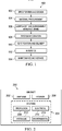
- aircraft manufacturing and service method 100 may be described in the context of aircraft manufacturing and service method 100 as shown in Figure 1 and aircraft 200 as shown in Figure 2 .
- Figure 1 an illustration of an aircraft manufacturing and service method is depicted in accordance with an advantageous embodiment.
- aircraft manufacturing and service method 100 may include specification and design 102 of aircraft 200 in Figure 2 and material procurement 104.
- aircraft 200 in Figure 2 During production, component and subassembly manufacturing 106 and system integration 108 of aircraft 200 in Figure 2 takes place. Thereafter, aircraft 200 in Figure 2 may go through certification and delivery 110 in order to be placed in service 112. While in service 112 by a customer, aircraft 200 in Figure 2 may be scheduled for routine maintenance and service 114, which may include modification, reconfiguration, refurbishment, and other maintenance or service.
- Each of the processes of aircraft manufacturing and service method 100 may be performed or carried out by a system integrator, a third party, and/or an operator.
- the operator may be a customer.
- a system integrator may include, without limitation, any number of aircraft manufacturers and major-system subcontractors
- a third party may include, without limitation, any number of venders, subcontractors, and suppliers
- an operator may be an airline, leasing company, military entity, service organization, and so on.
- aircraft 200 may be produced by aircraft manufacturing and service method 100 in Figure 1 and may include airframe 202 with a plurality of systems 204 and interior 206.
- systems 204 may include one or more of propulsion system 208, electrical system 210, hydraulic system 212, and environmental system 214. Any number of other systems may be included.
- an aerospace example is shown, different advantageous embodiments may be applied to other industries, such as the automotive industry.
- Apparatus and methods embodied herein may be employed during at least one of the stages of aircraft manufacturing and service method 100 in Figure 1 .
- the phrase "at least one of”, when used with a list of items, means that different combinations of one or more of the listed items may be used and only one of each item in the list may be needed.
- "at least one of item A, item B, and item C" may include, for example, without limitation, item A or item A and item B. This example also may include item A, item B, and item C or item B and item C.
- components or subassemblies produced in component and subassembly manufacturing 106 in Figure 1 may be fabricated or manufactured in a manner similar to components or subassemblies produced while aircraft 200 is in service 112 in Figure 1 .
- a number of apparatus embodiments, method embodiments, or a combination thereof may be utilized during production stages, such as component and subassembly manufacturing 106 and system integration 108 in Figure 1 .
- a number when referring to items, means one or more items.
- a number of apparatus embodiments may be one or more apparatus embodiments.
- a number of apparatus embodiments, method embodiments, or a combination thereof may be utilized while aircraft 200 is in service 112 and/or during maintenance and service 114 in Figure 1 .
- the use of a number of the different advantageous embodiments may substantially expedite the assembly of and/or reduce the cost of aircraft 200.
- the different advantageous embodiments recognize and take into account a number of considerations. For example, without limitation, the different advantageous embodiments recognize and take into account that smaller robotic machines may be used to reach locations on or within a structure that larger robotic machines may not be able to reach. The different advantageous embodiments recognize and take into account that in locations in which larger robotic machines cannot be used, smaller robotic machines may be employed.
- some robotic machines may move on the structure being assembled. These robotic machines may use a rail system for movement.
- a rail system may be attached to the structure.
- a rail system may be attached to the structure.
- the robotic machine may then move along the rails and perform operations to fasten the skin panels to the ribs.
- These robotic machines may drill holes and insert fasteners to attach skin panels to the ribs of the structure.
- the different advantageous embodiments recognize that the use of robotic machines with rail systems may be cumbersome and more time consuming than desired.
- the rails may need to be repositioned from location to location. This repositioning may require removing the robotic machine, removing the rail, reinstalling the rail in the new location, and then placing the robotic machine back onto the rail.
- the robotic machines may have legs with suction cups.
- Those suction cups may engage and disengage themselves from the panels and move to different locations to perform operations.
- the movement of the legs along with the engagement and disengagement of the suction cups may occur in a manner that moves the machine.
- the different advantageous embodiments recognize and take into account that these currently used machines may have a first frame and a second frame.
- the frames may move relative to each other.
- the legs on both frames may have suction cups that attach to the surface of the structure when a vacuum is applied.
- the suction cups for the legs on one frame may be disengaged. Those legs may then be raised away from the surface of the structure.
- the first frame may then move relative to the second frame. Thereafter, the legs may be extended back onto the surface.
- a vacuum may be applied to the suction cups to reengage the suction cups to the surface.
- the suction cups or the legs on the second frame may be disengaged from the surface of the structure. Those legs may then be retracted.
- the second frame may move relative to the first frame. Thereafter, the legs may be re-extended and the suction cups may be engaged to the surface.
- the different advantageous embodiments recognize and take into account that with these types of frames that move in parallel to each other, the systems may be more complex, heavier, and slower than desired. Further, the different advantageous embodiments also recognize that with the use of these types of systems, additional safety features may be needed. These safety features may include additional straps or lines to secure the robotic machine in case the vacuum generated by the suction cups does not provide the needed amount of vacuum to maintain attachment to the structure.
- an apparatus may comprise a frame system, a first number of suction cups, a second number of suction cups, and a controller.
- the frame system may have a first frame and a second frame in which the frame system may be configured to hold an end effector that is configured to perform a number of operations.
- the first frame and the second frame may be configured for attachment to a workpiece.
- the controller may be configured to control attachment of the first frame and the second frame to the workpiece by applying a vacuum and a pressure during movement of the frame system.
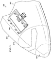
- manufacturing environment 300 may be an example of an environment that may be used to manufacture structures for aircraft 302.
- Aircraft 302 may be an example of one implementation for aircraft 200 in Figure 2 .
- Aircraft 302 may have fuselage 304 and nose 306.
- crawler assembly system 308 may be used to manufacture structures for aircraft 302.
- Crawler assembly system 308 may be an example of a robotic machine in this illustrative example.
- Crawler assembly system 308 may be used during at least one of component and subassembly manufacturing 106, system integration 108, maintenance and service 114, and/or other suitable phases during aircraft manufacturing and service method 100 in Figure 1 .
- crawler assembly system 308 may be placed on surface 310 of fuselage 304. As one illustrative example, crawler assembly system 308 may be used to install fasteners onto surface 310 of fuselage 304. Additionally, crawler assembly system 308 may be used to perform a number of other operations to manufacture structures for aircraft 302.
- Manufacturing environment 400 is an example of an environment that may be used to manufacture structures for aircraft 200 in Figure 2 .
- manufacturing environment 300 in Figure 3 may be an example of one implementation for manufacturing environment 400 in Figure 4 .
- manufacturing environment 400 may be used during at least one of component and subassembly manufacturing 106, system integration 108, maintenance and service 114, and other suitable phases during aircraft manufacturing and service method 100 in Figure 1 .
- crawler assembly system 402 may perform number of operations 404 on workpiece 406.
- workpiece 406 may be a structure or a portion of a structure for aircraft 200 in Figure 2 .
- workpiece 406 may be for other types of objects other than aircraft 200 in Figure 2 .
- workpiece 406 may be for an automobile, a truck, a building, a spacecraft, a missile, a ship, a submarine, a dam, a bridge, and/or some other suitable type of object.
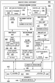
- crawler assembly system 402 may comprise frame system 408, controller 410, electromagnetic unit 412, vacuum and pressure unit 414, end effector 416, sensor system 418, and other suitable components.
- crawler assembly system 402 may be referred to as an electromagnetic crawler assembly system.
- Frame system 408 may comprise first frame 420, second frame 422, movement system 424, first number of legs 426, second number of legs 428, first number of suction cups 430, second number of suction cups 432, and/or other suitable components. Frame system 408 may be configured to hold end effector 416.
- first frame 420 and second frame 422 may move relative to each other.
- Movement system 424 may cause first frame 420 and second frame 422 to move relative to each other.
- movement system 424 may comprise number of motors 434.
- First number of suction cups 430 may be associated with first frame 420 and may be configured for attachment to workpiece 406.
- Second number of suction cups 432 may be associated with second frame 422. Second number of suction cups 432 may be configured for attachment to workpiece 406.
- a first component may be considered to be associated with a second component by being secured to the second component, bonded to the second component, fastened to the second component, and/or connected to the second component in some other suitable manner.
- the first component also may be connected to the second component through using a third component.
- the first component may also be considered to be associated with the second component by being formed as part of and/or an extension of the second component.
- first number of suction cups 430 may be associated with first frame 420 using first number of legs 426.
- Second number of suction cups 432 may be associated with second frame 422 using second number of legs 428.
- first number of suction cups 430 and second number of suction cups 432 may be a removable attachment.
- the attachment may be caused by vacuum 436 applied by vacuum and pressure unit 414.
- Vacuum 436 may be applied to first number of suction cups 430 through first number of legs 426 and to second number of suction cups 432 through second number of legs 428 in these examples.
- Vacuum 436 may cause first number of suction cups 430 and second number of suctions cups 432 to be attached to workpiece 406.
- vacuum 436 may be applied through at least a portion of first number of suction cups 430 and second number of suction cups 432 to attach portion 438 of first number of suction cups 430 and/or portion 439 of second number of suction cups 432 to surface 440 of workpiece 406.
- first number of suction cups 430 and second number of suction cups 432 may have a number of different shapes and/or sizes.
- first number of legs 426 and second number of legs 428 may be moveable relative to surface 440 of workpiece 406.
- First number of legs 426 and second number of legs 428 may be moveable to conform to surface 440.
- surface 440 may be curved about one or more different axes (not shown).
- First number of legs 426 and/or second number of legs 428 may be moved relative to surface 440 to allow first number of suction cups 430 and/or second number of suction cups 432 to contact surface 440.
- vacuum 436 may be applied to attach first number of suction cups 430 and/or second number of suction cups 432 to surface 440 of workpiece 406.
- the positioning or movement of first number of legs 426 and/or second number of legs 428 may be performed using movement system 424.
- first number of suction cups 430 and second number of suction cups 432 may be attached to surface 440 of workpiece 406 during the performance of number of operations 404.
- end effector 416 may perform number of operations 404 under the control of controller 410.
- End effector 416 may comprise at least one of drill unit 441, fastener system 443, sealant unit 445, vision system 447, and/or other suitable devices.
- End effector 416 may be a device that may be moved by crawler assembly system 402 to different locations on workpiece 406 to perform number of operations 404.
- number of operations 404 may be performed at location 444 within area 442 of workpiece 406.
- Area 442 may be an area within which end effector 416 may be moved by crawler assembly system 402 without moving frame system 408. After number of operations 404 have been performed, crawler assembly system 402 may be moved to location 448.
- end effector 416 may be stabilized using electromagnetic unit 412.
- Electromagnetic unit 412 may be associated with first frame 420. Electromagnetic unit 412 may engage magnetic material 446 on workpiece 406 to provide better attachment of crawler assembly system 402 to workpiece 406 during performance of number of operations 404. This provides attachment in addition to applying vacuum 436 to first number of suction cups 430 and second number of suction cups 432.
- vacuum 436 When moving from location 444 to location 448, vacuum 436 may be applied to first number of suction cups 430 and pressure 450 may be applied to second number of suction cups 432. Pressure 450 may provide force 452 to lift second frame 422 away from surface 440 of workpiece 406.
- first number of suction cups 430 and second number of suction cups 432 may also be configured to apply vacuum 436 and/or pressure 450.
- Suction cups of various geometries may be used to implement first number of suction cups 430 and second number of suction cups 432. Examples of suction cups that may be used include, for example, without limitation, suction cups available from Piab USA, Inc.
- Second frame 422 may be moved relative to first frame 420 by movement system 424 while pressure 450 is applied to second number of suction cups 432 and vacuum 436 is applied to first number of suction cups 430. After movement of second frame 422 has completed, vacuum 436 may be applied to second number of suction cups 432.
- pressure 450 may be applied to first number of suction cups 430 while vacuum 436 is applied to second number of suction cups 432. Then, first frame 420 may be moved relative to second frame 422 while vacuum 436 is applied to second number of suction cups 432 and pressure 450 is applied to first number of suction cups 430. This sequence of steps may be performed to move workpiece 406 from location 444 to location 448.
- first frame 420 and second frame 422 may move relative to each other to move frame system 408 from location 444 to location 448, while end effector 416 performs number of operations 404. In this manner, pauses in the performance of number of operations 404 for movement of crawler assembly system 402 may be reduced and/or avoided.
- electromagnetic unit 412 may provide force 454 to hold first frame 420 on workpiece 406, while second frame 422 moves relative to first frame 420. Additionally, electromagnetic unit 412 may provide an additional mechanism to hold crawler assembly system 402 on workpiece 406 in case first number of suction cups 430 and second number of suction cups 432 are unable to hold frame system 408 on workpiece 406.
- controller 410 may comprise a computer, a processor unit, an application specific integrated circuit, or some other suitable device that controls the operation of crawler assembly system 402. Controller 410 may be configured to control attachment of first frame 420 and second frame 422 to workpiece 406 by applying vacuum 436 and pressure 450 during movement of frame system 408. Controller 410 may store locations and/or operations to be performed on workpiece 406 in the form of program code 456. Program code 456 may be run to perform number of operations 404 on workpiece 406.
- Sensor system 418 in these illustrative examples, may be used to identify the location of crawler assembly system 402 on workpiece 406. Further, sensor system 418 may be used to position end effector 416 relative to workpiece 406. Sensor system 418 also may be used to perform inspections on number of operations 404. In these illustrative examples, sensor system 418 may comprise, for example, without limitation, infrared sensors, cameras, ultrasonic sensors, and/or other suitable types of sensors.
- manufacturing environment 400 is not meant to imply physical architectural limitations to the manner in which different advantageous embodiments may be implemented.
- Other components in addition to and/or in place of the ones illustrated may be used. Some components may be unnecessary in some advantageous embodiments.
- the blocks are presented to illustrate some functional components. One or more of these blocks may be combined and/or divided into different blocks when implemented in different advantageous embodiments.
- crawler assembly systems in addition to crawler assembly system 402 may be present to perform operations on workpiece 406.
- crawler assembly system 402 may comprise a number of additional end effectors in addition to end effector 416.
- additional electromagnetic units in addition to electromagnetic unit 412 may be present.
- first leg 458 and second leg 462 in first number of legs 426 may be configured to rotate about axis 460.
- the rotation of first leg 458 and/or second leg 462 about axis 460 may cause electromagnetic unit 412 to rotate about axis 460.
- the positioning of electromagnetic unit 412 may be performed for different types of surfaces on workpiece 406.
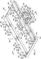
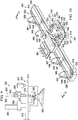
- crawler assembly system 500 may be an example of one implementation for crawler assembly system 308 in Figure 3 and/or crawler assembly system 402 in Figure 4 .
- Crawler assembly system 500 may include frame system 502, electromagnetic unit 504, vacuum and pressure unit 506, end effector 508, sensor system 510, and controller 512.
- frame system 502 may comprise first frame 514, second frame 516, movement system 518, first number of legs 520, second number of legs 522, first number of suction cups 524, and second number of suction cups 526.
- second frame 516 may include portion 511 and portion 513. Portion 511 and portion 513 may be attached to each other to form second frame 516. Further, first frame 514 may be associated with portion 513 of second frame 516.
- First frame 514 and second frame 516 may move relative to each other using movement system 518.
- Movement system 518 may include motor 528 in this illustrative example. Additionally, movement system 518 may include motors 552, 553, 554, 555, 556, 557, 558, 559, 560, and 561. Movement system 518 may be used to move at least a portion of first number of legs 520 relative to at least a first portion of second number of legs 522.
- first number of legs 520 and first number of suction cups 524 may be associated with first frame 514.
- First number of legs 520 may include leg 530 and leg 531.
- First number of suction cups 524 may include suction cup 532 and suction cup 533 attached to leg 530 and leg 531, respectively.
- First number of suction cups 524 may be configured to be attached to a surface of a workpiece (not shown), such as workpiece 406 in Figure 4 .
- Second number of legs 522 and second number of suction cups 526 may be associated with second frame 516.
- Second number of legs 522 may include legs 534, 535, 536, 537, 538, 539, 540, and 541.
- Second number of suction cups 526 may include suction cups 542, 543, 544, 545, 546, 547, and 548 attached to legs 534, 535, 536, 537, 538, 539, and 541, respectively, and another suction cup (not shown) attached to leg 540.
- Second number of suction cups 526 also may be configured to be attached to the surface of the workpiece.
- first number of legs 520 and second number of legs 522 may be moveable. Movement of first number of legs 520 and/or second number of legs 522 may be provided by movement system 518.
- motor 552 and motor 553 may move leg 530 and leg 531, respectively, vertically in the direction of arrow 549.
- motors 554, 555, 556, 557, 558, 559, 560, and 561 may be associated with legs 534, 535, 536, 537, 538, 539, 540, and 541, respectively.
- Each of these motors may be configured to move a corresponding leg vertically in the direction of arrow 549.
- Legs within first number of legs 520 and/or second number of legs 522 may be moved to different positions by movement system 518.
- first number of legs 520 and second number of legs 522 may be capable of substantially conforming to the surface of the workpiece when the surface is a curved surface.
- legs within first number of legs 520 and/or second number of legs 522 may be moved such that first number of suction cups 524 and second number of suction cups 526 may all contact the curved surface of the workpiece.
- Vacuum and pressure unit 506 may include lines that connect vacuum and pressure unit 506 to first number of legs 520 and second number of legs 522.
- vacuum and pressure unit 506 may include lines 562, 563, 564, 565, 566, 567, 568, and 569 that connect to legs 534, 535, 536, 537, 538, 539, 540, and 541, respectively. Further, vacuum and pressure unit 506 may include line 570 and line 571 that connect to leg 530 and leg 531, respectively. Vacuum and pressure unit 506 may apply a vacuum and/or pressure to these legs through these lines.
- Vacuum and pressure unit 506 may generate a vacuum such that at least a portion of first number of suction cups 524 and/or second number of suction cups 526 may attach to a surface of the workpiece.
- vacuum and pressure unit 506 may generate a vacuum through at least a portion of second number of legs 522 and/or first number of legs 520 such that at least a portion of first number of suction cups 524 and/or second number of suction cups 526 may attach to a surface of the workpiece.
- vacuum and pressure unit 506 may evacuate the air within at least a portion of first number of suction cups 524 and/or second number of suction cups 526 to generate the vacuum that allows attachment to the surface of the workpiece.
- first frame 514 may move relative to second frame 516 in the direction of arrow 549 and the direction of arrow 525 using vacuum and pressure unit 506 and movement system 518.
- vacuum and pressure unit 506 may apply a vacuum to first number of suction cups 524.
- the vacuum may cause first number of suction cups 524 to attach to the surface of the workpiece.
- Vacuum and pressure unit 506 may also apply pressure to second number of suction cups 526.
- vacuum and pressure unit 506 may pressurize second number of suction cups 526 instead of applying a vacuum to second number of suction cups 526.
- This pressurization may provide a force to lift second number of suctions cups 526 off the surface of the workpiece.
- the pressurization of second number of suction cups 526 may be provided by a cushion of air in this illustrative example. In this manner, second frame 516 may be lifted off of the surface of the workpiece by the pressure applied by vacuum and pressure unit 506.
- motor 528 may be operated to move second frame 516 relative to first frame 514.
- Second frame 516 may be moved in the direction of arrow 525 while first frame 514 remains attached to the surface of the workpiece by first number of suction cups 524.
- vacuum and pressure unit 506 may apply a vacuum to second number of suction cups 526 to attach second number of suction cups 526 to the surface of the workpiece.
- crawler assembly system 500 may be moved over the surface of the workpiece by moving either first frame 514 or second frame 516 first.
- each suction cup in first number of suction cups 524 and second number of suction cups 526 may have a flexibility that may allow each suction cup to attach to a curved surface. Further, this flexibility may allow at least a portion of first number of suction cups 524 and/or second number of suction cups 526 to attach to a surface at an angle relative to a surface to which another portion of first number of suction cups 524 and/or second number of suction cups 526 is attached. As one illustrative example, one portion of second number of suction cups 526 may be attached to a portion of a surface at a first angle and another portion of second number of suction cups 526 may be attached to another portion of the surface at a second angle.
- crawler assembly system 500 may also have motor 550 and motor 551 associated with first frame 514.
- Motor 550 and motor 551 may be electric motors, air motors, air cylinders, and/or some other suitable type of motor.
- Motor 550 and motor 551 may be used to rotate at least one of leg 530 and leg 531.
- leg 530 may be rotated in a first direction about axis 590
- leg 531 may be rotated in a second direction about axis 590.
- Rotation of leg 530 and leg 531 while a vacuum is applied to suction cup 532 and suction cup 533, may cause rotation of frame system 502 about axis 592.
- Rotation of frame system 502 about axis 592 may cause crawler assembly system 500 to turn on the surface of a workpiece.
- motor 550 and motor 551 may be used to rotate leg 530 and leg 531 such that suction cup 532 and suction cup 533 may contact a curved surface for the workpiece.
- electromagnetic unit 504 may provide additional attachment of crawler assembly system 500 to the workpiece.
- electromagnetic unit 504 may provide additional attachment of crawler assembly system 500 to the workpiece if any of the suctions cups in first number of suction cups 524 or second number of suction cups 526 do not attach to the workpiece as desired.
- end effector 508 may be used to perform a number of operations on the workpiece.
- end effector 508 may include drill unit 580 and fastener system 581.
- Drill unit 580 may be used to perform drilling operations
- fastener system 581 may be used to perform fastening operations. These operations may be performed while first frame 514 is attached to the workpiece.
- Second frame 516 may be attached to the workpiece or may be moving towards a desired location while the operations are performed by end effector 508.
- sensor system 510 may be used to generate information about the surface of the workpiece on which the operations are to be performed.
- sensor system 510 may include camera 582 in this depicted example.
- Camera 582 may be used to generate image information used to identify the location at which the operations are to be performed. Further, the image information may also be used for positioning drill unit 580 and/or fastener system 581 for performing the operations.
- controller 512 may be associated with first frame 514. Controller 512 may take the form of computer system 584 in this depicted example.
- Computer system 584 may be used to control crawler assembly system 500.
- computer system 584 may be used to control the movement of crawler assembly system 500 by movement system 518, the positioning of end effector 508, the types of operations performed by end effector 508, and/or other suitable operations.
- controller 512 may be operated manually and/or automatically.
- controller 512 may run program code to control crawler assembly system 500.
- controller 512 may be operated by a human operator.
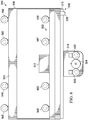
- FIG. 6 an illustration of a bottom view of a crawler assembly structure is depicted in accordance with an advantageous embodiment.
- suction cup 600 in second number of suction cups 526 for crawler assembly system 500 in Figure 5 may be seen.
- Suction cup 600 may be associated with leg 540 in second number of legs 522 in Figure 5 .
- crawler assembly system 500 may be seen from the front of first frame 514. As depicted, crawler assembly system 500 may be placed on workpiece 700. In particular, suction cups 546, 547, 600, and 548 may be seen attached to surface 702 of workpiece 700.
- crawler assembly system 500 may use motor 550 to rotate leg 530 about axis 590 substantially perpendicular to axis 592.
- Leg 530 may be rotated about axis 590 such that center line 802 for leg 530 may be rotated about plus or minus five degrees away from axis 592 in the direction of arrow 800.
- FIG. 9 an illustration of a cross-sectional side view of a portion of a crawler assembly system is depicted in accordance with an advantageous embodiment.
- center line 802 for leg 530 has been rotated to position 900.
- position 900 may be about plus five degrees away from axis 592.
- the rotation of leg 530 may be caused by the operation of motor 550 in this illustrative example.
- leg 531 in Figure 5 may also be rotated to a position away from axis 592 in a direction opposite to the rotation of leg 530 in this illustrative example. Rotation of these two legs in opposite directions may cause frame system 502 to rotate about axis 592. In this manner, crawler assembly system 500 may be turned using motor 550 and motor 551 in Figure 5 to rotate leg 530 and leg 531, respectively.
- crawler assembly system 500 may have a different configuration as compared to the configuration for crawler assembly system 500 in Figure 5 .
- portion 511 of second frame 516 may be removed. Only portion 513 of second frame 516 may be present for crawler assembly system 500. Removal of portion 511 may reduce the size and/or weight of crawler assembly system 500. This reduction in size and/or weight may allow crawler assembly system 500 to move to a greater number of locations and be in a greater number of positions as compared to when portion 511 is present for crawler assembly system 500.
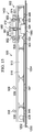
- FIG. 11 an illustration of a back view of a crawler assembly system placed on a workpiece is depicted in accordance with an advantageous embodiment.
- a back view of crawler assembly system 500 may be illustrated taken along lines 11-11 in Figure 10 .
- crawler assembly system 500 may be shown from the view of controller 512.
- crawler assembly system 500 may be placed on workpiece 1100.
- Workpiece 1100 may have curved surface 1102 in this illustrative example.
- Legs 538, 539, 540, and 541 may be moved such that suction cup 546, 547, 600, and 548 are in contact with curved surface 1102.
- suction cup 532 and suction cup 533 may not be in contact with curved surface 1102 such that first frame 514 may be moved along axis 1104.
- vacuum and pressure unit 506 may apply pressure to suction cup 532 and suction cup 533.
- the vacuum applied to suction cup 532 and suction cup 533 may be removed by pressurizing suction cup 532 and suction cup 533.
- This pressurization of these suction cups may provide the force needed to lift suction cup 532 and suction cup 533 off of curved surface 1102.
- this force may be provided by, for example, without limitation, cushion of air 1106 under suction cup 532 and cushion of air 1108 under suction cup 533.
- first frame 514 may be moved along axis 1104 to a desired location.
- leg 530 in Figure 9 and leg 531 in Figure 7 may be moved such that suction cup 532 and suction cup 533 may not come in contact with curved surface 1102 while first frame 514 is moved.
- leg 530 and leg 531 may not need to be moved, because cushion of air 1106 and cushion of air 1108 may provide force sufficient to lift suction cup 532 and suction cup 533, respectively, off of curved surface 1102 as first frame 514 is moved along axis 1104.
- crawler assembly system 500 in Figures 12-15 has the configuration presented in Figure 10 .
- crawler assembly system 500 may be placed on workpiece 1200.
- Suction cups 532, 533, 546, 547, 600, and 548 may be attached to surface 1202 of workpiece 1200.
- Suction cups 532, 533, 546, 547, 600, and 548 may be attached to surface 1202 using a vacuum provided by vacuum and pressure unit 506.
- electromagnetic unit 504 may attach to magnetic material 1204 positioned under workpiece 1200 to provide additional attachment of crawler assembly system 500 to workpiece 1200 in addition to the attachment provided by suction cups 532, 533, 546, 547, 600, and 548.
- first frame 514 may be in position 1206 on workpiece 1200.
- First frame 514 may be in position 1206 such that fastener unit 581 may be placed over location 1208 on workpiece 1200.
- Fastener unit 581 for end effector 508 may be used to perform fastening operations at location 1208 on workpiece 1200.
- controller 512 may release the attachment of electromagnetic unit 504 from surface 1202 of workpiece 1200. Further, vacuum and pressure unit 506 may apply pressure to suction cup 532 and suction cup 533 to lift suction cup 532 and suction cup 533 off of surface 1202.
- first frame 514 may be moved from position 1204 in Figures 12 and 13 in the direction of arrow 1400 to position 1402. Second frame 516 may not move while first frame 514 is moved.
- controller 512 may control electromagnetic unit 504 such that electromagnetic unit 504 attaches to surface 1202.
- vacuum and pressure unit 506 may apply a vacuum to suction cup 532 and suction cup 533 such that suction cup 532 and suction cup 533 attach to surface 1202.
- fastener system 581 may be used to perform fastening operations at location 1500 on workpiece 1200.
- crawler assembly system 1600 may be an example of one implementation of crawler assembly system 402 in Figure 4 and/or crawler assembly system 308 in Figure 3 .
- crawler assembly system 1600 may include frame system 1602, electromagnetic unit 1604, vacuum and pressure unit 1606, end effector 1608, and sensor system 1610.
- Frame system 1602 may comprise first frame 1612, second frame 1614, movement system 1616, first number of legs 1618, second number of legs 1620, first number of suction cups 1622, and second number of suction cups 1624.
- first frame 1612 may be positioned within interior 1615 of second frame 1614.
- This configuration for crawler assembly system 1600 may be different than the configuration for crawler assembly system 500 in Figure 5 and in Figure 9 .
- First number of legs 1618 may be associated with first frame 1612 and may include leg 1640 and leg 1641.
- Second number of legs 1620 may be associated with second frame 1614 and may include legs 1626, 1627, 1628, 1629, 1630, 1631, 1632, 1633, 1634, 1635, 1636, 1637, 1638, and 1639.
- First number of suction cups 1622 may include suction cup 1643 attached to leg 1641 and another suction cup (not shown) attached to leg 1640.
- Second number of suction cups 1624 may include suction cups 1644, 1645, 1646, 1647, 1648, 1649, 1650, 1651, 1652, 1653, 1654, 1655, 1656, and 1657 attached to legs 1626, 1627, 1628, 1629, 1630, 1631, 1632, 1633, 1634, 1635, 1636, 1637, 1638, and 1639, respectively.
- movement system 1616 may be configured to move first frame 1612 relative to second frame 1614. Movement system 1616 may be configured to move first frame 1612 and/or second frame 1614 along axis 1617.
- movement system 1616 may be configured to move first number of legs 1618 and/or second number of legs 1620 vertically such that first number of suction cups 1622 and/or second number of suction cups 1624 may all contact the surface of a workpiece (not shown).
- Movement system 1616 may include motors 1658, 1659, 1660, 1661, 1662, 1663, 1664, 1665, 1666, 1667, 1668, 1669, 1670, and 1671 associated with legs 1626, 1627, 1628, 1629, 1630, 1631, 1632, 1633, 1634, 1635, 1636, 1637, 1638, and 1639, respectively. Further, movement system 1616 may include motor 1672 associated with leg 1640, motor 1673 associated with leg 1641, and/or other suitable motors not shown in this view.
- motor 1676 and motor 1677 may be associated with first frame 1612. Motor 1676 may tilt leg 1640 and/or motor 1677 may tilt leg 1641 relative to the surface of the workpiece such that first number of suction cups 1622 may conform to the surface of the workpiece.
- Electromagnetic unit 1604 may provide additional attachment for crawler assembly system 1600 to a workpiece. Additionally, end effector 1608 may include fastener system 1678 and drill unit 1680. Fastener system 1678 and drill unit 1680 may be associated with first frame 1612. Fastener system 1678 may be used to perform fastening operations on the workpiece. Drill unit 1680 may be used to perform drilling operations on the workpiece.
- Sensor system 1610 may be used to identify the location on the workpiece at which to perform operations. Further, sensor system 1610 may be used to position end effector 1608 to perform the operations and/or inspect the operations being performed.
- FIG. 17 an illustration of a flowchart of a process for performing operations on a workpiece is depicted in accordance with an advantageous embodiment.
- the process illustrated in Figure 17 may be implemented using crawler assembly system 402 in Figure 4 .
- Crawler assembly system 402 may comprise frame system 408 having first frame 420, second frame 422, first number of suction cups 430, second number of suction cups 432, and controller 410.
- Frame system 408 may be configured to hold end effector 416.
- End effector 416 may be configured to perform number of operations 404.
- the process may then move crawler assembly system 402 to the selected location (operation 1702 ).
- the process may perform number of operations 404 at the selected location on workpiece 406 (operation 1704 ).
- the process may determine whether another location is present for processing (operation 1706 ). If another location is present for processing, the process returns to operation 1700. Otherwise, the process may terminate.
- FIG. 18 an illustration of a flowchart of a process for moving a crawler assembly system is depicted in accordance with an advantageous embodiment.
- the process illustrated in Figure 18 may be implemented using crawler assembly system 402 in Figure 4 .
- This process may be a more-detailed process for operation 1702 in Figure 17 .
- the process may begin by applying pressure 450 to first number of suction cups 430 (operation 1800 ).
- Pressure 450 may provide force 452 that may lift first number of suction cups 430 off of surface 440 of workpiece 406.
- vacuum 436 may be applied to second number of suction cups 432 such that second number of suction cups 432 may be attached to surface 440 of workpiece 406.
- the process may then disengage electromagnetic unit 412 from workpiece 406 (operation 1802 ).
- the process may move first frame 420 to a selected location (operation 1804 ).
- Second frame 422 may not move when first frame 420 is moved to the selected location.
- the process may apply vacuum 436 to first number of suction cups 430 (operation 1806 ).
- the process may engage electromagnetic unit 412 such that electromagnetic unit 412 attaches to workpiece 406 (operation 1808) .
- the process may then apply pressure to second number of suction cups 432 to remove vacuum 436 applied to second number of suction cups 432 (operation 1810 ).
- the process may move second frame 422 (operation 1812 ).
- the process may determine whether movement of crawler assembly system 402 to the selected location has been completed (operation 1814 ). If movement of crawler assembly system 402 to the selected location has not been completed, the process may return to operation 1800 as described above. Otherwise, the process may terminate.
- FIG. 19 an illustration of a flowchart of a process for adjusting the legs of a crawler assembly system is depicted in accordance with an advantageous embodiment.
- the process illustrated in Figure 19 may be implemented using crawler assembly system 402 in Figure 4 .
- the process may begin by identifying the contour of surface 440 of workpiece 406 (operation 1900 ).
- the contour may be identified as curved, jagged, straight, and/or having some other type of contour.
- the contour may be identified as a complex contour in which the contour is curved in at least two directions.
- the process may select a number of legs within first number of legs 426 and/or second number of legs 428 (operation 1902 ). The process may then adjust the selected number of legs (operation 1904 ), with the process terminating thereafter.
- the selected number of legs may be adjusted by moving at least a portion of the selected number of legs vertically to adjust for the contour of surface 440. Further, the selected number of legs may be adjusted by tilting at least a portion of the selected number of legs in second number of legs 428 relative to surface 440. Tilting of this portion of the selected number of legs may allow electromagnetic unit 412 to be tilted such that electromagnetic unit 412 may attach to surface 440.
- each block in the flowcharts or block diagrams may represent a module, segment, function, and/or a portion of an operation or step.
- the function or functions noted in the block may occur out of the order noted in the figures.
- two blocks shown in succession may be executed substantially concurrently, or the blocks may sometimes be executed in the reverse order, depending upon the functionality involved.
- other blocks may be added in addition to the illustrated blocks in a flowchart or block diagram.
- operation 1706 may be performed while operation 1704 is being performed.
- the determination as to whether to move crawler assembly system 402 to another location may be made while operation 1704 is being performed.
- operations 1700 and 1702 may also be performed while operation 1704 is being performed.
- an apparatus may comprise a frame system, a first number of suction cups, a second number of suction cups, and a controller.
- the frame system may have a first frame and a second frame in which the frame system may be configured to hold an end effector.
- the end effector may be configured to perform a number of operations.
- the first number of suction cups may be associated with the first frame in which the first number of suction cups is configured for attachment to a workpiece.
- the second number of suction cups may be associated with the second frame in which the second number of suction cups may be configured for attachment to a workpiece.
- the controller may be configured to control an application of a vacuum and a pressure by the first number of suction cups and the second number of suction cups during movement of the first frame and the second frame relative to each other on the workpiece.
Landscapes
- Engineering & Computer Science (AREA)
- Mechanical Engineering (AREA)
- Transportation (AREA)
- Manufacturing & Machinery (AREA)
- Chemical & Material Sciences (AREA)
- Combustion & Propulsion (AREA)
- Aviation & Aerospace Engineering (AREA)
- Manipulator (AREA)
- Automatic Assembly (AREA)
- Automobile Manufacture Line, Endless Track Vehicle, Trailer (AREA)
- Machine Tool Units (AREA)
Description
- The present disclosure relates generally to manufacturing and, in particular, to a method and apparatus for attaching parts to each other. Still more particularly, the present disclosure relates to a method and apparatus for attaching parts to each other using a fastening system.
- In manufacturing structures, different parts may be connected to each other to form the structures. Aircraft structures, such as the wing and fuselage of an aircraft, may be manufactured by attaching parts to each other. For example, without limitation, panels may be placed onto ribs to form a fuselage. Panels also may be attached onto spars and ribs to form a wing for the aircraft.
- The attachment of these panels and other parts to each other may be performed by operators or computer-controlled machines. With operators, two operators may be located opposite to each other on a workpiece, such as a panel and a rib. The operators may install clamping devices to hold the parts together. Thereafter, a drill may be operated by one of the operators to create a hole. A rivet or other type of fastener may then be installed into the hole.
- This type of process may be time consuming and expensive. Large computer-controlled machines may be used to drill holes and install fasteners to fasten the parts to each other.
- In some cases, however, the shape of the structure and/or the location of fasteners may prohibit the use of these machines. In these cases, operators may still perform the drilling and fastener installation operations. As a result, depending on the design of the structure, the time and expense of installing fasteners may be greater than desired.
- Therefore, it would be advantageous to have a method and apparatus that takes into account one or more of the issues discussed above, as well as other possible issues.
-
EP0010034 discloses a vehicle able to move by adhesion on a random surface, with a central body defining a pivoting axis which remains substantially perpendicular to a surface and which has two groups of central supports which adhere to the surface; first and second carriages, each provided with two groups of adhesive end supports; first and second members for the guidance in rectilinear translation and without rotation of the first and second carriages in accordance with two directions which remain substantially orthogonal to the pivoting axis. The first and second carriages are displaceable along the guidance members; the first and second guidance members are pivotal about the pivot axis and the groups of central supports are rotatable about the pivot axis. -
EP1884453 discloses a crawler robot equipped with a work unit, and a control system for such crawler robots, the robot comprises a chassis with a first set of legs with suction pads on tilting supports mounted in a linearly displaceable manner with regard to the chassis and a second set of legs with suction pads mounted in a rotary manner with regard to the chassis. Certain control means are adapted in order to control the functioning of said first and second sets of legs in a coordinated manner for displacing the chassis in any direction on the work surface (S). It includes support feet and a system for levelling the chassis in relation to a curvature of the work surface. Fitted on the chassis is a work unit with a head for working on the work surface via an opening in the chassis. It includes means for displacing said head along three axes and pivoting the head on two axes with respect to the chassis. -
DE10318490 discloses a self driving working fixture combines a linear unit and a rotating unit together to provide translational and rotational movements to suction cups. A lifting unit at one of the suction cups provides necessary group clearance to the cups once these are rotated or translated. -
US5429009 discloses a movable robot for performing tasks upon and traversing a work surface. The robot having a first support means having a longitudinal axis. The first support means have first gripping means extending therefrom for detachable adhering the first support means to the work surface. The robot further having at least one second support means movably coupled to the first support means. Respective second gripping means extend from each second support means for detachable adhering the second support means to the work surface. The first and second gripping means are capable of being moved relative to one another both in a direction parallel to the longitudinal axis and along a line that intersects the longitudinal axis. At least one tool is attached to one or more of the first and second support means. -
JP1036587 - According to a first aspect of the invention, there is provided an apparatus as defined by
claim 1. - According to a second aspect of the invention, there is provided a method defined by claim 9.
- In one advantageous embodiment, an apparatus may comprise a frame system and a controller. The frame system may have a first frame and a second frame in which the frame system may be configured to hold an end effector that is configured to perform a number of operations. The first frame and the second frame may be configured for attachment to a workpiece. The controller may be configured to control attachment of the first frame and the second frame to the workpiece by applying a vacuum and a pressure during movement of the frame system.
- In another advantageous embodiment, a crawler assembly system may comprise a frame system, a first number of suction cups, a second number of suction cups, a controller, an electromagnetic unit, a vacuum and pressure unit, and an end effector. The frame system may be configured to hold an end effector that is configured to perform a number of operations on a workpiece. The frame system may comprise a first frame, a second frame, a first number of legs, a second number of legs, and a movement system. The first frame and the second frame may be configured to move relative to each other on the workpiece. A first leg in a first portion of the first number of legs may be configured to rotate about a first axis in a first direction. A second leg in a second portion of the first number of legs may be configured to rotate about the first axis in a second direction. Rotation of the first leg in the first direction and the second leg in the second direction about the first axis may cause rotation of the frame system about a second axis that is substantially perpendicular to a surface of the workpiece. The movement system may be configured to move the first frame and the second frame relative to each other. The movement system may be configured to move the first number of legs and the second number of legs to conform to the surface of the workpiece while the end effector is performing the number of operations on the workpiece. The first number of suction cups may be connected to the first frame by the first number of legs. The first number of suction cups may be configured for attachment to the workpiece. A first portion of the first number of suction cups may be connected to the first portion of the first number of legs, and a second portion of the first number of suction cups may be connected to the second portion of the first number of legs. The second number of suction cups may be connected to the second frame by the second number of legs. The second number of suction cups may be configured for attachment to the workpiece. The controller may be configured to control an application of a vacuum and a pressure by the first number of suction cups and the second number of suction cups during movement of the frame system. Movement of the first portion of the first number of legs in the first direction and movement of the second portion of the first number of legs in the second direction, while the vacuum is applied to the first portion of the first number of suction cups and to the second portion of the second number of suction cups and the pressure is applied to the second number of suction cups, may cause the frame system to turn on the surface of the workpiece. The electromagnetic unit may be associated with the first frame. The electromagnetic unit may be configured to attract a magnetic material associated with the workpiece such that the electromagnetic unit may hold the first frame on the workpiece. A channel may extend through the electromagnetic unit and may be configured to receive an end of the end effector and allow the end of the end effector to reach a surface of the workpiece. The vacuum and pressure unit may be connected to the first number of suction cups and the second number of suction cups. The vacuum and pressure unit may be configured to apply at least one of the vacuum and the pressure to the first number of suction cups and the second number of suction cups. The end effector may comprise at least one of a drill unit, a fastener system, a sealant unit, and a vision system.
- In yet another advantageous embodiment, a method may be provided for performing operations on a workpiece. A first frame in a frame system may be held on the workpiece by applying a vacuum to the first frame. A second frame in the frame system may be detached from the workpiece by applying a pressure to the second frame. The second frame may be moved to a location on the workpiece. The second frame may be attached to the workpiece by applying the vacuum to the second frame. An operation may be performed on the workpiece.
- In still yet another advantageous embodiment, a method may be provided for performing operations on a workpiece. A crawler assembly system may be moved from a first location to a second location. The crawler assembly system may comprise a frame system, a first number of suction cups, a second number of suction cups, and a controller. The frame system may have a first frame and a second frame in which the frame system may be configured to hold an end effector that may be configured to perform a number of operations. The first number of suction cups may be associated with the first frame by a number of legs. The first number of suction cups may be configured for attachment to the workpiece. The second number of suction cups may be associated with the second frame. The second number of suction cups may be configured for attachment to the workpiece. The controller may be configured to control an application of a vacuum and a pressure by the first number of suction cups and the second number of suction cups during movement of the frame system. Moving the crawler assembly system from the first location to the second location may comprise applying the vacuum to the first number of suction cups and the pressure to the second number of suction cups, moving the second frame relative to the first frame while the first number of suction cups holds the first frame to the workpiece, applying the vacuum to the second number of suction cups after movement of the second frame, applying the pressure to the first number of suction cups after the vacuum is applied to the second number of suction cups, moving the first frame relative to the second frame while the second number of suction cups holds the second frame to the workpiece, and repeating the steps of applying the vacuum to the first number of suction cups and the pressure to the second number of suction cups, moving the second frame relative to the first frame while the first number of suction cups holds the first frame to the workpiece, applying the vacuum to the second number of suction cups after movement of the second frame, applying the pressure to the first number of suction cups after the vacuum is applied to the second number of suction cups, and moving the first frame relative to the second frame while the second number of suction cups holds the second frame to the workpiece until the second location is reached. The vacuum may be applied to a first portion of the first number of suction cups connected to a first portion of the number of legs and to a second portion of the first number of suction cups connected to a second portion of the number of legs. The pressure may be applied to the second number of suction cups. A first leg in the first portion of the number of legs may be rotated in a first direction around a first axis. A second leg in the second portion of the first number of legs may be rotated in a second direction about the first axis. Rotation of the first leg and the second leg may cause rotation of the frame system about a second axis that is substantially perpendicular to the surface of the workpiece. The number of operations may be performed at the location on the workpiece.
- In preferred embodiments, a number of legs connect the first number of suction cups to the first frame and wherein movement of a first portion of the number of legs in a first direction and movement of a second portion of the number of legs in a second direction, while the vacuum is applied to a first portion of the first number of suction cups connected to the first portion of the number of legs and to a second portion of the first number of suction cups connected to the second portion of the number of legs and the pressure is applied to the second number of suction cups, causes the frame system to turn on a surface of the workpiece.
- Preferred embodiments further comprise:
an electromagnetic unit associated with the first frame, wherein the electromagnetic unit is configured to attract a magnetic material associated with the workpiece such that the electromagnetic unit holds the first frame on the workpiece, wherein a channel extends through the electromagnetic unit and is configured to receive the end effector and allow the end effector to reach a surface of the workpiece. - Preferably,wherein the channel is configured to receive an end of the end effector and allow the end of the end effector to reach the surface of the workpiece.
- Preferred embodiments further comprise:
- a first leg in the first portion of the number of legs, wherein the first leg is configured to rotate about a first axis in the first direction; and
- a second leg in the second portion of the number of legs, wherein the second leg is configured to rotate about the first axis in the second direction, wherein rotation of the first leg in the first direction and the second leg in the second direction about the first axis causes rotation of the frame system about a second axis that is substantially perpendicular to the surface of the workpiece.
- The apparatus may further comprise:
a vacuum and pressure unit connected to a first number of suction cups and a second number of suction cups, wherein the vacuum and pressure unit is configured to apply at least one of the vacuum and the pressure to the first number of suction cups and the second number of suction cups. - The frame system may further comprise:
a movement system configured to move the first frame and the second frame relative to each other. - The frame system may further comprise:
- a first number of legs connecting a first number of suction cups to the first frame; and
- a second number of legs connecting a second number of suction cups to the second frame.
- Preferably, a movement system is configured to move the first number of legs and the second number of legs to conform to a surface of the workpiece while the end effector is performing the number of operations on the workpiece.
- The controller may be configured to apply the vacuum to a first number of suction cups to cause the vacuum to be present in each of the first number of suction cups and the pressure to a second number of suction cups to pressurize each suction cup in the second number of suction cups; move the second frame relative to the first frame while the vacuum present in the each suction cup in the second number of suction cups holds the first frame to the workpiece; apply the vacuum to the second number of suction cups to cause the vacuum to be present in each of the second number of suction cups after movement of the second frame; apply the pressure to the first number of suction cups to pressurize the each suction cup in the first number of suction cups after the vacuum is applied to the second number of suction cups; move the first frame relative to the second frame while the vacuum present in the each suction cup in the second number of suction cups holds the second frame to the workpiece.
- The apparatus of may further comprise:
an electromagnetic unit associated with the first frame, wherein the electromagnetic unit is configured to attract a magnetic material associated with the workpiece such that the electromagnetic unit holds the first frame on the workpiece during the movement of the second frame. - The application of the pressure by the first number of suction cups and the second number of suction cups can provide a force to lift.
- The apparatus may further comprisean end effector.
- Preferably, the end effector comprises at least one of a drill unit, a fastener system, a sealant unit, and a vision system.
- A preferred embodiment provides a crawler assembly system comprising:
- a frame system configured to hold an end effector that is configured to perform a number of operations on a workpiece in which the frame system comprises:
- a first frame;
- a second frame in which the first frame and the second frame are configured to move relative to each other on the workpiece;
- a first number of legs in which a first leg in a first portion of the first number of legs is configured to rotate about a first axis in a first direction, in which a second leg in a second portion of the first number of legs is configured to rotate about the first axis in a second direction, and in which rotation of the first leg in the first direction and the second leg in the second direction about the first axis causes rotation of the frame system about a second axis that is substantially perpendicular to a surface of the workpiece;
- a second number of legs; and
- a movement system configured to move the first frame and the second frame relative to the each other and to move the first number of legs and the second number of legs to conform to the surface of the workpiece while the end effector is performing the number of operations on the workpiece;
- a first number of suction cups connected to the first frame by the first number of legs in which the first number of suction cups is configured for attachment to the workpiece and in which a first portion of the first number of suction cups is connected to the first portion of the first number of legs and a second portion of the first number of suction cups is connected to the second portion of the first number of legs;
- a second number of suction cups connected to the second frame by the second number of legs in which the second number of suction cups is configured for the attachment to the workpiece;
- a controller configured to control an application of a vacuum and a pressure by the first number of suction cups and the second number of suction cups during movement of the frame system in which movement of the first portion of the first number of legs in the first direction and movement of the second portion of the first number of legs in the second direction, while the vacuum is applied to the first portion of the first number of suction cups and to a second portion of the second number of suction cups and the pressure is applied to the second number of suction cups, causes the frame system to turn on the surface of the workpiece;
- an electromagnetic unit associated with the first frame in which the electromagnetic unit is configured to attract a magnetic material associated with the workpiece such that the electromagnetic unit holds the first frame on the workpiece and in which a channel extends through the electromagnetic unit and is configured to receive an end of the end effector and allow the end of the end effector to reach the surface of the workpiece;
- a vacuum and pressure unit connected to the first number of suction cups and the second number of suction cups in which the vacuum and pressure unit is configured to apply at least one of the vacuum and the pressure to the first number of suction cups and the second number of suction cups; and
- the end effector in which the end effector comprises at least one of a drill unit, a fastener system, a sealant unit, and a vision system.
- Preferably, the controller is configured to apply the vacuum to the first number of suction cups and the pressure to the second number of suction cups; move the second frame relative to the first frame while the second number of suction cups holds the first frame to the workpiece; apply the vacuum to the second number of suction cups after movement of the second frame; apply the pressure to the first number of suction cups after the vacuum is applied to the second number of suction cups; and move the first frame relative to the second frame while the second number of suction cups holds the second frame to the workpiece.
- A preferred method for performing operations on a workpiece, comprises:
moving a crawler assembly system from a first location to a second location in which the crawler assembly system comprises a frame system having a first frame and a second frame in which the frame system is configured to hold an end effector that is configured to perform a number of operations; a first number of suction cups associated with the first frame by a number of legs in which the first number of suction cups is configured for attachment to the workpiece; a second number of suction cups associated with the second frame in which the second number of suction cups is configured for attachment to the workpiece; and a controller configured to control an application of a vacuum and a pressure by the first number of suction cups and the second number of suction cups during movement of the frame system, in which the step of moving the crawler assembly system from the first location to the second location comprises: - applying the vacuum to the first number of suction cups and the pressure to the second number of suction cups;
- moving the second frame relative to the first frame while the first number of suction cups holds the first frame to the workpiece;
- applying the vacuum to the second number of suction cups after movement of the second frame;
- applying the pressure to the first number of suction cups after the vacuum is applied to the second number of suction cups;
- moving the first frame relative to the second frame while the second number of suction cups holds the second frame to the workpiece;
- repeating the steps of applying the vacuum to the first number of suction cups and the pressure to the second number of suction cups; moving the second frame relative to the first frame while the first number of suction cups holds the first frame to the workpiece; applying the vacuum to the second number of suction cups after the movement of the second frame; applying the pressure to the first number of suction cups after the vacuum is applied to the second number of suction cups; and moving the first frame relative to the second frame while the second number of suction cups holds the second frame to the workpiece until the second location is reached;
- applying the vacuum to a first portion of the first number of suction cups connected to a first portion of the number of legs and to a second portion of the first number of suction cups connected to a second portion of the number of legs;
- applying the pressure to the second number of suction cups;
- rotating a first leg in the first portion of the number of legs in a first direction around a first axis;
- rotating a second leg in the second portion of the number of legs in a second direction about the first axis in which rotation of the first leg and the second leg causes rotation of the frame system about a second axis that is substantially perpendicular to the surface of the workpiece; and
- performing the number of operations at the location on the workpiece.
- The features, functions, and advantages can be achieved independently in various embodiments of the present disclosure or may be combined in yet other embodiments in which further details may be seen with reference to the following description and drawings.
- The novel features believed characteristic of the advantageous embodiments are set forth in the appended claims. The advantageous embodiments, however, as well as a preferred mode of use, further objectives, and advantages thereof, will best be understood by reference to the following detailed description of an advantageous embodiment of the present disclosure when read in conjunction with the accompanying drawings, wherein:
-
Figure 1 is an illustration of an aircraft manufacturing and service method in accordance with an advantageous embodiment; -
Figure 2 is an illustration of an aircraft in which an advantageous embodiment may be implemented; -
Figure 3 is an illustration of a manufacturing environment in accordance with an advantageous embodiment; -
Figure 4 is an illustration of a manufacturing environment in accordance with an advantageous embodiment; -
Figure 5 is an illustration of a crawler assembly system in accordance with an advantageous embodiment; -
Figure 6 is an illustration of a bottom view of a crawler assembly structure in accordance with an advantageous embodiment; -
Figure 7 is an illustration of a front view of a crawler assembly system in accordance with an advantageous embodiment; -
Figure 8 is an illustration of a cross-sectional side view of a portion of a crawler assembly system in accordance with an advantageous embodiment; -
Figure 9 is an illustration of a cross-sectional side view of a portion of a crawler assembly system in accordance with an advantageous embodiment; -
Figure 10 is an illustration of a crawler assembly system in accordance with an advantageous embodiment; -
Figure 11 is an illustration of a back view of a crawler assembly system placed on a workpiece in accordance with an advantageous embodiment; -
Figure 12 is an illustration of a crawler assembly system on a workpiece in accordance with an advantageous embodiment; -
Figure 13 is an illustration of a crawler assembly system on a workpiece in accordance with an advantageous embodiment; -
Figure 14 is an illustration of a crawler assembly system on a workpiece in accordance with an advantageous embodiment; -
Figure 15 is an illustration of a crawler assembly system on a workpiece in accordance with an advantageous embodiment; -
Figure 16 is an illustration of a crawler assembly system in accordance with an advantageous embodiment; -
Figure 17 is an illustration of a flowchart of a process for performing operations on a workpiece in accordance with an advantageous embodiment; -
Figure 18 is an illustration of a flowchart of a process for moving a crawler assembly system in accordance with an advantageous embodiment; and -
Figure 19 is an illustration of a flowchart of a process for adjusting the legs of a crawler assembly system in accordance with an advantageous embodiment. - Referring more particularly to the drawings, embodiments of the disclosure may be described in the context of aircraft manufacturing and
service method 100 as shown inFigure 1 andaircraft 200 as shown inFigure 2 . Turning first toFigure 1 , an illustration of an aircraft manufacturing and service method is depicted in accordance with an advantageous embodiment. During pre-production, aircraft manufacturing andservice method 100 may include specification anddesign 102 ofaircraft 200 inFigure 2 andmaterial procurement 104. - During production, component and
subassembly manufacturing 106 andsystem integration 108 ofaircraft 200 inFigure 2 takes place. Thereafter,aircraft 200 inFigure 2 may go through certification anddelivery 110 in order to be placed inservice 112. While inservice 112 by a customer,aircraft 200 inFigure 2 may be scheduled for routine maintenance andservice 114, which may include modification, reconfiguration, refurbishment, and other maintenance or service. - Each of the processes of aircraft manufacturing and
service method 100 may be performed or carried out by a system integrator, a third party, and/or an operator. In these examples, the operator may be a customer. For the purposes of this description, a system integrator may include, without limitation, any number of aircraft manufacturers and major-system subcontractors; a third party may include, without limitation, any number of venders, subcontractors, and suppliers; and an operator may be an airline, leasing company, military entity, service organization, and so on. - With reference now to
Figure 2 , an illustration of an aircraft is depicted in which an advantageous embodiment may be implemented. In this example,aircraft 200 may be produced by aircraft manufacturing andservice method 100 inFigure 1 and may includeairframe 202 with a plurality ofsystems 204 and interior 206. Examples ofsystems 204 may include one or more ofpropulsion system 208,electrical system 210,hydraulic system 212, andenvironmental system 214. Any number of other systems may be included. Although an aerospace example is shown, different advantageous embodiments may be applied to other industries, such as the automotive industry. - Apparatus and methods embodied herein may be employed during at least one of the stages of aircraft manufacturing and
service method 100 inFigure 1 . As used herein, the phrase "at least one of", when used with a list of items, means that different combinations of one or more of the listed items may be used and only one of each item in the list may be needed. For example, "at least one of item A, item B, and item C" may include, for example, without limitation, item A or item A and item B. This example also may include item A, item B, and item C or item B and item C. - In one illustrative example, components or subassemblies produced in component and
subassembly manufacturing 106 inFigure 1 may be fabricated or manufactured in a manner similar to components or subassemblies produced whileaircraft 200 is inservice 112 inFigure 1 . As yet another example, a number of apparatus embodiments, method embodiments, or a combination thereof may be utilized during production stages, such as component andsubassembly manufacturing 106 andsystem integration 108 inFigure 1 . A number, when referring to items, means one or more items. For example, a number of apparatus embodiments may be one or more apparatus embodiments. A number of apparatus embodiments, method embodiments, or a combination thereof may be utilized whileaircraft 200 is inservice 112 and/or during maintenance andservice 114 inFigure 1 . The use of a number of the different advantageous embodiments may substantially expedite the assembly of and/or reduce the cost ofaircraft 200. - The different advantageous embodiments recognize and take into account a number of considerations. For example, without limitation, the different advantageous embodiments recognize and take into account that smaller robotic machines may be used to reach locations on or within a structure that larger robotic machines may not be able to reach. The different advantageous embodiments recognize and take into account that in locations in which larger robotic machines cannot be used, smaller robotic machines may be employed.
- For example, without limitation, some robotic machines may move on the structure being assembled. These robotic machines may use a rail system for movement. A rail system may be attached to the structure.
- As one illustrative example, without limitation, when skin panels are clamped to a frame for a fuselage, a rail system may be attached to the structure. The robotic machine may then move along the rails and perform operations to fasten the skin panels to the ribs. These robotic machines may drill holes and insert fasteners to attach skin panels to the ribs of the structure.
- The different advantageous embodiments recognize that the use of robotic machines with rail systems may be cumbersome and more time consuming than desired. The rails may need to be repositioned from location to location. This repositioning may require removing the robotic machine, removing the rail, reinstalling the rail in the new location, and then placing the robotic machine back onto the rail.
- The different advantageous embodiments also recognize and take into account that, in some cases, the robotic machines may have legs with suction cups. Those suction cups may engage and disengage themselves from the panels and move to different locations to perform operations. The movement of the legs along with the engagement and disengagement of the suction cups may occur in a manner that moves the machine.
- The different advantageous embodiments recognize and take into account that these currently used machines may have a first frame and a second frame. The frames may move relative to each other. The legs on both frames may have suction cups that attach to the surface of the structure when a vacuum is applied.
- When the robotic machine is ready to move to another location, the suction cups for the legs on one frame may be disengaged. Those legs may then be raised away from the surface of the structure. The first frame may then move relative to the second frame. Thereafter, the legs may be extended back onto the surface. A vacuum may be applied to the suction cups to reengage the suction cups to the surface. Thereafter, the suction cups or the legs on the second frame may be disengaged from the surface of the structure. Those legs may then be retracted. The second frame may move relative to the first frame. Thereafter, the legs may be re-extended and the suction cups may be engaged to the surface.
- However, the different advantageous embodiments recognize and take into account that with these types of frames that move in parallel to each other, the systems may be more complex, heavier, and slower than desired. Further, the different advantageous embodiments also recognize that with the use of these types of systems, additional safety features may be needed. These safety features may include additional straps or lines to secure the robotic machine in case the vacuum generated by the suction cups does not provide the needed amount of vacuum to maintain attachment to the structure.
- The different advantageous embodiments recognize and take into account that these types of systems may require more time to set up and operate than desired.
- Thus, the different advantageous embodiments provide a method and apparatus for performing operations on a structure. In one advantageous embodiment, an apparatus may comprise a frame system, a first number of suction cups, a second number of suction cups, and a controller. The frame system may have a first frame and a second frame in which the frame system may be configured to hold an end effector that is configured to perform a number of operations. The first frame and the second frame may be configured for attachment to a workpiece. The controller may be configured to control attachment of the first frame and the second frame to the workpiece by applying a vacuum and a pressure during movement of the frame system.
- With reference now to
Figure 3 , an illustration of a manufacturing environment is depicted in accordance with an advantageous embodiment. In this illustrative example,manufacturing environment 300 may be an example of an environment that may be used to manufacture structures foraircraft 302.Aircraft 302 may be an example of one implementation foraircraft 200 inFigure 2 .Aircraft 302 may havefuselage 304 andnose 306. - In this depicted example,
crawler assembly system 308 may be used to manufacture structures foraircraft 302.Crawler assembly system 308 may be an example of a robotic machine in this illustrative example.Crawler assembly system 308 may be used during at least one of component andsubassembly manufacturing 106,system integration 108, maintenance andservice 114, and/or other suitable phases during aircraft manufacturing andservice method 100 inFigure 1 . - As depicted in this example,
crawler assembly system 308 may be placed onsurface 310 offuselage 304. As one illustrative example,crawler assembly system 308 may be used to install fasteners ontosurface 310 offuselage 304. Additionally,crawler assembly system 308 may be used to perform a number of other operations to manufacture structures foraircraft 302. - With reference now to
Figure 4 , an illustration of a manufacturing environment is depicted in accordance with an advantageous embodiment.Manufacturing environment 400 is an example of an environment that may be used to manufacture structures foraircraft 200 inFigure 2 . Further,manufacturing environment 300 inFigure 3 may be an example of one implementation formanufacturing environment 400 inFigure 4 . - In these illustrative examples,
manufacturing environment 400 may be used during at least one of component andsubassembly manufacturing 106,system integration 108, maintenance andservice 114, and other suitable phases during aircraft manufacturing andservice method 100 inFigure 1 . - In these illustrative examples,
crawler assembly system 402 may perform number ofoperations 404 onworkpiece 406. In these illustrative examples,workpiece 406 may be a structure or a portion of a structure foraircraft 200 inFigure 2 . Of course,workpiece 406 may be for other types of objects other thanaircraft 200 inFigure 2 . For example, without limitation,workpiece 406 may be for an automobile, a truck, a building, a spacecraft, a missile, a ship, a submarine, a dam, a bridge, and/or some other suitable type of object. - In this illustrative example,
crawler assembly system 402 may compriseframe system 408,controller 410,electromagnetic unit 412, vacuum andpressure unit 414,end effector 416,sensor system 418, and other suitable components. Whenelectromagnetic unit 412 is present,crawler assembly system 402 may be referred to as an electromagnetic crawler assembly system. -
Frame system 408 may comprisefirst frame 420,second frame 422,movement system 424, first number oflegs 426, second number oflegs 428, first number ofsuction cups 430, second number ofsuction cups 432, and/or other suitable components.Frame system 408 may be configured to holdend effector 416. - In these illustrative examples,
first frame 420 andsecond frame 422 may move relative to each other.Movement system 424 may causefirst frame 420 andsecond frame 422 to move relative to each other. In these examples,movement system 424 may comprise number ofmotors 434. - First number of
suction cups 430 may be associated withfirst frame 420 and may be configured for attachment to workpiece 406. Second number ofsuction cups 432 may be associated withsecond frame 422. Second number ofsuction cups 432 may be configured for attachment to workpiece 406. - In these illustrative examples, a first component may be considered to be associated with a second component by being secured to the second component, bonded to the second component, fastened to the second component, and/or connected to the second component in some other suitable manner. The first component also may be connected to the second component through using a third component. The first component may also be considered to be associated with the second component by being formed as part of and/or an extension of the second component.
- In these examples, first number of
suction cups 430 may be associated withfirst frame 420 using first number oflegs 426. Second number ofsuction cups 432 may be associated withsecond frame 422 using second number oflegs 428. - In these illustrative examples, the attachment of first number of
suction cups 430 and second number ofsuction cups 432 may be a removable attachment. The attachment may be caused byvacuum 436 applied by vacuum andpressure unit 414.Vacuum 436 may be applied to first number ofsuction cups 430 through first number oflegs 426 and to second number ofsuction cups 432 through second number oflegs 428 in these examples.Vacuum 436 may cause first number ofsuction cups 430 and second number ofsuctions cups 432 to be attached toworkpiece 406. - In these illustrative examples,
vacuum 436 may be applied through at least a portion of first number ofsuction cups 430 and second number ofsuction cups 432 to attach portion 438 of first number ofsuction cups 430 and/orportion 439 of second number ofsuction cups 432 to surface 440 ofworkpiece 406. In these examples, first number ofsuction cups 430 and second number ofsuction cups 432 may have a number of different shapes and/or sizes. - In these illustrative examples, first number of
legs 426 and second number oflegs 428 may be moveable relative to surface 440 ofworkpiece 406. First number oflegs 426 and second number oflegs 428 may be moveable to conform tosurface 440. For example, without limitation,surface 440 may be curved about one or more different axes (not shown). First number oflegs 426 and/or second number oflegs 428 may be moved relative to surface 440 to allow first number ofsuction cups 430 and/or second number ofsuction cups 432 to contactsurface 440. - In this manner,
vacuum 436 may be applied to attach first number ofsuction cups 430 and/or second number ofsuction cups 432 to surface 440 ofworkpiece 406. The positioning or movement of first number oflegs 426 and/or second number oflegs 428 may be performed usingmovement system 424. - In these illustrative examples, movement of
crawler assembly system 402 may be accomplished in any number of different ways. In one illustrative example, first number ofsuction cups 430 and second number ofsuction cups 432 may be attached to surface 440 ofworkpiece 406 during the performance of number ofoperations 404. - In these illustrative examples,
end effector 416 may perform number ofoperations 404 under the control ofcontroller 410.End effector 416 may comprise at least one ofdrill unit 441,fastener system 443,sealant unit 445,vision system 447, and/or other suitable devices.End effector 416 may be a device that may be moved bycrawler assembly system 402 to different locations onworkpiece 406 to perform number ofoperations 404. - In these depicted examples, number of
operations 404 may be performed atlocation 444 withinarea 442 ofworkpiece 406.Area 442 may be an area within whichend effector 416 may be moved bycrawler assembly system 402 without movingframe system 408. After number ofoperations 404 have been performed,crawler assembly system 402 may be moved tolocation 448. - In these illustrative examples,
end effector 416 may be stabilized usingelectromagnetic unit 412.Electromagnetic unit 412 may be associated withfirst frame 420.Electromagnetic unit 412 may engagemagnetic material 446 onworkpiece 406 to provide better attachment ofcrawler assembly system 402 toworkpiece 406 during performance of number ofoperations 404. This provides attachment in addition to applyingvacuum 436 to first number ofsuction cups 430 and second number ofsuction cups 432. - When moving from
location 444 tolocation 448,vacuum 436 may be applied to first number ofsuction cups 430 andpressure 450 may be applied to second number ofsuction cups 432. Pressure 450 may provideforce 452 to liftsecond frame 422 away fromsurface 440 ofworkpiece 406. - In these illustrative examples, first number of
suction cups 430 and second number ofsuction cups 432 may also be configured to applyvacuum 436 and/orpressure 450. Suction cups of various geometries may be used to implement first number ofsuction cups 430 and second number ofsuction cups 432. Examples of suction cups that may be used include, for example, without limitation, suction cups available from Piab USA, Inc. -
Second frame 422 may be moved relative tofirst frame 420 bymovement system 424 whilepressure 450 is applied to second number ofsuction cups 432 andvacuum 436 is applied to first number ofsuction cups 430. After movement ofsecond frame 422 has completed,vacuum 436 may be applied to second number ofsuction cups 432. - Additionally,
pressure 450 may be applied to first number ofsuction cups 430 whilevacuum 436 is applied to second number ofsuction cups 432. Then,first frame 420 may be moved relative tosecond frame 422 whilevacuum 436 is applied to second number ofsuction cups 432 andpressure 450 is applied to first number ofsuction cups 430. This sequence of steps may be performed to move workpiece 406 fromlocation 444 tolocation 448. - Additionally, in some advantageous embodiments,
first frame 420 andsecond frame 422 may move relative to each other to moveframe system 408 fromlocation 444 tolocation 448, whileend effector 416 performs number ofoperations 404. In this manner, pauses in the performance of number ofoperations 404 for movement ofcrawler assembly system 402 may be reduced and/or avoided. - Further,
electromagnetic unit 412 may provideforce 454 to holdfirst frame 420 onworkpiece 406, whilesecond frame 422 moves relative tofirst frame 420. Additionally,electromagnetic unit 412 may provide an additional mechanism to holdcrawler assembly system 402 onworkpiece 406 in case first number ofsuction cups 430 and second number ofsuction cups 432 are unable to holdframe system 408 onworkpiece 406. - In these illustrative examples,
controller 410 may comprise a computer, a processor unit, an application specific integrated circuit, or some other suitable device that controls the operation ofcrawler assembly system 402.Controller 410 may be configured to control attachment offirst frame 420 andsecond frame 422 toworkpiece 406 by applyingvacuum 436 andpressure 450 during movement offrame system 408.Controller 410 may store locations and/or operations to be performed onworkpiece 406 in the form ofprogram code 456.Program code 456 may be run to perform number ofoperations 404 onworkpiece 406. -
Sensor system 418, in these illustrative examples, may be used to identify the location ofcrawler assembly system 402 onworkpiece 406. Further,sensor system 418 may be used to positionend effector 416 relative toworkpiece 406.Sensor system 418 also may be used to perform inspections on number ofoperations 404. In these illustrative examples,sensor system 418 may comprise, for example, without limitation, infrared sensors, cameras, ultrasonic sensors, and/or other suitable types of sensors. - The illustration of
manufacturing environment 400 is not meant to imply physical architectural limitations to the manner in which different advantageous embodiments may be implemented. Other components in addition to and/or in place of the ones illustrated may be used. Some components may be unnecessary in some advantageous embodiments. Also, the blocks are presented to illustrate some functional components. One or more of these blocks may be combined and/or divided into different blocks when implemented in different advantageous embodiments. - For example, in some advantageous embodiments, crawler assembly systems in addition to
crawler assembly system 402 may be present to perform operations onworkpiece 406. In still other advantageous embodiments,crawler assembly system 402 may comprise a number of additional end effectors in addition toend effector 416. Also, additional electromagnetic units in addition toelectromagnetic unit 412 may be present. - In these illustrative examples,
first leg 458 andsecond leg 462 in first number oflegs 426 may be configured to rotate aboutaxis 460. The rotation offirst leg 458 and/orsecond leg 462 aboutaxis 460 may causeelectromagnetic unit 412 to rotate aboutaxis 460. In this manner, the positioning ofelectromagnetic unit 412 may be performed for different types of surfaces onworkpiece 406. - With reference now to
Figure 5 , an illustration of a crawler assembly system is depicted in accordance with an advantageous embodiment. In this illustrative example,crawler assembly system 500 may be an example of one implementation forcrawler assembly system 308 inFigure 3 and/orcrawler assembly system 402 inFigure 4 . -
Crawler assembly system 500 may includeframe system 502,electromagnetic unit 504, vacuum andpressure unit 506,end effector 508,sensor system 510, andcontroller 512. In this illustrative example,frame system 502 may comprisefirst frame 514,second frame 516,movement system 518, first number oflegs 520, second number oflegs 522, first number ofsuction cups 524, and second number ofsuction cups 526. - In this depicted example,
second frame 516 may includeportion 511 andportion 513.Portion 511 andportion 513 may be attached to each other to formsecond frame 516. Further,first frame 514 may be associated withportion 513 ofsecond frame 516. -
First frame 514 andsecond frame 516 may move relative to each other usingmovement system 518.Movement system 518 may includemotor 528 in this illustrative example. Additionally,movement system 518 may includemotors Movement system 518 may be used to move at least a portion of first number oflegs 520 relative to at least a first portion of second number oflegs 522. - In this depicted example, first number of
legs 520 and first number ofsuction cups 524 may be associated withfirst frame 514. First number oflegs 520 may includeleg 530 andleg 531. First number ofsuction cups 524 may includesuction cup 532 andsuction cup 533 attached toleg 530 andleg 531, respectively. First number ofsuction cups 524 may be configured to be attached to a surface of a workpiece (not shown), such asworkpiece 406 inFigure 4 . - Second number of
legs 522 and second number ofsuction cups 526 may be associated withsecond frame 516. Second number oflegs 522 may includelegs suction cups 526 may includesuction cups legs leg 540. Second number ofsuction cups 526 also may be configured to be attached to the surface of the workpiece. - In this illustrative example, first number of
legs 520 and second number oflegs 522 may be moveable. Movement of first number oflegs 520 and/or second number oflegs 522 may be provided bymovement system 518. - For example, without limitation,
motor 552 andmotor 553 may moveleg 530 andleg 531, respectively, vertically in the direction ofarrow 549. Further,motors legs arrow 549. Legs within first number oflegs 520 and/or second number oflegs 522 may be moved to different positions bymovement system 518. - With this type of movement for first number of
legs 520 and second number oflegs 522, first number oflegs 520 and second number oflegs 522 may be capable of substantially conforming to the surface of the workpiece when the surface is a curved surface. For example, legs within first number oflegs 520 and/or second number oflegs 522 may be moved such that first number ofsuction cups 524 and second number ofsuction cups 526 may all contact the curved surface of the workpiece. - The attachment of first number of
suction cups 524 and second number ofsuction cups 526 to the workpiece may be performed using vacuum andpressure unit 506. Vacuum andpressure unit 506 may include lines that connect vacuum andpressure unit 506 to first number oflegs 520 and second number oflegs 522. - For example, without limitation, vacuum and
pressure unit 506 may includelines legs pressure unit 506 may includeline 570 andline 571 that connect toleg 530 andleg 531, respectively. Vacuum andpressure unit 506 may apply a vacuum and/or pressure to these legs through these lines. - Vacuum and
pressure unit 506 may generate a vacuum such that at least a portion of first number ofsuction cups 524 and/or second number ofsuction cups 526 may attach to a surface of the workpiece. In particular, vacuum andpressure unit 506 may generate a vacuum through at least a portion of second number oflegs 522 and/or first number oflegs 520 such that at least a portion of first number ofsuction cups 524 and/or second number ofsuction cups 526 may attach to a surface of the workpiece. In other words, vacuum andpressure unit 506 may evacuate the air within at least a portion of first number ofsuction cups 524 and/or second number ofsuction cups 526 to generate the vacuum that allows attachment to the surface of the workpiece. - In this illustrative example,
first frame 514 may move relative tosecond frame 516 in the direction ofarrow 549 and the direction ofarrow 525 using vacuum andpressure unit 506 andmovement system 518. For example, without limitation, vacuum andpressure unit 506 may apply a vacuum to first number ofsuction cups 524. The vacuum may cause first number ofsuction cups 524 to attach to the surface of the workpiece. - Vacuum and
pressure unit 506 may also apply pressure to second number ofsuction cups 526. In other words, vacuum andpressure unit 506 may pressurize second number ofsuction cups 526 instead of applying a vacuum to second number ofsuction cups 526. This pressurization may provide a force to lift second number ofsuctions cups 526 off the surface of the workpiece. Further, the pressurization of second number ofsuction cups 526 may be provided by a cushion of air in this illustrative example. In this manner,second frame 516 may be lifted off of the surface of the workpiece by the pressure applied by vacuum andpressure unit 506. - With
second frame 516 lifted off the surface of the workpiece,motor 528 may be operated to movesecond frame 516 relative tofirst frame 514.Second frame 516 may be moved in the direction ofarrow 525 whilefirst frame 514 remains attached to the surface of the workpiece by first number ofsuction cups 524. - When
second frame 516 has been moved to the desired location, vacuum andpressure unit 506 may apply a vacuum to second number ofsuction cups 526 to attach second number ofsuction cups 526 to the surface of the workpiece. In these illustrative examples,crawler assembly system 500 may be moved over the surface of the workpiece by moving eitherfirst frame 514 orsecond frame 516 first. - In these depicted examples, each suction cup in first number of
suction cups 524 and second number ofsuction cups 526 may have a flexibility that may allow each suction cup to attach to a curved surface. Further, this flexibility may allow at least a portion of first number ofsuction cups 524 and/or second number ofsuction cups 526 to attach to a surface at an angle relative to a surface to which another portion of first number ofsuction cups 524 and/or second number ofsuction cups 526 is attached. As one illustrative example, one portion of second number ofsuction cups 526 may be attached to a portion of a surface at a first angle and another portion of second number ofsuction cups 526 may be attached to another portion of the surface at a second angle. - Additionally,
crawler assembly system 500 may also havemotor 550 andmotor 551 associated withfirst frame 514.Motor 550 andmotor 551 may be electric motors, air motors, air cylinders, and/or some other suitable type of motor.Motor 550 andmotor 551 may be used to rotate at least one ofleg 530 andleg 531. For example, without limitation,leg 530 may be rotated in a first direction aboutaxis 590, andleg 531 may be rotated in a second direction aboutaxis 590. Rotation ofleg 530 andleg 531, while a vacuum is applied tosuction cup 532 andsuction cup 533, may cause rotation offrame system 502 aboutaxis 592. Rotation offrame system 502 aboutaxis 592 may causecrawler assembly system 500 to turn on the surface of a workpiece. - Additionally,
motor 550 andmotor 551 may be used to rotateleg 530 andleg 531 such thatsuction cup 532 andsuction cup 533 may contact a curved surface for the workpiece. - In this illustrative example,
electromagnetic unit 504 may provide additional attachment ofcrawler assembly system 500 to the workpiece. For example, without limitation,electromagnetic unit 504 may provide additional attachment ofcrawler assembly system 500 to the workpiece if any of the suctions cups in first number ofsuction cups 524 or second number ofsuction cups 526 do not attach to the workpiece as desired. - Additionally,
end effector 508 may be used to perform a number of operations on the workpiece. In this illustrative example,end effector 508 may includedrill unit 580 andfastener system 581.Drill unit 580 may be used to perform drilling operations, andfastener system 581 may be used to perform fastening operations. These operations may be performed whilefirst frame 514 is attached to the workpiece.Second frame 516 may be attached to the workpiece or may be moving towards a desired location while the operations are performed byend effector 508. - In this illustrative example,
sensor system 510 may be used to generate information about the surface of the workpiece on which the operations are to be performed. For example, without limitation,sensor system 510 may includecamera 582 in this depicted example.Camera 582 may be used to generate image information used to identify the location at which the operations are to be performed. Further, the image information may also be used forpositioning drill unit 580 and/orfastener system 581 for performing the operations. - As depicted in this illustrative example,
controller 512 may be associated withfirst frame 514.Controller 512 may take the form ofcomputer system 584 in this depicted example.Computer system 584 may be used to controlcrawler assembly system 500. For example, without limitation,computer system 584 may be used to control the movement ofcrawler assembly system 500 bymovement system 518, the positioning ofend effector 508, the types of operations performed byend effector 508, and/or other suitable operations. - In these illustrative examples,
controller 512 may be operated manually and/or automatically. For example, in some cases,controller 512 may run program code to controlcrawler assembly system 500. In other examples,controller 512 may be operated by a human operator. - With reference now to
Figure 6 , an illustration of a bottom view of a crawler assembly structure is depicted in accordance with an advantageous embodiment. In this illustrative example,suction cup 600 in second number ofsuction cups 526 forcrawler assembly system 500 inFigure 5 may be seen.Suction cup 600 may be associated withleg 540 in second number oflegs 522 inFigure 5 . - With reference now to
Figure 7 , an illustration of a front view of a crawler assembly system is depicted in accordance with an advantageous embodiment. In this illustrative example,crawler assembly system 500 may be seen from the front offirst frame 514. As depicted,crawler assembly system 500 may be placed onworkpiece 700. In particular,suction cups workpiece 700. - With reference now to
Figure 8 , an illustration of a cross-sectional side view of a portion of a crawler assembly system is depicted in accordance with an advantageous embodiment. As depicted in this example,crawler assembly system 500 may usemotor 550 to rotateleg 530 aboutaxis 590 substantially perpendicular toaxis 592.Leg 530 may be rotated aboutaxis 590 such thatcenter line 802 forleg 530 may be rotated about plus or minus five degrees away fromaxis 592 in the direction ofarrow 800. - With reference now to
Figure 9 , an illustration of a cross-sectional side view of a portion of a crawler assembly system is depicted in accordance with an advantageous embodiment. In this illustrative example,center line 802 forleg 530 has been rotated toposition 900. As depicted,position 900 may be about plus five degrees away fromaxis 592. The rotation ofleg 530 may be caused by the operation ofmotor 550 in this illustrative example. - Additionally,
leg 531 inFigure 5 may also be rotated to a position away fromaxis 592 in a direction opposite to the rotation ofleg 530 in this illustrative example. Rotation of these two legs in opposite directions may causeframe system 502 to rotate aboutaxis 592. In this manner,crawler assembly system 500 may be turned usingmotor 550 andmotor 551 inFigure 5 to rotateleg 530 andleg 531, respectively. - With reference now to
Figure 10 , an illustration of a crawler assembly system is depicted in accordance with an advantageous embodiment. In this illustrative example,crawler assembly system 500 may have a different configuration as compared to the configuration forcrawler assembly system 500 inFigure 5 . - As depicted in this example,
portion 511 ofsecond frame 516 may be removed.Only portion 513 ofsecond frame 516 may be present forcrawler assembly system 500. Removal ofportion 511 may reduce the size and/or weight ofcrawler assembly system 500. This reduction in size and/or weight may allowcrawler assembly system 500 to move to a greater number of locations and be in a greater number of positions as compared to whenportion 511 is present forcrawler assembly system 500. - With reference now to
Figure 11 , an illustration of a back view of a crawler assembly system placed on a workpiece is depicted in accordance with an advantageous embodiment. In this illustrative example, a back view ofcrawler assembly system 500 may be illustrated taken along lines 11-11 inFigure 10 . As depicted,crawler assembly system 500 may be shown from the view ofcontroller 512. - In this illustrative example,
crawler assembly system 500 may be placed onworkpiece 1100.Workpiece 1100 may havecurved surface 1102 in this illustrative example.Legs suction cup curved surface 1102. - In this illustrative example,
suction cup 532 andsuction cup 533 may not be in contact withcurved surface 1102 such thatfirst frame 514 may be moved alongaxis 1104. For example, without limitation, vacuum andpressure unit 506 may apply pressure tosuction cup 532 andsuction cup 533. In other words, the vacuum applied tosuction cup 532 andsuction cup 533 may be removed by pressurizingsuction cup 532 andsuction cup 533. - This pressurization of these suction cups may provide the force needed to lift
suction cup 532 andsuction cup 533 off ofcurved surface 1102. In particular, this force may be provided by, for example, without limitation, cushion ofair 1106 undersuction cup 532 and cushion ofair 1108 undersuction cup 533. Whensuction cup 532 andsuction cup 533 are lifted off ofcurved surface 1102,first frame 514 may be moved alongaxis 1104 to a desired location. - Further,
leg 530 inFigure 9 andleg 531 inFigure 7 may be moved such thatsuction cup 532 andsuction cup 533 may not come in contact withcurved surface 1102 whilefirst frame 514 is moved. In some illustrative examples,leg 530 andleg 531 may not need to be moved, because cushion ofair 1106 and cushion ofair 1108 may provide force sufficient to liftsuction cup 532 andsuction cup 533, respectively, off ofcurved surface 1102 asfirst frame 514 is moved alongaxis 1104. - With reference now to
Figures 12-15 , illustrations of a crawler assembly system on a workpiece are depicted in accordance with an advantageous embodiment. In these illustrative examples,crawler assembly system 500 inFigures 12-15 has the configuration presented inFigure 10 . - Turning now to
Figure 12 ,crawler assembly system 500 may be placed onworkpiece 1200. Suction cups 532, 533, 546, 547, 600, and 548 may be attached to surface 1202 ofworkpiece 1200. Suction cups 532, 533, 546, 547, 600, and 548 may be attached tosurface 1202 using a vacuum provided by vacuum andpressure unit 506. - As depicted in this example,
electromagnetic unit 504 may attach tomagnetic material 1204 positioned underworkpiece 1200 to provide additional attachment ofcrawler assembly system 500 toworkpiece 1200 in addition to the attachment provided bysuction cups - In this illustrative example,
first frame 514 may be inposition 1206 onworkpiece 1200.First frame 514 may be inposition 1206 such thatfastener unit 581 may be placed overlocation 1208 onworkpiece 1200.Fastener unit 581 forend effector 508 may be used to perform fastening operations atlocation 1208 onworkpiece 1200. - In
Figure 13 , when fastening operations have been completed,controller 512 may release the attachment ofelectromagnetic unit 504 fromsurface 1202 ofworkpiece 1200. Further, vacuum andpressure unit 506 may apply pressure tosuction cup 532 andsuction cup 533 to liftsuction cup 532 andsuction cup 533 off ofsurface 1202. - Turning now to
Figure 14 , withsuction cup 532 andsuction cup 533 no longer in contact withsurface 1202,first frame 514 may be moved fromposition 1204 inFigures 12 and13 in the direction ofarrow 1400 toposition 1402.Second frame 516 may not move whilefirst frame 514 is moved. - In
Figure 15 ,controller 512 may controlelectromagnetic unit 504 such thatelectromagnetic unit 504 attaches to surface 1202. Further, vacuum andpressure unit 506 may apply a vacuum tosuction cup 532 andsuction cup 533 such thatsuction cup 532 andsuction cup 533 attach to surface 1202. Withfirst frame 514 atposition 1402 andsuction cup 532 andsuction cup 533 attached tosurface 1202,fastener system 581 may be used to perform fastening operations atlocation 1500 onworkpiece 1200. - With reference now to
Figure 16 , an illustration of a crawler assembly system is depicted in accordance with an advantageous embodiment. In this illustrative example,crawler assembly system 1600 may be an example of one implementation ofcrawler assembly system 402 inFigure 4 and/orcrawler assembly system 308 inFigure 3 . - As depicted in this example,
crawler assembly system 1600 may includeframe system 1602,electromagnetic unit 1604, vacuum andpressure unit 1606,end effector 1608, andsensor system 1610.Frame system 1602 may comprisefirst frame 1612,second frame 1614,movement system 1616, first number oflegs 1618, second number oflegs 1620, first number ofsuction cups 1622, and second number ofsuction cups 1624. - In this illustrative example,
first frame 1612 may be positioned within interior 1615 ofsecond frame 1614. This configuration forcrawler assembly system 1600 may be different than the configuration forcrawler assembly system 500 inFigure 5 and inFigure 9 . - First number of
legs 1618 may be associated withfirst frame 1612 and may includeleg 1640 andleg 1641. Second number oflegs 1620 may be associated withsecond frame 1614 and may includelegs - First number of
suction cups 1622 may includesuction cup 1643 attached toleg 1641 and another suction cup (not shown) attached toleg 1640. Second number ofsuction cups 1624 may includesuction cups legs - In these illustrative examples,
movement system 1616 may be configured to movefirst frame 1612 relative tosecond frame 1614.Movement system 1616 may be configured to movefirst frame 1612 and/orsecond frame 1614 alongaxis 1617. - Further,
movement system 1616 may be configured to move first number oflegs 1618 and/or second number oflegs 1620 vertically such that first number ofsuction cups 1622 and/or second number ofsuction cups 1624 may all contact the surface of a workpiece (not shown). -
Movement system 1616 may includemotors legs movement system 1616 may includemotor 1672 associated withleg 1640,motor 1673 associated withleg 1641, and/or other suitable motors not shown in this view. - In this illustrative example,
motor 1676 andmotor 1677 may be associated withfirst frame 1612.Motor 1676 may tiltleg 1640 and/ormotor 1677 may tiltleg 1641 relative to the surface of the workpiece such that first number ofsuction cups 1622 may conform to the surface of the workpiece. -
Electromagnetic unit 1604 may provide additional attachment forcrawler assembly system 1600 to a workpiece. Additionally,end effector 1608 may includefastener system 1678 anddrill unit 1680.Fastener system 1678 anddrill unit 1680 may be associated withfirst frame 1612.Fastener system 1678 may be used to perform fastening operations on the workpiece.Drill unit 1680 may be used to perform drilling operations on the workpiece. -
Sensor system 1610 may be used to identify the location on the workpiece at which to perform operations. Further,sensor system 1610 may be used to positionend effector 1608 to perform the operations and/or inspect the operations being performed. - With reference now to
Figure 17 , an illustration of a flowchart of a process for performing operations on a workpiece is depicted in accordance with an advantageous embodiment. The process illustrated inFigure 17 may be implemented usingcrawler assembly system 402 inFigure 4 . - The process may begin by selecting a location to which to move crawler assembly system 402 (operation 1700).
Crawler assembly system 402 may compriseframe system 408 havingfirst frame 420,second frame 422, first number ofsuction cups 430, second number ofsuction cups 432, andcontroller 410.Frame system 408 may be configured to holdend effector 416.End effector 416 may be configured to perform number ofoperations 404. - The process may then move
crawler assembly system 402 to the selected location (operation 1702). Next, the process may perform number ofoperations 404 at the selected location on workpiece 406 (operation 1704). - Thereafter, the process may determine whether another location is present for processing (operation 1706). If another location is present for processing, the process returns to
operation 1700. Otherwise, the process may terminate. - With reference now to
Figure 18 , an illustration of a flowchart of a process for moving a crawler assembly system is depicted in accordance with an advantageous embodiment. The process illustrated inFigure 18 may be implemented usingcrawler assembly system 402 inFigure 4 . This process may be a more-detailed process foroperation 1702 inFigure 17 . - The process may begin by applying
pressure 450 to first number of suction cups 430 (operation 1800). Pressure 450 may provideforce 452 that may lift first number ofsuction cups 430 off ofsurface 440 ofworkpiece 406. In this illustrative example,vacuum 436 may be applied to second number ofsuction cups 432 such that second number ofsuction cups 432 may be attached to surface 440 ofworkpiece 406. - The process may then disengage
electromagnetic unit 412 from workpiece 406 (operation 1802). Next, the process may movefirst frame 420 to a selected location (operation 1804).Second frame 422 may not move whenfirst frame 420 is moved to the selected location. - Thereafter, the process may apply
vacuum 436 to first number of suction cups 430 (operation 1806). Next, the process may engageelectromagnetic unit 412 such thatelectromagnetic unit 412 attaches to workpiece 406 (operation 1808) . - The process may then apply pressure to second number of
suction cups 432 to removevacuum 436 applied to second number of suction cups 432 (operation 1810). Next, the process may move second frame 422 (operation 1812). Thereafter, the process may determine whether movement ofcrawler assembly system 402 to the selected location has been completed (operation 1814). If movement ofcrawler assembly system 402 to the selected location has not been completed, the process may return tooperation 1800 as described above. Otherwise, the process may terminate. - With reference now to
Figure 19 , an illustration of a flowchart of a process for adjusting the legs of a crawler assembly system is depicted in accordance with an advantageous embodiment. The process illustrated inFigure 19 may be implemented usingcrawler assembly system 402 inFigure 4 . - The process may begin by identifying the contour of
surface 440 of workpiece 406 (operation 1900). For example, without limitation, inoperation 1900, the contour may be identified as curved, jagged, straight, and/or having some other type of contour. Additionally, the contour may be identified as a complex contour in which the contour is curved in at least two directions. - Thereafter, the process may select a number of legs within first number of
legs 426 and/or second number of legs 428 (operation 1902). The process may then adjust the selected number of legs (operation 1904), with the process terminating thereafter. - In
operation 1904, the selected number of legs may be adjusted by moving at least a portion of the selected number of legs vertically to adjust for the contour ofsurface 440. Further, the selected number of legs may be adjusted by tilting at least a portion of the selected number of legs in second number oflegs 428 relative to surface 440. Tilting of this portion of the selected number of legs may allowelectromagnetic unit 412 to be tilted such thatelectromagnetic unit 412 may attach to surface 440. - The flowcharts and block diagrams in the different depicted embodiments illustrate the architecture, functionality, and operation of some possible implementations of apparatus and methods in different advantageous embodiments. In this regard, each block in the flowcharts or block diagrams may represent a module, segment, function, and/or a portion of an operation or step.
- In some alternative implementations, the function or functions noted in the block may occur out of the order noted in the figures. For example, in some cases, two blocks shown in succession may be executed substantially concurrently, or the blocks may sometimes be executed in the reverse order, depending upon the functionality involved. Also, other blocks may be added in addition to the illustrated blocks in a flowchart or block diagram.
- For example, in some advantageous embodiments,
operation 1706 may be performed whileoperation 1704 is being performed. In other words, the determination as to whether to movecrawler assembly system 402 to another location may be made whileoperation 1704 is being performed. Further, if another location is present for processing,operations operation 1704 is being performed. - Thus, the different advantageous embodiments provide a method and apparatus for performing operations on a workpiece. In one advantageous embodiment, an apparatus may comprise a frame system, a first number of suction cups, a second number of suction cups, and a controller. The frame system may have a first frame and a second frame in which the frame system may be configured to hold an end effector. The end effector may be configured to perform a number of operations. The first number of suction cups may be associated with the first frame in which the first number of suction cups is configured for attachment to a workpiece.
- The second number of suction cups may be associated with the second frame in which the second number of suction cups may be configured for attachment to a workpiece. The controller may be configured to control an application of a vacuum and a pressure by the first number of suction cups and the second number of suction cups during movement of the first frame and the second frame relative to each other on the workpiece.
- The description of the different advantageous embodiments has been presented for purposes of illustration and description and is not intended to be exhaustive or limited to the embodiments in the form disclosed. Many modifications and variations will be apparent to those of ordinary skill in the art. Further, different advantageous embodiments may provide different advantages as compared to other advantageous embodiments. The embodiment or embodiments selected are chosen and described in order to best explain the principles of the embodiments, the practical application, and to enable others of ordinary skill in the art to understand the disclosure for various embodiments with various modifications as are suited to the particular use contemplated.
Claims (14)
- An apparatus comprising:a frame system (408) for holding an end effector(416) for performing a number of operations, the frame system having a first frame (420) and a second frame (422); a first number of suction cups (430) for attachment to the workpiece, the first number of suction cups (430) associated with the first frame (420); anda second number of suction cups (432) for attachment to the workpiece, the second number of suction cups (432) associated with the second frame (422);characterised by:
a controller (410) configured to control attachment of the first frame and the second frame to the workpiece by applying a vacuum and a pressure wherein the controller is configured to control an application of the vacuum and the pressure by the first number of suction cups and the second number of suction cups during movement of the frame system, wherein application of pressure by the first or second number of suction cups is for providing force (452) to lift the suction cups off the workpiece. - The apparatus of claim 1, wherein the first frame and the second frame are configured to move relative to each other on the workpiece.
- The apparatus of claim 1 further comprising:
an electromagnetic unit (412) associated with the first frame, wherein the electromagnetic unit is configured to attract a magnetic material associated with the workpiece such that the electromagnetic unit holds the first frame on the workpiece. - The apparatus of claim 1 further comprising:
a vacuum and pressure unit (414) connected to a first number of suction cups and a second number of suction cups, wherein the vacuum and pressure unit is configured to apply at least one of the vacuum and the pressure to the first number of suction cups and the second number of suction cups. - The apparatus of claim 1, wherein the frame system further comprises:
a movement system (424) configured to move the first frame and the second frame relative to each other. - The apparatus of claim 1, wherein the frame system comprises:a first number of legs (426) connecting a first number of suction cups to the first frame; anda second number of legs (428) connecting a second number of suction cups to the second frame.
- The apparatus of claim 1, wherein the controller is configured to apply the vacuum to the first number of suction cups to cause the vacuum to be present in each of the first number of suction cups and the pressure to the second number of suction cups to pressurize each suction cup in the second number of suction cups; move the second frame relative to the first frame while the vacuum present in the each suction cup in the first number of suction cups holds the first frame to the workpiece; apply the vacuum to the second number of suction cups to cause the vacuum to be present in each of the second number of suction cups after movement of the second frame; apply the pressure to the first number of suction cups to pressurize the each suction cup in the first number of suction cups after the vacuum is applied to the second number of suction cups; move the first frame relative to the second frame while the vacuum present in the each suction cup in the second number of suction cups holds the second frame to the workpiece.
- The apparatus of claim 1 further comprising:
an end effector (416). - A method for performing operations on a workpiece using a frame system (408), the frame system having a first frame (420), a second frame (422), a first number of suction cups (430) for attachment to the workpiece, wherein the first number of suction cups (430) is associated with the first frame (420) and a second number of suction cups (432) for attachment to the workpiece, wherein the second number of suction cups (423) is associated with the second frame (422), the method comprising:holding the first frame (420) on the workpiece by applying a vacuum with the first number of suction cups (430);detaching the second frame (422) from the workpiece by applying a pressure with to the second number of suction cups (432), the pressure providing a force to lift the second frame from the workpiece;moving the second frame to a location on the workpiece;attaching the second frame to the workpiece by applying the vacuum with the second number of suction cups (432); andperforming an operation on the workpiece.
- The method of claim 9, wherein the frame system is part of a crawler assembly system (402) and wherein the crawler assembly system comprises an end effector (416) associated with the frame system and configured to perform the operation; a first number of suction cups (430) associated with the first frame in which the first number of suction cups is configured for attachment to the workpiece; a second number of suction cups (432) associated with the second frame in which the second number of suction cups is configured for the attachment to the workpiece; and a controller (410)configured to control an application of the vacuum and the pressure by the first number of suction cups and the second number of suction cups during movement of the frame system.
- The method of claim 10, wherein a number of legs (426) connect the first number of suction cups to the first frame and further comprising:applying the vacuum to a first portion of the first number of suction cups connected to a first portion of the number of legs and to a second portion of the first number of suction cups connected to a second portion of the number of legs;applying the pressure to the second number of suction cups; andmoving the first portion of the number of legs in a first direction and the second portion of the number of legs in a second direction such that the frame system turns on a surface of the workpiece.
- The method of claim 11, wherein the step of moving the first portion of the number of legs in the first direction and the second portion of the number of legs in the second direction such that the frame system turns on the surface of the workpiece comprises:rotating a first leg (458) in the first portion of the number of legs in the first direction about a first axis; androtating a second leg (428) in the second portion of the number of legs in the second direction about the first axis, wherein rotation of the first leg and the second leg about the first axis causes rotation of the frame system about a second axis that is substantially perpendicular to the surface of the workpiece.
- The method of claim 10, wherein the step of holding the first frame in the frame system on the workpiece by applying the vacuum to the first frame comprises:
applying the vacuum to the first number of suction cups to hold the first frame in the frame system on the workpiece;
wherein the step of detaching the second frame in the frame system from the workpiece by applying the pressure to the second frame comprises:
applying the pressure to the second number of suction cups to detach the second frame in the frame system from the workpiece;
wherein the step of attaching the second frame to the workpiece by applying the vacuum to the second frame comprises:
applying the vacuum to the second number of suction cups after movement of the second frame to attach the second frame to the workpiece;
and further comprising:applying the pressure to the first number of suction cups after the vacuum is applied to the second number of suction cups; andmoving the first frame relative to the second frame while the second number of suction cups holds the second frame on the workpiece. - The method of claim 10, wherein the location is a first location and further comprising:
moving the crawler assembly system towards a second location while the end effector performs the number of operations.
Applications Claiming Priority (2)
| Application Number | Priority Date | Filing Date | Title |
|---|---|---|---|
| US12/838,616 US8695190B2 (en) | 2010-07-19 | 2010-07-19 | Electromagnetic crawler assembly system |
| PCT/US2011/040033 WO2012012034A2 (en) | 2010-07-19 | 2011-06-10 | Electromagnetic crawler assembly system |
Publications (2)
| Publication Number | Publication Date |
|---|---|
| EP2595862A2 EP2595862A2 (en) | 2013-05-29 |
| EP2595862B1 true EP2595862B1 (en) | 2019-12-11 |
Family
ID=44628584
Family Applications (1)
| Application Number | Title | Priority Date | Filing Date |
|---|---|---|---|
| EP11733725.3A Active EP2595862B1 (en) | 2010-07-19 | 2011-06-10 | Electromagnetic and/or vacuum crawler assembly system for moving and fixing a working tools on arcuate surface like a fuselage of an airplane |
Country Status (6)
| Country | Link |
|---|---|
| US (2) | US8695190B2 (en) |
| EP (1) | EP2595862B1 (en) |
| JP (1) | JP5823516B2 (en) |
| CN (1) | CN103025600B (en) |
| CA (1) | CA2804260C (en) |
| WO (1) | WO2012012034A2 (en) |
Families Citing this family (38)
| Publication number | Priority date | Publication date | Assignee | Title |
|---|---|---|---|---|
| US8695190B2 (en) | 2010-07-19 | 2014-04-15 | The Boeing Company | Electromagnetic crawler assembly system |
| US20120142825A1 (en) * | 2010-12-07 | 2012-06-07 | E.I. Du Pont De Nemours And Company | Filled polyimide polymers |
| US20120142824A1 (en) * | 2010-12-07 | 2012-06-07 | E. I. Du Pont De Nemours And Company | Polymer blend compositions |
| US8950054B2 (en) | 2012-10-10 | 2015-02-10 | The Boeing Company | Manufacturing method and robotic assembly system |
| US10065280B2 (en) | 2012-10-30 | 2018-09-04 | The Boeing Company | Multifunction legs for autonomous crawling assembly equipment |
| US9327376B2 (en) * | 2012-10-30 | 2016-05-03 | The Boeing Company | Dual function movement component for automated assembly systems |
| US9475527B2 (en) * | 2012-10-30 | 2016-10-25 | The Boeing Company | Autonomous crawling assembly system |
| US9512864B2 (en) * | 2013-02-25 | 2016-12-06 | The Boeing Company | Method and system for conforming assembly systems to contours of curved surfaces |
| US9683548B2 (en) * | 2013-03-14 | 2017-06-20 | General Electric Company | Tool and method for scarfing a rotor blade segment |
| CA2853847C (en) * | 2013-08-01 | 2018-07-17 | The Boeing Company | Multifunction legs for autonomous crawling assembly equipment |
| FR3011494B1 (en) | 2013-10-08 | 2016-04-01 | Airbus Operations Sas | MACHINE TOOL COMPRISING A LONGITUDINAL RAIL AND A TRANSVERSE ARM |
| US9486917B2 (en) | 2014-04-30 | 2016-11-08 | The Boeing Company | Mobile automated assembly tool for aircraft structures |
| US10017277B2 (en) | 2014-04-30 | 2018-07-10 | The Boeing Company | Apparatus, system, and method for supporting a wing assembly |
| US10000298B2 (en) | 2014-04-30 | 2018-06-19 | The Boeing Company | Metrology system for positioning assemblies |
| US9708079B2 (en) | 2014-04-30 | 2017-07-18 | The Boeing Company | Mobile automated overhead assembly tool for aircraft structures |
| US10118714B2 (en) | 2014-04-30 | 2018-11-06 | The Boeing Company | System and method for positioning an automated assembly tool relative to a structure |
| US9776330B2 (en) * | 2014-04-30 | 2017-10-03 | The Boeing Company | Crawler robot and supporting platform |
| US10427254B2 (en) | 2014-04-30 | 2019-10-01 | The Boeing Company | Flexible manufacturing for aircraft structures |
| CN104191200B (en) * | 2014-09-16 | 2016-10-05 | 沈阳飞机工业(集团)有限公司 | A kind of positioner run along curvature track and localization method |
| US20220241975A1 (en) * | 2014-11-14 | 2022-08-04 | Transportation Ip Holdings, Llc | Control system with task manager |
| US10001245B2 (en) * | 2014-12-08 | 2018-06-19 | The Boeing Company | Apparatus and method for coupling an end effector to a structure |
| US9840010B2 (en) * | 2015-01-20 | 2017-12-12 | The Boeing Company | Tool changer |
| US9599983B2 (en) * | 2015-01-21 | 2017-03-21 | The Boeing Company | Systems, methods, and apparatus for automated predictive shimming for large structures |
| US9533724B2 (en) * | 2015-02-17 | 2017-01-03 | The Boeing Company | Electro-permanent magnetic attachment of a vehicle to an object |
| EP3657279B1 (en) | 2015-05-13 | 2023-03-29 | Shaper Tools, Inc. | Systems, methods and apparatus for guided tools |
| CH711196A2 (en) * | 2015-06-05 | 2016-12-15 | Logistics Wash Holding Ag | Chassis with linear and pivoting movements with detachable feet detachable with respect to the travel surface. |
| EP3147186B1 (en) * | 2015-09-28 | 2018-09-26 | Airbus Defence and Space, S.A.U. | Autonomous crawling system |
| FR3056933B1 (en) * | 2016-10-03 | 2019-06-07 | Fives Machining | INSTALLATION COMPRISING AN ARTICULATED ARM AND A MACHINE FOR MACHINING, AND METHOD OF MACHINING IT |
| US10369679B2 (en) * | 2016-11-09 | 2019-08-06 | The Boeing Company | Apparatus, system and method for performing automated finishing operations on a workpiece |
| FR3060429B1 (en) * | 2016-12-20 | 2019-07-26 | Airbus Operations | MACHINE TOOL HAVING MOUNTING CONFIGURATION WITH DOOR-A-FALSE TOOL |
| US10961982B2 (en) | 2017-11-07 | 2021-03-30 | General Electric Company | Method of joining blade sections using thermoplastics |
| IT201800000689A1 (en) * | 2018-01-10 | 2019-07-10 | Tecres Spa | SUPPORT STRUCTURE FOR A SURGICAL DEVICE AND RELATIVE POSITIONING METHOD |
| US11007635B2 (en) * | 2018-07-25 | 2021-05-18 | The Boeing Company | Gravity compensation for self-propelled robotic vehicles crawling on non-level surfaces |
| US10782696B2 (en) | 2018-09-07 | 2020-09-22 | The Boeing Company | Mobile fixture apparatuses and methods |
| US11072439B2 (en) | 2018-09-07 | 2021-07-27 | The Boeing Company | Mobile fixture apparatuses and methods |
| US10472095B1 (en) | 2018-09-07 | 2019-11-12 | The Boeing Company | Mobile fixture apparatuses and methods |
| US11511443B2 (en) * | 2020-02-10 | 2022-11-29 | The Boeing Company | Method and apparatus for drilling a workpiece |
| US11465308B2 (en) * | 2020-05-05 | 2022-10-11 | The Boeing Company | Track-aligned process tools and process of using |
Citations (2)
| Publication number | Priority date | Publication date | Assignee | Title |
|---|---|---|---|---|
| US4674949A (en) * | 1982-01-11 | 1987-06-23 | International Robotic Engineering, Inc. | Robot with climbing feet |
| JPS6436587A (en) * | 1987-07-31 | 1989-02-07 | Yokohama Rubber Co Ltd | Wall surface walking machine |
Family Cites Families (15)
| Publication number | Priority date | Publication date | Assignee | Title |
|---|---|---|---|---|
| JPS52126897A (en) * | 1976-04-14 | 1977-10-25 | Komatsu Ltd | Underwater walking device |
| FR2437341A1 (en) | 1978-09-29 | 1980-04-25 | Commissariat Energie Atomique | VEHICLE CAPABLE OF MOVING WITH ADHESION ON ANY SURFACE |
| US4667998A (en) * | 1986-06-06 | 1987-05-26 | Robohand, Inc | Electromagnetic gripper assembly |
| FR2625459B1 (en) * | 1987-12-31 | 1990-06-15 | Aerospatiale | AUTONOMOUS ROBOT-TYPE MOBILE FOR TRANSPORTING A CONSTANT SPEED TOOL |
| US5429009A (en) | 1993-05-20 | 1995-07-04 | Carnegie Mellon University | Robot with cruciform geometry |
| JPH1036587A (en) | 1996-07-24 | 1998-02-10 | Chisso Corp | Biaxially oriented polypropylene film |
| CN1108943C (en) * | 1997-06-17 | 2003-05-21 | 冈本俊仁 | Slope working machinery |
| JPH1179019A (en) * | 1997-09-12 | 1999-03-23 | Toshiba Corp | Wall-moving type cutting device |
| US6357101B1 (en) | 2000-03-09 | 2002-03-19 | The Boeing Company | Method for installing fasteners in a workpiece |
| US6742617B2 (en) * | 2000-09-25 | 2004-06-01 | Skywalker Robotics, Inc. | Apparatus and method for traversing compound curved and other surfaces |
| WO2003022532A2 (en) * | 2001-09-09 | 2003-03-20 | Advanced Robotic Vehicles, Inc. | Surface adhering tool carrying robot |
| DE10318490A1 (en) | 2003-04-16 | 2004-11-04 | Wagner, Jürgen, Dipl.-Ing. | Self driving working fixture for monitoring or measuring pipes or tubes found in e.g. wind powered device, airplane, combines linear and rotating units together to provide translational and rotational movements to suction cups |
| ES2325433B1 (en) | 2006-07-31 | 2010-06-21 | Airbus Operations, S.L. | ROBOT TREPADOR EQUIPPED WITH A WORK UNIT, AND GOVERNMENT TEAM OF SUCH ROBOTS TREPADORES. |
| US8377044B2 (en) * | 2007-03-30 | 2013-02-19 | Ethicon Endo-Surgery, Inc. | Detachable end effectors |
| US8695190B2 (en) | 2010-07-19 | 2014-04-15 | The Boeing Company | Electromagnetic crawler assembly system |
-
2010
- 2010-07-19 US US12/838,616 patent/US8695190B2/en active Active
-
2011
- 2011-06-10 JP JP2013520708A patent/JP5823516B2/en active Active
- 2011-06-10 WO PCT/US2011/040033 patent/WO2012012034A2/en active Application Filing
- 2011-06-10 CN CN201180035666.5A patent/CN103025600B/en active Active
- 2011-06-10 CA CA2804260A patent/CA2804260C/en active Active
- 2011-06-10 EP EP11733725.3A patent/EP2595862B1/en active Active
-
2014
- 2014-03-16 US US14/215,052 patent/US9009940B2/en active Active
Patent Citations (2)
| Publication number | Priority date | Publication date | Assignee | Title |
|---|---|---|---|---|
| US4674949A (en) * | 1982-01-11 | 1987-06-23 | International Robotic Engineering, Inc. | Robot with climbing feet |
| JPS6436587A (en) * | 1987-07-31 | 1989-02-07 | Yokohama Rubber Co Ltd | Wall surface walking machine |
Also Published As
| Publication number | Publication date |
|---|---|
| CN103025600B (en) | 2016-02-10 |
| CA2804260C (en) | 2018-07-17 |
| JP2013535366A (en) | 2013-09-12 |
| WO2012012034A2 (en) | 2012-01-26 |
| US20140196290A1 (en) | 2014-07-17 |
| US9009940B2 (en) | 2015-04-21 |
| CN103025600A (en) | 2013-04-03 |
| US8695190B2 (en) | 2014-04-15 |
| US20120014759A1 (en) | 2012-01-19 |
| JP5823516B2 (en) | 2015-11-25 |
| WO2012012034A3 (en) | 2012-05-24 |
| EP2595862A2 (en) | 2013-05-29 |
| CA2804260A1 (en) | 2012-01-26 |
Similar Documents
| Publication | Publication Date | Title |
|---|---|---|
| EP2595862B1 (en) | Electromagnetic and/or vacuum crawler assembly system for moving and fixing a working tools on arcuate surface like a fuselage of an airplane | |
| US11027378B2 (en) | System and method for assembly manufacturing | |
| US8365376B2 (en) | Rivet installation system | |
| US10773761B2 (en) | Walking robot | |
| EP2946875B1 (en) | Crawler robot and supporting platform | |
| EP2958707B1 (en) | Method and system for conforming assembly systems to contours of curved surfaces | |
| EP3003638B1 (en) | Apparatus and method for supporting an object | |
| EP2342045B1 (en) | Reconfigurable flexible rail apparatus and method | |
| EP3650356B1 (en) | Automated fastening machine using a compound contour vacuum track for automation of final assembly from the interior of a fuselage | |
| EP3330173B1 (en) | Compound contour vacuum track for automation of final assembly from the interior of a fuselage | |
| EP4389366A1 (en) | Systems and methods for automated processing of a workpiece | |
| EP4177170A1 (en) | Systems and methods for supporting a workpiece in a manufacturing environment | |
| CN118665714A (en) | Carrier with cabins comprising an adaptive track system |
Legal Events
| Date | Code | Title | Description |
|---|---|---|---|
| PUAI | Public reference made under article 153(3) epc to a published international application that has entered the european phase |
Free format text: ORIGINAL CODE: 0009012 |
|
| 17P | Request for examination filed |
Effective date: 20130207 |
|
| AK | Designated contracting states |
Kind code of ref document: A2 Designated state(s): AL AT BE BG CH CY CZ DE DK EE ES FI FR GB GR HR HU IE IS IT LI LT LU LV MC MK MT NL NO PL PT RO RS SE SI SK SM TR |
|
| DAX | Request for extension of the european patent (deleted) | ||
| STAA | Information on the status of an ep patent application or granted ep patent |
Free format text: STATUS: EXAMINATION IS IN PROGRESS |
|
| 17Q | First examination report despatched |
Effective date: 20161128 |
|
| GRAP | Despatch of communication of intention to grant a patent |
Free format text: ORIGINAL CODE: EPIDOSNIGR1 |
|
| STAA | Information on the status of an ep patent application or granted ep patent |
Free format text: STATUS: GRANT OF PATENT IS INTENDED |
|
| INTG | Intention to grant announced |
Effective date: 20190208 |
|
| GRAJ | Information related to disapproval of communication of intention to grant by the applicant or resumption of examination proceedings by the epo deleted |
Free format text: ORIGINAL CODE: EPIDOSDIGR1 |
|
| STAA | Information on the status of an ep patent application or granted ep patent |
Free format text: STATUS: EXAMINATION IS IN PROGRESS |
|
| GRAP | Despatch of communication of intention to grant a patent |
Free format text: ORIGINAL CODE: EPIDOSNIGR1 |
|
| STAA | Information on the status of an ep patent application or granted ep patent |
Free format text: STATUS: GRANT OF PATENT IS INTENDED |
|
| INTC | Intention to grant announced (deleted) | ||
| INTG | Intention to grant announced |
Effective date: 20190627 |
|
| GRAS | Grant fee paid |
Free format text: ORIGINAL CODE: EPIDOSNIGR3 |
|
| GRAA | (expected) grant |
Free format text: ORIGINAL CODE: 0009210 |
|
| STAA | Information on the status of an ep patent application or granted ep patent |
Free format text: STATUS: THE PATENT HAS BEEN GRANTED |
|
| AK | Designated contracting states |
Kind code of ref document: B1 Designated state(s): AL AT BE BG CH CY CZ DE DK EE ES FI FR GB GR HR HU IE IS IT LI LT LU LV MC MK MT NL NO PL PT RO RS SE SI SK SM TR |
|
| REG | Reference to a national code |
Ref country code: GB Ref legal event code: FG4D |
|
| REG | Reference to a national code |
Ref country code: CH Ref legal event code: EP |
|
| REG | Reference to a national code |
Ref country code: AT Ref legal event code: REF Ref document number: 1211929 Country of ref document: AT Kind code of ref document: T Effective date: 20191215 |
|
| REG | Reference to a national code |
Ref country code: DE Ref legal event code: R096 Ref document number: 602011063931 Country of ref document: DE |
|
| REG | Reference to a national code |
Ref country code: IE Ref legal event code: FG4D |
|
| REG | Reference to a national code |
Ref country code: NL Ref legal event code: MP Effective date: 20191211 |
|
| REG | Reference to a national code |
Ref country code: LT Ref legal event code: MG4D |
|
| PG25 | Lapsed in a contracting state [announced via postgrant information from national office to epo] |
Ref country code: ES Free format text: LAPSE BECAUSE OF FAILURE TO SUBMIT A TRANSLATION OF THE DESCRIPTION OR TO PAY THE FEE WITHIN THE PRESCRIBED TIME-LIMIT Effective date: 20191211 Ref country code: LV Free format text: LAPSE BECAUSE OF FAILURE TO SUBMIT A TRANSLATION OF THE DESCRIPTION OR TO PAY THE FEE WITHIN THE PRESCRIBED TIME-LIMIT Effective date: 20191211 Ref country code: LT Free format text: LAPSE BECAUSE OF FAILURE TO SUBMIT A TRANSLATION OF THE DESCRIPTION OR TO PAY THE FEE WITHIN THE PRESCRIBED TIME-LIMIT Effective date: 20191211 Ref country code: GR Free format text: LAPSE BECAUSE OF FAILURE TO SUBMIT A TRANSLATION OF THE DESCRIPTION OR TO PAY THE FEE WITHIN THE PRESCRIBED TIME-LIMIT Effective date: 20200312 Ref country code: NO Free format text: LAPSE BECAUSE OF FAILURE TO SUBMIT A TRANSLATION OF THE DESCRIPTION OR TO PAY THE FEE WITHIN THE PRESCRIBED TIME-LIMIT Effective date: 20200311 Ref country code: SE Free format text: LAPSE BECAUSE OF FAILURE TO SUBMIT A TRANSLATION OF THE DESCRIPTION OR TO PAY THE FEE WITHIN THE PRESCRIBED TIME-LIMIT Effective date: 20191211 Ref country code: BG Free format text: LAPSE BECAUSE OF FAILURE TO SUBMIT A TRANSLATION OF THE DESCRIPTION OR TO PAY THE FEE WITHIN THE PRESCRIBED TIME-LIMIT Effective date: 20200311 Ref country code: FI Free format text: LAPSE BECAUSE OF FAILURE TO SUBMIT A TRANSLATION OF THE DESCRIPTION OR TO PAY THE FEE WITHIN THE PRESCRIBED TIME-LIMIT Effective date: 20191211 |
|
| PG25 | Lapsed in a contracting state [announced via postgrant information from national office to epo] |
Ref country code: HR Free format text: LAPSE BECAUSE OF FAILURE TO SUBMIT A TRANSLATION OF THE DESCRIPTION OR TO PAY THE FEE WITHIN THE PRESCRIBED TIME-LIMIT Effective date: 20191211 Ref country code: RS Free format text: LAPSE BECAUSE OF FAILURE TO SUBMIT A TRANSLATION OF THE DESCRIPTION OR TO PAY THE FEE WITHIN THE PRESCRIBED TIME-LIMIT Effective date: 20191211 |
|
| PG25 | Lapsed in a contracting state [announced via postgrant information from national office to epo] |
Ref country code: AL Free format text: LAPSE BECAUSE OF FAILURE TO SUBMIT A TRANSLATION OF THE DESCRIPTION OR TO PAY THE FEE WITHIN THE PRESCRIBED TIME-LIMIT Effective date: 20191211 |
|
| PG25 | Lapsed in a contracting state [announced via postgrant information from national office to epo] |
Ref country code: RO Free format text: LAPSE BECAUSE OF FAILURE TO SUBMIT A TRANSLATION OF THE DESCRIPTION OR TO PAY THE FEE WITHIN THE PRESCRIBED TIME-LIMIT Effective date: 20191211 Ref country code: PT Free format text: LAPSE BECAUSE OF FAILURE TO SUBMIT A TRANSLATION OF THE DESCRIPTION OR TO PAY THE FEE WITHIN THE PRESCRIBED TIME-LIMIT Effective date: 20200506 Ref country code: NL Free format text: LAPSE BECAUSE OF FAILURE TO SUBMIT A TRANSLATION OF THE DESCRIPTION OR TO PAY THE FEE WITHIN THE PRESCRIBED TIME-LIMIT Effective date: 20191211 Ref country code: EE Free format text: LAPSE BECAUSE OF FAILURE TO SUBMIT A TRANSLATION OF THE DESCRIPTION OR TO PAY THE FEE WITHIN THE PRESCRIBED TIME-LIMIT Effective date: 20191211 Ref country code: CZ Free format text: LAPSE BECAUSE OF FAILURE TO SUBMIT A TRANSLATION OF THE DESCRIPTION OR TO PAY THE FEE WITHIN THE PRESCRIBED TIME-LIMIT Effective date: 20191211 |
|
| PG25 | Lapsed in a contracting state [announced via postgrant information from national office to epo] |
Ref country code: IS Free format text: LAPSE BECAUSE OF FAILURE TO SUBMIT A TRANSLATION OF THE DESCRIPTION OR TO PAY THE FEE WITHIN THE PRESCRIBED TIME-LIMIT Effective date: 20200411 Ref country code: SM Free format text: LAPSE BECAUSE OF FAILURE TO SUBMIT A TRANSLATION OF THE DESCRIPTION OR TO PAY THE FEE WITHIN THE PRESCRIBED TIME-LIMIT Effective date: 20191211 Ref country code: SK Free format text: LAPSE BECAUSE OF FAILURE TO SUBMIT A TRANSLATION OF THE DESCRIPTION OR TO PAY THE FEE WITHIN THE PRESCRIBED TIME-LIMIT Effective date: 20191211 |
|
| REG | Reference to a national code |
Ref country code: DE Ref legal event code: R097 Ref document number: 602011063931 Country of ref document: DE |
|
| REG | Reference to a national code |
Ref country code: AT Ref legal event code: MK05 Ref document number: 1211929 Country of ref document: AT Kind code of ref document: T Effective date: 20191211 |
|
| PLBE | No opposition filed within time limit |
Free format text: ORIGINAL CODE: 0009261 |
|
| STAA | Information on the status of an ep patent application or granted ep patent |
Free format text: STATUS: NO OPPOSITION FILED WITHIN TIME LIMIT |
|
| PG25 | Lapsed in a contracting state [announced via postgrant information from national office to epo] |
Ref country code: DK Free format text: LAPSE BECAUSE OF FAILURE TO SUBMIT A TRANSLATION OF THE DESCRIPTION OR TO PAY THE FEE WITHIN THE PRESCRIBED TIME-LIMIT Effective date: 20191211 |
|
| 26N | No opposition filed |
Effective date: 20200914 |
|
| PG25 | Lapsed in a contracting state [announced via postgrant information from national office to epo] |
Ref country code: SI Free format text: LAPSE BECAUSE OF FAILURE TO SUBMIT A TRANSLATION OF THE DESCRIPTION OR TO PAY THE FEE WITHIN THE PRESCRIBED TIME-LIMIT Effective date: 20191211 Ref country code: PL Free format text: LAPSE BECAUSE OF FAILURE TO SUBMIT A TRANSLATION OF THE DESCRIPTION OR TO PAY THE FEE WITHIN THE PRESCRIBED TIME-LIMIT Effective date: 20191211 Ref country code: AT Free format text: LAPSE BECAUSE OF FAILURE TO SUBMIT A TRANSLATION OF THE DESCRIPTION OR TO PAY THE FEE WITHIN THE PRESCRIBED TIME-LIMIT Effective date: 20191211 |
|
| PG25 | Lapsed in a contracting state [announced via postgrant information from national office to epo] |
Ref country code: MC Free format text: LAPSE BECAUSE OF FAILURE TO SUBMIT A TRANSLATION OF THE DESCRIPTION OR TO PAY THE FEE WITHIN THE PRESCRIBED TIME-LIMIT Effective date: 20191211 Ref country code: IT Free format text: LAPSE BECAUSE OF FAILURE TO SUBMIT A TRANSLATION OF THE DESCRIPTION OR TO PAY THE FEE WITHIN THE PRESCRIBED TIME-LIMIT Effective date: 20191211 |
|
| REG | Reference to a national code |
Ref country code: CH Ref legal event code: PL |
|
| PG25 | Lapsed in a contracting state [announced via postgrant information from national office to epo] |
Ref country code: LU Free format text: LAPSE BECAUSE OF NON-PAYMENT OF DUE FEES Effective date: 20200610 |
|
| REG | Reference to a national code |
Ref country code: BE Ref legal event code: MM Effective date: 20200630 |
|
| PG25 | Lapsed in a contracting state [announced via postgrant information from national office to epo] |
Ref country code: LI Free format text: LAPSE BECAUSE OF NON-PAYMENT OF DUE FEES Effective date: 20200630 Ref country code: IE Free format text: LAPSE BECAUSE OF NON-PAYMENT OF DUE FEES Effective date: 20200610 Ref country code: CH Free format text: LAPSE BECAUSE OF NON-PAYMENT OF DUE FEES Effective date: 20200630 |
|
| PG25 | Lapsed in a contracting state [announced via postgrant information from national office to epo] |
Ref country code: BE Free format text: LAPSE BECAUSE OF NON-PAYMENT OF DUE FEES Effective date: 20200630 |
|
| PG25 | Lapsed in a contracting state [announced via postgrant information from national office to epo] |
Ref country code: TR Free format text: LAPSE BECAUSE OF FAILURE TO SUBMIT A TRANSLATION OF THE DESCRIPTION OR TO PAY THE FEE WITHIN THE PRESCRIBED TIME-LIMIT Effective date: 20191211 Ref country code: MT Free format text: LAPSE BECAUSE OF FAILURE TO SUBMIT A TRANSLATION OF THE DESCRIPTION OR TO PAY THE FEE WITHIN THE PRESCRIBED TIME-LIMIT Effective date: 20191211 Ref country code: CY Free format text: LAPSE BECAUSE OF FAILURE TO SUBMIT A TRANSLATION OF THE DESCRIPTION OR TO PAY THE FEE WITHIN THE PRESCRIBED TIME-LIMIT Effective date: 20191211 |
|
| PG25 | Lapsed in a contracting state [announced via postgrant information from national office to epo] |
Ref country code: MK Free format text: LAPSE BECAUSE OF FAILURE TO SUBMIT A TRANSLATION OF THE DESCRIPTION OR TO PAY THE FEE WITHIN THE PRESCRIBED TIME-LIMIT Effective date: 20191211 |
|
| P01 | Opt-out of the competence of the unified patent court (upc) registered |
Effective date: 20230516 |
|
| PGFP | Annual fee paid to national office [announced via postgrant information from national office to epo] |
Ref country code: GB Payment date: 20240627 Year of fee payment: 14 |
|
| PGFP | Annual fee paid to national office [announced via postgrant information from national office to epo] |
Ref country code: DE Payment date: 20240627 Year of fee payment: 14 |
|
| PGFP | Annual fee paid to national office [announced via postgrant information from national office to epo] |
Ref country code: FR Payment date: 20240625 Year of fee payment: 14 |