EP2595550B1 - Gefahrenvermeidungssystem für eine abbindungsvorrichtung - Google Patents
Gefahrenvermeidungssystem für eine abbindungsvorrichtung Download PDFInfo
- Publication number
- EP2595550B1 EP2595550B1 EP11809101.6A EP11809101A EP2595550B1 EP 2595550 B1 EP2595550 B1 EP 2595550B1 EP 11809101 A EP11809101 A EP 11809101A EP 2595550 B1 EP2595550 B1 EP 2595550B1
- Authority
- EP
- European Patent Office
- Prior art keywords
- tourniquet
- hazard
- touchscreen
- user interface
- cuff
- Prior art date
- Legal status (The legal status is an assumption and is not a legal conclusion. Google has not performed a legal analysis and makes no representation as to the accuracy of the status listed.)
- Active
Links
Images


Classifications
-
- A—HUMAN NECESSITIES
- A61—MEDICAL OR VETERINARY SCIENCE; HYGIENE
- A61B—DIAGNOSIS; SURGERY; IDENTIFICATION
- A61B17/00—Surgical instruments, devices or methods
- A61B17/12—Surgical instruments, devices or methods for ligaturing or otherwise compressing tubular parts of the body, e.g. blood vessels or umbilical cord
- A61B17/132—Tourniquets
- A61B17/135—Tourniquets inflatable
- A61B17/1355—Automated control means therefor
-
- A—HUMAN NECESSITIES
- A61—MEDICAL OR VETERINARY SCIENCE; HYGIENE
- A61B—DIAGNOSIS; SURGERY; IDENTIFICATION
- A61B17/00—Surgical instruments, devices or methods
- A61B2017/00017—Electrical control of surgical instruments
- A61B2017/00115—Electrical control of surgical instruments with audible or visual output
- A61B2017/00119—Electrical control of surgical instruments with audible or visual output alarm; indicating an abnormal situation
- A61B2017/00123—Electrical control of surgical instruments with audible or visual output alarm; indicating an abnormal situation and automatic shutdown
-
- A—HUMAN NECESSITIES
- A61—MEDICAL OR VETERINARY SCIENCE; HYGIENE
- A61B—DIAGNOSIS; SURGERY; IDENTIFICATION
- A61B17/00—Surgical instruments, devices or methods
- A61B2017/00017—Electrical control of surgical instruments
- A61B2017/00132—Setting operation time of a device
-
- A—HUMAN NECESSITIES
- A61—MEDICAL OR VETERINARY SCIENCE; HYGIENE
- A61B—DIAGNOSIS; SURGERY; IDENTIFICATION
- A61B17/00—Surgical instruments, devices or methods
- A61B2017/00017—Electrical control of surgical instruments
- A61B2017/00199—Electrical control of surgical instruments with a console, e.g. a control panel with a display
-
- A—HUMAN NECESSITIES
- A61—MEDICAL OR VETERINARY SCIENCE; HYGIENE
- A61B—DIAGNOSIS; SURGERY; IDENTIFICATION
- A61B17/00—Surgical instruments, devices or methods
- A61B2017/00017—Electrical control of surgical instruments
- A61B2017/00212—Electrical control of surgical instruments using remote controls
-
- A—HUMAN NECESSITIES
- A61—MEDICAL OR VETERINARY SCIENCE; HYGIENE
- A61B—DIAGNOSIS; SURGERY; IDENTIFICATION
- A61B17/00—Surgical instruments, devices or methods
- A61B2017/00017—Electrical control of surgical instruments
- A61B2017/00221—Electrical control of surgical instruments with wireless transmission of data, e.g. by infrared radiation or radiowaves
Definitions
- This invention relates generally to apparatus for suppressing hazards in surgical tourniquet systems used to establish bloodless fields in surgical patients.
- the invention relates more particularly, but not by way of limitation, to a hazard suppressor having means to suppress an action initiated by a user of a surgical tourniquet system having a touchscreen user interface if implementation of that action by the system may be hazardous to the surgical patient.
- Surgical tourniquet systems of the prior art generally include a pneumatic cuff for encircling a patient's limb at a location proximal to the surgical site, a cuff pressure regulator and a tourniquet controller communicating with a user interface.
- Surgical tourniquet systems are commonly used to facilitate surgery by stopping the flow of arterial blood into a limb for a period of time sufficient for the performance of a surgical procedure, thereby allowing the surgical procedure to be performed in a dry and bloodless surgical field.
- Published medical literature indicates that every usage of a surgical tourniquet necessarily causes some injury to the nerve, muscle and soft tissue in the limb beneath the cuff and distal to the cuff.
- tourniquet users attempt to minimize the level of cuff pressure employed to establish and maintain a bloodless surgical field distal to the cuff. Also to minimize tourniquet-related injuries, tourniquet operators attempt to minimize the duration of tourniquet cuff pressurization.
- US 5,556,415 discloses a physiologic tourniquet comprising a graphic display panel, two tourniquet cuffs, two valves, a reservoir, and two cuff pressure transducers and further includes a safety interlock system for detecting any potentially hazardous attempt to change tourniquet cuff pressure during a procedure involving the use of two cuffs for intravenous regional anesthesia. The attempt to change pressure is prevented until the operator provides a timely and separate confirmation action.
- WO 00/33748 discloses a hazard monitor for surgical tourniquet systems comprises: pressure transducing means for detecting a pressure in a pneumatic tourniquet cuff; power monitoring means for monitoring the supply of electricity to an electrically powered component of a tourniquet instrument, wherein the tourniquet instrument is connectable pneumatically to the tourniquet cuff to supply pressurized gas to the cuff, thereby producing a pressure in the cuff; and hazard detection means responsive to the pressure transducing means and the power monitoring means for producing an alarm if a pressure is detected in the tourniquet cuff when electricity is not supplied to the component.
- McEwen in U.S. Pat. No. 4,469,099 . If the external AC power supply of McEwen '099 is unexpectedly interrupted while the tourniquet cuff is pressurized, an internal battery continues to provide power to the LED displays and audio alarm but the pressure regulator ceases operation and pneumatic valves in the instrument seal off the pressurized cuff to retain the pressure in the cuff for as long as possible or until external AC power is restored and normal operation can resume.
- McEwen '099 prevents hazards for the patient such as the unanticipated flow of arterial blood into the surgical field during a procedure, the loss of large amounts of blood, and in some cases the loss of intravenous anesthetic agent retained in the limb distal to the cuff.
- McEwen describes apparatus for alerting a user and preventing a hazard arising from the use of prior-art surgical tourniquet systems in which a user could erroneously turn off an electrical power switch of a tourniquet instrument without first deflating the tourniquet cuff.
- McEwen and Jameson describe additional safety apparatus that helps prevent a hazard in dual-cuff tourniquet systems useful for intravenous regional anesthesia.
- tourniquet apparatus of the prior art described by McEwen and Jameson in U.S. Pat. App. No. 20080262533 is responsive to input signals from remote physiologic monitors tracking a range of physiologic changes of the surgical patient, and can adapt tourniquet cuff pressure in response to a patient's changing limb occlusion pressure.
- Tourniquet apparatus recently described by McEwen et al.
- the tourniquet apparatus described by McEwen and Jameson in U.S. Pat. No. 5,607,447 employs a user interface that combines a graphical display and a discrete selector switch for improved display of information and for more intuitive selection and input of actions desired by the user. Replacing this prior-art combination of a discrete selector switch and graphical display with a touchscreen user interface may further improve the display of information and the intuitive selection and input of desired actions.
- employing a touchscreen user interface in a surgical tourniquet system may also be associated with additional hazards arising from user errors and malfunctions.
- the present invention is defined by the features of the independent claims and suppresses an action initiated by a user of a surgical tourniquet system having a touchscreen user interface if implementation of that action by the system may be hazardous to the surgical patient.
- FIG. 1 depicts the tourniquet system of the preferred embodiment in clinical use.
- Tourniquet cuff 2 is shown applied to a patient limb 4 and pneumatically connected to instrument 6.
- instrument 6 To stop the flow of arterial blood in limb 4 past cuff 2 during the time a surgical procedure is performed, cuff 2 is supplied with pressurized gas from instrument 6.
- the gas In the preferred embodiment the gas is air, but it will be apparent that other gases or fluids may be used to pressurize cuff 2.
- a pneumatic passageway between instrument 6 and cuff 2 is provided by cuff port 8, locking connectors 10 and 12, and tubing 14.
- Cuff port 8 is fitted with a male locking connector 10, and mates to form a releasable pneumatic connection with female locking connector 12.
- Female locking connector 12 is fitted to flexible plastic tubing 14 which connects to instrument 6.
- Cuff 2 is generally similar in design and construction to the cuffs described by McEwen in U.S. Patent Nos. 5,741,295 , 5,649,954 , and by Robinette-Lehman in U.S. Patent No. 4,635,635 .
- instrument 6 includes a touchscreen user interface 16, as shown in FIG 1 .
- a user of the preferred embodiment may initiate or confirm desired actions to be performed by instrument 6 by touching the touchscreen within the perimeter of a touchscreen key representative of an action to be performed by instrument 6. For example a user may: initiate the inflation of cuff 2 to a selected reference pressure level; initiate the depressurization of cuff 2 to a pressure level near zero (deflation); set the level of pressure to be maintained in cuff 2 (reference pressure level); set a time limit for an inflation time alarm; temporarily silence audible alarms; and set other operational parameters of instrument 6.
- Touchscreen user interface 16 also presents information pertaining to the operation of instrument 6 to the user.
- Touchscreen user interface 16 may selectively display any of the following information: the level of pressure within cuff 2 as measured by instrument 6 (cuff pressure); the pressure level to be maintained in cuff 2 when cuff 2 is pressurized (reference pressure level); the length of time that cuff 2 has been pressurized (inflation time); pressure warning indicators; alarm reference "limits" or values; alarm messages describing detected alarm events; and other information and instructions pertinent to the operation of instrument 6.
- cuff pressure the level of pressure within cuff 2 as measured by instrument 6
- reference pressure level the pressure level to be maintained in cuff 2 when cuff 2 is pressurized
- inflation time the length of time that cuff 2 has been pressurized
- pressure warning indicators alarm reference "limits” or values
- alarm messages describing detected alarm events
- Inadvertent or unintentional changes in cuff pressure may be hazardous to the patient.
- an inadvertent reduction in cuff pressure at a time when a surgical procedure is being performed may result in arterial blood flow past cuff 2, loss of blood and delay of surgery due to blood in the surgical field; conversely, an unintended increase in pressure may result in damage to the nerves and soft tissues underlying cuff 2.
- the preferred embodiment includes a hazard suppressor 18 as shown in FIGs. 2 and 3 and described below.
- Remote user interface 20 shown in FIGs. 1 and 2 provides a means for a user to control the operation of instrument 6 at a location remote from instrument 6.
- Remote user interface 20 includes a touchscreen and operates similar to touchscreen user interface 16.
- Cable 22 connects remote user interface 20 to instrument 6; alternatively remote user interface 20 and instrument 6 may communicate wirelessly.
- some user actions are prevented from being initiated from remote user interface 20 under normal circumstances, for example the deflation of cuff 2.
- actions that are normally prevented from being initiated at remote user interface 20 may be permitted, as described below.
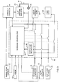
- FIG. 2 is a block diagram depicting components of the preferred embodiment.
- power supply 24 supplies electrical power required for the operation of components of instrument 6 including: touchscreen user interface 16, tourniquet controller 26, cuff pressure regulator 28, hazard suppressor 18, hazard suppression alarm 30, keypad controller 32 and pressure transducer 34.
- power supply 24 selectively supplies or interrupts the supply of electrical power to one or more components of instrument 6.
- Tourniquet controller 26 is a microcontroller typical of those known in the art with associated program and data memory, analog and digital peripheral interface circuitry, and other support components. Tourniquet controller 26 executes software programs that control the operation of instrument 6. For clarity, and to enable a better understanding of the principles of the invention some functions that may be performed by controller 26 are described and shown in FIG. 2 as separate functional blocks.
- Cuff 2 is pneumatically connected to pressure regulator 28 and pressure transducer 34 via cuff port 8, releasable locking connectors 10 and 12, tubing 14 and manifold 36.
- Pressure transducer 34 produces a cuff pressure signal that is indicative of the pressure of gas within the inflatable portion of cuff 2.
- the cuff pressure signal is communicated to pressure regulator 28 and hazard suppressor 18.
- pressure regulator 28 When supplied with electrical power from power supply 24, pressure regulator 28 can be directed by tourniquet controller 26 to maintain the pressure of gas within cuff 2 (cuff pressure) near a reference pressure level that is communicated to it by tourniquet controller 26. Pressure regulator 28 can also be directed by tourniquet controller 26 to depressurize cuff 2 to a pressure level near zero.
- pressure regulator 28 The electrical and pneumatic components of pressure regulator 28 are configured such that, when pressure regulator 28 is not supplied with electrical power from power supply 24, pressure regulator 28 does not permit any escape of gas from cuff 2 or provide any additional gas to cuff 2.
- Some tourniquet systems of the prior art act to depressurize an attached cuff when the power supply to components of the regulator is interrupted; this is unsafe because if power is removed from a regulator component at a time when surgery is in progress then unexpected blood flow may occur.
- Touchscreen user interface 16 is comprised of graphical display 38, backlight 40, light sensor 42, graphical controller 44, touchscreen 46 and touchscreen controller 48.
- Graphical display 38 is a color TFT LCD display panel with an LED or CCFL backlight. The backlight of graphical display 38 is identified in FIG. 2 as backlight 40.
- Light sensor 42 produces a signal indicative of the amount of light produced by graphical display 38 which is communicated to hazard suppressor 18.
- light sensor 42 is a light sensitive sensor such as a photodiode or phototransistor positioned in close proximity to backlight 40.
- light sensor 42 may comprise part of the circuitry used to supply power to backlight 40, allowing indirect determination of the amount of light produced by graphical display 38.
- Graphical display 38 may not require a backlight to display information that is visible to a user, by employing other technology such as OLED or plasma; light sensor 42 would then be adapted to directly or indirectly determine the amount of light produced by graphical display 38.
- the complete failure of backlight 40 makes any information displayed on graphical display 38 invisible to a user, and this is hazardous.
- a partial failure or reduction in the brightness of backlight 40 may make some information difficult to visually discern by the user in normal ambient lighting conditions, also presenting a hazard.
- Touchscreen 46 covers the display surface of graphical display 38.
- Touchscreen controller 48 determines the presence and location of a user's touch on touchscreen 46.
- touchscreen 46 and touchscreen controller 48 employ the principle of projected capacitance to determine the presence and location of a user's touch and are capable of determining the presence and location of multiple simultaneous touches by a user.
- a touchscreen employing other principles known in the art to discern the presence and location of a user's touch may be used, for example resistive, surface acoustic wave, and optical principles.
- Touchscreen controller 48 detects partial or complete malfunctions of its operation and malfunctions in the interface with touchscreen 46 as described below. When touchscreen controller 48 detects a malfunction it communicates a malfunction signal indicative of the detected malfunction to hazard suppressor 18.
- touchscreen controller 48 may detect one or more broken electrical connections with touchscreen 46 and communicate a malfunction signal to hazard suppressor 18 indicative of a region of touchscreen 46 in which a user's touch cannot be detected.
- Graphical controller 44 receives input from tourniquet controller 26 and operates to display images, icons, and text on graphical display 38. When graphical controller 44 detects an error in its operation that may result in incorrect or incomplete information being displayed on graphical display 38, it produces a malfunction signal that is communicated to hazard suppressor 18.
- a user of touchscreen interface 16 controls the operation of instrument 6 by touching the touchscreen in an area within the perimeter of a touchscreen key.
- touchscreen keys are icons and text shown on graphical display 38 that represent an action to be performed when the key is touched by a user.
- Each touchscreen key has a predetermined area and a predetermined perimeter and is shown at a selected location on graphical display 38. To initiate an action the user touches the touchscreen within the perimeter of the displayed icon or text.
- touchscreen 46 is constructed independently of underlying graphical display 38 and consequently touchscreen 46 indicates the presence and location of a user's touch within the perimeter of a displayed icon or text; at times when the icon or text may not be visible to the user due to a malfunction of the graphical controller 44 or backlight 40, a hazard exists.
- Keypad 50 comprises individual input keys 52, 54, and 56.
- Keypad controller 32 interfaces with keypad 50 and produces signals indicative of the keys touched by a user.
- Keypad 50 and keypad controller 32 operate independently of touchscreen user interface 16 and keypad 50 is located away from touchscreen user interface 16.
- keypad 50 and keypad controller 32 employ the principle of projected capacitance to detect key presses by a user. It will be apparent that alternatively other principles could be used to detect key presses by a user.
- Key 52 is a power control key and provides a means for a user to interrupt power to selected components of instrument 6.
- keys 54 and 56 provide a means for the user to enable or disable remote interface 20. Alternatively these discrete keys 52, 54 and 56 could be used to control other actions of instrument 6.
- keypad controller 32 When keypad controller 32 detects an error in its operation or a failure to communicate with keypad 50, it produces a malfunction signal that is communicated to hazard suppressor 18.
- FIG. 3 An operational schematic of hazard suppressor 18 is shown in FIG. 3 .
- Actions initiated by a user operating touchscreen user interface 16, keypad 50 and remote user interface 20 are communicated from touchscreen controller 48, keypad controller 32 and remote user interface 20 to tourniquet controller 26 through hazard suppressor 18.
- Keypad controller 32 also communicates with power supply 24 through hazard suppressor 18.
- Hazard suppressor 18 receives malfunction signals from light sensor 42, graphic controller 44, touchscreen controller 48 and keypad controller 32.
- Hazard suppressor 18 receives a cuff pressure signal indicative of the pressure in cuff 2 from pressure transducer 34.
- Hazard suppressor 18 monitors user-initiated actions input via touchscreen user interface 16, keypad 50 and remote user interface 20 to detect potentially hazardous user-initiated actions.
- hazard suppressor 18 includes logic 60 that uses the received levels of the malfunction signals and any detected hazardous user-initiated input action (58) to determine a hazard condition and, dependent upon the hazard condition and upon the difference between the actual cuff pressure and reference pressure level, selects which user-initiated action(s) to suppress, which to permit, and whether a confirming action may be required from the user before the desired action is communicated to tourniquet controller 26.
- hazard suppressor 18 produces a hazard suppression signal that is communicated to tourniquet controller 26 and also activates hazard suppression alarm 30 to alert the user that the desired action has been suppressed.
- hazard suppressor 18 receives a signal from light sensor 42 indicating that icons and text shown on graphical display 38 may not be visible to the user, then hazard suppressor 18 suppresses communication of user-initiated actions via touchscreen user interface 16 to tourniquet controller 26; a user-initiated action at a time when the graphical display 38 may not be producing visible information may result in undesired and hazardous changes in cuff pressure. If the cuff pressure level is near zero when this hazardous condition is detected, hazard suppressor 18 further suppresses communication from remote user interface 20; this prevents user-initiated actions that would pressurize cuff 2 from being communicated to tourniquet controller 26.
- hazard suppressor 18 receives a signal from light sensor 42 indicating that icons and text shown on graphical display 38 are not fully visible to a user (a partial failure of backlight 40), hazard suppressor 18 suppresses the communication of some user-initiated actions via touchscreen interface 16 to tourniquet controller 26: for example, if the cuff pressure level is near the reference pressure level, user-initiated actions that would change the reference pressure level are suppressed.
- hazard suppressor 18 monitors touchscreen controller 48 for user-initiated actions that are input via touchscreen user interface 16 ( FIG, 2 ), keypad controller 32 and remote user interface 20. This facilitates detection of potentially hazardous user actions (58). If such a detected potentially hazardous action would result in a change in cuff pressure or de-activation of an alarm, the user-requested action is suppressed by hazard suppressor 18.
- Touchscreen 46 and touchscreen controller 48 can detect the simultaneous presence of a user's touch at more than one location. When initiating some user actions via touchscreen user interface 16, a user may inadvertently touch more than one location simultaneously or may be required to touch more than one location simultaneously. The partial failure of touchscreen 46 or touchscreen controller 48 may result in false touches being reported by touchscreen controller 48.
- hazard suppressor 18 detects that a user has initiated an action by touching touchscreen 46 within the perimeter of a selected touchscreen key and a user's touch is also detected by touchscreen 46 at a location outside the perimeter of the selected touchscreen key, hazard suppressor 18 suppresses communication from touchscreen controller 48 to tourniquet controller 26 and the desired action initiated by the user is not communicated to tourniquet controller 26; additionally a hazard suppression signal is produced and hazard suppression alarm 30 is activated to alert the user that the desired action has been suppressed. Communication from touchscreen controller 48 remains suppressed and the hazard suppression signal remains active until touchscreen 46 no longer senses a user's touch at any location. User-initiated actions that are suppressed by hazard suppressor 18 are dependent upon the nature of the action being initiated by the user and the cuff pressure level.
- the preferred embodiment may require the user to touch two touchscreen keys at the same time. Also, if hazard suppressor 18 detects that the user has also touched the touchscreen at a location outside the perimeters of the two selected touchscreen keys and cuff 2 is pressurized, then hazard suppressor 18 suppresses communication from touchscreen controller 48 to tourniquet controller 26 and the desired action initiated by the user is not communicated to tourniquet controller 26; also a hazard suppression signal and hazard suppression alarm are produced to alert the user that the desired action has been suppressed. Communication from touchscreen controller 48 remains suppressed and the hazard suppression signal remains active until touchscreen 46 no longer senses a user's touch at any location (hence, there is no user input to communicate to the tourniquet controller).
- the preferred embodiment includes a power control key 52.
- Power control key 52 is interfaced with keypad controller 32 to produce a power control signal when key 52 is actuated; the power control signal is communicated through hazard suppressor 18 to power supply 24 and provides a means for a user to selectively interrupt power to components of instrument 6.
- Hazard suppressor 18 prevents communication of the power control signal from keypad controller 32 to power supply 24 at times when it would be unsafe to interrupt power to components of the preferred embodiment and also provides a means to override the suppression of the power control signal.
- hazard suppressor 18 suppresses communication of the power control signal, thereby preventing power supply 24 from interrupting the supply of power to pressure regulator 28, suppresses communication from touchscreen user interface 16, and activates hazard suppression alarm 30.
- hazard suppressor 18 monitors the power control signal from keypad controller 32 during the time that the malfunction is detected and communicates the power control signal to power supply 24 only if certain override conditions are met: in the preferred embodiment the override conditions are the continued activation of power key 52 by the user for longer than a predetermined time interval of 10 seconds, or the activation of power key 52 by the user at a first time and repeated actuation of power key 52 within a predetermined time interval of 5 seconds. It will be appreciated that other time intervals and sequences may be used by hazard suppressor 18 in determining when to override the power control signal.
- a user may set the level of pressure to be maintained in cuff 2 (reference pressure level) both via touchscreen user interface 16 and via remote user interface 20.
- reference pressure level level of pressure
- hazard suppressor 18 detects user-initiated actions input via touchscreen user interface 16 and remote user interface 20 that set the level of the reference pressure. If a user action would set the reference pressure level to a level that is significantly different from the cuff pressure sensed by pressure transducer 34, the action is suppressed and the hazard suppression alarm is activated.
- a significant difference between the cuff pressure and a desired reference pressure level is 50 mmHg for reference pressure levels set via touchscreen user interface 16 and 25 mmHg for reference pressure levels set via remote user interface 20.
- the desired reference pressure setting is suppressed; if the pressure in cuff 2 is 250 mmHg and a user-initiated action to set the reference pressure level to 300 mmHg via touchscreen user interface 16 is detected then the user-initiated action to set the reference pressure level to 300 mmHg is communicated to tourniquet controller 26.
- hazard suppressor 18 may be used by hazard suppressor 18. Moreover, the suppression may, in some instances, be overridden by a user's response to confirming input requested by the hazard suppressor 18.
- tourniquet controller 26 may be configured to adapt the cuff reference pressure level in response to changes in a physiologic parameter of the patient, in a manner similar to that described in U.S. App. Pub. No. 20080262533 , but with certain hazards suppressed: for example, a remote physiologic monitor for monitoring changes in a physiologic parameter of a patient may communicate with tourniquet controller 26 through hazard suppressor 18 so that, at times when a malfunction or input error is detected, communication is suppressed and tourniquet controller 26 is prevented from responding to monitored physiologic changes.
Landscapes
- Health & Medical Sciences (AREA)
- Life Sciences & Earth Sciences (AREA)
- Surgery (AREA)
- Engineering & Computer Science (AREA)
- Heart & Thoracic Surgery (AREA)
- Vascular Medicine (AREA)
- Nuclear Medicine, Radiotherapy & Molecular Imaging (AREA)
- Hematology (AREA)
- Biophysics (AREA)
- Biomedical Technology (AREA)
- Reproductive Health (AREA)
- Medical Informatics (AREA)
- Molecular Biology (AREA)
- Animal Behavior & Ethology (AREA)
- General Health & Medical Sciences (AREA)
- Public Health (AREA)
- Veterinary Medicine (AREA)
- Surgical Instruments (AREA)
- User Interface Of Digital Computer (AREA)
Claims (15)
- Chirurgisches Abbindungssystem aufweisend ein Gefahrenvermeidungssystem (18), umfassend:eine Touchscreen-Benutzeroberfläche (16) mit einer Grafikanzeige (38), die dafür ausgelegt ist, einem Benutzer Informationen visuell anzuzeigen, worin die Grafikanzeige (38) ferner dafür ausgelegt ist, eine Touchscreen-Taste zu zeigen, die einer gewünschten Funktion eines Abbindungssteuergerätes (26) entspricht, und worin die Touchscreen-Benutzeroberfläche (16) dafür ausgelegt ist, eine Betätigung der Touchscreen-Taste durch den Benutzer festzustellen, und dafür konfiguriert ist, nach Betätigung ein Benutzereingabesignal zu erzeugen;eine Abbindungsmanschette (2), die dafür ausgelegt ist, an einen chirurgischen Patienten angelegt zu werden;einen Manschettendruckregler (28);das Abbindungssteuergerät (26), worin das Abbindungssteuergerät dafür konfiguriert ist, mit der Touchscreen-Benutzeroberfläche (16) durch das Gefahrenvermeidungssystem (18) zu kommunizieren, und ferner dafür konfiguriert ist, mit dem Manschettendruckregler (28) zu kommunizieren, worin der Manschettendruckregler (28) pneumatisch mit der Abbindungsmanschette (2) verbunden ist;einen Manschettendruckaufnehmer (34) zum Erfassen eines Druckniveaus in der Abbindungsmanschette (2) und zum Erzeugen eines für das erfasste Druckniveau indikativen Manschettendrucksignals;worin das Gefahrenvermeidungssystem (18) dafür ausgelegt ist, eine Funktionsstörung der Touchscreen-Benutzeroberfläche (16) festzustellen, um einen Gefahrenzustand zu bestimmen, worin das Gefahrenvermeidungssystem (18) dafür konfiguriert ist, die Übermittlung des Benutzereingabesignals an das Abbindungssteuergerät (26) zu vermeiden, wenn der Gefahrenzustand festgestellt wird, undworin das Gefahrenvermeidungssystem (18) dafür konfiguriert ist, ferner ein Gefahrenvermeidungssignal zu erzeugen, wenn die Funktionsstörung festgestellt wird.
- System nach Anspruch 1, worin das Gefahrenvermeidungssystem (18) ferner dafür ausgelegt ist, einen gefährlichen benutzereingeleiteten Eingabevorgang (58) festzustellen.
- System nach Anspruch 1, worin die gewünschte Funktion eine Druckentlastung der Abbindungsmanschette (2) ist.
- System nach Anspruch 1, worin das Gefahrenvermeidungssystem (18) von der Touchscreen-Benutzeroberfläche (16) abgesetzt befindlich ist.
- System nach Anspruch 4, worin die Touchscreen-Benutzeroberfläche (16) dafür konfiguriert ist, drahtlos mit dem Abbindungssteuergerät (26) durch das Gefahrenvermeidungssystem (18) zu kommunizieren.
- System nach Anspruch 1, worin der Manschettendruckregler betreibbar ist, um den Abbindungsmanschettendruck während eines Zeitraums eines chirurgischen Eingriffs nahe einem Bezugsniveau zu halten, und das System ferner eine Remote-Vorrichtung beinhaltet, die unabhängig von der Touchscreen-Benutzeroberfläche betreibbar ist, um ein für ein für ein zweites Bezugsniveau indikatives Remote-Eingabesignal zu erzeugen, worin die Remote-Vorrichtung dafür konfiguriert ist, das Remote-Eingabesignal an das Abbindungssteuergerät durch das Gefahrenvermeidungssystem zu übermitteln, und worin das Gefahrenvermeidungssystem ferner dafür konfiguriert ist, die Übermittlung des Remote-Eingabesignals an das Abbindungssteuergerät zu vermeiden, wenn die Differenz zwischen dem Bezugsniveau und dem zweiten Bezugsniveau größer als eine vorbestimmte Differenz ist.
- System nach Anspruch 1 und mit einem Netzteil (24) zur Lieferung von elektrischem Strom an die Touchscreen-Benutzeroberfläche (16), das Gefahrenvermeidungssystem (18), das Abbindungssteuergerät (26) und den Manschettendruckregler (28) und worin, als Reaktion auf ein vom Gefahrenvermeidungssystem (18) entgegengenommenes Stromsteuerungssignal, das Netzteil (24) die Lieferung von elektrischem Strom an eine bzw. eines oder mehrere der Touchscreen-Benutzeroberfläche (16), des Gefahrenvermeidungssystems (18), des Abbindungssteuergerätes (26) und des Manschettendruckreglers (28) selektiv vornimmt oder unterbricht.
- System nach Anspruch 1, ferner beinhaltend einen Gefahrenvermeidungsalarm (30), der unabhängig von der Touchscreen-Benutzeroberfläche (16) betreibbar ist, um einen für den Benutzer wahrnehmbaren Gefahrenvermeidungsalarm (30) als Reaktion auf die Erzeugung des Gefahrenvermeidungssignals zu erzeugen.
- System nach Anspruch 1, worin die Touchscreen-Benutzeroberfläche (16) einen Lichtsensor (42) zum Erfassen eines von der Grafikanzeige (38) der Touchscreen-Benutzeroberfläche (16) erzeugten Lichtniveaus und zum Erzeugen eines für das erfasste Niveau indikativen Lichtniveausignals beinhaltet und worin das Gefahrenvermeidungssystem (18) dafür konfiguriert ist, einen Gefahrenzustand festzustellen, wenn das vom Lichtniveausignal indizierte Lichtniveau weniger als eine vorbestimmte Mindestlichtschwelle ist.
- System nach Anspruch 9, worin das Gefahrenvermeidungssystem (18) ferner dafür konfiguriert ist, einen Anzeige-Gefahrenalarm zu erzeugen, wenn das vom Lichtniveausignal indizierte Lichtniveau größer als die vorbestimmte Mindestschwelle und weniger als eine schwache Lichtschwelle ist, worin die schwache Lichtschwelle größer als die vorbestimmte Mindestschwelle ist.
- System nach Anspruch 1, worin die Grafikanzeige (38) der Touchscreen-Benutzeroberfläche (16) dafür konfiguriert ist, mit dem Abbindungssteuergerät (26) durch ein Grafikanzeige-Steuergerät (44) zu kommunizieren, worin das Grafikanzeige-Steuergerät (44) ferner dafür konfiguriert ist, ein Anzeigesteuergerät-Funktionsstörungssignal zu erzeugen, das für eine Funktionsstörung des Grafikanzeige-Steuergerätes (44) indikativ ist, und worin das Gefahrenvermeidungssystem (18) dafür konfiguriert ist, die Funktionsstörung der Touchscreen-Benutzeroberfläche (16) als Reaktion auf die Erzeugung des Anzeigesteuergerät-Funktionsstörungssignals festzustellen.
- System nach Anspruch 1, worin die Touchscreen-Taste dafür konfiguriert ist, ein die gewünschte Funktion des Abbindungssteuergerätes (26) repräsentierendes Symbol anzuzeigen.
- Verfahren zum Vermeiden einer Gefahr in einem chirurgischem Abbindungssystem umfassend eine Abbindungsmanschette (2), die dafür ausgelegt ist, an einen chirurgischen Patienten angelegt zu werden, und ein Abbindungssteuergerät (26), das mit einem Manschettendruckregler (28) kommuniziert, worin der Manschettendruckregler (28) pneumatisch mit der Abbindungsmanschette (2) verbunden ist, und einen Manschettendruckaufnehmer (34) zum Erfassen eines Druckniveaus in der Abbindungsmanschette (2) und zum Erzeugen eines für das erfasste Druckniveau indikativen Manschettendrucksignals, wobei das Verfahren die folgenden Schritte umfasst:visuelles Anzeigen für einen Benutzer, auf einer Grafikanzeige (38) einer Touchscreen-Benutzeroberfläche (16), einer Touchscreen-Taste, die einer gewünschten Funktion eines Abbindungssteuergerätes (26) entspricht;Feststellen, durch die Touchscreen-Benutzeroberfläche (16), einer Betätigung der Touchscreen-Taste durch den Benutzer und Erzeugen eines Benutzereingabesignals nach Betätigung;Kommunizieren, durch das Abbindungssteuergerät (26), mit der Touchscreen-Benutzeroberfläche (16) durch ein Gefahrenvermeidungssystem (18); undFeststellen, durch das Gefahrenvermeidungssystem (18), einer Funktionsstörung der Touchscreen-Benutzeroberfläche (16), um einen Gefahrenzustand zu bestimmen, worin das Gefahrenvermeidungssystem (18) die Übermittlung des Benutzereingabesignals an das Abbindungssteuergerät (26) vermeidet, wenn der Gefahrenzustand festgestellt wird.
- Verfahren nach Anspruch 13, worin der Anzeigeschritt das visuelle Anzeigen, für den Benutzer, der Touchscreen-Taste beinhaltet, die der gewünschten Funktion des Druckentlastens der Abbindungsmanschette (2) entspricht.
- Verfahren nach Anspruch 13, worin, als Reaktion auf ein vom Gefahrenvermeidungssystem (18) entgegengenommenes Stromsteuerungssignal, das Verfahren ferner den Schritt des selektiven Lieferns oder Unterbrechens einer elektrischen Stromversorgung an eine bzw. eines oder mehrere der Touchscreen-Benutzeroberfläche (16), des Gefahrenvermeidungssystems (18), des Abbindungssteuergerätes (26) und des Manschettendruckreglers (28) umfasst.
Applications Claiming Priority (2)
| Application Number | Priority Date | Filing Date | Title |
|---|---|---|---|
| US36707910P | 2010-07-23 | 2010-07-23 | |
| PCT/CA2011/000782 WO2012009787A1 (en) | 2010-07-23 | 2011-07-04 | Tourniquet hazard suppressor |
Publications (3)
| Publication Number | Publication Date |
|---|---|
| EP2595550A1 EP2595550A1 (de) | 2013-05-29 |
| EP2595550A4 EP2595550A4 (de) | 2015-05-20 |
| EP2595550B1 true EP2595550B1 (de) | 2018-06-20 |
Family
ID=45496399
Family Applications (1)
| Application Number | Title | Priority Date | Filing Date |
|---|---|---|---|
| EP11809101.6A Active EP2595550B1 (de) | 2010-07-23 | 2011-07-04 | Gefahrenvermeidungssystem für eine abbindungsvorrichtung |
Country Status (5)
| Country | Link |
|---|---|
| US (1) | US9138236B2 (de) |
| EP (1) | EP2595550B1 (de) |
| AU (1) | AU2011282420B2 (de) |
| CA (1) | CA2805880C (de) |
| WO (1) | WO2012009787A1 (de) |
Families Citing this family (13)
| Publication number | Priority date | Publication date | Assignee | Title |
|---|---|---|---|---|
| US9814467B2 (en) | 2014-07-10 | 2017-11-14 | Western Clinical Engineering Ltd. | Personalized tourniquet apparatus |
| US9039730B1 (en) | 2014-07-10 | 2015-05-26 | Western Clinical Engineering, Ltd. | Personalized tourniquet system having dual-purpose cuff |
| US9931126B2 (en) | 2014-07-10 | 2018-04-03 | Western Clinical Engineering Ltd. | Personalized tourniquet methods and apparatus |
| USRE50013E1 (en) | 2014-07-25 | 2024-06-18 | Western Clinical Engineering Ltd. | Tourniquet system for personalized restriction of blood flow |
| US9877733B1 (en) * | 2014-09-12 | 2018-01-30 | Mohammad R. Jafary | Anti-necrosis tourniquet device |
| WO2017023619A1 (en) | 2015-07-31 | 2017-02-09 | Carabajal Johnny | Wearable emergency hemorrhage cessation systems |
| US10136903B2 (en) | 2016-03-28 | 2018-11-27 | Patrick James LYNCH | Tourniquet and method thereof having compliance logging and alert features, and a system thereof |
| CN105726083A (zh) * | 2016-04-22 | 2016-07-06 | 深圳市前海康启源科技有限公司 | 气压式自动止血设备及方法 |
| CN106618668A (zh) * | 2017-01-23 | 2017-05-10 | 中国人民解放军第二军医大学 | 一种股动脉压迫止血装置 |
| CN112040888B (zh) | 2018-03-05 | 2024-03-08 | 西方医疗工程有限公司 | 用于间歇性血管闭塞的个性化止血带 |
| US11944322B2 (en) * | 2018-06-22 | 2024-04-02 | Western Clinical Engineering Ltd. | Tourniquet with user-selectable safety protocols |
| US11723670B2 (en) * | 2021-03-16 | 2023-08-15 | Western Clinical Engineering Ltd. | Automatic tourniquet apparatus having patient hazard shield |
| US20230240689A1 (en) * | 2022-01-28 | 2023-08-03 | Ingenio Technology Co., Limited | Automatic unlock device for tourniquet |
Family Cites Families (24)
| Publication number | Priority date | Publication date | Assignee | Title |
|---|---|---|---|---|
| GB1275083A (en) * | 1969-07-23 | 1972-05-24 | Jobst Institute | Tourniquet apparatus |
| US4469099A (en) * | 1980-10-02 | 1984-09-04 | Western Clinical Engineering Ltd. | Pneumatic torniquet |
| US4479494A (en) * | 1982-01-05 | 1984-10-30 | Western Clinical Engineering Ltd. | Adaptive pneumatic tourniquet |
| US4635635A (en) | 1984-11-29 | 1987-01-13 | Aspen Laboratories, Inc. | Tourniquet cuff |
| US5556415A (en) | 1990-01-29 | 1996-09-17 | Mcewen; James A. | Physiologic tourniquet for intravenous regional anesthesia |
| US5607447A (en) | 1993-09-28 | 1997-03-04 | Mcewen; James A. | Physiologic tourniquet |
| US5741295A (en) | 1991-09-30 | 1998-04-21 | James A. McEwen | Overlapping tourniquet cuff system |
| US5649954A (en) | 1991-09-30 | 1997-07-22 | Mcewen; James A. | Tourniquet cuff system |
| US5855589A (en) | 1995-08-25 | 1999-01-05 | Mcewen; James A. | Physiologic tourniquet for intravenous regional anesthesia |
| US5931853A (en) * | 1995-08-25 | 1999-08-03 | Mcewen; James A. | Physiologic tourniquet with safety circuit |
| US6736787B1 (en) * | 1996-04-29 | 2004-05-18 | Mcewen James Allen | Apparatus for applying pressure waveforms to a limb |
| US5968073A (en) * | 1997-11-17 | 1999-10-19 | Jacobs; Laura F. | Methods and apparatus for applying pressure |
| US6589268B1 (en) * | 1998-12-10 | 2003-07-08 | Mcewen James A. | Hazard monitor for surgical tourniquet systems |
| US6213939B1 (en) | 1998-12-10 | 2001-04-10 | Mcewen James Allen | Hazard monitor for surgical tourniquet systems |
| US7485131B2 (en) * | 1999-03-29 | 2009-02-03 | Stryker Corporation | System and method for controlling pressure in a surgical tourniquet |
| US6051016A (en) * | 1999-03-29 | 2000-04-18 | Instrumed, Inc. | System and method of controlling pressure in a surgical tourniquet |
| US7166123B2 (en) * | 1999-03-29 | 2007-01-23 | Instrumed | System and method for controlling pressure in a surgical tourniquet using a remote unit |
| US7048702B2 (en) * | 2002-06-13 | 2006-05-23 | Vasomedical, Inc. | External counterpulsation and method for minimizing end diastolic pressure |
| US20080009680A1 (en) * | 2005-06-24 | 2008-01-10 | Hassler William L Jr | Remote monitoring and adjustment of a food intake restriction device |
| US7479154B2 (en) * | 2005-05-05 | 2009-01-20 | Mcewen James A | Surgical tourniquet apparatus for measuring limb occlusion pressure |
| US7955352B2 (en) * | 2005-08-05 | 2011-06-07 | Western Clinical Engineering, Ltd | Surgical tourniquet cuff for limiting usage to improve safety |
| US8048105B2 (en) * | 2007-04-19 | 2011-11-01 | Western Clinical Engineering Ltd. | Adaptive surgical tourniquet apparatus and method |
| US8425426B2 (en) * | 2007-11-09 | 2013-04-23 | Western Clinical Engineering, Ltd | Tourniquet apparatus for measuring limb occlusion pressure |
| US9113895B2 (en) * | 2009-02-19 | 2015-08-25 | Western Clinical Engineering Ltd. | Integrated tourniquet system |
-
2011
- 2011-07-04 WO PCT/CA2011/000782 patent/WO2012009787A1/en not_active Ceased
- 2011-07-04 CA CA2805880A patent/CA2805880C/en active Active
- 2011-07-04 AU AU2011282420A patent/AU2011282420B2/en active Active
- 2011-07-04 US US13/811,309 patent/US9138236B2/en active Active
- 2011-07-04 EP EP11809101.6A patent/EP2595550B1/de active Active
Non-Patent Citations (1)
| Title |
|---|
| None * |
Also Published As
| Publication number | Publication date |
|---|---|
| CA2805880C (en) | 2017-04-11 |
| CA2805880A1 (en) | 2012-01-26 |
| US9138236B2 (en) | 2015-09-22 |
| EP2595550A4 (de) | 2015-05-20 |
| AU2011282420A1 (en) | 2013-02-28 |
| US20130211445A1 (en) | 2013-08-15 |
| AU2011282420B2 (en) | 2014-11-06 |
| EP2595550A1 (de) | 2013-05-29 |
| WO2012009787A1 (en) | 2012-01-26 |
Similar Documents
| Publication | Publication Date | Title |
|---|---|---|
| US9138236B2 (en) | Tourniquet hazard suppressor | |
| EP1879510B1 (de) | Okklusionsdetektor für chirurgische dual-port-tourniquet-systeme | |
| EP2398403B1 (de) | Integriertes abbindesystem | |
| AU762365B2 (en) | Hazard monitor for surgical tourniquet systems | |
| EP2395928B1 (de) | Vorrichtung zur leckagebeurteilung bei einem chirurgischen tourniquet-system | |
| US6589268B1 (en) | Hazard monitor for surgical tourniquet systems | |
| EP3809984B1 (de) | Tourniquet mit benutzerwählbaren sicherheitsprotokollen |
Legal Events
| Date | Code | Title | Description |
|---|---|---|---|
| PUAI | Public reference made under article 153(3) epc to a published international application that has entered the european phase |
Free format text: ORIGINAL CODE: 0009012 |
|
| 17P | Request for examination filed |
Effective date: 20130213 |
|
| AK | Designated contracting states |
Kind code of ref document: A1 Designated state(s): AL AT BE BG CH CY CZ DE DK EE ES FI FR GB GR HR HU IE IS IT LI LT LU LV MC MK MT NL NO PL PT RO RS SE SI SK SM TR |
|
| DAX | Request for extension of the european patent (deleted) | ||
| RA4 | Supplementary search report drawn up and despatched (corrected) |
Effective date: 20150422 |
|
| RIC1 | Information provided on ipc code assigned before grant |
Ipc: A61B 17/135 20060101AFI20150416BHEP |
|
| 17Q | First examination report despatched |
Effective date: 20150826 |
|
| GRAP | Despatch of communication of intention to grant a patent |
Free format text: ORIGINAL CODE: EPIDOSNIGR1 |
|
| INTG | Intention to grant announced |
Effective date: 20170413 |
|
| GRAJ | Information related to disapproval of communication of intention to grant by the applicant or resumption of examination proceedings by the epo deleted |
Free format text: ORIGINAL CODE: EPIDOSDIGR1 |
|
| INTC | Intention to grant announced (deleted) | ||
| GRAP | Despatch of communication of intention to grant a patent |
Free format text: ORIGINAL CODE: EPIDOSNIGR1 |
|
| INTG | Intention to grant announced |
Effective date: 20180302 |
|
| GRAS | Grant fee paid |
Free format text: ORIGINAL CODE: EPIDOSNIGR3 |
|
| GRAA | (expected) grant |
Free format text: ORIGINAL CODE: 0009210 |
|
| AK | Designated contracting states |
Kind code of ref document: B1 Designated state(s): AL AT BE BG CH CY CZ DE DK EE ES FI FR GB GR HR HU IE IS IT LI LT LU LV MC MK MT NL NO PL PT RO RS SE SI SK SM TR |
|
| REG | Reference to a national code |
Ref country code: GB Ref legal event code: FG4D |
|
| REG | Reference to a national code |
Ref country code: IE Ref legal event code: FG4D |
|
| REG | Reference to a national code |
Ref country code: DE Ref legal event code: R096 Ref document number: 602011049447 Country of ref document: DE Ref country code: FR Ref legal event code: PLFP Year of fee payment: 8 |
|
| REG | Reference to a national code |
Ref country code: AT Ref legal event code: REF Ref document number: 1010007 Country of ref document: AT Kind code of ref document: T Effective date: 20180715 |
|
| REG | Reference to a national code |
Ref country code: NL Ref legal event code: MP Effective date: 20180620 |
|
| PG25 | Lapsed in a contracting state [announced via postgrant information from national office to epo] |
Ref country code: SE Free format text: LAPSE BECAUSE OF FAILURE TO SUBMIT A TRANSLATION OF THE DESCRIPTION OR TO PAY THE FEE WITHIN THE PRESCRIBED TIME-LIMIT Effective date: 20180620 Ref country code: BG Free format text: LAPSE BECAUSE OF FAILURE TO SUBMIT A TRANSLATION OF THE DESCRIPTION OR TO PAY THE FEE WITHIN THE PRESCRIBED TIME-LIMIT Effective date: 20180920 Ref country code: NO Free format text: LAPSE BECAUSE OF FAILURE TO SUBMIT A TRANSLATION OF THE DESCRIPTION OR TO PAY THE FEE WITHIN THE PRESCRIBED TIME-LIMIT Effective date: 20180920 Ref country code: FI Free format text: LAPSE BECAUSE OF FAILURE TO SUBMIT A TRANSLATION OF THE DESCRIPTION OR TO PAY THE FEE WITHIN THE PRESCRIBED TIME-LIMIT Effective date: 20180620 Ref country code: LT Free format text: LAPSE BECAUSE OF FAILURE TO SUBMIT A TRANSLATION OF THE DESCRIPTION OR TO PAY THE FEE WITHIN THE PRESCRIBED TIME-LIMIT Effective date: 20180620 |
|
| REG | Reference to a national code |
Ref country code: LT Ref legal event code: MG4D |
|
| PG25 | Lapsed in a contracting state [announced via postgrant information from national office to epo] |
Ref country code: GR Free format text: LAPSE BECAUSE OF FAILURE TO SUBMIT A TRANSLATION OF THE DESCRIPTION OR TO PAY THE FEE WITHIN THE PRESCRIBED TIME-LIMIT Effective date: 20180921 Ref country code: HR Free format text: LAPSE BECAUSE OF FAILURE TO SUBMIT A TRANSLATION OF THE DESCRIPTION OR TO PAY THE FEE WITHIN THE PRESCRIBED TIME-LIMIT Effective date: 20180620 Ref country code: LV Free format text: LAPSE BECAUSE OF FAILURE TO SUBMIT A TRANSLATION OF THE DESCRIPTION OR TO PAY THE FEE WITHIN THE PRESCRIBED TIME-LIMIT Effective date: 20180620 Ref country code: RS Free format text: LAPSE BECAUSE OF FAILURE TO SUBMIT A TRANSLATION OF THE DESCRIPTION OR TO PAY THE FEE WITHIN THE PRESCRIBED TIME-LIMIT Effective date: 20180620 |
|
| REG | Reference to a national code |
Ref country code: AT Ref legal event code: MK05 Ref document number: 1010007 Country of ref document: AT Kind code of ref document: T Effective date: 20180620 |
|
| PG25 | Lapsed in a contracting state [announced via postgrant information from national office to epo] |
Ref country code: NL Free format text: LAPSE BECAUSE OF FAILURE TO SUBMIT A TRANSLATION OF THE DESCRIPTION OR TO PAY THE FEE WITHIN THE PRESCRIBED TIME-LIMIT Effective date: 20180620 |
|
| PG25 | Lapsed in a contracting state [announced via postgrant information from national office to epo] |
Ref country code: RO Free format text: LAPSE BECAUSE OF FAILURE TO SUBMIT A TRANSLATION OF THE DESCRIPTION OR TO PAY THE FEE WITHIN THE PRESCRIBED TIME-LIMIT Effective date: 20180620 Ref country code: SK Free format text: LAPSE BECAUSE OF FAILURE TO SUBMIT A TRANSLATION OF THE DESCRIPTION OR TO PAY THE FEE WITHIN THE PRESCRIBED TIME-LIMIT Effective date: 20180620 Ref country code: CZ Free format text: LAPSE BECAUSE OF FAILURE TO SUBMIT A TRANSLATION OF THE DESCRIPTION OR TO PAY THE FEE WITHIN THE PRESCRIBED TIME-LIMIT Effective date: 20180620 Ref country code: EE Free format text: LAPSE BECAUSE OF FAILURE TO SUBMIT A TRANSLATION OF THE DESCRIPTION OR TO PAY THE FEE WITHIN THE PRESCRIBED TIME-LIMIT Effective date: 20180620 Ref country code: IS Free format text: LAPSE BECAUSE OF FAILURE TO SUBMIT A TRANSLATION OF THE DESCRIPTION OR TO PAY THE FEE WITHIN THE PRESCRIBED TIME-LIMIT Effective date: 20181020 Ref country code: AT Free format text: LAPSE BECAUSE OF FAILURE TO SUBMIT A TRANSLATION OF THE DESCRIPTION OR TO PAY THE FEE WITHIN THE PRESCRIBED TIME-LIMIT Effective date: 20180620 Ref country code: PL Free format text: LAPSE BECAUSE OF FAILURE TO SUBMIT A TRANSLATION OF THE DESCRIPTION OR TO PAY THE FEE WITHIN THE PRESCRIBED TIME-LIMIT Effective date: 20180620 |
|
| PG25 | Lapsed in a contracting state [announced via postgrant information from national office to epo] |
Ref country code: IT Free format text: LAPSE BECAUSE OF FAILURE TO SUBMIT A TRANSLATION OF THE DESCRIPTION OR TO PAY THE FEE WITHIN THE PRESCRIBED TIME-LIMIT Effective date: 20180620 Ref country code: SM Free format text: LAPSE BECAUSE OF FAILURE TO SUBMIT A TRANSLATION OF THE DESCRIPTION OR TO PAY THE FEE WITHIN THE PRESCRIBED TIME-LIMIT Effective date: 20180620 Ref country code: ES Free format text: LAPSE BECAUSE OF FAILURE TO SUBMIT A TRANSLATION OF THE DESCRIPTION OR TO PAY THE FEE WITHIN THE PRESCRIBED TIME-LIMIT Effective date: 20180620 |
|
| REG | Reference to a national code |
Ref country code: CH Ref legal event code: PL |
|
| REG | Reference to a national code |
Ref country code: DE Ref legal event code: R097 Ref document number: 602011049447 Country of ref document: DE |
|
| PG25 | Lapsed in a contracting state [announced via postgrant information from national office to epo] |
Ref country code: MC Free format text: LAPSE BECAUSE OF FAILURE TO SUBMIT A TRANSLATION OF THE DESCRIPTION OR TO PAY THE FEE WITHIN THE PRESCRIBED TIME-LIMIT Effective date: 20180620 Ref country code: LU Free format text: LAPSE BECAUSE OF NON-PAYMENT OF DUE FEES Effective date: 20180704 |
|
| REG | Reference to a national code |
Ref country code: BE Ref legal event code: MM Effective date: 20180731 |
|
| REG | Reference to a national code |
Ref country code: IE Ref legal event code: MM4A |
|
| PLBE | No opposition filed within time limit |
Free format text: ORIGINAL CODE: 0009261 |
|
| STAA | Information on the status of an ep patent application or granted ep patent |
Free format text: STATUS: NO OPPOSITION FILED WITHIN TIME LIMIT |
|
| PG25 | Lapsed in a contracting state [announced via postgrant information from national office to epo] |
Ref country code: CH Free format text: LAPSE BECAUSE OF NON-PAYMENT OF DUE FEES Effective date: 20180731 Ref country code: IE Free format text: LAPSE BECAUSE OF NON-PAYMENT OF DUE FEES Effective date: 20180704 Ref country code: LI Free format text: LAPSE BECAUSE OF NON-PAYMENT OF DUE FEES Effective date: 20180731 |
|
| 26N | No opposition filed |
Effective date: 20190321 |
|
| PG25 | Lapsed in a contracting state [announced via postgrant information from national office to epo] |
Ref country code: BE Free format text: LAPSE BECAUSE OF NON-PAYMENT OF DUE FEES Effective date: 20180731 Ref country code: DK Free format text: LAPSE BECAUSE OF FAILURE TO SUBMIT A TRANSLATION OF THE DESCRIPTION OR TO PAY THE FEE WITHIN THE PRESCRIBED TIME-LIMIT Effective date: 20180620 |
|
| PG25 | Lapsed in a contracting state [announced via postgrant information from national office to epo] |
Ref country code: SI Free format text: LAPSE BECAUSE OF FAILURE TO SUBMIT A TRANSLATION OF THE DESCRIPTION OR TO PAY THE FEE WITHIN THE PRESCRIBED TIME-LIMIT Effective date: 20180620 |
|
| PG25 | Lapsed in a contracting state [announced via postgrant information from national office to epo] |
Ref country code: AL Free format text: LAPSE BECAUSE OF FAILURE TO SUBMIT A TRANSLATION OF THE DESCRIPTION OR TO PAY THE FEE WITHIN THE PRESCRIBED TIME-LIMIT Effective date: 20180620 |
|
| PG25 | Lapsed in a contracting state [announced via postgrant information from national office to epo] |
Ref country code: MT Free format text: LAPSE BECAUSE OF NON-PAYMENT OF DUE FEES Effective date: 20180704 |
|
| PG25 | Lapsed in a contracting state [announced via postgrant information from national office to epo] |
Ref country code: TR Free format text: LAPSE BECAUSE OF FAILURE TO SUBMIT A TRANSLATION OF THE DESCRIPTION OR TO PAY THE FEE WITHIN THE PRESCRIBED TIME-LIMIT Effective date: 20180620 |
|
| PG25 | Lapsed in a contracting state [announced via postgrant information from national office to epo] |
Ref country code: PT Free format text: LAPSE BECAUSE OF FAILURE TO SUBMIT A TRANSLATION OF THE DESCRIPTION OR TO PAY THE FEE WITHIN THE PRESCRIBED TIME-LIMIT Effective date: 20180620 Ref country code: HU Free format text: LAPSE BECAUSE OF FAILURE TO SUBMIT A TRANSLATION OF THE DESCRIPTION OR TO PAY THE FEE WITHIN THE PRESCRIBED TIME-LIMIT; INVALID AB INITIO Effective date: 20110704 |
|
| PG25 | Lapsed in a contracting state [announced via postgrant information from national office to epo] |
Ref country code: CY Free format text: LAPSE BECAUSE OF FAILURE TO SUBMIT A TRANSLATION OF THE DESCRIPTION OR TO PAY THE FEE WITHIN THE PRESCRIBED TIME-LIMIT Effective date: 20180620 Ref country code: MK Free format text: LAPSE BECAUSE OF NON-PAYMENT OF DUE FEES Effective date: 20180620 |
|
| P01 | Opt-out of the competence of the unified patent court (upc) registered |
Effective date: 20230506 |
|
| PGFP | Annual fee paid to national office [announced via postgrant information from national office to epo] |
Ref country code: GB Payment date: 20250605 Year of fee payment: 15 |
|
| PGFP | Annual fee paid to national office [announced via postgrant information from national office to epo] |
Ref country code: FR Payment date: 20250610 Year of fee payment: 15 |
|
| PGFP | Annual fee paid to national office [announced via postgrant information from national office to epo] |
Ref country code: DE Payment date: 20250604 Year of fee payment: 15 |