EP2395928B1 - Vorrichtung zur leckagebeurteilung bei einem chirurgischen tourniquet-system - Google Patents
Vorrichtung zur leckagebeurteilung bei einem chirurgischen tourniquet-system Download PDFInfo
- Publication number
- EP2395928B1 EP2395928B1 EP10740867.6A EP10740867A EP2395928B1 EP 2395928 B1 EP2395928 B1 EP 2395928B1 EP 10740867 A EP10740867 A EP 10740867A EP 2395928 B1 EP2395928 B1 EP 2395928B1
- Authority
- EP
- European Patent Office
- Prior art keywords
- cuff
- pressure
- leakage
- magnitude
- pressure regulator
- Prior art date
- Legal status (The legal status is an assumption and is not a legal conclusion. Google has not performed a legal analysis and makes no representation as to the accuracy of the status listed.)
- Active
Links
- 230000007423 decrease Effects 0.000 claims description 17
- 238000012544 monitoring process Methods 0.000 claims description 9
- 230000004044 response Effects 0.000 claims description 6
- 238000004891 communication Methods 0.000 claims description 5
- 230000001052 transient effect Effects 0.000 claims description 3
- 238000013022 venting Methods 0.000 claims 1
- 239000007789 gas Substances 0.000 description 34
- 238000001356 surgical procedure Methods 0.000 description 10
- 230000002459 sustained effect Effects 0.000 description 7
- 230000033228 biological regulation Effects 0.000 description 6
- 230000006378 damage Effects 0.000 description 6
- 231100001261 hazardous Toxicity 0.000 description 6
- 239000008280 blood Substances 0.000 description 5
- 210000004369 blood Anatomy 0.000 description 5
- 230000006870 function Effects 0.000 description 5
- 208000027418 Wounds and injury Diseases 0.000 description 4
- 238000001514 detection method Methods 0.000 description 4
- 208000014674 injury Diseases 0.000 description 4
- 230000007547 defect Effects 0.000 description 3
- 238000000034 method Methods 0.000 description 3
- 230000000246 remedial effect Effects 0.000 description 3
- 230000009471 action Effects 0.000 description 2
- 230000004913 activation Effects 0.000 description 2
- 230000017531 blood circulation Effects 0.000 description 2
- 230000008859 change Effects 0.000 description 2
- 238000004140 cleaning Methods 0.000 description 2
- 230000003247 decreasing effect Effects 0.000 description 2
- 230000002950 deficient Effects 0.000 description 2
- 238000010586 diagram Methods 0.000 description 2
- 229920002457 flexible plastic Polymers 0.000 description 2
- 239000000463 material Substances 0.000 description 2
- 230000009467 reduction Effects 0.000 description 2
- 230000001105 regulatory effect Effects 0.000 description 2
- 238000012958 reprocessing Methods 0.000 description 2
- 238000004659 sterilization and disinfection Methods 0.000 description 2
- 230000002411 adverse Effects 0.000 description 1
- 230000008321 arterial blood flow Effects 0.000 description 1
- 238000010276 construction Methods 0.000 description 1
- 230000001276 controlling effect Effects 0.000 description 1
- 239000004744 fabric Substances 0.000 description 1
- 239000012530 fluid Substances 0.000 description 1
- 230000001771 impaired effect Effects 0.000 description 1
- 230000036512 infertility Effects 0.000 description 1
- 238000007689 inspection Methods 0.000 description 1
- 238000001990 intravenous administration Methods 0.000 description 1
- 238000004519 manufacturing process Methods 0.000 description 1
- 230000000116 mitigating effect Effects 0.000 description 1
- 210000005036 nerve Anatomy 0.000 description 1
- 230000002093 peripheral effect Effects 0.000 description 1
- 229920003023 plastic Polymers 0.000 description 1
- 230000002035 prolonged effect Effects 0.000 description 1
- 238000002694 regional anesthesia Methods 0.000 description 1
- 230000008439 repair process Effects 0.000 description 1
- 210000004872 soft tissue Anatomy 0.000 description 1
- 230000001954 sterilising effect Effects 0.000 description 1
- 210000001519 tissue Anatomy 0.000 description 1
- 230000009495 transient activation Effects 0.000 description 1
- 230000000007 visual effect Effects 0.000 description 1
Images

Classifications
-
- A—HUMAN NECESSITIES
- A61—MEDICAL OR VETERINARY SCIENCE; HYGIENE
- A61B—DIAGNOSIS; SURGERY; IDENTIFICATION
- A61B17/00—Surgical instruments, devices or methods
- A61B17/12—Surgical instruments, devices or methods for ligaturing or otherwise compressing tubular parts of the body, e.g. blood vessels or umbilical cord
- A61B17/132—Tourniquets
- A61B17/135—Tourniquets inflatable
- A61B17/1355—Automated control means therefor
-
- A—HUMAN NECESSITIES
- A61—MEDICAL OR VETERINARY SCIENCE; HYGIENE
- A61B—DIAGNOSIS; SURGERY; IDENTIFICATION
- A61B17/00—Surgical instruments, devices or methods
- A61B2017/00017—Electrical control of surgical instruments
- A61B2017/00115—Electrical control of surgical instruments with audible or visual output
- A61B2017/00119—Electrical control of surgical instruments with audible or visual output alarm; indicating an abnormal situation
-
- A—HUMAN NECESSITIES
- A61—MEDICAL OR VETERINARY SCIENCE; HYGIENE
- A61B—DIAGNOSIS; SURGERY; IDENTIFICATION
- A61B17/00—Surgical instruments, devices or methods
- A61B2017/00017—Electrical control of surgical instruments
- A61B2017/00132—Setting operation time of a device
-
- A—HUMAN NECESSITIES
- A61—MEDICAL OR VETERINARY SCIENCE; HYGIENE
- A61B—DIAGNOSIS; SURGERY; IDENTIFICATION
- A61B17/00—Surgical instruments, devices or methods
- A61B2017/00017—Electrical control of surgical instruments
- A61B2017/00199—Electrical control of surgical instruments with a console, e.g. a control panel with a display
-
- A—HUMAN NECESSITIES
- A61—MEDICAL OR VETERINARY SCIENCE; HYGIENE
- A61B—DIAGNOSIS; SURGERY; IDENTIFICATION
- A61B90/00—Instruments, implements or accessories specially adapted for surgery or diagnosis and not covered by any of the groups A61B1/00 - A61B50/00, e.g. for luxation treatment or for protecting wound edges
- A61B90/06—Measuring instruments not otherwise provided for
- A61B2090/064—Measuring instruments not otherwise provided for for measuring force, pressure or mechanical tension
-
- A—HUMAN NECESSITIES
- A61—MEDICAL OR VETERINARY SCIENCE; HYGIENE
- A61B—DIAGNOSIS; SURGERY; IDENTIFICATION
- A61B90/00—Instruments, implements or accessories specially adapted for surgery or diagnosis and not covered by any of the groups A61B1/00 - A61B50/00, e.g. for luxation treatment or for protecting wound edges
- A61B90/08—Accessories or related features not otherwise provided for
- A61B2090/0807—Indication means
- A61B2090/0809—Indication of cracks or breakages
Definitions
- This invention pertains to pneumatic tourniquet systems commonly used for stopping the flow of arterial blood into a portion of a surgical patient's limb to facilitate the performance of a surgical procedure and for facilitating intravenous regional anesthesia.
- Surgical tourniquet systems are commonly used to stop the flow of arterial blood into a portion of a patient's limb, thus creating a clear, dry surgical field that facilitates the performance of a surgical procedure and improves outcomes.
- a typical surgical tourniquet system of the prior art includes a tourniquet cuff for encircling a patient's limb at a desired location, a tourniquet instrument, and flexible pneumatic tubing connecting the cuff to the instrument.
- the tourniquet cuff includes an inflatable portion, and the inflatable portion of the cuff is connected pneumatically through flexible plastic tubing and one or more connectors to a tourniquet instrument.
- a typical tourniquet instrument of the prior art includes a pressure regulator to maintain the pressure in the inflatable portion of the cuff, when applied to a patient's limb at a desired location, near a reference pressure that is above a minimum pressure required to stop arterial blood flow past the cuff during a time period suitably long for the performance of a surgical procedure.
- Many types of such pneumatic surgical tourniquet systems have been described in the prior art, such as those described by McEwen in U.S. Patent No. 4,469,099 , No. 4,479,494 , No. 5,439,477 and by McEwen and Jameson in U.S. Pat. No. 5,556,415 and No. 5,855,589 .
- the AORN RPs further recommend, based on published literature, that the tourniquet cuff, tubing, and connectors should be inspected for cracks and leaks because unintentional pressure loss can result from loose tubing connectors, deteriorated tubing, or cuff bladder leaks, and may result in patient injury.
- inspections and checking are performed manually and often inconsistently by users, or only after a hazardous incident or patient injury has occurred.
- defective and leaking tourniquet cuffs, connectors and tubing may remain in use for long periods of time.
- users may not be alerted to defects which may be small initially but which may increase to become significant hazards, either slowly or very rapidly, if remedial action is not taken.
- some surgical tourniquet systems of the prior art include audio-visual leakage alarms.
- alarms in prior-art systems are typically produced only after there has been a decrease in actual cuff pressure to a level that is well below the reference pressure for a sustained period of time, and thus only after substantial blood flow past the cuff may have occurred. This adversely affects the safety and quality of surgery before the user is alerted to the need for remedial action.
- the pressure regulator is designed to maintain cuff pressure within a predetermined pressure range from a reference pressure, and any fluctuations beyond that range are offset by actuation of a pump, reservoir, or valve in an effort to bring the cuff pressure back within the range. If there is pneumatic leakage sufficient to cause the cuff pressure to decrease beyond the predetermined pressure range, actuation of the pressure regulator may bring it back within range, and if not a pressure-regulation alarm is produced.
- Such systems of the prior art may compensate for significant levels of sustained, undetected leakage without producing any indication of leakage or alarm for the user. As a result of this limitation, defective and leaking tourniquet cuffs, connectors, and tubing may remain in use for long periods of time.
- sustained leakage may produce an error in the indicated tourniquet cuff pressure in single-port tourniquet systems of the prior-art which estimate cuff pressure by measuring pneumatic pressure within the tourniquet instrument.
- users are not alerted to defects which may be small initially but which may increase to become significant hazards, either slowly or very rapidly, if remedial action is not taken.
- tourniquet cuff pressure fluctuates unnecessarily as decreases in cuff pressure are offset by the actuations of the pressure regulator.
- Typical tourniquet systems of the prior art may be powered either by external AC power or by an internal battery, so that they can continue to operate safely in the event of a sudden interruption of external power, and so that they can operate independently of external AC power for a prolonged period of time, for example during transportation of a patient from a pre-operative room to the operating room, or to facilitate surgery under emergency or battlefield conditions.
- the operational time of a tourniquet system when powered by an internal battery for surgery may be substantially reduced due to unnecessary actuations of the pressure regulator.
- the overall life of the internal battery may be significantly reduced, reducing the performance and reliability of the tourniquet system and thereby increasing costs and hazards.
- No surgical tourniquet system known in the prior art rapidly detects leakage in the tourniquet cuff, pneumatic tubing, or pneumatic connectors between the cuff and pressure regulator of the tourniquet instrument while cuff pressure is maintained near a reference pressure by the pressure regulator. Further, no system known in the prior art estimates the magnitude of pneumatic leakage while cuff pressure is regulated near the reference pressure. No prior-art system determines the level of hazard to a patient associated with the magnitude of any pneumatic leakage estimated during cuff pressure regulation. Also, no prior-art tourniquet system includes means for communicating with a remote display, printer, alarm or similar apparatus to produce an indication perceptible by a user of the level of hazard associated with any pneumatic leakage detected during cuff pressure regulation.
- US 2004/147956 discloses a system and method of controlling the pressure within a pressure cuff of a surgical tourniquet so as selectively to occlude blood flow within a portion of a limb of a patient, wherein a sensor determines when flow past the tourniquet is occurring so that corrective action may be taken, such as by increasing the pressure in the tourniquet or by notifying an operator of the flow past the tourniquet.
- the present invention provides an apparatus for estimating the magnitude of gas leakage from a tourniquet cuff as claimed.
- FIG. 1 shows an inflatable tourniquet cuff 2 applied to a limb 4 of patient 6 and pneumatically connected to instrument 8.
- Cuff 2 is supplied with pressurized gas from instrument 8 to occlude the flow of arterial blood in limb 4 past cuff 2.
- the gas is air, but it will be apparent that other gases or fluids may be used to pressurize cuff 2.
- a pneumatic passageway to cuff 2 is provided by cuff tubing 10.
- Cuff tubing 10 is shown to be of sufficient length to allow a pneumatic connection to cuff 2 to be made outside of a sterile surgical field.
- Cuff tubing 10 is fitted with a male locking connector 12, and mates to form a releasable pneumatic connection with female locking connector 14.
- Female locking connector 14 is fitted to flexible plastic tubing 16 which connects to instrument 8. Additional connectors may be used to connect tubing 16 to instrument 8 or be otherwise included in the pneumatic passageway between cuff 2 and instrument 8.
- Cuff 2 is generally similar in design and construction to the cuffs described by McEwen in U.S. Patent No. 5,741,295 , No. 5,649,954 , and by Robinette-Lehman in U.S. Patent No, 4,635,635 .
- Cuff 2 may be formed of plastic coated fabric materials that can withstand, and that can be sterilized by techniques normally used to sterilize medical devices to a level of sterility that allows them to be safely used within a sterile surgical field.
- Cuff 2 may also be formed of materials that can withstand multiple cleaning and disinfection cycles by techniques normally used to clean and disinfect medical devices which are used during surgical procedures.
- the pneumatic passageway formed by the inflatable portion of cuff 2, the connections made by connectors 12 and 14, and tubing 16 does not normally permit the escape of gas at the pressures supplied by instrument 8.
- Accidental damage caused by sharp objects, damage during sterilization or cleaning, wear, and manufacturing defects may cause the sustained leakage of gas from cuff 2, connectors 12 and 14 and tubing 16 when cuff 2 is pressurized.
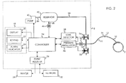
- Instrument 8 includes a user interface 18 that comprises a color graphic display panel 20, a keypad 22, and an alarm indicator 24.
- a user interface 18 that comprises a color graphic display panel 20, a keypad 22, and an alarm indicator 24.
- a similar user interface, employing a monochromatic graphic display panel has been described in US Pat No. 5,556,415 .
- Display panel 20 is employed for the selective display of any of the following information: the level of pressure within cuff 2 as measured by instrument 8 (cuff pressure); the pressure level to be maintained in cuff 2 when cuff 2 is pressurized (reference pressure level); alarm reference "limits" or values; alarm and warning messages describing detected alarm events; magnitudes of detected leaks and leakage trends; menus of commands for the operation of instrument 8; and other information and instructions pertinent to the operation of instrument 8.
- cuff pressure the level of pressure within cuff 2 as measured by instrument 8
- reference pressure level the pressure level to be maintained in cuff 2 when cuff 2 is pressurized
- alarm reference "limits" or values alarm and warning messages describing detected alarm events
- magnitudes of detected leaks and leakage trends menus of commands for the operation of instrument 8
- Keypad 22 provides a means for the user of instrument 8 to control the operation of instrument 8.
- Instrument 8 signals the presence of alarm conditions via alarm indicator 24 and symbols and text messages describing the alarm condition displayed upon display panel 20.
- Alarm indictor 24 includes a visual indicator in the form of a red lamp and a speaker for generating audio tones.
- An example of a detected alarm condition that requires the user's attention is the detection of a hazardous leak from cuff 2 or from the tubing and connectors forming the pneumatic passageway between cuff 2 and instrument 8.
- keypad 22 could be replaced by a touch screen interface to display panel 20 allowing the user to interact with instrument 8 by touching selected areas of display panel 20; a multi segment LCD or LED display could be selected for display panel 20; or the user interface could be provided by another device in communication with instrument 8.
- Instrument 8 maintains a register of events, similar to that described in US Pat. No. 5,911,735 , to record events and store the levels of relevant parameters at the time of the event such as cuff pressure, reference pressure level, estimated magnitude of leakage, inflation time, and alarm thresholds.
- Events that are recorded and stored by event register 26 shown in FIG. 2 include: hazardous leakage from cuff 2 and the connection between cuff 2 and instrument 8; the pressurization of cuff 2; the deflation of cuff 2; adjustments made to the reference pressure level; detected alarm conditions and adjustments made to alarm limits.
- Event printer 28 is connected to instrument 8 via interface cable 30.
- Event printer 28 provides a hard copy printout of the events and the levels of parameters associated with the event as recorded and stored by instrument 8.
- a record of events may be communicated by instrument 8 to an external operating room information network 32 for subsequent display along with data collected from other instrumentation in the operating room.
- event register 26 may in response to a request communicate the current levels of operating parameters including cuff pressure, cuff reference pressure, magnitude of leakage, inflation time, and other parameters relevant to the operation of instrument 8 to printer 28 and to network 32.
- controller 34 is a microcontroller typical of those known in the art with associated memory, analog, and digital peripheral interface circuitry, and other support components. Controller 34 executes software programs that control the operation of instrument 8 as described below. For clarity, and to enable a better understanding of the principles of the invention, some functions that are performed by controller 34 are described and shown in FIG. 2 as separate functional blocks. These function blocks are pressure regulator 36, leak detector 38 and event register 26.
- the assemblage of components for regulating cuff pressure include a source of pressurized gas that is generated by pneumatic pump 40 which is pneumatically connected to reservoir 42 by tubing 44.
- pump 40 operates to pressurize reservoir 42.
- Reservoir pressure transducer 46 is pneumatically connected by tubing 48 to reservoir 42 and generates a signal indicative of the pressure within reservoir 42, which is communicated to controller 34.
- Controller 34 activates pump 40 to maintain the pressure in reservoir 42 near a predetermined level. It will be appreciated that an external source of pressurized gas for the pressurization of cuff 2 could be provided to instrument 8 eliminating the necessity for pump 40 and reservoir 42.
- Pressure regulator component 36 receives a cuff pressure signal indicative of the pressure within cuff 2 from pressure transducer 50.
- Pressure transducer 50 is pneumatically connected to cuff 2 via manifold 52 and the pneumatic passageway formed by tubing 16, connectors 12 and 14, and cuff tubing 10.
- the cuff pressure signal is communicated to controller 34 and leak detector 38 by pressure regulator 36.
- cuff pressure transducer 50 shares a common pneumatic connection to cuff 2 with pressure increase valve 54 and pressure decrease valve 56.
- Other configurations of pneumatic connection to cuff 2 may be employed, for example, an additional port may be included in cuff 2 for direct connection to transducer 50, or transducer 50 may be incorporated into cuff 2.
- pressure regulator 36 When enabled by controller 34, pressure regulator 36 operates to maintain the pressure in cuff 2 (cuff pressure) near the reference pressure level by selectively actuating pressure increase valve 54 and pressure decrease valve 56.
- the reference pressure level may be adjusted and set by the user of instrument 8 via user interface 18 and also adjusted and set automatically by controller 34 in response to the physiologic condition of patient 2 as described in the prior art.
- Pressure increase valve 54 is an electrically operated normally closed pneumatic valve.
- the inlet of valve 54 is pneumatically connected via tubing 58 to reservoir 42, the outlet of valve 54 is connected to cuff 2 via the pneumatic passageway formed by manifold 52, tubing 16, connectors 14 and 12, and cuff tubing 10.
- a pressure increase signal from pressure regulator 36 supplies electrical power for the operation of pressure increase valve 54.
- When supplied with electrical energy valve 54 opens to allow gas to flow from reservoir 42 to cuff 2, thereby increasing the pressure of gas in the inflatable portion of cuff 2.
- the amount of electrical power supplied by pressure regulator 36 to valve 54 controls the average rate of gas flow through valve 54.
- the electrical characteristics of the pressure increase signal are adapted to be appropriate for the operating requirements of valve 54.
- Valve 54 may be configured as an electrically operated proportional valve wherein the rate of gas flow through valve 54 varies as a function of the electrical current supplied to the valve.
- valve 54 may be configured as an electrically operated solenoid valve that may be either fully open or fully closed; the average rate of gas flow through the valve may be controlled by pulse width modulating the electrical current supplied to the valve.
- the level of the pressure increase signal corresponds to a percentage of the maximum flow rate that valve 54 is capable of providing. At level of 0% valve 54 is closed and no gas flows through valve 54, at a level of 100% valve 54 is fully open and the flow rate through the valve is at a maximum.
- a pneumatic pump may be used in place of pressure increase valve 54 to directly supply gas to increase the pressure in cuff 2 in response to the pressure increase signal from pressure regulator 36.
- the rate at which gas is supplied by the pump to cuff 2 also corresponds to the level of the pressure increase signal, with 0% being no flow from the pump and 100% being the maximum flow rate that the pump is capable of.
- Pressure decrease valve 56 is also an electrically operated two position normally closed valve similar to valve 54.
- the inlet of valve 56 is pneumatically connected to cuff 2 via the pneumatic passageway formed by manifold 52, tubing 16, connectors 14 and 12, and cuff port 10, the outlet of valve 56 is open to atmosphere.
- a pressure decrease signal from pressure regulator 36 supplies electrical power for the operation of pressure decrease valve 56.
- Pressure regulator 36 sets the level of the pressure decrease signal to control the opening of valve 56.
- Pressure decrease valve 56 responds to the control signal from pressure regulator 36 to allow gas to be vented from cuff 2 to atmosphere, thereby decreasing the pressure of gas in cuff 2.
- a proportional integral control algorithm is used by pressure regulator 36 to calculate and set the levels of the pressure increase and pressure decrease control signals for valves 54 and 56 necessary to maintain the cuff pressure near the reference pressure level within a predetermined range. It will be appreciated by those skilled in the art that other pressure regulation control algorithms could be employed by pressure regulator 36 to set the levels of pressure increase and pressure decrease control signals for valves 54 and 56.
- Pressure regulator 36 will respond to a difference in pressure between the reference pressure level and the cuff pressure to add or remove gas from cuff 2 by adjusting the level of the control signals for valve 54 and valve 56 thereby increasing or decreasing the gas pressure within cuff 2 and maintaining the cuff pressure near the reference pressure level.
- the time taken by pressure regulator 36 to restore the cuff pressure to a level near the reference pressure level is typically less than 2 seconds.
- controller 34 will indicate a high or low pressure alarm condition to the user via user interface 18 and event register 26 will record a corresponding alarm event.
- an alarm will be indicated if the pressure regulator 36 cannot maintain the cuff pressure with a predetermined regulation limit of plus or minus 15 mmHg of the reference pressure level. It will be appreciated that other regulation limits may be selected and that they need not be symmetrical around the reference pressure level.
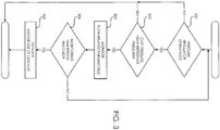
- the preferred embodiment includes leak detector 38 for estimating a magnitude of leakage.
- leak detector 38 monitors a parameter of operation of pressure regulator 36 that is indicative of the rate of gas flow into cuff 2 (304). The parameter is monitored for a period of time (306) after which an estimate of the magnitude of leakage is produced (308) by leak detector 38.
- Pressure regulator 36 will act to maintain the cuff pressure at a level near the reference pressure level by actuating pressure increase valve 54 to replenish the gas lost due to the leakage.
- the rate at which pressure regulator 36 must replenish gas lost due to leakage in order to maintain the cuff pressure near the reference pressure level is proportional to the magnitude of leakage from the system. As noted above, the rate at which gas flows through pressure increase valve 54 is a function of the level of the pressure increase signal.
- a parameter of operation of pressure regulator 36 that is indicative of the rate of gas flow into cuff 2 that is monitored by leakage detector 38 is the level of the pressure increase signal for valve 54.
- Other parameters of operation of pressure regulator 36 indicative of the rate of gas flow into cuff 2 may also be monitored by leak detector 38, such as the amount by which the reference pressure level exceeds the cuff pressure. Because pressure regulator 36 operates to maintain the cuff pressure near the reference level, the amount by which reference pressure exceeds the cuff pressure is an indication of the gas flow required to maintain the cuff pressure near the reference pressure level.
- leak detector 38 could be configured to monitor gas flow into cuff 2 directly by the addition of one or more gas flow meters to the pneumatic system; this however, would add significant cost and complexity to the system.
- Leak detector 38 estimates the magnitude of leakage by: monitoring the level of the pressure increase signal during a monitoring time period; and then estimating the magnitude of leakage as a function of the level of the pressure increase control signal throughout the monitoring time period.
- the magnitude of leakage estimated by leak detector 38 is proportional to the average flow rate through pressure increase valve 54 over the monitoring time period and is expressed a percentage of the maximum rate of flow of gas that instrument 8 is capable of providing to cuff 2 while maintaining the cuff pressure near the reference pressure level.
- the magnitude of leakage estimated by leakage detector 38 is indicated to the user via user interface 18.
- leak detector 38 monitors the level of the pressure increase signal over a monitoring time period that is substantially greater than the transient response time of pressure regulator.
- the monitoring time period is 20 seconds. It will be appreciated that other predetermined time periods could be selected and that a time period could be automatically selected by controller 34.
- leak detector 38 may be configured to monitor additional parameters of operation of pressure regulator 36 during the monitoring time period.
- leak detector 36 may be configured to also monitor the pressure decrease signal produced by pressure regulator 36 thereby improving the estimate of leakage magnitude by accounting for gas vented from the system due to regulator 36 responding to increases in cuff pressure caused by manipulation of the limb 4.
- Controller 34 compares the estimated magnitude of leakage produced by leakage detector 38 with predetermined thresholds in order to rank the magnitude of leakage and to indicate the degree of hazard to patient 6 from the possibility of arterial blood flowing past cuff 2.
- An estimated magnitude of leakage of 40% or more is indicated as a high hazard leak.
- a high hazard leak represents a high probability that pressure regulator 36 may not be able to continue to maintain the cuff pressure near the reference pressure level and that the pressure in cuff 2 may fall to a level that allows arterial blood to flow past cuff 2.
- a high hazard leak requires the immediate attention of the user to mitigate the leakage and is indicated by the activation of alarm indicator 24 and messages shown on display panel 20.
- Event register 26 also records the detection of a high hazard leak rate event for later printout by printer 28 and communication to network 32 for subsequent display.
- An estimated magnitude of leakage of 25% or more and less than 40% is indicated as a moderate hazard leak by controller 34.
- a moderate hazard leak represents a lesser probability that pressure regulator 36 will be unable to maintain the pressure in the cuff near the reference pressure.
- Moderate hazard leaks may not require the user's immediate attention but do require future action to repair or replace cuff 2 and the pneumatic connection between cuff 2 and instrument 8.
- a moderate hazard leak is indicated by warning messages shown on display panel 20.
- Event register 26 also records the detection of a moderate hazard leak event for later printout by printer 28 and communication to network 32 for subsequent display.
- a low hazard leak represents a leak with a low probability of potential hazard to the patient, and is however indicative of a potential problem with cuff 2 and the pneumatic connection between cuff 2 and instrument 8 that should be investigated further by the user.
- a low hazard leak is indicated by warning messages shown on display panel 20 at the end of the surgical procedure when cuff 2 is deflated.
- Event register 26 also records the detection of a low hazard leak event for later printout by printer 28 and communication to network 32 for subsequent display.
- controller 34 operates to detect trends in leakage magnitude. Controller 34 stores in memory the leakage magnitude estimated by leak detector 38 at predetermined time intervals of 1 minute. Each time controller 34 stores a leakage magnitude in memory it computes a leakage trend value from the difference between the recent leakage magnitude and the previously stored leakage magnitude. The leakage trend value is displayed via user interface 18. If leakage trend value exceeds a predetermined hazardous trend threshold limit, controller 34 alerts the user via user interface 18 that the magnitude of leakage is increasing. This may indicate that a high magnitude leak may soon develop and that mitigating action should be taken immediately.
- Event register 26 also records an event indicating that the magnitude of leakage has increased over time.
- the trend threshold limit is a predetermined increase in leakage magnitude of more than 10% during a 1-minute interval. It will be appreciated that other predetermined time intervals and threshold limits may be selected.
Landscapes
- Health & Medical Sciences (AREA)
- Life Sciences & Earth Sciences (AREA)
- Surgery (AREA)
- Engineering & Computer Science (AREA)
- Heart & Thoracic Surgery (AREA)
- Vascular Medicine (AREA)
- Nuclear Medicine, Radiotherapy & Molecular Imaging (AREA)
- Hematology (AREA)
- Biophysics (AREA)
- Biomedical Technology (AREA)
- Reproductive Health (AREA)
- Medical Informatics (AREA)
- Molecular Biology (AREA)
- Animal Behavior & Ethology (AREA)
- General Health & Medical Sciences (AREA)
- Public Health (AREA)
- Veterinary Medicine (AREA)
- Surgical Instruments (AREA)
- Measuring Pulse, Heart Rate, Blood Pressure Or Blood Flow (AREA)
Claims (7)
- Vorrichtung zur Beurteilung der Größenordnung der Leckage von Druckgas aus einem chirurgischen Tourniquet-System, umfassend:eine Druckregleranordnung (36);eine aufblasbare Tourniquet-Manschette (2) mit einem pneumatischen Schlauch zum Verbinden der Manschette (2) mit der Druckregleranordnung (36), wodurch ein Gasdurchgang zwischen der Manschette (2) und der Druckregleranordnung (36) hergestellt wird, worin die Druckregleranordnung (36) dafür konfiguriert ist, Druckgas zu und von der Manschette (2) und dem Durchgang, bei Betätigung durch ein elektrisches Signal, mit einer Durchflussrate zu führen, die als Funktion des elektrischen Stromniveaus des angelegten elektrischen Signals schwankt, um den Druck in der Manschette innerhalb eines Referenzdruckbereichs während eines Zeitraums aufrechtzuerhalten; undeinen Leckdetektor (38) zur Beurteilung einer Größenordnung der Leckage von Druckgas aus der Manschette (2) oder dem Durchgang, dadurch gekennzeichnet, dass der Leckdetektor (38) dafür konfiguriert ist, das Niveau des elektrischen Signals während des gesamten Zeitraums zu überwachen, und dadurch, dass die Beurteilung der Größenordnung der Leckage eine vorbestimmte Funktion des Niveaus des elektrischen Signals während des gesamten Zeitraums ist.
- Vorrichtung nach Anspruch 1, ferner umfassend ein vom Druckregler (36) gesteuertes Druckminderungsventil (56) zum Abführen von Gas an die Atmosphäre, worin der Leckdetektor (38) dafür konfiguriert ist, das vom Druckregler (36) erzeugte Druckminderungssignal zu überwachen, um einen vom Druckminderungsventil (56) bewusst aus der Manschette (2) abgeführten Gasfluss zu erfassen.
- Vorrichtung nach Anspruch 1, ferner umfassend ein Steuergerät, worin das Steuergerät (34) dafür konfiguriert ist, den Trend der Größenordnung der Leckage durch Vergleich zweier Beurteilungen der Größenordnung der Leckage zu bestimmen.
- Vorrichtung nach Anspruch 1, ferner umfassend ein Steuergerät, worin das Steuergerät (34) dafür konfiguriert ist, die beurteilte Größenordnung der Leckage einzustufen und einem Benutzer eine dieser Einstufung entsprechende Anzeige bereitzustellen.
- Vorrichtung nach Anspruch 1, worin der Leckdetektor (38) dafür konfiguriert ist, die Stromniveaus des elektrischen Signals für einen Überwachungszeitraum, der größer als etwa zwei Sekunden ist, zu überwachen.
- Vorrichtung nach Anspruch 1, worin der Zeitraum, während dem der Leckdetektor (38) die Größenordnung der Leckage beurteilt, erheblich größer ist als die von der Druckregleranordnung (36) benötigte Zeit zur Wiederherstellung des Druckniveaus in der Manschette (2) auf innerhalb des vorbestimmten Bereichs als Reaktion auf ein transientes, nicht der Leckage zuzuschreibendes Ereignis.
- Vorrichtung nach Anspruch 1, ferner umfassend ein Steuergerät, worin das Steuergerät (34) ferner einen Wert speichert, der für die Beurteilung der Größenordnung der Leckage indikativ ist, und worin die Vorrichtung ferner ein Kommunikationsmittel zur Übermittlung des gespeicherten Wertes an einen Ort fern von der Vorrichtung und zur Darbietung des gespeicherten Werts in einer für einen Benutzer wahrnehmbaren Form beinhaltet.
Applications Claiming Priority (2)
| Application Number | Priority Date | Filing Date | Title |
|---|---|---|---|
| US12/368,789 US8083763B2 (en) | 2009-02-10 | 2009-02-10 | Apparatus and method for estimating leakage in a surgical tourniquet system |
| PCT/CA2010/000176 WO2010091502A1 (en) | 2009-02-10 | 2010-02-08 | Apparatus and method for estimating leakage in a surgical tourniquet system |
Publications (3)
| Publication Number | Publication Date |
|---|---|
| EP2395928A1 EP2395928A1 (de) | 2011-12-21 |
| EP2395928A4 EP2395928A4 (de) | 2015-10-28 |
| EP2395928B1 true EP2395928B1 (de) | 2017-07-19 |
Family
ID=42541034
Family Applications (1)
| Application Number | Title | Priority Date | Filing Date |
|---|---|---|---|
| EP10740867.6A Active EP2395928B1 (de) | 2009-02-10 | 2010-02-08 | Vorrichtung zur leckagebeurteilung bei einem chirurgischen tourniquet-system |
Country Status (3)
| Country | Link |
|---|---|
| US (1) | US8083763B2 (de) |
| EP (1) | EP2395928B1 (de) |
| WO (1) | WO2010091502A1 (de) |
Families Citing this family (21)
| Publication number | Priority date | Publication date | Assignee | Title |
|---|---|---|---|---|
| US9113895B2 (en) * | 2009-02-19 | 2015-08-25 | Western Clinical Engineering Ltd. | Integrated tourniquet system |
| DE102013008035A1 (de) * | 2013-05-13 | 2014-11-13 | Sipos Aktorik Gmbh | Stellantrieb und Verfahren zum Betreiben eines Stellantriebs |
| USD737327S1 (en) | 2013-06-17 | 2015-08-25 | Covidien Lp | Display screen with a transitional leak detection icon |
| USD774057S1 (en) | 2013-06-17 | 2016-12-13 | Covidien Lp | Display screen with a graphical user interface for compliance monitoring |
| USD737328S1 (en) | 2013-06-17 | 2015-08-25 | Covidien Lp | Display screen with graphical user interface for venous refill detection |
| USD737855S1 (en) | 2013-06-17 | 2015-09-01 | Covidien Lp | Display screen with a transitional venous refill detection icon |
| USD760728S1 (en) | 2013-06-17 | 2016-07-05 | Covidien Lp | Display screen with graphical user interface for patient use meter reset |
| US9814467B2 (en) | 2014-07-10 | 2017-11-14 | Western Clinical Engineering Ltd. | Personalized tourniquet apparatus |
| US9039730B1 (en) | 2014-07-10 | 2015-05-26 | Western Clinical Engineering, Ltd. | Personalized tourniquet system having dual-purpose cuff |
| US9931126B2 (en) | 2014-07-10 | 2018-04-03 | Western Clinical Engineering Ltd. | Personalized tourniquet methods and apparatus |
| EP3171794B1 (de) | 2014-07-25 | 2024-03-13 | Western Clinical Engineering, Ltd. | Abbindungssystem zur personalisierten einschränkung des blutflusses |
| US9877733B1 (en) * | 2014-09-12 | 2018-01-30 | Mohammad R. Jafary | Anti-necrosis tourniquet device |
| US9618418B2 (en) * | 2014-11-14 | 2017-04-11 | Asm Technology Singapore Pte Ltd | System and method for detecting leakage in a gas pipeline |
| US10136903B2 (en) | 2016-03-28 | 2018-11-27 | Patrick James LYNCH | Tourniquet and method thereof having compliance logging and alert features, and a system thereof |
| US11672544B2 (en) * | 2017-08-04 | 2023-06-13 | Mayo Foundation For Medical Education And Research | Tourniquet training device |
| CN112040888B (zh) | 2018-03-05 | 2024-03-08 | 西方医疗工程有限公司 | 用于间歇性血管闭塞的个性化止血带 |
| CN109528263B (zh) * | 2018-11-26 | 2023-11-10 | 成都青山利康药业股份有限公司 | 一种智能化止血带 |
| WO2020163826A1 (en) * | 2019-02-07 | 2020-08-13 | Nathan Williams | Fast acting tourniquet device and methods for using same |
| US10973528B2 (en) * | 2019-05-29 | 2021-04-13 | The Government of the United States of America, as represented by the Secretary of Homeland Security | Modular system and apparatus for treating wounds |
| DE102020200892A1 (de) | 2020-01-27 | 2021-07-29 | Zf Friedrichshafen Ag | Pneumatisches Ausrücksystem für eine Kupplungsanordnung und eine Vorrichtung, ein Computerprogramm und ein Verfahren zum Bestimmen einer Leckagerate eines Fluids, insbesondere bei einem pneumatischen Ausrücksystem |
| CN119279805B (zh) * | 2024-12-12 | 2025-05-23 | 新光维医疗科技(苏州)股份有限公司 | 气腹机安全报警控制方法、系统、装置和存储介质 |
Family Cites Families (40)
| Publication number | Priority date | Publication date | Assignee | Title |
|---|---|---|---|---|
| US3239257A (en) | 1961-10-23 | 1966-03-08 | Charles S White | Elements having low friction pressure engagement and method of construction |
| US4321929A (en) | 1979-10-12 | 1982-03-30 | Lemelson Jerome H | Tourniquet |
| US4469099A (en) | 1980-10-02 | 1984-09-04 | Western Clinical Engineering Ltd. | Pneumatic torniquet |
| US4365635A (en) * | 1981-03-03 | 1982-12-28 | Bell & Howell Company | Pressure transducing methods and apparatus |
| US4479494A (en) | 1982-01-05 | 1984-10-30 | Western Clinical Engineering Ltd. | Adaptive pneumatic tourniquet |
| US4548198A (en) | 1983-04-15 | 1985-10-22 | Aspen Laboratories, Inc. | Automatic tourniquet |
| US4669485A (en) * | 1984-02-17 | 1987-06-02 | Cortronic Corporation | Apparatus and method for continuous non-invasive cardiovascular monitoring |
| US4605010A (en) | 1984-05-17 | 1986-08-12 | Western Clinical Engineering Ltd. | Pressurizing cuff |
| US4635635A (en) | 1984-11-29 | 1987-01-13 | Aspen Laboratories, Inc. | Tourniquet cuff |
| US4671290A (en) | 1985-01-15 | 1987-06-09 | Richards Medical Company | Automatic tourniquet |
| US4869265A (en) | 1987-04-03 | 1989-09-26 | Western Clinical Engineering Ltd. | Biomedical pressure transducer |
| US5181522A (en) | 1987-04-03 | 1993-01-26 | Abatis Medical Technologies Limited | Tourniquet for sensing and regulation of applied pressure |
| US5048536A (en) | 1987-04-03 | 1991-09-17 | Mcewen James A | Tourniquet for regulating applied pressures |
| US5254087A (en) | 1990-01-29 | 1993-10-19 | Ivra Systems, Inc. | Tourniquet apparatus for intravenous regional anesthesia |
| US5584853A (en) | 1990-01-29 | 1996-12-17 | Mcewen; James A. | Tourniquet cuff apparatus |
| US5556415A (en) | 1990-01-29 | 1996-09-17 | Mcewen; James A. | Physiologic tourniquet for intravenous regional anesthesia |
| US5607447A (en) * | 1993-09-28 | 1997-03-04 | Mcewen; James A. | Physiologic tourniquet |
| US5649954A (en) | 1991-09-30 | 1997-07-22 | Mcewen; James A. | Tourniquet cuff system |
| US5312431A (en) | 1991-09-30 | 1994-05-17 | Abatis Medical Technologies Limited | Occlusive cuff |
| US5741295A (en) | 1991-09-30 | 1998-04-21 | James A. McEwen | Overlapping tourniquet cuff system |
| DE4317600C2 (de) | 1993-05-27 | 1995-07-13 | Ulrich Heinrich C | Kompressionsapparat zur Herstellung einer künstlichen Blutleere an Extremitäten |
| US5575762A (en) | 1994-04-05 | 1996-11-19 | Beiersdorf-Jobst, Inc. | Gradient sequential compression system and method for reducing the occurrence of deep vein thrombosis |
| US5855589A (en) | 1995-08-25 | 1999-01-05 | Mcewen; James A. | Physiologic tourniquet for intravenous regional anesthesia |
| US5681339A (en) | 1996-08-12 | 1997-10-28 | Mcewen; James A. | Apparatus and method for monitoring the patency of tubing in a pneumatic medical device |
| US6213939B1 (en) | 1998-12-10 | 2001-04-10 | Mcewen James Allen | Hazard monitor for surgical tourniquet systems |
| US6589268B1 (en) | 1998-12-10 | 2003-07-08 | Mcewen James A. | Hazard monitor for surgical tourniquet systems |
| US6051016A (en) * | 1999-03-29 | 2000-04-18 | Instrumed, Inc. | System and method of controlling pressure in a surgical tourniquet |
| US7485131B2 (en) | 1999-03-29 | 2009-02-03 | Stryker Corporation | System and method for controlling pressure in a surgical tourniquet |
| US7166123B2 (en) | 1999-03-29 | 2007-01-23 | Instrumed | System and method for controlling pressure in a surgical tourniquet using a remote unit |
| US6371937B1 (en) * | 2000-03-27 | 2002-04-16 | I-Flow Corporation | Manometer infusion apparatus |
| GB0014789D0 (en) | 2000-06-17 | 2000-08-09 | Novamedix Distribution Limited | Medical appliance |
| US7076993B2 (en) | 2000-06-17 | 2006-07-18 | Novamedix Distribution Limited | Leakage detection method for a pressurised medical appliance |
| US6682547B2 (en) | 2001-08-14 | 2004-01-27 | Mcewen James Allen | Tourniquet cuff with identification apparatus |
| US7331977B2 (en) | 2001-08-14 | 2008-02-19 | Mcewen James A | Adaptive tourniquet cuff system |
| US7771453B2 (en) | 2005-03-31 | 2010-08-10 | Mcewen James A | Occlusion detector for dual-port surgical tourniquet systems |
| US7479154B2 (en) | 2005-05-05 | 2009-01-20 | Mcewen James A | Surgical tourniquet apparatus for measuring limb occlusion pressure |
| US20060287672A1 (en) | 2005-06-15 | 2006-12-21 | Western Clinical Engineering Ltd. | Tourniquet cuff with improved pneumatic passageway |
| US7955352B2 (en) | 2005-08-05 | 2011-06-07 | Western Clinical Engineering, Ltd | Surgical tourniquet cuff for limiting usage to improve safety |
| US8048105B2 (en) | 2007-04-19 | 2011-11-01 | Western Clinical Engineering Ltd. | Adaptive surgical tourniquet apparatus and method |
| US9113895B2 (en) | 2009-02-19 | 2015-08-25 | Western Clinical Engineering Ltd. | Integrated tourniquet system |
-
2009
- 2009-02-10 US US12/368,789 patent/US8083763B2/en active Active
-
2010
- 2010-02-08 WO PCT/CA2010/000176 patent/WO2010091502A1/en not_active Ceased
- 2010-02-08 EP EP10740867.6A patent/EP2395928B1/de active Active
Non-Patent Citations (1)
| Title |
|---|
| None * |
Also Published As
| Publication number | Publication date |
|---|---|
| WO2010091502A1 (en) | 2010-08-19 |
| EP2395928A1 (de) | 2011-12-21 |
| US8083763B2 (en) | 2011-12-27 |
| US20100204726A1 (en) | 2010-08-12 |
| EP2395928A4 (de) | 2015-10-28 |
Similar Documents
| Publication | Publication Date | Title |
|---|---|---|
| EP2395928B1 (de) | Vorrichtung zur leckagebeurteilung bei einem chirurgischen tourniquet-system | |
| US9113895B2 (en) | Integrated tourniquet system | |
| US8048105B2 (en) | Adaptive surgical tourniquet apparatus and method | |
| JP5011276B2 (ja) | デュアルポート式タニケットシステムの閉塞検知装置 | |
| EP1909657B1 (de) | Chirurgische staumanschette zur einschränkung der verwendung zur erhöhung der sicherheit | |
| US6213939B1 (en) | Hazard monitor for surgical tourniquet systems | |
| EP3166509B1 (de) | Personalisiertes abbindesystem | |
| US12023437B2 (en) | Insufflation system and insufflation control method | |
| EP1919373B1 (de) | Chirurgisches staumanschettensystem |
Legal Events
| Date | Code | Title | Description |
|---|---|---|---|
| PUAI | Public reference made under article 153(3) epc to a published international application that has entered the european phase |
Free format text: ORIGINAL CODE: 0009012 |
|
| 17P | Request for examination filed |
Effective date: 20110908 |
|
| AK | Designated contracting states |
Kind code of ref document: A1 Designated state(s): AT BE BG CH CY CZ DE DK EE ES FI FR GB GR HR HU IE IS IT LI LT LU LV MC MK MT NL NO PL PT RO SE SI SK SM TR |
|
| DAX | Request for extension of the european patent (deleted) | ||
| RA4 | Supplementary search report drawn up and despatched (corrected) |
Effective date: 20150925 |
|
| RIC1 | Information provided on ipc code assigned before grant |
Ipc: A61B 17/00 20060101ALN20150921BHEP Ipc: A61B 17/135 20060101AFI20150921BHEP Ipc: A61B 19/00 20060101ALN20150921BHEP |
|
| 17Q | First examination report despatched |
Effective date: 20160601 |
|
| REG | Reference to a national code |
Ref country code: DE Ref legal event code: R079 Ref document number: 602010043728 Country of ref document: DE Free format text: PREVIOUS MAIN CLASS: A61B0017132000 Ipc: A61B0017135000 |
|
| GRAP | Despatch of communication of intention to grant a patent |
Free format text: ORIGINAL CODE: EPIDOSNIGR1 |
|
| RIC1 | Information provided on ipc code assigned before grant |
Ipc: A61B 90/00 20160101ALN20170320BHEP Ipc: A61B 17/00 20060101ALN20170320BHEP Ipc: A61B 17/135 20060101AFI20170320BHEP |
|
| INTG | Intention to grant announced |
Effective date: 20170411 |
|
| GRAS | Grant fee paid |
Free format text: ORIGINAL CODE: EPIDOSNIGR3 |
|
| GRAA | (expected) grant |
Free format text: ORIGINAL CODE: 0009210 |
|
| AK | Designated contracting states |
Kind code of ref document: B1 Designated state(s): AT BE BG CH CY CZ DE DK EE ES FI FR GB GR HR HU IE IS IT LI LT LU LV MC MK MT NL NO PL PT RO SE SI SK SM TR |
|
| REG | Reference to a national code |
Ref country code: GB Ref legal event code: FG4D |
|
| REG | Reference to a national code |
Ref country code: CH Ref legal event code: EP |
|
| REG | Reference to a national code |
Ref country code: IE Ref legal event code: FG4D |
|
| REG | Reference to a national code |
Ref country code: AT Ref legal event code: REF Ref document number: 909584 Country of ref document: AT Kind code of ref document: T Effective date: 20170815 |
|
| REG | Reference to a national code |
Ref country code: DE Ref legal event code: R096 Ref document number: 602010043728 Country of ref document: DE |
|
| REG | Reference to a national code |
Ref country code: NL Ref legal event code: MP Effective date: 20170719 |
|
| REG | Reference to a national code |
Ref country code: LT Ref legal event code: MG4D |
|
| REG | Reference to a national code |
Ref country code: AT Ref legal event code: MK05 Ref document number: 909584 Country of ref document: AT Kind code of ref document: T Effective date: 20170719 |
|
| REG | Reference to a national code |
Ref country code: FR Ref legal event code: PLFP Year of fee payment: 9 |
|
| PG25 | Lapsed in a contracting state [announced via postgrant information from national office to epo] |
Ref country code: NL Free format text: LAPSE BECAUSE OF FAILURE TO SUBMIT A TRANSLATION OF THE DESCRIPTION OR TO PAY THE FEE WITHIN THE PRESCRIBED TIME-LIMIT Effective date: 20170719 Ref country code: SE Free format text: LAPSE BECAUSE OF FAILURE TO SUBMIT A TRANSLATION OF THE DESCRIPTION OR TO PAY THE FEE WITHIN THE PRESCRIBED TIME-LIMIT Effective date: 20170719 Ref country code: HR Free format text: LAPSE BECAUSE OF FAILURE TO SUBMIT A TRANSLATION OF THE DESCRIPTION OR TO PAY THE FEE WITHIN THE PRESCRIBED TIME-LIMIT Effective date: 20170719 Ref country code: FI Free format text: LAPSE BECAUSE OF FAILURE TO SUBMIT A TRANSLATION OF THE DESCRIPTION OR TO PAY THE FEE WITHIN THE PRESCRIBED TIME-LIMIT Effective date: 20170719 Ref country code: AT Free format text: LAPSE BECAUSE OF FAILURE TO SUBMIT A TRANSLATION OF THE DESCRIPTION OR TO PAY THE FEE WITHIN THE PRESCRIBED TIME-LIMIT Effective date: 20170719 Ref country code: NO Free format text: LAPSE BECAUSE OF FAILURE TO SUBMIT A TRANSLATION OF THE DESCRIPTION OR TO PAY THE FEE WITHIN THE PRESCRIBED TIME-LIMIT Effective date: 20171019 Ref country code: LT Free format text: LAPSE BECAUSE OF FAILURE TO SUBMIT A TRANSLATION OF THE DESCRIPTION OR TO PAY THE FEE WITHIN THE PRESCRIBED TIME-LIMIT Effective date: 20170719 |
|
| PG25 | Lapsed in a contracting state [announced via postgrant information from national office to epo] |
Ref country code: ES Free format text: LAPSE BECAUSE OF FAILURE TO SUBMIT A TRANSLATION OF THE DESCRIPTION OR TO PAY THE FEE WITHIN THE PRESCRIBED TIME-LIMIT Effective date: 20170719 Ref country code: PL Free format text: LAPSE BECAUSE OF FAILURE TO SUBMIT A TRANSLATION OF THE DESCRIPTION OR TO PAY THE FEE WITHIN THE PRESCRIBED TIME-LIMIT Effective date: 20170719 Ref country code: BG Free format text: LAPSE BECAUSE OF FAILURE TO SUBMIT A TRANSLATION OF THE DESCRIPTION OR TO PAY THE FEE WITHIN THE PRESCRIBED TIME-LIMIT Effective date: 20171019 Ref country code: LV Free format text: LAPSE BECAUSE OF FAILURE TO SUBMIT A TRANSLATION OF THE DESCRIPTION OR TO PAY THE FEE WITHIN THE PRESCRIBED TIME-LIMIT Effective date: 20170719 Ref country code: GR Free format text: LAPSE BECAUSE OF FAILURE TO SUBMIT A TRANSLATION OF THE DESCRIPTION OR TO PAY THE FEE WITHIN THE PRESCRIBED TIME-LIMIT Effective date: 20171020 Ref country code: IS Free format text: LAPSE BECAUSE OF FAILURE TO SUBMIT A TRANSLATION OF THE DESCRIPTION OR TO PAY THE FEE WITHIN THE PRESCRIBED TIME-LIMIT Effective date: 20171119 |
|
| REG | Reference to a national code |
Ref country code: DE Ref legal event code: R097 Ref document number: 602010043728 Country of ref document: DE |
|
| PG25 | Lapsed in a contracting state [announced via postgrant information from national office to epo] |
Ref country code: DK Free format text: LAPSE BECAUSE OF FAILURE TO SUBMIT A TRANSLATION OF THE DESCRIPTION OR TO PAY THE FEE WITHIN THE PRESCRIBED TIME-LIMIT Effective date: 20170719 Ref country code: CZ Free format text: LAPSE BECAUSE OF FAILURE TO SUBMIT A TRANSLATION OF THE DESCRIPTION OR TO PAY THE FEE WITHIN THE PRESCRIBED TIME-LIMIT Effective date: 20170719 Ref country code: RO Free format text: LAPSE BECAUSE OF FAILURE TO SUBMIT A TRANSLATION OF THE DESCRIPTION OR TO PAY THE FEE WITHIN THE PRESCRIBED TIME-LIMIT Effective date: 20170719 |
|
| PLBE | No opposition filed within time limit |
Free format text: ORIGINAL CODE: 0009261 |
|
| STAA | Information on the status of an ep patent application or granted ep patent |
Free format text: STATUS: NO OPPOSITION FILED WITHIN TIME LIMIT |
|
| PG25 | Lapsed in a contracting state [announced via postgrant information from national office to epo] |
Ref country code: EE Free format text: LAPSE BECAUSE OF FAILURE TO SUBMIT A TRANSLATION OF THE DESCRIPTION OR TO PAY THE FEE WITHIN THE PRESCRIBED TIME-LIMIT Effective date: 20170719 Ref country code: SK Free format text: LAPSE BECAUSE OF FAILURE TO SUBMIT A TRANSLATION OF THE DESCRIPTION OR TO PAY THE FEE WITHIN THE PRESCRIBED TIME-LIMIT Effective date: 20170719 Ref country code: IT Free format text: LAPSE BECAUSE OF FAILURE TO SUBMIT A TRANSLATION OF THE DESCRIPTION OR TO PAY THE FEE WITHIN THE PRESCRIBED TIME-LIMIT Effective date: 20170719 Ref country code: SM Free format text: LAPSE BECAUSE OF FAILURE TO SUBMIT A TRANSLATION OF THE DESCRIPTION OR TO PAY THE FEE WITHIN THE PRESCRIBED TIME-LIMIT Effective date: 20170719 |
|
| 26N | No opposition filed |
Effective date: 20180420 |
|
| PG25 | Lapsed in a contracting state [announced via postgrant information from national office to epo] |
Ref country code: SI Free format text: LAPSE BECAUSE OF FAILURE TO SUBMIT A TRANSLATION OF THE DESCRIPTION OR TO PAY THE FEE WITHIN THE PRESCRIBED TIME-LIMIT Effective date: 20170719 |
|
| REG | Reference to a national code |
Ref country code: CH Ref legal event code: PL |
|
| PG25 | Lapsed in a contracting state [announced via postgrant information from national office to epo] |
Ref country code: MC Free format text: LAPSE BECAUSE OF FAILURE TO SUBMIT A TRANSLATION OF THE DESCRIPTION OR TO PAY THE FEE WITHIN THE PRESCRIBED TIME-LIMIT Effective date: 20170719 |
|
| REG | Reference to a national code |
Ref country code: IE Ref legal event code: MM4A |
|
| REG | Reference to a national code |
Ref country code: BE Ref legal event code: MM Effective date: 20180228 |
|
| PG25 | Lapsed in a contracting state [announced via postgrant information from national office to epo] |
Ref country code: LU Free format text: LAPSE BECAUSE OF NON-PAYMENT OF DUE FEES Effective date: 20180208 Ref country code: LI Free format text: LAPSE BECAUSE OF NON-PAYMENT OF DUE FEES Effective date: 20180228 Ref country code: CH Free format text: LAPSE BECAUSE OF NON-PAYMENT OF DUE FEES Effective date: 20180228 |
|
| PG25 | Lapsed in a contracting state [announced via postgrant information from national office to epo] |
Ref country code: IE Free format text: LAPSE BECAUSE OF NON-PAYMENT OF DUE FEES Effective date: 20180208 |
|
| PG25 | Lapsed in a contracting state [announced via postgrant information from national office to epo] |
Ref country code: BE Free format text: LAPSE BECAUSE OF NON-PAYMENT OF DUE FEES Effective date: 20180228 |
|
| PG25 | Lapsed in a contracting state [announced via postgrant information from national office to epo] |
Ref country code: MT Free format text: LAPSE BECAUSE OF NON-PAYMENT OF DUE FEES Effective date: 20180208 |
|
| PG25 | Lapsed in a contracting state [announced via postgrant information from national office to epo] |
Ref country code: TR Free format text: LAPSE BECAUSE OF FAILURE TO SUBMIT A TRANSLATION OF THE DESCRIPTION OR TO PAY THE FEE WITHIN THE PRESCRIBED TIME-LIMIT Effective date: 20170719 |
|
| PG25 | Lapsed in a contracting state [announced via postgrant information from national office to epo] |
Ref country code: HU Free format text: LAPSE BECAUSE OF FAILURE TO SUBMIT A TRANSLATION OF THE DESCRIPTION OR TO PAY THE FEE WITHIN THE PRESCRIBED TIME-LIMIT; INVALID AB INITIO Effective date: 20100208 Ref country code: PT Free format text: LAPSE BECAUSE OF FAILURE TO SUBMIT A TRANSLATION OF THE DESCRIPTION OR TO PAY THE FEE WITHIN THE PRESCRIBED TIME-LIMIT Effective date: 20170719 |
|
| PG25 | Lapsed in a contracting state [announced via postgrant information from national office to epo] |
Ref country code: CY Free format text: LAPSE BECAUSE OF FAILURE TO SUBMIT A TRANSLATION OF THE DESCRIPTION OR TO PAY THE FEE WITHIN THE PRESCRIBED TIME-LIMIT Effective date: 20170719 Ref country code: MK Free format text: LAPSE BECAUSE OF NON-PAYMENT OF DUE FEES Effective date: 20170719 |
|
| P01 | Opt-out of the competence of the unified patent court (upc) registered |
Effective date: 20230506 |
|
| PGFP | Annual fee paid to national office [announced via postgrant information from national office to epo] |
Ref country code: GB Payment date: 20241219 Year of fee payment: 16 |
|
| PGFP | Annual fee paid to national office [announced via postgrant information from national office to epo] |
Ref country code: FR Payment date: 20241209 Year of fee payment: 16 |
|
| PGFP | Annual fee paid to national office [announced via postgrant information from national office to epo] |
Ref country code: DE Payment date: 20241217 Year of fee payment: 16 |