EP2595237A1 - Chuck mechanism of charge-discharge test device for thin secondary battery - Google Patents
Chuck mechanism of charge-discharge test device for thin secondary battery Download PDFInfo
- Publication number
- EP2595237A1 EP2595237A1 EP11806432.8A EP11806432A EP2595237A1 EP 2595237 A1 EP2595237 A1 EP 2595237A1 EP 11806432 A EP11806432 A EP 11806432A EP 2595237 A1 EP2595237 A1 EP 2595237A1
- Authority
- EP
- European Patent Office
- Prior art keywords
- chuck
- holding member
- secondary battery
- thin secondary
- members
- Prior art date
- Legal status (The legal status is an assumption and is not a legal conclusion. Google has not performed a legal analysis and makes no representation as to the accuracy of the status listed.)
- Granted
Links
Images







Classifications
-
- H—ELECTRICITY
- H01—ELECTRIC ELEMENTS
- H01M—PROCESSES OR MEANS, e.g. BATTERIES, FOR THE DIRECT CONVERSION OF CHEMICAL ENERGY INTO ELECTRICAL ENERGY
- H01M10/00—Secondary cells; Manufacture thereof
- H01M10/42—Methods or arrangements for servicing or maintenance of secondary cells or secondary half-cells
- H01M10/48—Accumulators combined with arrangements for measuring, testing or indicating the condition of cells, e.g. the level or density of the electrolyte
- H01M10/482—Accumulators combined with arrangements for measuring, testing or indicating the condition of cells, e.g. the level or density of the electrolyte for several batteries or cells simultaneously or sequentially
-
- H—ELECTRICITY
- H01—ELECTRIC ELEMENTS
- H01M—PROCESSES OR MEANS, e.g. BATTERIES, FOR THE DIRECT CONVERSION OF CHEMICAL ENERGY INTO ELECTRICAL ENERGY
- H01M10/00—Secondary cells; Manufacture thereof
- H01M10/42—Methods or arrangements for servicing or maintenance of secondary cells or secondary half-cells
- H01M10/4285—Testing apparatus
-
- H—ELECTRICITY
- H02—GENERATION; CONVERSION OR DISTRIBUTION OF ELECTRIC POWER
- H02J—ELECTRIC POWER NETWORKS; CIRCUIT ARRANGEMENTS OR SYSTEMS FOR SUPPLYING OR DISTRIBUTING ELECTRIC POWER; SYSTEMS FOR STORING ELECTRIC ENERGY
- H02J7/00—Circuit arrangements for charging or discharging batteries or for supplying loads from batteries
- H02J7/70—Circuit arrangements for charging or discharging batteries or for supplying loads from batteries characterised by the mechanical construction
-
- Y—GENERAL TAGGING OF NEW TECHNOLOGICAL DEVELOPMENTS; GENERAL TAGGING OF CROSS-SECTIONAL TECHNOLOGIES SPANNING OVER SEVERAL SECTIONS OF THE IPC; TECHNICAL SUBJECTS COVERED BY FORMER USPC CROSS-REFERENCE ART COLLECTIONS [XRACs] AND DIGESTS
- Y02—TECHNOLOGIES OR APPLICATIONS FOR MITIGATION OR ADAPTATION AGAINST CLIMATE CHANGE
- Y02E—REDUCTION OF GREENHOUSE GAS [GHG] EMISSIONS, RELATED TO ENERGY GENERATION, TRANSMISSION OR DISTRIBUTION
- Y02E60/00—Enabling technologies; Technologies with a potential or indirect contribution to GHG emissions mitigation
- Y02E60/10—Energy storage using batteries
-
- Y—GENERAL TAGGING OF NEW TECHNOLOGICAL DEVELOPMENTS; GENERAL TAGGING OF CROSS-SECTIONAL TECHNOLOGIES SPANNING OVER SEVERAL SECTIONS OF THE IPC; TECHNICAL SUBJECTS COVERED BY FORMER USPC CROSS-REFERENCE ART COLLECTIONS [XRACs] AND DIGESTS
- Y02—TECHNOLOGIES OR APPLICATIONS FOR MITIGATION OR ADAPTATION AGAINST CLIMATE CHANGE
- Y02P—CLIMATE CHANGE MITIGATION TECHNOLOGIES IN THE PRODUCTION OR PROCESSING OF GOODS
- Y02P70/00—Climate change mitigation technologies in the production process for final industrial or consumer products
- Y02P70/50—Manufacturing or production processes characterised by the final manufactured product
Definitions
- the present invention relates to a mechanism for chucking electrode terminals, used in a charge-discharge test device for a plate-shaped thin secondary battery.
- a thin secondary battery 1 having a plate shape as in Figs. 13 and 14 is used in many technical fields.
- the thin secondary battery 1 has a configuration in which a pair of sheet-shaped electrode terminals 5, 7 project out of a flat case 3 in one direction.
- Patent Document 1 discloses a charge-discharge and inspection system for thin secondary batteries of this type.
- the conventional example includes: a battery container in which multiple thin secondary batteries are housed and arranged in a certain direction by inserting electrode terminals of thin secondary batteries into multiple insertion holes formed in a bottom plate of the battery container; a chuck mechanism for chucking the electrode terminals projecting from the insertion holes of the battery container; a first action (elevating) mechanism for moving the chuck mechanism; and a second action (elevating) mechanism for driving the chuck mechanism.
- the conventional example is configured such that after placing and arranging the multiple thin secondary batteries in the battery container, the chuck mechanism is moved closer to the battery container by the first action mechanism and is then driven to chuck the electrode terminals by the second action mechanism.
- the conventional example includes individual mechanisms for the first action (elevating) of moving the chuck mechanism closer to the battery container, and the second action (elevating) of chucking the electrode terminals by the chuck mechanism. Accordingly, the actions need to be controlled independently, which may complicate the action controllability.
- the present invention has been made in view of the above circumstances, and aims to provide a chuck mechanism of a charge-discharge test device for a thin secondary battery, the mechanism having excellent action controllability.
- a chuck mechanism of a charge-discharge test device for a thin secondary battery includes a chuck unit including: a chuck drive part which is movable in a direction toward a battery container body housing a thin secondary battery; and a chuck activation part which is located away from the chuck drive part in the direction toward the battery container body and whose movement in the same direction is restricted.
- the chuck drive part when the chuck unit is moved in the direction toward the battery container body, the chuck drive part activates a chuck member of the chuck activation part whose movement in the same direction is restricted.
- the chuck drive part is a roller holding member formed to be movable in a front-rear direction of a supporting base by driving of drive means attached to the supporting base, and including on a front surface thereof multiple pairs of rollers rotatably disposed in parallel in a left-right direction of the supporting base;
- the chuck activation part is a chuck holding member attached in front of the roller holding member via a spring member, and including multiple chuck members each formed of a pair of strip-shaped metal plates which are inserted between the corresponding pair of rollers and whose tip end sides are spread open toward the front in a substantially V-shape in plan view;
- the supporting base includes a restriction part for restricting a forward movement of the chuck holding member; and the movement of the chuck holding member moved forward together with the roller holding member by the driving of the drive means is restricted by the restriction part, as well as the tip end sides
- the roller holding member is formed by disposing multiple divided roller holding members in parallel on two upper and lower shafts arranged in the left-right direction of the supporting base;
- the chuck holding member is formed by disposing multiple divided chuck holding members in parallel on two upper and lower shafts arranged in the left-right direction of the supporting base;
- the spring member extends between each of coupling brackets attached to left and right outer peripheries of the roller holding member and a corresponding one of coupling brackets attached to left and right outer peripheries of the chuck holding member.
- an oxide film peeling and nipping member is attached to tip ends of the pair of metal plates.
- a slit is formed in the tip ends of the pair of metal plates in a front-rear direction, and the oxide film peeling and nipping member is attached to each of tip ends of each metal plate partitioned by the slit.
- the operation of moving the chuck unit in the direction toward the battery container enables the chuck drive part to activate the chuck member of the chuck activation part to chuck a thin secondary battery.
- the present invention has an advantage of excellent action controllability.
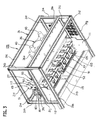
- Figs. 1 to 12 show an embodiment of a chuck mechanism according to claims 1 to 5.
- reference sign 31 denotes a supporting base having a rectangular solid shape formed of 15 columns 31 a to 31o arranged in the front, back, left, and right of the supporting base 31.
- a supporting plate 33 covering an area between the center of the supporting base 31 in a front-rear direction and a back portion side thereof is fixed on three columns 31i to 31k laid laterally across substantial centers of the left and right sides and a substantial center of the back side of the support base 31.
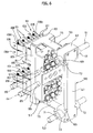
- a double-acting air cylinder (drive means) 36 including a piston rod 35 extending and contracting in the front-rear direction of the supporting base 31 is mounted in the center of the supporting plate 33.
- a roller holding member (chuck drive part) 37 including multiple pairs of rollers 89 for activating chuck members 101 of a later-mentioned chuck holding member (chuck activation part) 41 is attached to a tip end of the piston rod 35, and the chuck holding member 41 is attached in front of the roller holding member 37 with two each of left and right coil springs 39 interposed between the chuck holding member 41 and the roller holding member 37.
- columnar guide members 43 are inserted in a casing 36a of the air cylinder 36 on the respective left and right sides of the piston rod 35 along the piston rod 35, and a thick plate-shaped coupling member 45 is fixed on tip ends of both guide members 43 and of the piston rod 35.
- a long supporting bracket 47 substantially U-shaped in plan view for supporting the roller holding member 37 is attached to the coupling member 45 in such a manner as to extend in the left-right direction of the supporting base 31.
- Left and right flanges 49 of the supporting bracket 47 are bent in an L-shape toward the front of the supporting base 31.
- roller holding member 37 is formed by disposing multiple divided roller holding members 55 laterally in parallel on two upper and lower shafts 51, 53 installed across the left and right flanges 49.
- Figs. 5 and 6 each show one of the divided roller holding members 55 and a divided chuck holding member 57.
- the roller holding member 37 is formed by disposing the multiple divided roller holding members 55 in parallel on the shafts 51, 53, and as will be mentioned later, the chuck holding member 41 is formed by disposing multiple divided chuck holding members 57 in parallel on two upper and lower shafts 59, 61.
- two upper and lower block members 63, 65 having a rectangular solid shape are coupled by a single coupling plate 67.
- a shaft insertion hole 69 into which the shaft 51 is inserted is formed in the center of the upper block member 63, and a shaft insertion hole 71 into which the shaft 53 is inserted is provided in the center of the lower block member 65.
- Tubular spacers 73 through which the shaft insertion holes 69, 71 are open project on left and right sides of each of the block members 63, 65.
- a pair of upper and lower arm members 75 substantially L-shaped in cross section are respectively screwed on the front sides of the block members 63, 65.
- a roller attachment plate 81 in which upper and lower rectangular openings 77, 79 are formed is integrally formed on tip ends of the arm members 75, and the roller attachment plate 81 is disposed to face the coupling plate 67.
- a pair of roller attachment brackets 83, 85 are fixed in upper and lower parts of each of the openings 77, 79 of the roller attachment plate 81, and an even number of roller attachment holes 87 are provided at equal intervals on tip end sides of each of the roller attachment brackets 83, 85 in such a manner that the sets of roller attachment holes 87 face each other.
- the multiple pairs of rollers 89 (four pairs on each of the upper and lower pairs of brackets in the embodiment) are rotatably attached to the roller attachment holes 87 between the upper and lower pairs of roller attachment brackets 83, 85.
- the divided roller holding member 55 is thus configured, and as mentioned earlier, the two upper and lower shafts 51, 53 installed across the left and right flanges 49 of the supporting bracket 47 are inserted into the upper and lower shaft insertion holes 71 of each of the divided roller holding members 55 (block member 63, 65). As in Figs. 2 and 3 , the two shafts 51, 53 are inserted into holding members 91 extending frontward from the centers of upper and lower parts of the supporting bracket 47, respectively. On left and right sides of the holding members 91, four each of the divided roller holding members 55 are disposed in parallel between the shafts 51, 53 with the spacers 73 interposed therebetween. The roller holding member 37 is supported by the supporting bracket 47. Additionally, a coupling bracket 93 L-shaped in cross section is attached to an outer periphery of each of the left and right flanges 49.
- the chuck holding member 41 also has a configuration in which the multiple divided chuck holding members 57 are disposed laterally in parallel on the two upper and lower shafts 59, 61 arranged in the left-right direction of the supporting base 31.
- the divided chuck holding member 57 is paired with the divided roller holding member 55 to form a unit, and thus the roller holding member 37 and the chuck holding member 41 form a chuck unit as a whole.
- reference sign 95 denotes a thick plate-shaped chuck attachment member disposed along the roller attachment plate 81 between the arm members 75, and the shafts 59, 61 are inserted into shaft insertion holes 97, 99, which are provided in upper and lower parts of the center of the chuck attachment member, in such a manner as to extend in the left-right direction of the supporting base 31. Then, the multiple (four each in upper and lower parts of the chuck attachment member 95 in the embodiment) chuck members 101 are disposed laterally in parallel in upper and lower rows in correspondence with the aforementioned pairs of rollers 89, in upper and lower parts of a front surface of the chuck attachment member 95.
- the chuck member 101 is formed of a pair of strip-shaped metal plates 103, 105 made of phosphor bronze, for example, having a spring-like nature.
- the back end sides of the metal plates 103, 105 are lapped and joined together and penetrate a through hole (not shown) formed in the chuck attachment member 95.
- the back end of one metal plate 103 projecting from a back surface of the chuck attachment member 95 is bent in an L-shape along the back surface of the chuck attachment member 95, and screwed onto the back surface.
- the back end of the other metal plate 105 projecting from the back surface of the chuck attachment member 95 is bent in an L-shape along the back surface of the chuck attachment member 95, and screwed onto the back surface.
- the back ends of the metal plates 103, 105 are cut into short lengths in upper and lower directions and disposed in upper and lower parts of the back surface of the chuck attachment member 95.
- wires of a charge-discharge test device can be connected to the back ends of the metal plates 103, 105 projecting from the back surface of the chuck attachment member 95.
- each chuck member 101 the metal plates 103, 105 projecting toward the front of the chuck attachment member 95, and each pair of metal plates 103, 105 are inserted between the corresponding pair of rollers 89.
- the tip end sides of the metal plates 103, 105 inserted between the pair of rollers 89 spread open in a substantially V-shape in plan view, and the tip ends thereof are bent slightly inward.
- the roller holding member 37 is moved forward by driving of the air cylinder 36, the metal plates 103, 105 (the chuck member 101) being spread open in the substantially V-shape in plan view are closed by the pair of rollers 89.
- a slit 106 is formed in the front-rear direction at the tip end of each of the metal plates 103, 105.
- a pair of oxide film peeling and nipping members (hereinafter refered to as “peeling and nipping members”) 108 are fixed by riveting, on the tip end sides of the metal plates 103, 105 partitioned by the slit 106.
- an attachment hole 110 to which the peeling and nipping member 108 is fixed by riveting is provided on the tip end side of each of the metal plates 103, 105 partitioned by the slit 106.
- the peeling and nipping member 108 is formed of a leg member 108a fixed by riveting to the attachment hole 110, and a thick disk-shaped head portion 108b having a circular shape in plan view integrally formed with the leg member 108a.
- irregularities 108c are formed by knurling on a nipping surface which is a top part of the head portion 108b.
- the irregularities 108c of the pair of peeling and nipping members 108 are pressed against the front and back sides of the electrode terminals 5, 7 to peel off the oxide film formed on the surfaces of the electrode terminals 5, 7.
- the chuck member 101 is configured in the above-mentioned manner, and as has been described, the four chuck members 101 are disposed laterally in parallel at upper and lower parts of the front surface of the chuck attachment member 95. Additionally, the chuck holding member 41 is formed by disposing the divided chuck holding members 57 in parallel between the two shafts 59, 61 in correspondence with the divided roller holding members 55.
- a coupling bracket 107 L-shaped in cross section is attached to projecting ends of the shafts 59, 61 projecting outward from each of the left and right divided chuck holding members 57.
- the coupling brackets 107 and the coupling brackets 93 are held to be movable in the front-rear direction of the supporting base 31 by guide members 109 attached on left and right sides of the supporting base 31.
- One guide member 109 is supported by a plate 111 which is attached among the columns 31 g, 311, 31i on the right side of the supporting base 31, and the other guide member 109 is supported by a plate 113 which is attached among the columns 31h, 31j, 31m on the left side of the supporting base 31.
- the chuck member 101 is disposed inside the supporting base 31 as in Figs. 4 and 7 .
- a column 119 (restriction part) is installed to vertically bridge the columns 31a, 31b of the supporting base 31 at the centers thereof.
- the shafts 59, 61 also come into contact with the column 119 to restrict forward movement of the chuck holding member 41.
- reference signs 121, 123 denote connectors for connecting wires of a charge-discharge device to the back ends of the metal plates 103, 105 projecting from the back surface of the chuck attachment member 95.
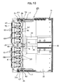
- the chuck mechanism 125 of the embodiment is configured in the above-mentioned manner. Accordingly, to carry out a charge-discharge test for the thin secondary battery 1 using the chuck mechanism 125, it suffices that a magazine (resin spacer) 127 in which multiple thin secondary batteries 1 are housed be moved closer to the chuck mechanism 125 as in Fig. 12 by moving means not shown. Note that the piston rod 35 of the air cylinder 36 should be retracted as in Fig. 4 at this time.
- one each of the multiple thin secondary batteries 1 is housed in each of housing chambers 131 segmented by multiple separation walls 129, in such a manner as to project the pairs of electrode terminals 5, 7 frontward.
- the magazine 127 is moved closer to the chuck mechanism 125, with the electrode terminals 5, 7 of the thin secondary battery 1 away from the chuck mechanism 125 by a distance equal to a stroke of the piston rod 35, such that the electrode terminals 5, 7 can later be inserted between the pairs of spread-open metal plates 103, 105 of the chuck member 101.
- the chuck members 101 have moved to a position where the chuck members 101 can nip the upper and lower electrode terminals 5, 7 of the thin secondary battery 1.
- the tip end sides of the metal plates 103, 105 are segmented by providing the slit 106 in each of the tip ends of the metal plates 103, 105 in the front-rear direction. For this reason, even if there is an assembly error or the like in the metal plates 103, 105, the peeling and nipping members 108 are surely pressed against the surfaces of the electrode terminals 5, 7 so that the irregularities 108c of the nipping surfaces may peel off the oxide film formed on the surfaces of the electrode terminals 5, 7.
- the chuck mechanism 125 of the embodiment when carrying out a charge-discharge test for the thin secondary battery 1 not only makes it possible to carry out the charge-discharge test for a large number of thin secondary batteries 1 at once, but also has the following advantage.
- the chuck mechanism 125 is configured such that only a simple mechanism of driving the air cylinder 36 to extend the piston rod 35 is required for the multiple pairs of rollers 89 of the roller holding member 37 to make the chuck members 101 (the multiple pairs of metal plates 1031, 105) of the chuck holding member 41 perform the chucking action.
- action controllability is improved significantly as compared to the conventional example disclosed in Patent Document 1.
- the use of the chuck mechanism 125 also has the following advantages. Specifically, since the mechanism is configured such that the pair of rollers 89 are used to close the metal plates 103, 105 of the chuck member 101 being spread open, opening and closing actions of the metal plates 103, 105 can be performed smoothly.
- the metal plates 103, 105 are segmented by providing the slit 106 in each of the tip ends of the metal plates 103, 105 in the front-rear direction, the metal plates 103, 105 (the peeling and nipping members 108) can surely nip the electrode terminals 5, 7 as well as can favorably peel off the oxide film on the surfaces of the electrode terminals 5, 7 by using the irregularities 110c, even if there is an assembly error or the like in the metal plates 103, 105.
- the roller holding member 37 is formed by disposing the multiple divided roller holding members 55 laterally in parallel
- the chuck holding member 41 is formed by disposing the multiple divided chuck holding members 57 laterally in parallel.
- the chuck mechanism 125 has an advantage that its maintenance is easy since the individual parts can be changed easily.
- the drive means is not limited to the air cylinder, but may be a motor or another actuator.
Landscapes
- Engineering & Computer Science (AREA)
- Manufacturing & Machinery (AREA)
- Chemical & Material Sciences (AREA)
- Chemical Kinetics & Catalysis (AREA)
- Electrochemistry (AREA)
- General Chemical & Material Sciences (AREA)
- Power Engineering (AREA)
- Secondary Cells (AREA)
- Battery Mounting, Suspending (AREA)
Abstract
Description
- The present invention relates to a mechanism for chucking electrode terminals, used in a charge-discharge test device for a plate-shaped thin secondary battery.
- A thin secondary battery 1 having a plate shape as in
Figs. 13 and 14 is used in many technical fields. The thin secondary battery 1 has a configuration in which a pair of sheet-shaped electrode terminals flat case 3 in one direction. - As in the case of a conventional secondary battery, after being produced in a factory, the thin secondary battery 1 undergoes several charge-discharge tests for quality inspection, and then only that of acceptable quality is shipped in a half-charged state as a product. Patent Document 1 discloses a charge-discharge and inspection system for thin secondary batteries of this type.
- The conventional example includes: a battery container in which multiple thin secondary batteries are housed and arranged in a certain direction by inserting electrode terminals of thin secondary batteries into multiple insertion holes formed in a bottom plate of the battery container; a chuck mechanism for chucking the electrode terminals projecting from the insertion holes of the battery container; a first action (elevating) mechanism for moving the chuck mechanism; and a second action (elevating) mechanism for driving the chuck mechanism. The conventional example is configured such that after placing and arranging the multiple thin secondary batteries in the battery container, the chuck mechanism is moved closer to the battery container by the first action mechanism and is then driven to chuck the electrode terminals by the second action mechanism.
-
- Patent Document 1: Japanese Patent Application Publication No.
2004-319334 - However, as mentioned earlier, the conventional example includes individual mechanisms for the first action (elevating) of moving the chuck mechanism closer to the battery container, and the second action (elevating) of chucking the electrode terminals by the chuck mechanism. Accordingly, the actions need to be controlled independently, which may complicate the action controllability.
- The present invention has been made in view of the above circumstances, and aims to provide a chuck mechanism of a charge-discharge test device for a thin secondary battery, the mechanism having excellent action controllability.
- To achieve the above objective, a chuck mechanism of a charge-discharge test device for a thin secondary battery according to the first aspect includes a chuck unit including: a chuck drive part which is movable in a direction toward a battery container body housing a thin secondary battery; and a chuck activation part which is located away from the chuck drive part in the direction toward the battery container body and whose movement in the same direction is restricted. In the chuck mechanism, when the chuck unit is moved in the direction toward the battery container body, the chuck drive part activates a chuck member of the chuck activation part whose movement in the same direction is restricted.
- In addition, according to the invention of the second aspect, in the chuck mechanism of a charge-discharge test device for a thin secondary battery according to the first aspect, the chuck drive part is a roller holding member formed to be movable in a front-rear direction of a supporting base by driving of drive means attached to the supporting base, and including on a front surface thereof multiple pairs of rollers rotatably disposed in parallel in a left-right direction of the supporting base; the chuck activation part is a chuck holding member attached in front of the roller holding member via a spring member, and including multiple chuck members each formed of a pair of strip-shaped metal plates which are inserted between the corresponding pair of rollers and whose tip end sides are spread open toward the front in a substantially V-shape in plan view; the supporting base includes a restriction part for restricting a forward movement of the chuck holding member; and the movement of the chuck holding member moved forward together with the roller holding member by the driving of the drive means is restricted by the restriction part, as well as the tip end sides of each of the chuck members inserted between the corresponding pair of rollers are closed by the corresponding pair of rollers when the roller holding member moves forward even further against a spring force of the spring member, so that each of the chuck members chucks an electrode terminal of each of thin secondary batteries housed in the battery container body in correspondence with the chuck members.
- Further, according to the invention of the third aspect, in the chuck mechanism of a charge-discharge test device for a thin secondary battery according to the second aspect, the roller holding member is formed by disposing multiple divided roller holding members in parallel on two upper and lower shafts arranged in the left-right direction of the supporting base; the chuck holding member is formed by disposing multiple divided chuck holding members in parallel on two upper and lower shafts arranged in the left-right direction of the supporting base; and the spring member extends between each of coupling brackets attached to left and right outer peripheries of the roller holding member and a corresponding one of coupling brackets attached to left and right outer peripheries of the chuck holding member.
- Further, according to the invention of the fourth aspect, in the chuck mechanism of a charge-discharge test device for a thin secondary battery according to the second aspect, an oxide film peeling and nipping member is attached to tip ends of the pair of metal plates. Furthermore, according to the invention of the fifth aspect, in the chuck mechanism of a charge-discharge test device for a thin secondary battery according to the fourth aspect, a slit is formed in the tip ends of the pair of metal plates in a front-rear direction, and the oxide film peeling and nipping member is attached to each of tip ends of each metal plate partitioned by the slit.
- According to the present invention, the operation of moving the chuck unit in the direction toward the battery container enables the chuck drive part to activate the chuck member of the chuck activation part to chuck a thin secondary battery. Hence, the present invention has an advantage of excellent action controllability.
-
- [
Fig. 1] Fig. 1 is a front perspective view of a chuck mechanism of an embodiment according to claims 1 to 5. - [
Fig. 2] Fig. 2 is a back perspective view of the chuck mechanism. - [
Fig. 3] Fig. 3 is a back perspective view of the chuck mechanism. - [
Fig. 4] Fig. 4 is a plan view of the chuck mechanism. - [
Fig. 5] Fig. 5 is a front perspective view of a divided roller holding member and a divided chuck holding member. - [
Fig. 6] Fig. 6 is a back perspective view of the divided roller holding member and the divided chuck holding member. - [
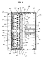
Fig. 7] Fig. 7 is a lateral view of the chuck mechanism. - [
Fig. 8] Fig. 8 is a plan view of the chuck mechanism. - [
Fig. 9] Fig. 9 is a lateral view of the chuck mechanism. - [
Fig. 10] Fig. 10 is a plan view of the chuck mechanism where chuck members are closed by rollers. - [
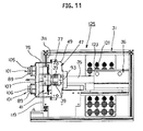
Fig. 11] Fig. 11 is a lateral view of the chuck mechanism where the chuck members are closed by the rollers. - [
Fig. 12] Fig. 12 is a plan view of the chuck mechanism and a magazine. - [
Fig. 13] Fig. 13 is a perspective view of a thin secondary battery. - [
Fig. 14] Fig. 14 is a plan view of the thin secondary battery. -
Figs. 1 to 12 show an embodiment of a chuck mechanism according to claims 1 to 5. InFigs. 1 to 3 ,reference sign 31 denotes a supporting base having a rectangular solid shape formed of 15columns 31 a to 31o arranged in the front, back, left, and right of the supportingbase 31. A supportingplate 33 covering an area between the center of the supportingbase 31 in a front-rear direction and a back portion side thereof is fixed on threecolumns 31i to 31k laid laterally across substantial centers of the left and right sides and a substantial center of the back side of thesupport base 31. As inFig. 4 , a double-acting air cylinder (drive means) 36 including apiston rod 35 extending and contracting in the front-rear direction of the supportingbase 31 is mounted in the center of the supportingplate 33. - Then, a roller holding member (chuck drive part) 37 including multiple pairs of
rollers 89 for activatingchuck members 101 of a later-mentioned chuck holding member (chuck activation part) 41 is attached to a tip end of thepiston rod 35, and thechuck holding member 41 is attached in front of theroller holding member 37 with two each of left andright coil springs 39 interposed between thechuck holding member 41 and theroller holding member 37. - Specifically, as in
Figs. 1 to 4 ,columnar guide members 43 are inserted in acasing 36a of theair cylinder 36 on the respective left and right sides of thepiston rod 35 along thepiston rod 35, and a thick plate-shaped coupling member 45 is fixed on tip ends of bothguide members 43 and of thepiston rod 35. Moreover, a long supportingbracket 47 substantially U-shaped in plan view for supporting theroller holding member 37 is attached to thecoupling member 45 in such a manner as to extend in the left-right direction of the supportingbase 31. Left andright flanges 49 of the supportingbracket 47 are bent in an L-shape toward the front of the supportingbase 31. - Additionally, the
roller holding member 37 is formed by disposing multiple dividedroller holding members 55 laterally in parallel on two upper andlower shafts right flanges 49. -
Figs. 5 and6 each show one of the dividedroller holding members 55 and a dividedchuck holding member 57. As mentioned earlier, theroller holding member 37 is formed by disposing the multiple dividedroller holding members 55 in parallel on theshafts chuck holding member 41 is formed by disposing multiple dividedchuck holding members 57 in parallel on two upper andlower shafts - As in
Figs. 5 and6 , first of all in the dividedroller holding member 55, two upper andlower block members single coupling plate 67. Ashaft insertion hole 69 into which theshaft 51 is inserted is formed in the center of theupper block member 63, and ashaft insertion hole 71 into which theshaft 53 is inserted is provided in the center of thelower block member 65.Tubular spacers 73 through which theshaft insertion holes block members - A pair of upper and
lower arm members 75 substantially L-shaped in cross section are respectively screwed on the front sides of theblock members roller attachment plate 81 in which upper and lowerrectangular openings 77, 79 are formed is integrally formed on tip ends of thearm members 75, and theroller attachment plate 81 is disposed to face thecoupling plate 67. - Moreover, a pair of
roller attachment brackets openings 77, 79 of theroller attachment plate 81, and an even number ofroller attachment holes 87 are provided at equal intervals on tip end sides of each of theroller attachment brackets roller attachment holes 87 face each other. In addition, the multiple pairs of rollers 89 (four pairs on each of the upper and lower pairs of brackets in the embodiment) are rotatably attached to theroller attachment holes 87 between the upper and lower pairs ofroller attachment brackets - The divided
roller holding member 55 is thus configured, and as mentioned earlier, the two upper andlower shafts right flanges 49 of the supportingbracket 47 are inserted into the upper and lowershaft insertion holes 71 of each of the divided roller holding members 55 (block member 63, 65). As inFigs. 2 and3 , the twoshafts members 91 extending frontward from the centers of upper and lower parts of the supportingbracket 47, respectively. On left and right sides of theholding members 91, four each of the dividedroller holding members 55 are disposed in parallel between theshafts spacers 73 interposed therebetween. Theroller holding member 37 is supported by the supportingbracket 47. Additionally, a coupling bracket 93 L-shaped in cross section is attached to an outer periphery of each of the left andright flanges 49. - Next, a description is given of a configuration of the
chuck holding member 41. As inFig. 1 , thechuck holding member 41 also has a configuration in which the multiple dividedchuck holding members 57 are disposed laterally in parallel on the two upper andlower shafts base 31. - As in
Figs. 5 and6 , the dividedchuck holding member 57 is paired with the dividedroller holding member 55 to form a unit, and thus theroller holding member 37 and thechuck holding member 41 form a chuck unit as a whole. - In the drawings,
reference sign 95 denotes a thick plate-shaped chuck attachment member disposed along theroller attachment plate 81 between thearm members 75, and theshafts base 31. Then, the multiple (four each in upper and lower parts of thechuck attachment member 95 in the embodiment)chuck members 101 are disposed laterally in parallel in upper and lower rows in correspondence with the aforementioned pairs ofrollers 89, in upper and lower parts of a front surface of thechuck attachment member 95. - As shown in the drawings, the
chuck member 101 is formed of a pair of strip-shapedmetal plates metal plates chuck attachment member 95. The back end of onemetal plate 103 projecting from a back surface of thechuck attachment member 95 is bent in an L-shape along the back surface of thechuck attachment member 95, and screwed onto the back surface. Similarly, the back end of theother metal plate 105 projecting from the back surface of thechuck attachment member 95 is bent in an L-shape along the back surface of thechuck attachment member 95, and screwed onto the back surface. As inFig. 6 , the back ends of themetal plates chuck attachment member 95. Moreover, wires of a charge-discharge test device can be connected to the back ends of themetal plates chuck attachment member 95. - Additionally, the aforementioned pair of
rollers 89 are disposed in correspondence with each chuck member 101 (themetal plates 103, 105) projecting toward the front of thechuck attachment member 95, and each pair ofmetal plates rollers 89. - As in
Fig. 5 , the tip end sides of themetal plates rollers 89 spread open in a substantially V-shape in plan view, and the tip ends thereof are bent slightly inward. As will be mentioned later, when theroller holding member 37 is moved forward by driving of theair cylinder 36, themetal plates 103, 105 (the chuck member 101) being spread open in the substantially V-shape in plan view are closed by the pair ofrollers 89. - In addition, a
slit 106 is formed in the front-rear direction at the tip end of each of themetal plates Fig. 5 , a pair of oxide film peeling and nipping members (hereinafter refered to as "peeling and nipping members") 108 are fixed by riveting, on the tip end sides of themetal plates slit 106. - Specifically, as in
Fig. 1 , anattachment hole 110 to which the peeling and nippingmember 108 is fixed by riveting is provided on the tip end side of each of themetal plates slit 106. As inFig. 5 , the peeling and nippingmember 108 is formed of aleg member 108a fixed by riveting to theattachment hole 110, and a thick disk-shapedhead portion 108b having a circular shape in plan view integrally formed with theleg member 108a. Moreover,irregularities 108c are formed by knurling on a nipping surface which is a top part of thehead portion 108b. As will be mentioned later, when themetal plates rollers 89 with theelectrode terminals metal plates irregularities 108c of the pair of peeling and nippingmembers 108 are pressed against the front and back sides of theelectrode terminals electrode terminals - The
chuck member 101 is configured in the above-mentioned manner, and as has been described, the fourchuck members 101 are disposed laterally in parallel at upper and lower parts of the front surface of thechuck attachment member 95. Additionally, thechuck holding member 41 is formed by disposing the dividedchuck holding members 57 in parallel between the twoshafts roller holding members 55. - As in
Figs. 1 to 3 , a coupling bracket 107 L-shaped in cross section is attached to projecting ends of theshafts chuck holding members 57. - The
coupling brackets 107 and thecoupling brackets 93 are held to be movable in the front-rear direction of the supportingbase 31 byguide members 109 attached on left and right sides of the supportingbase 31. Oneguide member 109 is supported by a plate 111 which is attached among thecolumns base 31, and theother guide member 109 is supported by aplate 113 which is attached among thecolumns base 31. - Moreover, as in
Fig. 1 , twoshafts 117 inserted through upper and lower shaft insertion holes 115 provided in eachcoupling bracket 107 are attached to the correspondingcoupling bracket 93 in parallel. Additionally, the coil spring (spring member) 39 is wound around each of theshafts 117. As inFigs. 1 to 7 , when thepiston rod 35 of theair cylinder 36 is retracted, thechuck member 101 is inserted between therollers 89, the tip end sides of thechuck member 101 are spread open in the V-shape, and thechuck holding member 41 is located away from theroller holding member 37 at the front thereof by a spring force of thecoil spring 39. - Note that in this state, the
chuck member 101 is disposed inside the supportingbase 31 as inFigs. 4 and7 . - Then, when the
air cylinder 36 is driven and thepiston rod 35 extends forward from the state inFigs. 1 to 7 , theroller holding member 37 attached to thepiston rod 35 and thechuck holding member 41 attached to theroller holding member 37 are moved forward. As inFigs. 8 and9 , when thecoupling brackets 107 attached to the left and right outer peripheries of thechuck holding member 41 reach the left andright columns base 31, thecoupling brackets 107 come into contact with the columns (restriction parts) 311, 31m to restrict forward movement of thechuck holding member 41. - Additionally, as in
Fig. 1 , a column 119 (restriction part) is installed to vertically bridge thecolumns base 31 at the centers thereof. When the left andright coupling brackets 107 come into contact with thecolumns shafts column 119 to restrict forward movement of thechuck holding member 41. - When forward movement of the
chuck holding member 41 is thus restricted, thechuck members 101 project toward the front of the supportingbase 31 as inFigs. 8 and9 . - Besides, such restriction on the forward movement of the
chuck holding member 41 does not hinder driving of theair cylinder 36 at all, and thepiston rod 35 extends even further. With this, theroller holding member 37 moves even further forward against the spring force of the left and right coil springs 39 as inFigs. 10 and11 , causing the pairs ofrollers 89 to move forward. Hence, themetal plates chuck member 101 being spread open in the substantially V-shape in plan view are closed by the corresponding pair ofrollers 89, the pairs of peeling and nippingmembers 108 attached on the tip ends of themetal plates piston rod 35 stops its extension at this position. - Incidentally, in the drawings,
reference signs metal plates chuck attachment member 95. - The
chuck mechanism 125 of the embodiment is configured in the above-mentioned manner. Accordingly, to carry out a charge-discharge test for the thin secondary battery 1 using thechuck mechanism 125, it suffices that a magazine (resin spacer) 127 in which multiple thin secondary batteries 1 are housed be moved closer to thechuck mechanism 125 as inFig. 12 by moving means not shown. Note that thepiston rod 35 of theair cylinder 36 should be retracted as inFig. 4 at this time. - As in
Fig. 12 , in themagazine 127, one each of the multiple thin secondary batteries 1 is housed in each ofhousing chambers 131 segmented bymultiple separation walls 129, in such a manner as to project the pairs ofelectrode terminals magazine 127 is moved closer to thechuck mechanism 125, with theelectrode terminals chuck mechanism 125 by a distance equal to a stroke of thepiston rod 35, such that theelectrode terminals open metal plates chuck member 101. - Then, when the
air cylinder 36 is driven while the wires of the charge-discharge test device are connected to the back ends of themetal plates chuck attachment member 95, thepiston rod 35 extends forward, and theroller holding member 37 as well as thechuck holding member 41 attached to theroller holding member 37 are moved forward. - Thereafter, when the
chuck holding member 41 thus moves, thecoupling brackets 107 attached to left and right sides of thechuck holding member 41 come into contact with the left andright columns base 31, and theshafts column 119 to restrict forward movement of thechuck holding member 41. - At this time, as in
Fig. 12 , thechuck members 101 have moved to a position where thechuck members 101 can nip the upper andlower electrode terminals - Further, such restriction on the movement of the
chuck holding member 41 does not hinder driving of theair cylinder 36 at all, and thepiston rod 35 extends even further. Accordingly, theroller holding member 37 moves even further forward against the spring force of the left and right coil springs 39 as inFigs. 10 and11 , causing the pairs ofrollers 89 to move forward. Hence, themetal plates chuck member 101 being spread open in the substantially V-shape in plan view are closed by the corresponding pair ofrollers 89. Thus, the peeling and nippingmembers 108 attached on the tip ends of themetal plates lower electrode terminals - In the embodiment, the tip end sides of the
metal plates slit 106 in each of the tip ends of themetal plates metal plates members 108 are surely pressed against the surfaces of theelectrode terminals irregularities 108c of the nipping surfaces may peel off the oxide film formed on the surfaces of theelectrode terminals - Thereafter, electricity is supplied through the wires of the charge-discharge test connected to the back end side of the chuck member 101 (the
metal plates 103, 105), and the charge-discharge test for the thin secondary batteries 1 nipped by thechuck members 101 is started. - Then, after completion of the test, the
piston rod 35 of theair cylinder 36 is retracted to move theroller holding member 37 and thechuck holding member 41 backward. With this, themetal plates chuck member 101 which were closed by theroller 89 are spread open again, and are separated from theelectrode terminals - Thus, use of the
chuck mechanism 125 of the embodiment when carrying out a charge-discharge test for the thin secondary battery 1 not only makes it possible to carry out the charge-discharge test for a large number of thin secondary batteries 1 at once, but also has the following advantage. Specifically, thechuck mechanism 125 is configured such that only a simple mechanism of driving theair cylinder 36 to extend thepiston rod 35 is required for the multiple pairs ofrollers 89 of theroller holding member 37 to make the chuck members 101 (the multiple pairs of metal plates 1031, 105) of thechuck holding member 41 perform the chucking action. Thus, action controllability is improved significantly as compared to the conventional example disclosed in Patent Document 1. - The use of the
chuck mechanism 125 also has the following advantages. Specifically, since the mechanism is configured such that the pair ofrollers 89 are used to close themetal plates chuck member 101 being spread open, opening and closing actions of themetal plates metal plates slit 106 in each of the tip ends of themetal plates metal plates 103, 105 (the peeling and nipping members 108) can surely nip theelectrode terminals electrode terminals metal plates - Furthermore, the
roller holding member 37 is formed by disposing the multiple dividedroller holding members 55 laterally in parallel, and thechuck holding member 41 is formed by disposing the multiple dividedchuck holding members 57 laterally in parallel. Hence, thechuck mechanism 125 has an advantage that its maintenance is easy since the individual parts can be changed easily. - Note that although the embodiment uses the
air cylinder 36 as the drive means for moving theroller holding member 37 and other components forward and backward, the drive means is not limited to the air cylinder, but may be a motor or another actuator. -
1 thin secondary battery 5, 7 electrode terminal 31 supporting base 31a to 31o, 119 column 33 supporting plate 35 piston rod 36 air cylinder 37 roller holding member 39 coil spring 41 chuck holding member 43, 109 guide member 45 coupling member 47 supporting bracket 51, 53, 59, 61 shaft 55 divided roller holding member 57 divided chuck holding member 63, 65 block member 67 coupling plate 69, 71, 97, 99, 115 shaft insertion hole 75 arm member 81 roller attachment plate 83, 85 roller attachment bracket 87 roller attachment hole 89 roller 91 holding member 93, 107 coupling bracket 95 chuck attachment member 101 chuck member 103, 105 metal plate 106 slit 108 peeling and nipping member 111, 113 plate 117 shaft 125 chuck mechanism 127 magazine
Claims (5)
- A chuck mechanism of a charge-discharge test device for a thin secondary battery, comprising a chuck unit including:a chuck drive part which is movable in a direction toward a battery container body housing a thin secondary battery; anda chuck activation part which is located away from the chuck drive part in the direction toward the battery container body and whose movement in the same direction is restricted, whereinwhen the chuck unit is moved in the direction toward the battery container body, the chuck drive part activates a chuck member of the chuck activation part whose movement in the same direction is restricted.
- The chuck mechanism of a charge-discharge test device for a thin secondary battery according to claim 1, wherein:the chuck drive part is a roller holding member formed to be movable in a front-rear direction of a supporting base by driving of drive means attached to the supporting base, and including on a front surface thereof a plurality of pairs of rollers rotatably disposed in parallel in a left-right direction of the supporting base;the chuck activation part is a chuck holding member attached in front of the roller holding member via a spring member, and including a plurality of chuck members each formed of a pair of strip-shaped metal plates which are inserted between the corresponding pair of rollers and whose tip end sides are spread open toward the front in a substantially V-shape in plan view;the supporting base includes a restriction part for restricting a forward movement of the chuck holding member; andthe movement of the chuck holding member moved forward together with the roller holding member by the driving of the drive means is restricted by the restriction part, as well asthe tip end sides of each of the chuck members inserted between the corresponding pair of rollers are closed by the corresponding pair of rollers when the roller holding member moves forward even further against a spring force of the spring member,so that each of the chuck members chucks an electrode terminal of each of thin secondary batteries housed in the battery container body in correspondence with the chuck members.
- The chuck mechanism of a charge-discharge test device for a thin secondary battery according to claim 2, wherein:the roller holding member is formed by disposing a plurality of divided roller holding members in parallel on two upper and lower shafts arranged in the left-right direction of the supporting base;the chuck holding member is formed by disposing a plurality of divided chuck holding members in parallel on two upper and lower shafts arranged in the left-right direction of the supporting base; andthe spring member extends between each of coupling brackets attached to left and right outer peripheries of the roller holding member and a corresponding one of coupling brackets attached to left and right outer peripheries of the chuck holding member.
- The chuck mechanism of a charge-discharge test device for a thin secondary battery according to claim 2, wherein an oxide film peeling and nipping member is attached to tip ends of the pair of metal plates.
- The chuck mechanism of a charge-discharge test device for a thin secondary battery according to claim 4, wherein a slit is formed in the tip ends of the pair of metal plates in a front-rear direction, and the oxide film peeling and nipping member is attached to each of tip ends of each metal plate partitioned by the slit.
Applications Claiming Priority (2)
| Application Number | Priority Date | Filing Date | Title |
|---|---|---|---|
| JP2010158910A JP5498289B2 (en) | 2010-07-13 | 2010-07-13 | Chuck mechanism of charge / discharge test equipment for thin secondary batteries |
| PCT/JP2011/003497 WO2012008095A1 (en) | 2010-07-13 | 2011-06-20 | Chuck mechanism of charge-discharge test device for thin secondary battery |
Publications (3)
| Publication Number | Publication Date |
|---|---|
| EP2595237A1 true EP2595237A1 (en) | 2013-05-22 |
| EP2595237A4 EP2595237A4 (en) | 2016-11-02 |
| EP2595237B1 EP2595237B1 (en) | 2017-08-09 |
Family
ID=45469115
Family Applications (1)
| Application Number | Title | Priority Date | Filing Date |
|---|---|---|---|
| EP11806432.8A Active EP2595237B1 (en) | 2010-07-13 | 2011-06-20 | Chuck mechanism of charge-discharge test device for thin secondary battery |
Country Status (6)
| Country | Link |
|---|---|
| US (1) | US9136567B2 (en) |
| EP (1) | EP2595237B1 (en) |
| JP (1) | JP5498289B2 (en) |
| KR (1) | KR101361411B1 (en) |
| CN (1) | CN103038932B (en) |
| WO (1) | WO2012008095A1 (en) |
Families Citing this family (16)
| Publication number | Priority date | Publication date | Assignee | Title |
|---|---|---|---|---|
| JP2014102883A (en) * | 2012-11-16 | 2014-06-05 | Fujitsu Telecom Networks Ltd | Chuck device |
| CN103904372A (en) * | 2012-12-28 | 2014-07-02 | 深圳市沃特玛电池有限公司 | Capacity grading cabinet for groups of lithium batteries |
| WO2014178236A1 (en) * | 2013-05-01 | 2014-11-06 | 日産自動車株式会社 | Charging and discharging inspection device and charging and discharging inspection method for thin secondary battery |
| KR101509206B1 (en) * | 2013-07-23 | 2015-04-10 | (주)이티에이치 | Secondary battery charge and discharge jig with improved grippre exchange structure |
| JP6233105B2 (en) * | 2014-03-07 | 2017-11-22 | 株式会社富士通テレコムネットワークス福島 | Energized chucking durability test equipment |
| JP6268013B2 (en) * | 2014-03-20 | 2018-01-24 | オートモーティブエナジーサプライ株式会社 | Electrode terminal shape correcting device and electrode terminal shape correcting method |
| US10161963B2 (en) * | 2015-08-17 | 2018-12-25 | Chaojiong Zhang | Electrical contact and testing apparatus |
| CN105826486B (en) * | 2016-04-29 | 2018-08-17 | 无锡港盛重型装备有限公司 | A kind of protective device of accumulator |
| CN106328979A (en) * | 2016-08-31 | 2017-01-11 | 无锡东恒新能源科技有限公司 | Fast assembling equipment for lithium battery |
| JP6800419B2 (en) * | 2017-02-03 | 2020-12-16 | 株式会社エンビジョンAescジャパン | Chuck device |
| DE102017203957A1 (en) | 2017-03-10 | 2018-09-13 | Thyssenkrupp Ag | Formation plant and method for delivery to a formation plant |
| CN107369845B (en) * | 2017-07-26 | 2023-05-05 | 深圳市嘉熠精密自动化科技有限公司 | A battery automatic charging system |
| KR101873709B1 (en) * | 2018-02-21 | 2018-07-03 | 주식회사 에스에이치엘 | Secondary battery cell pouch gripper and transferring the same |
| WO2020153742A1 (en) * | 2019-01-24 | 2020-07-30 | 주식회사 고영테크놀러지 | Transfer apparatus for testing device, testing device and object testing method using same |
| SE2151463A1 (en) * | 2021-12-01 | 2022-12-27 | Northvolt Ab | Pre-fabricated movable walk-in chamber for testing secondary cells |
| CN119375712B (en) * | 2024-12-31 | 2025-03-21 | 安可捷检测(常州)有限公司 | A power lithium battery pack extrusion test device |
Family Cites Families (14)
| Publication number | Priority date | Publication date | Assignee | Title |
|---|---|---|---|---|
| US3729799A (en) * | 1971-10-21 | 1973-05-01 | Gen Battery Corp | Battery testing and crimping device |
| JPS61109191U (en) * | 1984-12-24 | 1986-07-10 | ||
| JPH1116615A (en) | 1997-06-23 | 1999-01-22 | Tokyo Gas Co Ltd | Fitting |
| JP2002134176A (en) * | 2000-10-30 | 2002-05-10 | Mikuni Kogyo:Kk | Charge / discharge / inspection mechanism for lithium polymer batteries |
| JP4536250B2 (en) | 2000-11-30 | 2010-09-01 | 株式会社ユタカ電機製作所 | Supply / discharge test equipment using clip for energization |
| JP2002298929A (en) * | 2001-03-30 | 2002-10-11 | Japan System Engineering Kk | Inspection equipment for polymer laminated secondary batteries |
| JP3971324B2 (en) | 2003-02-25 | 2007-09-05 | 日本碍子株式会社 | Energizing terminal gripper and gripper drive hand |
| JP2004319334A (en) | 2003-04-17 | 2004-11-11 | Nittetsu Elex Co Ltd | Charging/discharging and inspection system of flat battery |
| US7129706B2 (en) * | 2003-06-11 | 2006-10-31 | Bright Solutions, Inc. | Part tester and method |
| US7417437B1 (en) * | 2005-03-24 | 2008-08-26 | Torres Felix H | Vehicle battery testing assembly |
| US8026698B2 (en) * | 2006-02-09 | 2011-09-27 | Scheucher Karl F | Scalable intelligent power supply system and method |
| JP5252836B2 (en) * | 2007-05-29 | 2013-07-31 | 三洋電機株式会社 | Pack battery |
| CN101654077B (en) * | 2008-08-18 | 2012-08-29 | 纬创资通股份有限公司 | Holding device with charging function |
| CN201387923Y (en) * | 2008-12-19 | 2010-01-20 | 天津力神电池股份有限公司 | Novel battery charging-discharging plate holder |
-
2010
- 2010-07-13 JP JP2010158910A patent/JP5498289B2/en active Active
-
2011
- 2011-06-20 EP EP11806432.8A patent/EP2595237B1/en active Active
- 2011-06-20 KR KR1020137000803A patent/KR101361411B1/en active Active
- 2011-06-20 CN CN201180034642.8A patent/CN103038932B/en active Active
- 2011-06-20 WO PCT/JP2011/003497 patent/WO2012008095A1/en not_active Ceased
- 2011-06-20 US US13/809,770 patent/US9136567B2/en active Active
Also Published As
| Publication number | Publication date |
|---|---|
| KR101361411B1 (en) | 2014-02-10 |
| EP2595237A4 (en) | 2016-11-02 |
| EP2595237B1 (en) | 2017-08-09 |
| CN103038932B (en) | 2015-11-25 |
| CN103038932A (en) | 2013-04-10 |
| KR20130030805A (en) | 2013-03-27 |
| US9136567B2 (en) | 2015-09-15 |
| JP5498289B2 (en) | 2014-05-21 |
| US20130113494A1 (en) | 2013-05-09 |
| WO2012008095A1 (en) | 2012-01-19 |
| JP2012022847A (en) | 2012-02-02 |
Similar Documents
| Publication | Publication Date | Title |
|---|---|---|
| EP2595237B1 (en) | Chuck mechanism of charge-discharge test device for thin secondary battery | |
| EP2398089B1 (en) | Chuck mechanism of charge/discharge testing device for flat-rechargeable batteries | |
| EP2993725B1 (en) | Charging and discharging inspection device and charging and discharging inspection method for thin secondary battery | |
| CN104064702B (en) | Cell apparatus | |
| EP4501545A1 (en) | Tray and tray device | |
| US20070196719A1 (en) | Device for assembling a banded fuel cell stack | |
| WO2014087959A1 (en) | Power supply device | |
| KR101923935B1 (en) | Clamp-type probe device | |
| JP2012252848A (en) | Electric power source element holding tool and electric power source element holding tray | |
| KR101243914B1 (en) | Manufacturing apparatus of battery pack | |
| EP4354571A1 (en) | Battery module manufacturing clamping assembly and method of clamping a battery pallet for welding | |
| US11316187B2 (en) | Fuel cell stack assembly apparatus and method | |
| CN103229331B (en) | Battery assembling device and battery assembly method | |
| JP2003059543A (en) | Charge / discharge device | |
| JP2016126846A (en) | Assembly jig and assembly method | |
| CN102832361B (en) | Bracket | |
| CN220316555U (en) | Clamping device | |
| CN219852693U (en) | Pressure head mechanism and welding auxiliary device | |
| CN222483239U (en) | Positioning fixture | |
| CN111564748A (en) | Fine terminal assembling equipment | |
| CN224185341U (en) | Cover plate handling device and battery assembly equipment | |
| CN116175146B (en) | Assembly device and method | |
| JP6268013B2 (en) | Electrode terminal shape correcting device and electrode terminal shape correcting method | |
| CN119170849A (en) | Soft packet of battery press machine equipment | |
| JP2018106966A (en) | Lamination device |
Legal Events
| Date | Code | Title | Description |
|---|---|---|---|
| PUAI | Public reference made under article 153(3) epc to a published international application that has entered the european phase |
Free format text: ORIGINAL CODE: 0009012 |
|
| 17P | Request for examination filed |
Effective date: 20130122 |
|
| AK | Designated contracting states |
Kind code of ref document: A1 Designated state(s): AL AT BE BG CH CY CZ DE DK EE ES FI FR GB GR HR HU IE IS IT LI LT LU LV MC MK MT NL NO PL PT RO RS SE SI SK SM TR |
|
| DAX | Request for extension of the european patent (deleted) | ||
| RA4 | Supplementary search report drawn up and despatched (corrected) |
Effective date: 20160930 |
|
| RIC1 | Information provided on ipc code assigned before grant |
Ipc: G01R 31/36 20060101ALI20160926BHEP Ipc: H01M 10/42 20060101AFI20160926BHEP |
|
| REG | Reference to a national code |
Ref country code: DE Ref legal event code: R079 Ref document number: 602011040478 Country of ref document: DE Free format text: PREVIOUS MAIN CLASS: H01M0010440000 Ipc: H01M0010420000 |
|
| GRAP | Despatch of communication of intention to grant a patent |
Free format text: ORIGINAL CODE: EPIDOSNIGR1 |
|
| RIC1 | Information provided on ipc code assigned before grant |
Ipc: H01M 10/42 20060101AFI20170131BHEP Ipc: G01R 31/36 20060101ALI20170131BHEP |
|
| INTG | Intention to grant announced |
Effective date: 20170221 |
|
| RIN1 | Information on inventor provided before grant (corrected) |
Inventor name: OKAZAKI, TSUTOMU Inventor name: NIWA, YOSHIKAZU Inventor name: KAWASAKI, TAKAHIRO Inventor name: NISHIHARA, TAKASHI Inventor name: YASOOKA, TAKESHI |
|
| GRAS | Grant fee paid |
Free format text: ORIGINAL CODE: EPIDOSNIGR3 |
|
| GRAA | (expected) grant |
Free format text: ORIGINAL CODE: 0009210 |
|
| AK | Designated contracting states |
Kind code of ref document: B1 Designated state(s): AL AT BE BG CH CY CZ DE DK EE ES FI FR GB GR HR HU IE IS IT LI LT LU LV MC MK MT NL NO PL PT RO RS SE SI SK SM TR |
|
| REG | Reference to a national code |
Ref country code: GB Ref legal event code: FG4D |
|
| REG | Reference to a national code |
Ref country code: CH Ref legal event code: EP Ref country code: AT Ref legal event code: REF Ref document number: 917752 Country of ref document: AT Kind code of ref document: T Effective date: 20170815 |
|
| REG | Reference to a national code |
Ref country code: IE Ref legal event code: FG4D |
|
| REG | Reference to a national code |
Ref country code: DE Ref legal event code: R096 Ref document number: 602011040478 Country of ref document: DE |
|
| REG | Reference to a national code |
Ref country code: NL Ref legal event code: MP Effective date: 20170809 |
|
| REG | Reference to a national code |
Ref country code: LT Ref legal event code: MG4D |
|
| REG | Reference to a national code |
Ref country code: AT Ref legal event code: MK05 Ref document number: 917752 Country of ref document: AT Kind code of ref document: T Effective date: 20170809 |
|
| PG25 | Lapsed in a contracting state [announced via postgrant information from national office to epo] |
Ref country code: SE Free format text: LAPSE BECAUSE OF FAILURE TO SUBMIT A TRANSLATION OF THE DESCRIPTION OR TO PAY THE FEE WITHIN THE PRESCRIBED TIME-LIMIT Effective date: 20170809 Ref country code: LT Free format text: LAPSE BECAUSE OF FAILURE TO SUBMIT A TRANSLATION OF THE DESCRIPTION OR TO PAY THE FEE WITHIN THE PRESCRIBED TIME-LIMIT Effective date: 20170809 Ref country code: NL Free format text: LAPSE BECAUSE OF FAILURE TO SUBMIT A TRANSLATION OF THE DESCRIPTION OR TO PAY THE FEE WITHIN THE PRESCRIBED TIME-LIMIT Effective date: 20170809 Ref country code: FI Free format text: LAPSE BECAUSE OF FAILURE TO SUBMIT A TRANSLATION OF THE DESCRIPTION OR TO PAY THE FEE WITHIN THE PRESCRIBED TIME-LIMIT Effective date: 20170809 Ref country code: AT Free format text: LAPSE BECAUSE OF FAILURE TO SUBMIT A TRANSLATION OF THE DESCRIPTION OR TO PAY THE FEE WITHIN THE PRESCRIBED TIME-LIMIT Effective date: 20170809 Ref country code: HR Free format text: LAPSE BECAUSE OF FAILURE TO SUBMIT A TRANSLATION OF THE DESCRIPTION OR TO PAY THE FEE WITHIN THE PRESCRIBED TIME-LIMIT Effective date: 20170809 Ref country code: NO Free format text: LAPSE BECAUSE OF FAILURE TO SUBMIT A TRANSLATION OF THE DESCRIPTION OR TO PAY THE FEE WITHIN THE PRESCRIBED TIME-LIMIT Effective date: 20171109 |
|
| PG25 | Lapsed in a contracting state [announced via postgrant information from national office to epo] |
Ref country code: LV Free format text: LAPSE BECAUSE OF FAILURE TO SUBMIT A TRANSLATION OF THE DESCRIPTION OR TO PAY THE FEE WITHIN THE PRESCRIBED TIME-LIMIT Effective date: 20170809 Ref country code: BG Free format text: LAPSE BECAUSE OF FAILURE TO SUBMIT A TRANSLATION OF THE DESCRIPTION OR TO PAY THE FEE WITHIN THE PRESCRIBED TIME-LIMIT Effective date: 20171109 Ref country code: ES Free format text: LAPSE BECAUSE OF FAILURE TO SUBMIT A TRANSLATION OF THE DESCRIPTION OR TO PAY THE FEE WITHIN THE PRESCRIBED TIME-LIMIT Effective date: 20170809 Ref country code: GR Free format text: LAPSE BECAUSE OF FAILURE TO SUBMIT A TRANSLATION OF THE DESCRIPTION OR TO PAY THE FEE WITHIN THE PRESCRIBED TIME-LIMIT Effective date: 20171110 Ref country code: RS Free format text: LAPSE BECAUSE OF FAILURE TO SUBMIT A TRANSLATION OF THE DESCRIPTION OR TO PAY THE FEE WITHIN THE PRESCRIBED TIME-LIMIT Effective date: 20170809 Ref country code: IS Free format text: LAPSE BECAUSE OF FAILURE TO SUBMIT A TRANSLATION OF THE DESCRIPTION OR TO PAY THE FEE WITHIN THE PRESCRIBED TIME-LIMIT Effective date: 20171209 Ref country code: PL Free format text: LAPSE BECAUSE OF FAILURE TO SUBMIT A TRANSLATION OF THE DESCRIPTION OR TO PAY THE FEE WITHIN THE PRESCRIBED TIME-LIMIT Effective date: 20170809 |
|
| PG25 | Lapsed in a contracting state [announced via postgrant information from national office to epo] |
Ref country code: DK Free format text: LAPSE BECAUSE OF FAILURE TO SUBMIT A TRANSLATION OF THE DESCRIPTION OR TO PAY THE FEE WITHIN THE PRESCRIBED TIME-LIMIT Effective date: 20170809 Ref country code: RO Free format text: LAPSE BECAUSE OF FAILURE TO SUBMIT A TRANSLATION OF THE DESCRIPTION OR TO PAY THE FEE WITHIN THE PRESCRIBED TIME-LIMIT Effective date: 20170809 Ref country code: CZ Free format text: LAPSE BECAUSE OF FAILURE TO SUBMIT A TRANSLATION OF THE DESCRIPTION OR TO PAY THE FEE WITHIN THE PRESCRIBED TIME-LIMIT Effective date: 20170809 |
|
| REG | Reference to a national code |
Ref country code: DE Ref legal event code: R097 Ref document number: 602011040478 Country of ref document: DE |
|
| REG | Reference to a national code |
Ref country code: FR Ref legal event code: PLFP Year of fee payment: 8 |
|
| PG25 | Lapsed in a contracting state [announced via postgrant information from national office to epo] |
Ref country code: SK Free format text: LAPSE BECAUSE OF FAILURE TO SUBMIT A TRANSLATION OF THE DESCRIPTION OR TO PAY THE FEE WITHIN THE PRESCRIBED TIME-LIMIT Effective date: 20170809 Ref country code: IT Free format text: LAPSE BECAUSE OF FAILURE TO SUBMIT A TRANSLATION OF THE DESCRIPTION OR TO PAY THE FEE WITHIN THE PRESCRIBED TIME-LIMIT Effective date: 20170809 Ref country code: EE Free format text: LAPSE BECAUSE OF FAILURE TO SUBMIT A TRANSLATION OF THE DESCRIPTION OR TO PAY THE FEE WITHIN THE PRESCRIBED TIME-LIMIT Effective date: 20170809 Ref country code: SM Free format text: LAPSE BECAUSE OF FAILURE TO SUBMIT A TRANSLATION OF THE DESCRIPTION OR TO PAY THE FEE WITHIN THE PRESCRIBED TIME-LIMIT Effective date: 20170809 |
|
| PLBE | No opposition filed within time limit |
Free format text: ORIGINAL CODE: 0009261 |
|
| STAA | Information on the status of an ep patent application or granted ep patent |
Free format text: STATUS: NO OPPOSITION FILED WITHIN TIME LIMIT |
|
| 26N | No opposition filed |
Effective date: 20180511 |
|
| PG25 | Lapsed in a contracting state [announced via postgrant information from national office to epo] |
Ref country code: SI Free format text: LAPSE BECAUSE OF FAILURE TO SUBMIT A TRANSLATION OF THE DESCRIPTION OR TO PAY THE FEE WITHIN THE PRESCRIBED TIME-LIMIT Effective date: 20170809 |
|
| REG | Reference to a national code |
Ref country code: CH Ref legal event code: PL |
|
| REG | Reference to a national code |
Ref country code: BE Ref legal event code: MM Effective date: 20180630 |
|
| REG | Reference to a national code |
Ref country code: IE Ref legal event code: MM4A |
|
| PG25 | Lapsed in a contracting state [announced via postgrant information from national office to epo] |
Ref country code: LU Free format text: LAPSE BECAUSE OF NON-PAYMENT OF DUE FEES Effective date: 20180620 Ref country code: MC Free format text: LAPSE BECAUSE OF FAILURE TO SUBMIT A TRANSLATION OF THE DESCRIPTION OR TO PAY THE FEE WITHIN THE PRESCRIBED TIME-LIMIT Effective date: 20170809 |
|
| PG25 | Lapsed in a contracting state [announced via postgrant information from national office to epo] |
Ref country code: IE Free format text: LAPSE BECAUSE OF NON-PAYMENT OF DUE FEES Effective date: 20180620 Ref country code: CH Free format text: LAPSE BECAUSE OF NON-PAYMENT OF DUE FEES Effective date: 20180630 Ref country code: LI Free format text: LAPSE BECAUSE OF NON-PAYMENT OF DUE FEES Effective date: 20180630 |
|
| PG25 | Lapsed in a contracting state [announced via postgrant information from national office to epo] |
Ref country code: BE Free format text: LAPSE BECAUSE OF NON-PAYMENT OF DUE FEES Effective date: 20180630 |
|
| REG | Reference to a national code |
Ref country code: DE Ref legal event code: R082 Ref document number: 602011040478 Country of ref document: DE Representative=s name: HOEFER & PARTNER PATENTANWAELTE MBB, DE Ref country code: DE Ref legal event code: R081 Ref document number: 602011040478 Country of ref document: DE Owner name: ENVISION AESC JAPAN LTD., ZAMA-SHI, JP Free format text: FORMER OWNER: NISSAN MOTOR CO., LTD., YOKOHAMA-SHI, KANAGAWA, JP |
|
| PG25 | Lapsed in a contracting state [announced via postgrant information from national office to epo] |
Ref country code: MT Free format text: LAPSE BECAUSE OF NON-PAYMENT OF DUE FEES Effective date: 20180620 |
|
| PG25 | Lapsed in a contracting state [announced via postgrant information from national office to epo] |
Ref country code: TR Free format text: LAPSE BECAUSE OF FAILURE TO SUBMIT A TRANSLATION OF THE DESCRIPTION OR TO PAY THE FEE WITHIN THE PRESCRIBED TIME-LIMIT Effective date: 20170809 |
|
| PG25 | Lapsed in a contracting state [announced via postgrant information from national office to epo] |
Ref country code: HU Free format text: LAPSE BECAUSE OF FAILURE TO SUBMIT A TRANSLATION OF THE DESCRIPTION OR TO PAY THE FEE WITHIN THE PRESCRIBED TIME-LIMIT; INVALID AB INITIO Effective date: 20110620 Ref country code: PT Free format text: LAPSE BECAUSE OF FAILURE TO SUBMIT A TRANSLATION OF THE DESCRIPTION OR TO PAY THE FEE WITHIN THE PRESCRIBED TIME-LIMIT Effective date: 20170809 |
|
| PG25 | Lapsed in a contracting state [announced via postgrant information from national office to epo] |
Ref country code: CY Free format text: LAPSE BECAUSE OF FAILURE TO SUBMIT A TRANSLATION OF THE DESCRIPTION OR TO PAY THE FEE WITHIN THE PRESCRIBED TIME-LIMIT Effective date: 20170809 Ref country code: MK Free format text: LAPSE BECAUSE OF NON-PAYMENT OF DUE FEES Effective date: 20170809 |
|
| PG25 | Lapsed in a contracting state [announced via postgrant information from national office to epo] |
Ref country code: AL Free format text: LAPSE BECAUSE OF FAILURE TO SUBMIT A TRANSLATION OF THE DESCRIPTION OR TO PAY THE FEE WITHIN THE PRESCRIBED TIME-LIMIT Effective date: 20170809 |
|
| P01 | Opt-out of the competence of the unified patent court (upc) registered |
Effective date: 20230330 |
|
| PGFP | Annual fee paid to national office [announced via postgrant information from national office to epo] |
Ref country code: DE Payment date: 20250423 Year of fee payment: 15 |
|
| PGFP | Annual fee paid to national office [announced via postgrant information from national office to epo] |
Ref country code: GB Payment date: 20250501 Year of fee payment: 15 |
|
| PGFP | Annual fee paid to national office [announced via postgrant information from national office to epo] |
Ref country code: FR Payment date: 20250422 Year of fee payment: 15 |