EP2595120A2 - Keyless entry system and control method thereof - Google Patents
Keyless entry system and control method thereof Download PDFInfo
- Publication number
- EP2595120A2 EP2595120A2 EP12164820.8A EP12164820A EP2595120A2 EP 2595120 A2 EP2595120 A2 EP 2595120A2 EP 12164820 A EP12164820 A EP 12164820A EP 2595120 A2 EP2595120 A2 EP 2595120A2
- Authority
- EP
- European Patent Office
- Prior art keywords
- signal
- authentication signal
- unit
- entry system
- keyless entry
- Prior art date
- Legal status (The legal status is an assumption and is not a legal conclusion. Google has not performed a legal analysis and makes no representation as to the accuracy of the status listed.)
- Withdrawn
Links
- 238000000034 method Methods 0.000 title claims description 33
- 230000005540 biological transmission Effects 0.000 claims description 17
- 239000003990 capacitor Substances 0.000 claims description 4
- 230000011664 signaling Effects 0.000 claims 1
- 238000013459 approach Methods 0.000 description 9
- 238000010586 diagram Methods 0.000 description 6
- 230000006698 induction Effects 0.000 description 2
- 238000012986 modification Methods 0.000 description 2
- 230000004048 modification Effects 0.000 description 2
- 230000003247 decreasing effect Effects 0.000 description 1
- 230000008054 signal transmission Effects 0.000 description 1
Images


Classifications
-
- G—PHYSICS
- G07—CHECKING-DEVICES
- G07C—TIME OR ATTENDANCE REGISTERS; REGISTERING OR INDICATING THE WORKING OF MACHINES; GENERATING RANDOM NUMBERS; VOTING OR LOTTERY APPARATUS; ARRANGEMENTS, SYSTEMS OR APPARATUS FOR CHECKING NOT PROVIDED FOR ELSEWHERE
- G07C9/00—Individual registration on entry or exit
- G07C9/00174—Electronically operated locks; Circuits therefor; Nonmechanical keys therefor, e.g. passive or active electrical keys or other data carriers without mechanical keys
- G07C9/00309—Electronically operated locks; Circuits therefor; Nonmechanical keys therefor, e.g. passive or active electrical keys or other data carriers without mechanical keys operated with bidirectional data transmission between data carrier and locks
-
- G—PHYSICS
- G07—CHECKING-DEVICES
- G07C—TIME OR ATTENDANCE REGISTERS; REGISTERING OR INDICATING THE WORKING OF MACHINES; GENERATING RANDOM NUMBERS; VOTING OR LOTTERY APPARATUS; ARRANGEMENTS, SYSTEMS OR APPARATUS FOR CHECKING NOT PROVIDED FOR ELSEWHERE
- G07C9/00—Individual registration on entry or exit
- G07C9/00174—Electronically operated locks; Circuits therefor; Nonmechanical keys therefor, e.g. passive or active electrical keys or other data carriers without mechanical keys
- G07C9/00309—Electronically operated locks; Circuits therefor; Nonmechanical keys therefor, e.g. passive or active electrical keys or other data carriers without mechanical keys operated with bidirectional data transmission between data carrier and locks
- G07C2009/00365—Electronically operated locks; Circuits therefor; Nonmechanical keys therefor, e.g. passive or active electrical keys or other data carriers without mechanical keys operated with bidirectional data transmission between data carrier and locks in combination with a wake-up circuit
-
- G—PHYSICS
- G07—CHECKING-DEVICES
- G07C—TIME OR ATTENDANCE REGISTERS; REGISTERING OR INDICATING THE WORKING OF MACHINES; GENERATING RANDOM NUMBERS; VOTING OR LOTTERY APPARATUS; ARRANGEMENTS, SYSTEMS OR APPARATUS FOR CHECKING NOT PROVIDED FOR ELSEWHERE
- G07C2209/00—Indexing scheme relating to groups G07C9/00 - G07C9/38
- G07C2209/60—Indexing scheme relating to groups G07C9/00174 - G07C9/00944
- G07C2209/63—Comprising locating means for detecting the position of the data carrier, i.e. within the vehicle or within a certain distance from the vehicle
- G07C2209/64—Comprising locating means for detecting the position of the data carrier, i.e. within the vehicle or within a certain distance from the vehicle using a proximity sensor
-
- G—PHYSICS
- G07—CHECKING-DEVICES
- G07C—TIME OR ATTENDANCE REGISTERS; REGISTERING OR INDICATING THE WORKING OF MACHINES; GENERATING RANDOM NUMBERS; VOTING OR LOTTERY APPARATUS; ARRANGEMENTS, SYSTEMS OR APPARATUS FOR CHECKING NOT PROVIDED FOR ELSEWHERE
- G07C2209/00—Indexing scheme relating to groups G07C9/00 - G07C9/38
- G07C2209/60—Indexing scheme relating to groups G07C9/00174 - G07C9/00944
- G07C2209/63—Comprising locating means for detecting the position of the data carrier, i.e. within the vehicle or within a certain distance from the vehicle
- G07C2209/65—Comprising locating means for detecting the position of the data carrier, i.e. within the vehicle or within a certain distance from the vehicle using means for sensing the user's hand
Definitions
- the invention relates to an entry system and a control method thereof and, in particular, to a keyless entry system and a control method thereof.
- a conventional keyless entry system 1 for cars includes a trigger device 11, a control device 12, a portable device 13 and a lock actuator 14.
- the control device 12 includes a control circuit 121, a transmission circuit 122, a transmission antenna 123, a receiving antenna 124 and a receiving circuit 125.
- a user O When a user O approaches or touches the trigger device 11, it generates a trigger signal TS to start an identification procedure.
- the control circuit 121 receives the trigger signal TS, an identification signal AS is transmitted by the transmission circuit 122 and the transmission antenna 123 through the control of the control circuit 121.
- the portable device 15 e.g. a car key carried by the user O
- the recognition signal MS is received by the receiving antennal 124 and the receiving circuit 125.
- control circuit 121 When the control circuit 121 decodes and determines the recognition signal MS is correct, the control circuit 121 will control the lock actuator 14 to transmit an open signal OS for opening the car door.
- the keyless entry system l the user can open the car door without using a physical car key.
- a contact-type sensor or a photo sensor is used as the trigger device 11 to sense whether the user O approaches or touches the trigger device 11; hence, the procedure of determining whether the trigger of the trigger device 11 occurs or not is more complicated.
- the control device 12 needs the transmission antenna 123 for transmitting the identification signal AS, so the cost of the keyless entry system 1 is higher and the control procedure thereof is complicated.
- an object of the invention is to provide a keyless entry system and a control method thereof that can decrease the cost and simplify the control procedure.
- the present invention discloses a keyless entry system which comprises a resonant unit, a control unit and a portable device.
- the resonant unit is disposed to at least one door and generates a sensing signal when sensing a user approaching or touching the door.
- the control unit receives the sensing signal and controls the resonant unit to transmit a first authentication signal.
- the portable device receives the first authentication signal and transmits a second authentication signal according to the first authentication signal.
- the control unit receives the second authentication signal and controls the door according to the second authentication signal.
- the resonant unit is a resonator.
- the resonant unit comprises at least an inductor and at least a capacitor connected in series or in parallel.
- control unit comprises an oscillating circuit which is electrically connected with the resonant unit and receives the sensing signal for generating an oscillating frequency.
- the control unit further comprises a control circuit which determines whether the resonant unit transmits the first authentication signal according to the oscillating frequency.
- the control circuit controls the oscillating circuit to generate a voltage signal, so that the resonant unit transmits the first authentication signal.
- the control unit further comprises a second wireless receiving unit for receiving the second authentication signal. The control circuit determines whether to transmit a control signal for opening the door according to the second authentication signal.
- the portable device comprises a first wireless receiving unit for receiving the first authentication signal, and a wireless transmission unit for transmitting the second authentication signal.
- the present invention discloses a control method of a keyless entry system for controlling to open a door and comprises steps of: transmitting a sensing signal by a resonant unit when sensing a user approaching or touching the door or the resonant unit; receiving the sensing signal by a control unit; controlling, by the control unit, the resonant unit to transmit a first authentication signal; transmitting a second authentication signal after receiving the first authentication signal; and controlling, by the control unit, the door after receiving the second authentication signal.
- the resonant unit is a resonator.
- control method further comprises: generating an oscillating frequency by an oscillating circuit according to the sensing signal.
- control method further comprises: transmitting the first authentication signal if the oscillating frequency is different from a natural resonant frequency; and not transmitting the first authentication signal if the oscillating frequency equals the natural resonant frequency.
- control method further comprises: receiving the first authentication signal by a portable device; and transmitting the second authentication signal by the portable device.
- control method further comprises: opening the door if the second authentication signal is the same as an effective signal; and not opening the door if the second authentication signal is different from the effective signal.
- a resonant unit transmits the first authentication signal when sensing a user approaching or touching the door or the resonant unit.
- a portable device transmits the second authentication signal
- a control unit controls the door according to the second authentication signal.
- the keyless entry system of the invention can sense whether a user approaches or touches without using a trigger device, and can transmit the identification signal without using an additional transmission antenna.
- the resonant unit of the invention replaces the trigger device and the transmission antenna, the control procedure of the keyless entry system is simplified. Therefore, the keyless entry system and the control method thereof of the invention have advantages of cost down and simple procedure.
- FIG. 1 is a block diagram of a conventional keyless entry system for cars
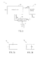
- FIG. 2 is a block diagram of a keyless entry system of a preferred embodiment of the invention.
- FIGs. 3A and 3B are schematic diagrams showing equivalent circuits of the resonant unit
- FIG. 4 is another block diagram of the keyless entry system of the preferred embodiment of the invention.
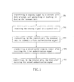
- FIG. 5 is a flow chart of a control method of the keyless entry system of the preferred embodiment of the invention.
- FIG. 2 is a block diagram of a keyless entry system 2 of a preferred embodiment of the invention.
- the keyless entry system 2 includes a resonant unit 21, a control unit 22 and a portable device 23.
- the portable device 23 is a portable object for the user O (a car-owner or a house-owner for example), and can be a key, a remote controller and so on.
- the keyless entry system 2 is suitable for the control of a car door, a house door or the access to any device. In the embodiment, the keyless entry system 2 is applied to the control of a car door for example.
- the resonant unit 21 is disposed to at least one door.
- the resonant unit 21 is disposed at the door handle of a car, so that the keyless entry system 2 can control to open the car door.
- the resonant unit 21 can generate a sensing signal SS when sensing a user O approaching or touching the door.
- the sensing signal SS is received by the control unit 22.
- FIGs. 3A and 3B are schematic diagrams showing different equivalent circuits of the resonant unit 21.
- the resonant unit 21 can be a dielectric resonator (DR), and the equivalent circuit thereof includes an inductor L and a capacitor C connected in series or in parallel.
- DR dielectric resonator
- the aspects shown in FIGs. 3A and 3B are just instanced, and the circuit of the resonant unit 21 can be adjusted for fitting the practical requirement.
- the control unit 22 includes an oscillating circuit 221 which is electrically connected to the resonant unit 21.
- the oscillating circuit 221 is a voltage controlled oscillator (VCO).
- VCO voltage controlled oscillator
- the resonant unit 21 makes the oscillating circuit 221 generate a natural resonant frequency f0.
- the natural resonant frequency f0 equals 1 / 2 ⁇ ⁇ ⁇ LC , wherein L represents the inductance value of the inductor L, and C represents the capacitance of the capacitor C.
- the resonant unit 21 transmits a sensing signal SS to the oscillating circuit 221, and the oscillating circuit 221 generates an oscillating frequency f1 according to the sensing signal SS.
- the control unit 22 further includes a control circuit 222 which determines whether a first authentication signal FAS is transmitted by the resonant unit 21 according to the oscillating frequency fl.
- the control circuit 222 compares the oscillating frequency f1 and natural resonant frequency f0. If the oscillating frequency f1 equals the natural resonant frequency f0, it means the user O doesn't approach or touch the resonant unit 21 and the user doesn't want to open the car door, so the control circuit 222 doesn't control the resonant unit 21 to transmit the first authentication signal FSA.
- the control circuit 222 controls the resonant unit 21 to transmit the first authentication signal FSA.
- the control circuit 222 controls the resonant 21 to transmit the first authentication signal FSA by controlling the oscillating circuit 221 to transmit a voltage signal VS to the resonant unit 21.
- the first authentication signal FSA is a low frequency signal. Because the resonant unit 21 is a dielectric resonator, it can act as a dielectric resonant antenna transmitting the first authentication signal FSA wirelessly, which means the resonant unit 21 is used as a transmission antenna.
- the portable device 23 can receive the first authentication signal FSA from the resonant unit 21, and transmit a second authentication signal SSA according to the first authentication signal FSA.
- the portable device 23 includes a first wireless receiving unit 23 and a wireless transmission unit 232.
- the first wireless receiving unit 231 receives the first authentication signal FSA.
- the wireless transmission unit 232 transmits the second authentication signal SSA according to the decoded signal.
- the second authentication signal SSA is a high frequency signal.
- the keyless entry system 2 is used to control whether the user 0 can enter the car door or the house door, so the user O must be near the car or the house when the first authentication signal FSA and the second authentication signal SSA are generated. Therefore, the signal transmission power of the whole system can be decreased.
- the control unit 22 further includes a second wireless receiving unit 223 which receives the second authentication signal SAS transmitted by the wireless transmission unit 232.
- the control circuit 222 determines whether to transmit a control signal CS for opening the door according to the second authentication signal SAS.
- the second wireless receiving unit 223 receives the second authentication signal SAS and transmits it to the control circuit 222. Then, the control circuit 222 decodes the second authentication signal SAS. If the second authentication signal SAS is the same as an effective signal stored or built in the control unit 22, the control circuit 222 transmits a control signal CS so that a lock actuator (not shown) is controlled to open the car door.
- the control circuit 222 will not transmit the control signal CS, and of course, the door is not opened.
- the control circuit 222 receives and decodes the second authentication signal SAS. If the user O is a real owner of the car or the house, the decoded signal will equal the code store or built in the control circuit 222, and then the control unit 22 can determine the second authentication signal SAS generated by the portable device 23 is an effective signal. Therefore, the control signal CS is transmitted to the lock actuator for opening the car door. On the contrary, the second authentication signal SAS is an ineffective signal.
- FIG. 5 is a flow chart of the control method of the keyless entry system 2.
- the control method of the keyless entry system 2 includes steps S01 to S05.
- the step S01 is to transmit a sensing signal SS by a resonant unit 22 when sensing a user O approaching or touching the door or the resonant unit 22.
- the resonant unit 21 is a dielectric resonator.
- the time constant of the resonant unit 21 changes due to the human induction.
- the resonant unit 21 generates the sensing signal SS, and the oscillating circuit 221 of the control unit 22 can, according to the sensing signal SS, generate an oscillating frequency f1 different from the natural resonant frequency f0.
- the step S02 is to receive the sensing signal SS by a control unit 22. Then, the step S03 is to control, by the control unit 22, the resonant unit 21 to transmit a first authentication signal FAS. If the oscillating frequency f1 is different from the natural resonant frequency f0, the control unit 22 controls the resonant unit 21 to transmit the first authentication signal FAS. If the oscillating frequency f1 equals the natural resonant frequency f0, the resonant unit 21 doesn't transmit the first authentication signal FAS.
- the step S04 is to transmit a second authentication signal SAS after receiving the first authentication signal FAS.
- the first authentication signal FAS is received by the first wireless receiving unit 231 of the portable device 23, and the second authentication signal SAS is transmitted by the wireless transmission unit 232 of the portable device 23 after receiving the first authentication signal FAS.
- the step S05 is to control, by the control unit 22, the door after receiving the second authentication signal SAS.
- the control circuit 222 transmits the control signal CS for opening the car door. Otherwise, if the second authentication signal SAS is different from the effective signal, the control circuit 222 doesn't transmit the control signal CS so that the door is not opened.
- a resonant unit transmits the first authentication signal when sensing a user approaching or touching the door or the resonant unit.
- a portable device transmits the second authentication signal
- a control unit controls the door according to the second authentication signal.
- the keyless entry system of the invention can sense whether a user approaches or touches without using a trigger device, and can transmit the identification signal without using an additional transmission antenna.
- the resonant unit of the invention replaces the trigger device and the transmission antenna, the control procedure of the keyless entry system is simplified. Therefore, the keyless entry system and the control method thereof of the invention have advantages of cost down and simple procedure.
Landscapes
- Engineering & Computer Science (AREA)
- Computer Networks & Wireless Communication (AREA)
- Physics & Mathematics (AREA)
- General Physics & Mathematics (AREA)
- Lock And Its Accessories (AREA)
Abstract
A keyless entry system comprises a resonant unit, a control unit and a portable device. The resonant unit is disposed to at least one door and generates a sensing signal when sensing a user approaching or touching the door. The control unit receives the sensing signal and controls the resonant unit to transmit a first authentication signal. The portable device receives the first authentication signal and transmits a second authentication signal according to the first authentication signal. The control unit receives the second authentication signal and controls the door according to the second authentication signal.
Description
- The invention relates to an entry system and a control method thereof and, in particular, to a keyless entry system and a control method thereof.
- In recent years, the adoption of keyless entry system for controlling the car door or the house door is more and more widespread.
- As shown in FIG. l, a conventional
keyless entry system 1 for cars includes atrigger device 11, acontrol device 12, aportable device 13 and alock actuator 14. Thecontrol device 12 includes acontrol circuit 121, atransmission circuit 122, atransmission antenna 123, areceiving antenna 124 and areceiving circuit 125. - When a user O approaches or touches the
trigger device 11, it generates a trigger signal TS to start an identification procedure. When thecontrol circuit 121 receives the trigger signal TS, an identification signal AS is transmitted by thetransmission circuit 122 and thetransmission antenna 123 through the control of thecontrol circuit 121. Then, the portable device 15 (e.g. a car key carried by the user O) receives and decodes the identification signal AS. If the identification signal AS is identified as correct, the portable device 15 will transmit a recognition signal MS to thecontrol device 12 by a high-frequency antenna of the portable device 15. The recognition signal MS is received by thereceiving antennal 124 and thereceiving circuit 125. When thecontrol circuit 121 decodes and determines the recognition signal MS is correct, thecontrol circuit 121 will control thelock actuator 14 to transmit an open signal OS for opening the car door. By the keyless entry system l, the user can open the car door without using a physical car key. - At present, a contact-type sensor or a photo sensor is used as the
trigger device 11 to sense whether the user O approaches or touches thetrigger device 11; hence, the procedure of determining whether the trigger of thetrigger device 11 occurs or not is more complicated. Besides, in the prior art, thecontrol device 12 needs thetransmission antenna 123 for transmitting the identification signal AS, so the cost of thekeyless entry system 1 is higher and the control procedure thereof is complicated. - Therefore, it is an important subject to provide a keyless entry system and a control method thereof that can decrease the cost and simplify the control procedure.
- In view of the foregoing subject, an object of the invention is to provide a keyless entry system and a control method thereof that can decrease the cost and simplify the control procedure.
- To achieve the above objective, the present invention discloses a keyless entry system which comprises a resonant unit, a control unit and a portable device. The resonant unit is disposed to at least one door and generates a sensing signal when sensing a user approaching or touching the door. The control unit receives the sensing signal and controls the resonant unit to transmit a first authentication signal. The portable device receives the first authentication signal and transmits a second authentication signal according to the first authentication signal. The control unit receives the second authentication signal and controls the door according to the second authentication signal.
- In one embodiment, the resonant unit is a resonator. The resonant unit comprises at least an inductor and at least a capacitor connected in series or in parallel.
- In one embodiment, the control unit comprises an oscillating circuit which is electrically connected with the resonant unit and receives the sensing signal for generating an oscillating frequency. The control unit further comprises a control circuit which determines whether the resonant unit transmits the first authentication signal according to the oscillating frequency. The control circuit controls the oscillating circuit to generate a voltage signal, so that the resonant unit transmits the first authentication signal. The control unit further comprises a second wireless receiving unit for receiving the second authentication signal. The control circuit determines whether to transmit a control signal for opening the door according to the second authentication signal.
- In one embodiment, the portable device comprises a first wireless receiving unit for receiving the first authentication signal, and a wireless transmission unit for transmitting the second authentication signal.
- To achieve the above objective, the present invention discloses a control method of a keyless entry system for controlling to open a door and comprises steps of: transmitting a sensing signal by a resonant unit when sensing a user approaching or touching the door or the resonant unit; receiving the sensing signal by a control unit; controlling, by the control unit, the resonant unit to transmit a first authentication signal; transmitting a second authentication signal after receiving the first authentication signal; and controlling, by the control unit, the door after receiving the second authentication signal. The resonant unit is a resonator.
- In one embodiment, the control method further comprises: generating an oscillating frequency by an oscillating circuit according to the sensing signal.
- In one embodiment, the control method further comprises: transmitting the first authentication signal if the oscillating frequency is different from a natural resonant frequency; and not transmitting the first authentication signal if the oscillating frequency equals the natural resonant frequency.
- In one embodiment, the control method further comprises: receiving the first authentication signal by a portable device; and transmitting the second authentication signal by the portable device.
- In one embodiment, the control method further comprises: opening the door if the second authentication signal is the same as an effective signal; and not opening the door if the second authentication signal is different from the effective signal.
- As mentioned above, in the keyless entry system and the control method thereof of the invention, a resonant unit transmits the first authentication signal when sensing a user approaching or touching the door or the resonant unit. According to the first authentication signal, a portable device transmits the second authentication signal, and a control unit controls the door according to the second authentication signal. Compared with the prior art, the keyless entry system of the invention can sense whether a user approaches or touches without using a trigger device, and can transmit the identification signal without using an additional transmission antenna. Besides, because the resonant unit of the invention replaces the trigger device and the transmission antenna, the control procedure of the keyless entry system is simplified. Therefore, the keyless entry system and the control method thereof of the invention have advantages of cost down and simple procedure.
- The invention will become more fully understood from the detailed description and accompanying drawings, which are given for illustration only, and thus are not limitative of the present invention, and wherein:
-
FIG. 1 is a block diagram of a conventional keyless entry system for cars; -
FIG. 2 is a block diagram of a keyless entry system of a preferred embodiment of the invention; -
FIGs. 3A and 3B are schematic diagrams showing equivalent circuits of the resonant unit; -
FIG. 4 is another block diagram of the keyless entry system of the preferred embodiment of the invention; and -
FIG. 5 is a flow chart of a control method of the keyless entry system of the preferred embodiment of the invention. - The present invention will be apparent from the following detailed description, which proceeds with reference to the accompanying drawings, wherein the same references relate to the same elements.
-
FIG. 2 is a block diagram of akeyless entry system 2 of a preferred embodiment of the invention. - The
keyless entry system 2 includes aresonant unit 21, acontrol unit 22 and aportable device 23. Theportable device 23 is a portable object for the user O (a car-owner or a house-owner for example), and can be a key, a remote controller and so on. Thekeyless entry system 2 is suitable for the control of a car door, a house door or the access to any device. In the embodiment, thekeyless entry system 2 is applied to the control of a car door for example. - The
resonant unit 21 is disposed to at least one door. In this case, theresonant unit 21 is disposed at the door handle of a car, so that thekeyless entry system 2 can control to open the car door. Theresonant unit 21 can generate a sensing signal SS when sensing a user O approaching or touching the door. The sensing signal SS is received by thecontrol unit 22. -
FIGs. 3A and 3B are schematic diagrams showing different equivalent circuits of theresonant unit 21. Theresonant unit 21 can be a dielectric resonator (DR), and the equivalent circuit thereof includes an inductor L and a capacitor C connected in series or in parallel. To be noted, the aspects shown inFIGs. 3A and 3B are just instanced, and the circuit of theresonant unit 21 can be adjusted for fitting the practical requirement. - As shown in
FIGs. 3A, 3B and4 , thecontrol unit 22 includes anoscillating circuit 221 which is electrically connected to theresonant unit 21. Herein, theoscillating circuit 221 is a voltage controlled oscillator (VCO). When the user O doesn't approach or touch theresonant unit 21, theresonant unit 21 makes theoscillating circuit 221 generate a natural resonant frequency f0. The natural resonant frequency f0 equals
resonant unit 21, the inductance value and capacitance of theresonant unit 21 will change as well as the time constant because of the human induction. Accordingly, theresonant unit 21 transmits a sensing signal SS to theoscillating circuit 221, and theoscillating circuit 221 generates an oscillating frequency f1 according to the sensing signal SS. - The
control unit 22 further includes acontrol circuit 222 which determines whether a first authentication signal FAS is transmitted by theresonant unit 21 according to the oscillating frequency fl. Thecontrol circuit 222 compares the oscillating frequency f1 and natural resonant frequency f0. If the oscillating frequency f1 equals the natural resonant frequency f0, it means the user O doesn't approach or touch theresonant unit 21 and the user doesn't want to open the car door, so thecontrol circuit 222 doesn't control theresonant unit 21 to transmit the first authentication signal FSA. Otherwise, if the oscillating frequency f1 is different from the natural resonant frequency f0, it means the user O approaches or touches theresonant unit 21 and also the user wants to open the car door, so thecontrol circuit 222 controls theresonant unit 21 to transmit the first authentication signal FSA. In the embodiment, thecontrol circuit 222 controls the resonant 21 to transmit the first authentication signal FSA by controlling theoscillating circuit 221 to transmit a voltage signal VS to theresonant unit 21. Herein, the first authentication signal FSA is a low frequency signal. Because theresonant unit 21 is a dielectric resonator, it can act as a dielectric resonant antenna transmitting the first authentication signal FSA wirelessly, which means theresonant unit 21 is used as a transmission antenna. - The
portable device 23 can receive the first authentication signal FSA from theresonant unit 21, and transmit a second authentication signal SSA according to the first authentication signal FSA. Theportable device 23 includes a firstwireless receiving unit 23 and awireless transmission unit 232. The firstwireless receiving unit 231 receives the first authentication signal FSA. After theportable device 23 decodes the first authentication signal FSA, thewireless transmission unit 232 transmits the second authentication signal SSA according to the decoded signal. Herein, the second authentication signal SSA is a high frequency signal. To be noted, thekeyless entry system 2 is used to control whether the user 0 can enter the car door or the house door, so the user O must be near the car or the house when the first authentication signal FSA and the second authentication signal SSA are generated. Therefore, the signal transmission power of the whole system can be decreased. - The
control unit 22 further includes a secondwireless receiving unit 223 which receives the second authentication signal SAS transmitted by thewireless transmission unit 232. Thecontrol circuit 222 determines whether to transmit a control signal CS for opening the door according to the second authentication signal SAS. The secondwireless receiving unit 223 receives the second authentication signal SAS and transmits it to thecontrol circuit 222. Then, thecontrol circuit 222 decodes the second authentication signal SAS. If the second authentication signal SAS is the same as an effective signal stored or built in thecontrol unit 22, thecontrol circuit 222 transmits a control signal CS so that a lock actuator (not shown) is controlled to open the car door. Otherwise, if the second authentication signal SAS is not the same as the effective signal, it means the second authentication signal SAS is an ineffective signal and the user O approaching or touching the door is not a real owner of the car or the house. Therefore, thecontrol circuit 222 will not transmit the control signal CS, and of course, the door is not opened. - In detail, the definition of the effective signal is as below. The
control circuit 222 receives and decodes the second authentication signal SAS. If the user O is a real owner of the car or the house, the decoded signal will equal the code store or built in thecontrol circuit 222, and then thecontrol unit 22 can determine the second authentication signal SAS generated by theportable device 23 is an effective signal. Therefore, the control signal CS is transmitted to the lock actuator for opening the car door. On the contrary, the second authentication signal SAS is an ineffective signal. - As shown in
FIGs. 4 and5 , a control method of thekeyless entry system 2 is illustrated as below.FIG. 5 is a flow chart of the control method of thekeyless entry system 2. The control method of thekeyless entry system 2 includes steps S01 to S05. - The step S01 is to transmit a sensing signal SS by a
resonant unit 22 when sensing a user O approaching or touching the door or theresonant unit 22. Theresonant unit 21 is a dielectric resonator. When the user O approaches or touches the door or theresonant unit 22, the time constant of theresonant unit 21 changes due to the human induction. Then, theresonant unit 21 generates the sensing signal SS, and theoscillating circuit 221 of thecontrol unit 22 can, according to the sensing signal SS, generate an oscillating frequency f1 different from the natural resonant frequency f0. - The step S02 is to receive the sensing signal SS by a
control unit 22. Then, the step S03 is to control, by thecontrol unit 22, theresonant unit 21 to transmit a first authentication signal FAS. If the oscillating frequency f1 is different from the natural resonant frequency f0, thecontrol unit 22 controls theresonant unit 21 to transmit the first authentication signal FAS. If the oscillating frequency f1 equals the natural resonant frequency f0, theresonant unit 21 doesn't transmit the first authentication signal FAS. - The step S04 is to transmit a second authentication signal SAS after receiving the first authentication signal FAS. Herein, the first authentication signal FAS is received by the first
wireless receiving unit 231 of theportable device 23, and the second authentication signal SAS is transmitted by thewireless transmission unit 232 of theportable device 23 after receiving the first authentication signal FAS. - The step S05 is to control, by the
control unit 22, the door after receiving the second authentication signal SAS. Herein, if the second authentication signal SAS is the same as an effective signal built in thecontrol circuit 222, thecontrol circuit 222 transmits the control signal CS for opening the car door. Otherwise, if the second authentication signal SAS is different from the effective signal, thecontrol circuit 222 doesn't transmit the control signal CS so that the door is not opened. - The further technical features of the
keyless entry system 2 are illustrated clearly as the above embodiments, so the detailed descriptions thereof are omitted. - In summary, in the keyless entry system and the control method thereof of the invention, a resonant unit transmits the first authentication signal when sensing a user approaching or touching the door or the resonant unit. According to the first authentication signal, a portable device transmits the second authentication signal, and a control unit controls the door according to the second authentication signal. Compared with the prior art, the keyless entry system of the invention can sense whether a user approaches or touches without using a trigger device, and can transmit the identification signal without using an additional transmission antenna. Besides, because the resonant unit of the invention replaces the trigger device and the transmission antenna, the control procedure of the keyless entry system is simplified. Therefore, the keyless entry system and the control method thereof of the invention have advantages of cost down and simple procedure.
- Although the invention has been described with reference to specific embodiments, this description is not meant to be construed in a limiting sense. Various modifications of the disclosed embodiments, as well as alternative embodiments, will be apparent to persons skilled in the art. It is, therefore, contemplated that the appended claims will cover all modifications that fall within the true scope of the invention.
Claims (15)
- A keyless entry system, comprising:a resonant unit (21) disposed to at least one door and generating a sensing signal (SS) when sensing a user approaching or touching the door;a control unit (22) receiving the sensing signal and controlling the resonant unit to transmit a first authentication signal (FSA); anda portable device (23) receiving the first authentication signal and transmitting a second authentication signal (SSA) according to the first authentication signal, wherein the control unit receives the second authentication signal and controls the door according to the second authentication signal.
- The keyless entry system as recited in claim 1, wherein the resonant unit is a resonator.
- The keyless entry system as recited in claim 1 or 2, wherein the resonant unit comprises at least an inductor and at least a capacitor connected in series or in parallel.
- The keyless entry system as recited in any of the preceding claims, wherein the control unit comprises an oscillating circuit which is electrically connected with the resonant unit and receives the sensing signal for generating an oscillating frequency.
- The keyless entry system as recited in claim 4, wherein the control unit further comprises a control circuit which determines whether the resonant unit transmits the first authentication signal according to the oscillating frequency.
- The keyless entry system as recited in claim 5, wherein the control circuit controls the oscillating circuit to generate a voltage signal, so that the resonant unit transmits the first authentication signal.
- The keyless entry system as recited in any of the preceding claims, wherein the portable device comprises a first wireless receiving unit (231) for receiving the first authentication signal (FSA), and a wireless transmission unit (232) for transmitting the second authentication signal (SSA).
- The keyless entry system as recited in transmission unit, wherein the control unit further includes a second wireless receiving unit (223) for receiving the second authentication signal.
- The keyless entry system as recited in claim 5, wherein the control circuit determines whether to transmit a control signal for opening the door according to the second authentication signal.
- A control method of a keyless entry system for controlling to open a door, comprising steps of:transmitting a sensing signal by a resonant unit when sensing a user approaching or touching the door or the resonant unit;receiving the sensing signal by a control unit;controlling, by the control unit, the resonant unit to transmit a first authentication signal;transmitting a second authentication signal after receiving the first authentication signal; andcontrolling, by the control unit, the door after receiving the second authentication signal.
- The control method as recited in claim 10, further comprising:generating an oscillating frequency by an oscillating circuit according to the sensing signal.
- The control method as recited in claim 11 or 12, further comprising:transmitting the first authentication signal if the oscillating frequency is different from a natural resonant frequency; andnot transmitting the first authentication signal if the oscillating frequency equals the natural resonant frequency.
- The control method as recited in any of claims 10 to 12, further comprising:receiving the first authentication signal by a portable device; andtransmitting the second authentication signal by the portable device.
- The control method as recited in any of claims 10 to 13, further comprising:opening the door if the second authentication signal is the same as an effective signal; andnot opening the door if the second authentication signal is different from the effective signal.
- The control method as recited in any of claims 10 to 14, wherein the resonant unit is a resonator.
Applications Claiming Priority (1)
| Application Number | Priority Date | Filing Date | Title |
|---|---|---|---|
| TW100141535A TW201319371A (en) | 2011-11-15 | 2011-11-15 | Keyless entry system and control method thereof |
Publications (1)
| Publication Number | Publication Date |
|---|---|
| EP2595120A2 true EP2595120A2 (en) | 2013-05-22 |
Family
ID=46026670
Family Applications (1)
| Application Number | Title | Priority Date | Filing Date |
|---|---|---|---|
| EP12164820.8A Withdrawn EP2595120A2 (en) | 2011-11-15 | 2012-04-19 | Keyless entry system and control method thereof |
Country Status (3)
| Country | Link |
|---|---|
| US (1) | US20130120111A1 (en) |
| EP (1) | EP2595120A2 (en) |
| TW (1) | TW201319371A (en) |
Cited By (1)
| Publication number | Priority date | Publication date | Assignee | Title |
|---|---|---|---|---|
| WO2018150106A1 (en) * | 2017-02-17 | 2018-08-23 | Continental Automotive France | Method for detecting a user's intention to lock or unlock a motor vehicle door and associated device |
-
2011
- 2011-11-15 TW TW100141535A patent/TW201319371A/en unknown
-
2012
- 2012-04-16 US US13/447,794 patent/US20130120111A1/en not_active Abandoned
- 2012-04-19 EP EP12164820.8A patent/EP2595120A2/en not_active Withdrawn
Non-Patent Citations (1)
| Title |
|---|
| None |
Cited By (4)
| Publication number | Priority date | Publication date | Assignee | Title |
|---|---|---|---|---|
| WO2018150106A1 (en) * | 2017-02-17 | 2018-08-23 | Continental Automotive France | Method for detecting a user's intention to lock or unlock a motor vehicle door and associated device |
| CN110268632A (en) * | 2017-02-17 | 2019-09-20 | 法国大陆汽车公司 | Method and associated apparatus for detecting a user's intent to lock or unlock a motor vehicle door |
| US11078692B2 (en) | 2017-02-17 | 2021-08-03 | Continental Automotive France | Method for detecting a user's intention to lock or unlock a motor vehicle door and associated device |
| CN110268632B (en) * | 2017-02-17 | 2023-07-07 | 纬湃科技有限责任公司 | Method for detecting the intention of a user to lock or unlock a door of a motor vehicle and related device |
Also Published As
| Publication number | Publication date |
|---|---|
| US20130120111A1 (en) | 2013-05-16 |
| TW201319371A (en) | 2013-05-16 |
Similar Documents
| Publication | Publication Date | Title |
|---|---|---|
| AU2017229437B2 (en) | Near field communication tag | |
| US8437696B2 (en) | Low power near-field communication devices | |
| US20170282858A1 (en) | Keyless Entry Systems | |
| US20150314756A1 (en) | Passive access system for a motor vehicle and corresponding method | |
| US20090261945A1 (en) | Passive entry system and method for performing function thereof | |
| JP4196172B2 (en) | Detection device and lock control device | |
| CN106304311B (en) | It leaves and extends the method for tele-control system communication range during lockking control function | |
| JP2013048517A (en) | In-vehicle portable terminal charging device | |
| CN110268632A (en) | Method and associated apparatus for detecting a user's intent to lock or unlock a motor vehicle door | |
| KR20190081118A (en) | Apparatus and method for controlling vehicles | |
| US7592895B2 (en) | System and method for remotely controlling a function | |
| CN103842218B (en) | Utilize the RFID reader triggering method and apparatus for activating the process of the device of the car door that comes in and goes out for locking locking/unlocking motor vehicles | |
| JP4793944B2 (en) | Detection device and lock control device | |
| CN115042743A (en) | Vehicle control device and vehicle control method | |
| US20190130673A1 (en) | Garage door opener with touch sensor authentication | |
| US20170140591A1 (en) | On-vehicle apparatus, vehicle locking/unlocking system, and method of controlling on-vehicle apparatus | |
| US20130120111A1 (en) | Keyless entry system and control method thereof | |
| JP5365845B2 (en) | Vehicle door control system and vehicle door control method | |
| JP5548075B2 (en) | Communication output setting device | |
| KR20200004170A (en) | Ring type remote controller and method for operating thereof | |
| JP5416065B2 (en) | Communication mode setting device | |
| JP2005113608A (en) | Remote locking / unlocking control device for vehicle | |
| JP2015202767A (en) | Keyless system and portable device | |
| KR20080014064A (en) | Use of electronic communication systems, base stations, transponder stations, communication methods and electronic communication systems | |
| JP2004040803A (en) | Method for controlling access to prescribed space via personal hand baggage, and hand baggage for carrying out the same method |
Legal Events
| Date | Code | Title | Description |
|---|---|---|---|
| PUAI | Public reference made under article 153(3) epc to a published international application that has entered the european phase |
Free format text: ORIGINAL CODE: 0009012 |
|
| AK | Designated contracting states |
Kind code of ref document: A2 Designated state(s): AL AT BE BG CH CY CZ DE DK EE ES FI FR GB GR HR HU IE IS IT LI LT LU LV MC MK MT NL NO PL PT RO RS SE SI SK SM TR |
|
| AX | Request for extension of the european patent |
Extension state: BA ME |
|
| STAA | Information on the status of an ep patent application or granted ep patent |
Free format text: STATUS: THE APPLICATION HAS BEEN WITHDRAWN |
|
| 18W | Application withdrawn |
Effective date: 20140305 |