EP2594984A2 - Mehrstufiger Biegungskolben - Google Patents
Mehrstufiger Biegungskolben Download PDFInfo
- Publication number
- EP2594984A2 EP2594984A2 EP12185228.9A EP12185228A EP2594984A2 EP 2594984 A2 EP2594984 A2 EP 2594984A2 EP 12185228 A EP12185228 A EP 12185228A EP 2594984 A2 EP2594984 A2 EP 2594984A2
- Authority
- EP
- European Patent Office
- Prior art keywords
- support member
- stage
- coupler
- flexure
- axis
- Prior art date
- Legal status (The legal status is an assumption and is not a legal conclusion. Google has not performed a legal analysis and makes no representation as to the accuracy of the status listed.)
- Granted
Links
Images



Classifications
-
- F—MECHANICAL ENGINEERING; LIGHTING; HEATING; WEAPONS; BLASTING
- F16—ENGINEERING ELEMENTS AND UNITS; GENERAL MEASURES FOR PRODUCING AND MAINTAINING EFFECTIVE FUNCTIONING OF MACHINES OR INSTALLATIONS; THERMAL INSULATION IN GENERAL
- F16C—SHAFTS; FLEXIBLE SHAFTS; ELEMENTS OR CRANKSHAFT MECHANISMS; ROTARY BODIES OTHER THAN GEARING ELEMENTS; BEARINGS
- F16C11/00—Pivots; Pivotal connections
- F16C11/04—Pivotal connections
- F16C11/12—Pivotal connections incorporating flexible connections, e.g. leaf springs
-
- F—MECHANICAL ENGINEERING; LIGHTING; HEATING; WEAPONS; BLASTING
- F16—ENGINEERING ELEMENTS AND UNITS; GENERAL MEASURES FOR PRODUCING AND MAINTAINING EFFECTIVE FUNCTIONING OF MACHINES OR INSTALLATIONS; THERMAL INSULATION IN GENERAL
- F16D—COUPLINGS FOR TRANSMITTING ROTATION; CLUTCHES; BRAKES
- F16D3/00—Yielding couplings, i.e. with means permitting movement between the connected parts during the drive
- F16D3/50—Yielding couplings, i.e. with means permitting movement between the connected parts during the drive with the coupling parts connected by one or more intermediate members
- F16D3/56—Yielding couplings, i.e. with means permitting movement between the connected parts during the drive with the coupling parts connected by one or more intermediate members comprising elastic metal lamellae, elastic rods, or the like, e.g. arranged radially or parallel to the axis, the members being shear-loaded collectively by the total load
-
- Y—GENERAL TAGGING OF NEW TECHNOLOGICAL DEVELOPMENTS; GENERAL TAGGING OF CROSS-SECTIONAL TECHNOLOGIES SPANNING OVER SEVERAL SECTIONS OF THE IPC; TECHNICAL SUBJECTS COVERED BY FORMER USPC CROSS-REFERENCE ART COLLECTIONS [XRACs] AND DIGESTS
- Y10—TECHNICAL SUBJECTS COVERED BY FORMER USPC
- Y10T—TECHNICAL SUBJECTS COVERED BY FORMER US CLASSIFICATION
- Y10T29/00—Metal working
- Y10T29/43—Electric condenser making
- Y10T29/435—Solid dielectric type
-
- Y—GENERAL TAGGING OF NEW TECHNOLOGICAL DEVELOPMENTS; GENERAL TAGGING OF CROSS-SECTIONAL TECHNOLOGIES SPANNING OVER SEVERAL SECTIONS OF THE IPC; TECHNICAL SUBJECTS COVERED BY FORMER USPC CROSS-REFERENCE ART COLLECTIONS [XRACs] AND DIGESTS
- Y10—TECHNICAL SUBJECTS COVERED BY FORMER USPC
- Y10T—TECHNICAL SUBJECTS COVERED BY FORMER US CLASSIFICATION
- Y10T29/00—Metal working
- Y10T29/49—Method of mechanical manufacture
- Y10T29/49826—Assembling or joining
-
- Y—GENERAL TAGGING OF NEW TECHNOLOGICAL DEVELOPMENTS; GENERAL TAGGING OF CROSS-SECTIONAL TECHNOLOGIES SPANNING OVER SEVERAL SECTIONS OF THE IPC; TECHNICAL SUBJECTS COVERED BY FORMER USPC CROSS-REFERENCE ART COLLECTIONS [XRACs] AND DIGESTS
- Y10—TECHNICAL SUBJECTS COVERED BY FORMER USPC
- Y10T—TECHNICAL SUBJECTS COVERED BY FORMER US CLASSIFICATION
- Y10T403/00—Joints and connections
- Y10T403/32—Articulated members
- Y10T403/32606—Pivoted
-
- Y—GENERAL TAGGING OF NEW TECHNOLOGICAL DEVELOPMENTS; GENERAL TAGGING OF CROSS-SECTIONAL TECHNOLOGIES SPANNING OVER SEVERAL SECTIONS OF THE IPC; TECHNICAL SUBJECTS COVERED BY FORMER USPC CROSS-REFERENCE ART COLLECTIONS [XRACs] AND DIGESTS
- Y10—TECHNICAL SUBJECTS COVERED BY FORMER USPC
- Y10T—TECHNICAL SUBJECTS COVERED BY FORMER US CLASSIFICATION
- Y10T403/00—Joints and connections
- Y10T403/54—Flexible member is joint component
Definitions
- Flexural pivots are devices that permit mechanical members to pivot about a common axis relative to each other through a limited angle range. Because angular motion is accomplished through flexing of elastic flexural elements, rather than contact surface displacement, flexural pivots operate without friction and thus without a need for lubrication. Flexural pivots can therefore be a substitute for bearings in applications where friction and/or the need for lubrication are concerns.
- the second support member to be rotatable about an axis relative to the first support member; the coupler to be rotatable about the axis relative to the first support member and the second support member; and the plurality of flexures, each flexure having first and second flexible members arranged substantially perpendicular to one another and offset from one another along the axis, wherein a first flexure of the plurality of flexures is coupled between the first support member and the coupler to form a first stage and to provide for relative rotational movement between the first support member and the coupler about the axis, wherein a second flexure of the plurality of flexures is coupled between the second support member and the coupler to form a second stage and provide for relative rotational movement between the second support member and the coupler about the axis, and wherein relative rotational movement between the first support member and the second support member about the axis is a sum of the relative rotational movements of the first stage and the second stage.
- first stage may further comprise a third flexure of the plurality of flexures coupled between the first support member and the coupler to improve off-axis bending stiffness of the first stage.
- the second stage may further comprise a fourth flexure of the plurality of flexures coupled between the second support member and the coupler to improve off-axis bending stiffness of the second stage.
- the second flexure can be disposed between the first flexure and the third flexure along the axis to intersperse components of the first stage and the second stage and increase off-axis bending stiffness of the flexural pivot.
- the first flexure can be disposed between the second flexure and the fourth flexure along the axis to intermingle components of the first stage and the second stage and increase off-axis bending stiffness of the flexural pivot.
- Each of the first and second flexible members can have a support end and a coupler end, the support ends of the flexible members of the first flexure being coupled to the first support member, the support ends of the flexible members of the second flexure being coupled to the second support member, and the coupler ends of each of the flexible members being coupled to the coupler.
- It is an aspect of certain embodiments of the present invention to provide a method for configuring a multi-stage flexural pivot comprising; obtaining a first support member, a second support member, a coupler rotatable about an axis relative to the first support member and the second support member, and a plurality of flexures, each flexure having first and second flexible members arranged substantially perpendicular to one another and laterally offset from one another, and each of the first and second flexible members having a support end and a coupler end; disposing a first flexure of the plurality of flexures between the first support member and the coupler to form a first stage and to provide for relative rotational movement between the first support member and the coupler about the axis; and disposing a second flexure of the plurality of flexures between the second support member and the coupler to form a second stage and provide for relative rotational movement between the second support member and the coupler about the axis, wherein relative rotational movement between the first support member and the second support member
- FIG. 1A is an example illustration of a multi-stage flexural pivot in accordance with an embodiment of the present invention.
- FIG. 1B is an end view of the multi-stage flexural pivot of FIG. 1A .
- FIG. 1C is an exploded view of the multi-stage flexural pivot of FIG. 1A .
- FIG. 2 is load path diagram of the multi-stage flexural pivot of FIG. 1A .
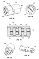
- FIG. 3A is an example illustration of a multi-stage flexural pivot in accordance with another embodiment of the present invention.
- FIG. 3B is an end view of the multi-stage flexural pivot of FIG. 3A .
- FIG. 3C is a section view of the multi-stage flexural pivot of FIG. 3A .
- FIG. 3D is an example illustration of a support member of the multi-stage flexural pivot of FIG. 3A .
- FIG. 3E is an example illustration of a coupler of the multi-stage flexural pivot of FIG. 3A .
- FIG. 4A is an example illustration of a multi-stage flexural pivot in accordance with yet another embodiment of the present invention.
- FIG. 4B is an exploded view of the multi-stage flexural pivot of FIG. 4A .
- FIG. 5A is an example illustration of a multi-stage flexural pivot in accordance with still another embodiment of the present invention.
- FIG. 5B is an exploded view of the multi-stage flexural pivot of FIG. 5A .
- FIG. 6 is an example illustration of a flexure of a multi-stage flexural pivot in accordance with an embodiment of the present invention.
- the term “substantially” refers to the complete or nearly complete extent or degree of an action, characteristic, property, state, structure, item, or result.
- an object that is “substantially” enclosed would mean that the object is either completely enclosed or nearly completely enclosed.
- the exact allowable degree of deviation from absolute completeness may in some cases depend on the specific context. However, generally speaking the nearness of completion will be so as to have the same overall result as if absolute and total completion were obtained.
- the use of “substantially” is equally applicable when used in a negative connotation to refer to the complete or near complete lack of an action, characteristic, property, state, structure, item, or result.
- flexural pivots have many advantages, the limited range of angular motion available with flexural pivots, however, can preclude using flexural pivots in some applications. Additionally, the axis of rotation of flexural pivots can shift when moved through the range of angular motion, which can be detrimental in precision applications. Moreover, bending stiffness of flexural pivots can be a concern due to the inherent flexibility of the elastic flexural elements. Thus, potential applications for flexural pivots can increase by increasing the range of angular motion, minimizing the shift of the axis of rotation, and increasing bending stiffness.
- a multi-stage flexural pivot that increases the range of angular motion over typical flexural pivots and minimizes the shift of the axis of rotation as the flexural pivot operates.
- bending stiffness is increased over typical flexural pivots.
- the flexural pivot includes a first support member, a second support member, a coupler, and a plurality of flexures, each flexure having first and second flexible members arranged substantially perpendicular to one another and laterally offset from one another.
- a first flexure of the plurality of flexures is coupled between the first support member and the coupler to form a first stage and provide for relative rotational movement between the first support member and the coupler.
- a second flexure of the plurality of flexures is coupled between the second support member and the coupler to form a second stage and provide for relative rotational movement between the second support member and the coupler.
- Relative rotational movement between the first support member and the second support member is a sum of the relative rotational movements of the first stage and the second stage.
- the multi-stage flexural pivot 100 can comprise a first support member 110, a second support member 120, a coupler 130, and a plurality of flexures 140, 150.
- the second support member 120 can be rotatable, such as about an axis 102, relative to the first support member 110.
- the coupler 130 can be rotatable, such as about the axis 102, relative to the first support member 110 and the second support member 120.
- the first support member 110 and the second support member 120 can be rotatably coupled to one another via the coupler 130 and the flexures 140, 150.
- Each flexure can have first and second flexible members arranged substantially perpendicular to one another and offset from one another, such as along the axis 102.
- flexure 140 includes a pair of flexible members 141, 142 and flexure 150 includes a pair of flexible members 151, 152.
- a flexure can include two or more flexible members, with at least one of the flexible members being substantially perpendicular to at least one other flexible member within the flexure.
- Flexure 140 can be coupled between the first support member 110 and the coupler 130 to form a first stage of rotation and to provide for relative rotational movement between the first support member 110 and the coupler 130 about the axis 102.
- Flexure 150 can be coupled between the second support member 120 and the coupler 130 to form a second stage of rotation and provide for relative rotational movement between the second support member 120 and the coupler 130 about the axis 102.
- Relative rotational movement between the first support member 110 and the second support member 120 about the axis 102 is a sum of the relative rotational movements of the first stage and the second stage.
- Each of the flexible members can have a support end and a coupler end for coupling between the support members and the coupler.
- flexible member 140 can have a support end 143 and a coupler end 144.
- the support ends of the flexible members can couple to the support members 110, 120.
- the support end 143 of flexible member 140 is coupled to the first support member 110, in this case, at an inner surface 111 configured as a slot.
- the support end of a flexible member can be attached to a support member with a braze, weld, adhesive, crimp, fastener, interference fit, or any other suitable form of attachment for a flexible member and a support member.
- the coupler ends of the flexible members can be coupled to the coupler 130.
- the coupler end 144 of flexible member 141 is coupled to the coupler 130 at coupling location 131.
- the coupler 130 can comprise a radial opening 132 extending from an outer surface 134 of the coupler 130 (e.g., through a center of the coupler) to receive the coupler end 144 of flexible member 141 disposed within the radial opening 132.
- a coupler end of a flexible member can be attached to the coupler with a braze, weld, adhesive, crimp, fastener, interference fit, or any other suitable form of attachment for a flexible member and a coupler.
- the flexible members can comprise a blade configuration.
- the support members and the coupler can be configured to interface with the support end and the coupler end of the blade, respectively, to facilitate attachment with the blade.
- the support members and the coupler can be configured to couple with a flexible member such that the support member coupling location 116 and the coupler coupling location 136 define a circle 104 substantially centered about the axis 102.
- the shift of the axis of rotation during operation can be reduced.
- the two stage configuration of the multi-stage flexural pivot 100 can further reduce the shift of the axis of rotation.
- each stage produces some amount of shift of the axis of rotation.
- the stages are configured such that the shift due to operation of one stage is offset at least to some degree by the shift due to operation of the other stage. Thus, the total net shift of the axis of rotation can be minimized with the multi-stage flexural pivot 100.
- an outer surface of the coupler 130 can be at least partially cylindrical about the axis 102.
- a cylindrical configuration can facilitate rotational movement of the coupler 130 about the axis 102, particularly if the coupler 130 is disposed at least partially within the first support member 110 and/or the second support member 120. Locating the coupler in the center of the pivot flexure can result in a low rotating inertia, which can provide high bandwidth capabilities for applications such as servo-control mechanisms.
- an outer surface of the first support member 110 and/or the second support member 120 can be substantially cylindrical about the axis 102.
- a cylindrical outer surface configuration can facilitate coupling a support member with a base support.
- a base support may be configured to interface with a cartridge bearing having a cylindrical exterior surface.
- the cartridge bearing can be replaced with a multi-stage flexural pivot having a cylindrical outer surface.
- an outer surface of a support member can be of any suitable geometric configuration for interfacing with a base support and, in one aspect, can be integrated with a base support.
- FIG. 2 Shown in FIG. 2 is a schematic illustration of a load path of the multi-stage flexural pivot 100.
- the load path splits into parallel paths to the flexible members 141, 142 of the flexure 140.
- the load path then converges from the flexible members 141, 142 to the coupler 130.
- the load path splits into parallel paths to the flexible members 151, 152 of the flexure 150.
- the load path then converges from the flexible members 151, 152 to the second support member 120.
- the parallel load paths through the flexible members of both flexures 140, 150 converge at the coupler 130, such that the coupler 130 reacts to all loads through the multi-stage flexural pivot 100.
- This coupler configuration provides stiffness for the multi-stage flexural pivot 100 as it ties the flexures 140, 150 together.
- FIGs. 3A-3E An embodiment of a multi-stage flexural pivot 200 is illustrated in FIGs. 3A-3E .
- enhanced stiffness over the multi-stage flexural pivot 100 shown in FIGs. 1A-1C can be achieved.
- the multi-stage flexural pivot 200 can further comprise a third flexure coupled between the first support member 210 and the coupler 230 to improve off-axis bending stiffness of the first stage.
- a fourth flexure can be coupled between the second support member 220 and the coupler 230 to improve off-axis bending stiffness of the second stage.
- flexure 240 can be coupled between the first support member 210 and the coupler 230 and flexure 250 can be coupled between the second support member 220 and the coupler 230.
- a coupling having two flexures between a support member and the coupler can improve bending stiffness over a coupling having only a single flexure between a support member and the coupler.
- Flexure 260 can therefore be coupled between the first support member 210 and the coupler 230 to improve bending stiffness of the first stage.
- flexure 270 can be coupled between the second support member 220 and the coupler 230 to improve bending stiffness of the second stage.
- the flexure 250 can be disposed between flexure 240 and flexure 260 along the axis 202 to intersperse or intermingle components of the first stage and the second stage and increase off-axis bending stiffness of the flexural pivot 200.
- flexure 240 can be disposed between flexure 250 and flexure 270 along the axis to intersperse or intermingle components of the first stage and the second stage and increase off-axis bending stiffness of the flexural pivot 200.
- flexures of a single stage can be spaced apart from one another to make room for a flexure of another stage (such as flexure 250).
- This additional spacing to accommodate an intermingled flexure can improve stiffness over a lesser spacing between flexures of a given stage.
- intermingling of stages can reduce the overall length of the multi-stage flexural pivot 200, which can also have a positive effect on stiffness.
- incorporating an additional flexure in a given stage and intermingling flexures of different stages can improve or enhance the stiffness characteristics of a flexural pivot.
- the second support member 220 can be disposed at least partially within (i.e., overlap) the first support member 210 and/or the first support member 210 can be disposed at least partially within the second support member 220.
- This configuration can be implemented when intermingling flexures of different stages. For example, in order to dispose the first flexure 240 between the second flexure 250 and the fourth flexure 270, at least a portion 212 of the first support member 210 can be disposed within the second support member 220 to provide a coupling location for the flexure 240.
- the second support member 220 can be disposed within the first support member 210 to provide a coupling location for the flexure 250.
- the first support member 210 is shown in FIG. 3D .
- the second support member 220 can be configured to be substantially the same as, or identical to, the first support member 210.
- the coupler 230 is shown in FIG. 3E and illustrates a configuration to accommodate eight flexible members of the four flexures 240, 250, 260, 270 of the multi-stage flexural pivot 200.
- FIGs. 4A-4B An embodiment of a multi-stage flexural pivot 300 is illustrated in FIGs. 4A-4B .
- an additional coupler and support member can provide increased rotational movement range over the multi-stage flexural pivot 100 shown in FIGs. 1A-1C .
- the multi-stage flexural pivot 300 can further comprise a coupler 390 rotatable about an axis 302 relative to a first support member 310, a second support member 320, and a coupler 330.
- the multi-stage flexural pivot 300 can comprise a third support member 380 rotatable about the axis 302 relative to the first support member 310, the second support member 320, the coupler 330, and the coupler 390.
- the third support member 380 can be rotatably coupled to the second support member 320 via coupler 390 and flexures 360, 370.
- the additional coupler 390 and the third support member 380 provide two additional stages of rotation, which doubles the number of stages. This can increase the rotational movement range over the multi-stage flexural pivot 100, discussed above, by a factor of two.
- flexure 340 can be coupled between the first support member 310 and the coupler 330 to form a first stage and flexure 350 can be coupled between the second support member 320 and the coupler 330 to form a second stage.
- flexure 360 can be coupled between the second support member 320 and the coupler 390 to form a third stage and provide for relative rotational movement between the second support member 320 and the coupler 390 about the axis 302.
- flexure 370 can be coupled between the third support member 380 and the coupler 390 to form a fourth stage and provide for relative rotational movement between the third support member 380 and the coupler 390 about the axis 302.
- Relative rotational movement between the first support member 310 and the third support member 380 about the axis 302 is a sum of the relative rotational movements of the first stage, the second stage, the third stage, and the fourth stage.
- FIGs. 5A-5B An embodiment of a multi-stage flexural pivot 400 is illustrated in FIGs. 5A-5B .
- an additional support member relative to the multi-stage flexural pivot 100 shown in FIGs. 1A-1C , can provide a double-ended multi-stage flexural pivot 400.
- the multi-stage flexural pivot 400 can further comprise a third support member 480 rotatable about an axis 402 relative to a second support member 420 and a coupler 430.
- the first support member 410 and the third support member 480 are coupleable to one another to provide for substantially the same rotational movement relative to the second support member 420.
- flexure 440 can be coupled between the first support member 410 and the coupler 430 to form a first stage and flexures 450, 460 can be coupled between the second support member 420 and the coupler 430 to form a second stage.
- a flexure 470 can be coupled between the third support member 480 and the coupler 430 to provide for relative rotational movement between the third support member 480 and the coupler 430 about the axis 402.
- the first support member 410 and the third support member 480 can be constrained to move with one another, or in other words, constrained such that there is no relative rotational movement between them.
- the multi-stage flexural pivot 400 can function as a double-ended flexural pivot.
- the second support member 420 can be configured to support or couple with an object that is desired to be rotatable relative to both ends of the flexural pivot 400, which may be fixed in a base support.
- the second stage optionally includes two flexures 450, 460, that can provide increased bending stiffness over a single flexure per stage.
- FIG. 6 An embodiment of a flexure 540 that can be used in a multi-stage flexural pivot is illustrated in FIG. 6 .
- the example flexures illustrated include two flexible members per flexure.
- a flexure can include two or more flexible members.
- a flexure 540 having three flexible members 541, 542, 543 is shown in FIG. 6 .
- Flexible member 541 is arranged substantially perpendicular to, and laterally offset from, flexible member 542.
- the flexible members can be offset along axis 502.
- Flexible member 543 is arranged substantially parallel to, and laterally offset from, flexible member 541.
- flexible member 542 can be disposed between flexible members 541, 543.
- the spacing provided between flexible members 541, 543 in this arrangement can improve stiffness in one dimension.
- Flexible member 542 is wider than flexible members 541, 543 and thus provides improved stiffness in another dimension.
- Three flexible members thus configured and arranged can be utilized to improve bending stiffness of a coupling between a support member and a coupler.
- a method for configuring a multi-stage flexural pivot can comprise obtaining a first support member, a second support member, a coupler rotatable about an axis relative to the first support member and the second support member, and a plurality of flexures, each flexure having first and second flexible members arranged substantially perpendicular to one another and laterally offset from one another, and each of the first and second flexible members having a support end and a coupler end.
- the method further comprises disposing a first flexure of the plurality of flexures between the first support member and the coupler to form a first stage and to provide for relative rotational movement between the first support member and the coupler about the axis.
- the method can comprise disposing a second flexure of the plurality of flexures between the second support member and the coupler to form a second stage and provide for relative rotational movement between the second support member and the coupler about the axis, wherein relative rotational movement between the first support member and the second support member about the axis is a sum of the relative rotational movements of the first stage and the second stage.
- a method for facilitating rotation of an object can comprise configuring a multi-stage flexural pivot to comprise a first support member, a second support member rotatable about an axis relative to the first support member, a coupler rotatable about the axis relative to the first support member and the second support member, and a plurality of flexures, each flexure having first and second flexible members arranged substantially perpendicular to one another and offset from one another along the axis, and each of the first and second flexible members having a support end and a coupler end.
- a first flexure of the plurality of flexures is coupled between the first support member and the coupler to form a first stage and to provide for relative rotational movement between the first support member and the coupler about the axis.
- a second flexure of the plurality of flexures is coupled between the second support member and the coupler to form a second stage and provide for relative rotational movement between the second support member and the coupler about the axis.
- Relative rotational movement between the first support member and the second support member about the axis is a sum of the relative rotational movements of the first stage and the second stage.
- the method can comprise facilitating coupling of the multi-stage flexural pivot to an object to provide angular rotation of the object.
- a multi-stage flexural pivot comprising: a first support member and a second support member rotatably coupled to one another via a coupler and a plurality of flexures, each flexure having a pair of flexible members arranged substantially perpendicular to one another and laterally offset from one another, and each of the flexible members having a support end and a coupler end, wherein a first flexure of the plurality of flexures is coupled between the first support member and the coupler to form a first stage and provide for relative rotational movement between the first support member and the coupler, wherein a second flexure of the plurality of flexures is coupled between the second support member and the coupler to form a second stage and provide for relative rotational movement between the first support member and the coupler, and wherein relative rotational movement between the first support member and the second support member about the axis is a sum of the relative rotational movements of the first stage and the second stage.
- the multi-stage flexural pivot of any of clauses 1-3 further comprising: a third support member rotatably coupled to the second support member via a second coupler and the plurality of flexures, wherein a third flexure of the plurality of flexures is coupled between the second support member and the second coupler to form a third stage and provide for relative rotational movement between the second support member, wherein the second coupler and a fourth flexure of the plurality of flexures is coupled between the third support member and the second coupler to form a fourth stage and provide for relative rotational movement between the third support member and the second coupler, wherein relative rotational movement between the first support member and the third support member is a sum of the relative rotational movements of the first stage, the second stage, the third stage, and the fourth stage.
Landscapes
- Engineering & Computer Science (AREA)
- General Engineering & Computer Science (AREA)
- Mechanical Engineering (AREA)
- Container, Conveyance, Adherence, Positioning, Of Wafer (AREA)
- Transmission Devices (AREA)
- Details Of Measuring And Other Instruments (AREA)
- Motorcycle And Bicycle Frame (AREA)
Applications Claiming Priority (1)
| Application Number | Priority Date | Filing Date | Title |
|---|---|---|---|
| US13/301,593 US8556533B2 (en) | 2011-11-21 | 2011-11-21 | Multi-stage flexural pivot |
Publications (3)
| Publication Number | Publication Date |
|---|---|
| EP2594984A2 true EP2594984A2 (de) | 2013-05-22 |
| EP2594984A3 EP2594984A3 (de) | 2013-09-11 |
| EP2594984B1 EP2594984B1 (de) | 2016-01-20 |
Family
ID=48427112
Family Applications (1)
| Application Number | Title | Priority Date | Filing Date |
|---|---|---|---|
| EP12185228.9A Active EP2594984B1 (de) | 2011-11-21 | 2012-09-20 | Mehrstufiger Biegungskolben |
Country Status (3)
| Country | Link |
|---|---|
| US (1) | US8556533B2 (de) |
| EP (1) | EP2594984B1 (de) |
| IL (1) | IL221990A (de) |
Families Citing this family (11)
| Publication number | Priority date | Publication date | Assignee | Title |
|---|---|---|---|---|
| US10443649B2 (en) * | 2017-01-24 | 2019-10-15 | Raytheon Company | Flexural pivot |
| US10711831B2 (en) * | 2017-03-02 | 2020-07-14 | Raytheon Company | Flexural pivot |
| US10711832B2 (en) * | 2017-03-02 | 2020-07-14 | Raytheon Company | Flexural pivot |
| US10914339B2 (en) * | 2018-09-25 | 2021-02-09 | Ball Aerospace & Technologies Corp. | Flexural pivot assembly with shaped blade sections |
| US10771710B2 (en) | 2018-10-22 | 2020-09-08 | Raytheon Company | Shutter assembly for managing light relative to a photosensitive device |
| US11473616B2 (en) * | 2018-10-22 | 2022-10-18 | Raytheon Company | Flexure device |
| CN110328549A (zh) * | 2019-07-24 | 2019-10-15 | 中国工程物理研究院机械制造工艺研究所 | 用于快刀伺服的圆形柔性铰链 |
| US12130423B1 (en) | 2020-08-12 | 2024-10-29 | Bae Systems Space & Mission Systems Inc. | Two degree-of freedom reactionless pointing and scanning system |
| US12320466B2 (en) | 2021-03-10 | 2025-06-03 | Bae Systems Space & Mission Systems Inc. | Systems and methods for limiting rotation of a supported object |
| US11346392B1 (en) * | 2021-11-30 | 2022-05-31 | Prince Mohammad Bin Fahd University | Flexible bearing for compliant mechanisms |
| US12313905B1 (en) | 2022-03-15 | 2025-05-27 | Bae Systems Space & Mission Systems Inc. | Monolithic two-axis flexure with center hole feature |
Family Cites Families (18)
| Publication number | Priority date | Publication date | Assignee | Title |
|---|---|---|---|---|
| US3181918A (en) | 1962-06-29 | 1965-05-04 | Bendix Corp | Flexural pivot |
| US3319951A (en) * | 1965-03-15 | 1967-05-16 | Bendix Corp | Flexural pivot device and method of making same |
| GB1216323A (en) * | 1967-04-25 | 1970-12-16 | Sperry Rand Ltd | Improvements in bearings |
| US3544175A (en) * | 1968-12-30 | 1970-12-01 | Trw Inc | Flexural pivot having limited bending stresses imparted to flexure member |
| US3813089A (en) | 1972-09-08 | 1974-05-28 | Bendix Corp | Eccentric flexural pivot |
| US4802720A (en) * | 1987-06-30 | 1989-02-07 | Paulsen Dean R | Flexural pivot |
| US4802784A (en) | 1988-03-11 | 1989-02-07 | Santa Barbara Research Center | Bi-flex pivot |
| US4997123A (en) * | 1990-05-31 | 1991-03-05 | Lucas Aerospace Power Transmission Corp. | Multi-piece flexural pivot |
| US5150827A (en) * | 1991-11-22 | 1992-09-29 | Hughes Aircraft Company | Self-leveling reflow solder head with double pivot |
| US5335418A (en) * | 1992-02-10 | 1994-08-09 | Snap-On Tools Corporation | Pivotal hand tool with flexural pivot joint and method of assembling same |
| US5265853A (en) * | 1992-03-12 | 1993-11-30 | Thomas Szirtes | Extended angular range flexural pivot |
| US5543812A (en) | 1994-06-30 | 1996-08-06 | Hughes Aircraft Company | Active deflection compensator |
| US5620169A (en) * | 1994-11-02 | 1997-04-15 | Ball Corporation | Rotary mount integral flexural pivot with blades which are integrally interconnected at the blade intersection |
| US6146044A (en) | 1997-09-02 | 2000-11-14 | California Institute Of Technology | Rotary flexure |
| US6124687A (en) | 1999-05-03 | 2000-09-26 | Raytheon Company | Apparatus for solving bearing life and torque compensation problems in systems with oscillating components |
| FR2797923B1 (fr) * | 1999-08-31 | 2001-10-26 | Centre Nat Etd Spatiales | Pivot a lames flexibles |
| US6963472B2 (en) * | 2000-08-30 | 2005-11-08 | Seagate Technology Llc | Flexural pivot for rotary disc drive actuator |
| EP1942816A4 (de) * | 2005-10-06 | 2012-03-14 | Samy M Abdou | Vorrichtungen und verfahren zur platzierung eines orthopädischen intervertebralen implantats |
-
2011
- 2011-11-21 US US13/301,593 patent/US8556533B2/en active Active
-
2012
- 2012-09-19 IL IL221990A patent/IL221990A/en active IP Right Grant
- 2012-09-20 EP EP12185228.9A patent/EP2594984B1/de active Active
Non-Patent Citations (1)
| Title |
|---|
| None |
Also Published As
| Publication number | Publication date |
|---|---|
| EP2594984A3 (de) | 2013-09-11 |
| EP2594984B1 (de) | 2016-01-20 |
| IL221990A (en) | 2017-08-31 |
| US8556533B2 (en) | 2013-10-15 |
| US20130129407A1 (en) | 2013-05-23 |
Similar Documents
| Publication | Publication Date | Title |
|---|---|---|
| EP2594984B1 (de) | Mehrstufiger Biegungskolben | |
| CN106795917B (zh) | 径向箔片空气轴承 | |
| CN102317155B (zh) | 刚性平面的旋翼构型 | |
| JP2012531564A5 (de) | ||
| US20210069896A1 (en) | 6-Dof Parallel Robot With A Double-Gyroscopic Component | |
| JP6044000B2 (ja) | 小型のフレキシブルなカルダン継手と、そのようなカルダン継手を備えた宇宙船 | |
| US9212691B2 (en) | Cross blade flexure pivot and methods of use thereof | |
| CN203045724U (zh) | 一种二自由度空间并联机构 | |
| US8621955B2 (en) | Robot arm assembly | |
| US20110113918A1 (en) | Translational branch joint and parallel robot utilizing the same | |
| CN106133395A (zh) | 平行连杆机构和连杆操动装置 | |
| CN106151263A (zh) | 组合球面层压轴承组件 | |
| CN107627292B (zh) | 一种多自由度大行程高精度运动平台 | |
| US20130165242A1 (en) | Universal joint | |
| CN103629229A (zh) | 一种半环片环形均布的大柔度转动铰链 | |
| EP2669540A1 (de) | Aus mehreren Bauteilen bestehender Wälzlagerkäfig und Wälzlager mit einem derartigen Käfig | |
| CN102431027B (zh) | 一种运动完全解耦的空间三自由度并联机器人机构 | |
| KR102503452B1 (ko) | 탑 포일의 처짐을 방지할 수 있는 저널 포일 공기 베어링 | |
| WO2015053351A1 (ja) | 転がり軸受用保持器並びにその組立及び製造方法、並びに転がり軸受 | |
| WO2000047373A1 (en) | Robotic manipulator and method | |
| JP4342512B2 (ja) | 転がり軸受、保持器セグメントおよび風力発電機の主軸支持構造 | |
| CN106892012A (zh) | 一种基于阿基米德螺旋线的机器人变形部件 | |
| JP5344402B2 (ja) | 3自由度能動回転関節 | |
| CN202360622U (zh) | 新型大行程柔性虎克铰 | |
| CN102506085A (zh) | 新型大行程柔性虎克铰 |
Legal Events
| Date | Code | Title | Description |
|---|---|---|---|
| PUAI | Public reference made under article 153(3) epc to a published international application that has entered the european phase |
Free format text: ORIGINAL CODE: 0009012 |
|
| 17P | Request for examination filed |
Effective date: 20120920 |
|
| AK | Designated contracting states |
Kind code of ref document: A2 Designated state(s): AL AT BE BG CH CY CZ DE DK EE ES FI FR GB GR HR HU IE IS IT LI LT LU LV MC MK MT NL NO PL PT RO RS SE SI SK SM TR |
|
| AX | Request for extension of the european patent |
Extension state: BA ME |
|
| PUAL | Search report despatched |
Free format text: ORIGINAL CODE: 0009013 |
|
| AK | Designated contracting states |
Kind code of ref document: A3 Designated state(s): AL AT BE BG CH CY CZ DE DK EE ES FI FR GB GR HR HU IE IS IT LI LT LU LV MC MK MT NL NO PL PT RO RS SE SI SK SM TR |
|
| AX | Request for extension of the european patent |
Extension state: BA ME |
|
| RIC1 | Information provided on ipc code assigned before grant |
Ipc: F16C 11/12 20060101ALI20130805BHEP Ipc: F16D 3/56 20060101ALI20130805BHEP Ipc: G02B 26/00 20060101AFI20130805BHEP |
|
| RBV | Designated contracting states (corrected) |
Designated state(s): AL AT BE BG CH CY CZ DE DK EE ES FI FR GB GR HR HU IE IS IT LI LT LU LV MC MK MT NL NO PL PT RO RS SE SI SK SM TR |
|
| GRAP | Despatch of communication of intention to grant a patent |
Free format text: ORIGINAL CODE: EPIDOSNIGR1 |
|
| RIC1 | Information provided on ipc code assigned before grant |
Ipc: F16D 3/56 20060101ALI20150713BHEP Ipc: G02B 26/00 20060101AFI20150713BHEP Ipc: F16C 11/12 20060101ALI20150713BHEP |
|
| INTG | Intention to grant announced |
Effective date: 20150803 |
|
| GRAS | Grant fee paid |
Free format text: ORIGINAL CODE: EPIDOSNIGR3 |
|
| GRAA | (expected) grant |
Free format text: ORIGINAL CODE: 0009210 |
|
| AK | Designated contracting states |
Kind code of ref document: B1 Designated state(s): AL AT BE BG CH CY CZ DE DK EE ES FI FR GB GR HR HU IE IS IT LI LT LU LV MC MK MT NL NO PL PT RO RS SE SI SK SM TR |
|
| REG | Reference to a national code |
Ref country code: GB Ref legal event code: FG4D |
|
| REG | Reference to a national code |
Ref country code: CH Ref legal event code: EP |
|
| REG | Reference to a national code |
Ref country code: IE Ref legal event code: FG4D |
|
| REG | Reference to a national code |
Ref country code: AT Ref legal event code: REF Ref document number: 772000 Country of ref document: AT Kind code of ref document: T Effective date: 20160215 |
|
| REG | Reference to a national code |
Ref country code: DE Ref legal event code: R096 Ref document number: 602012014065 Country of ref document: DE |
|
| REG | Reference to a national code |
Ref country code: LT Ref legal event code: MG4D Ref country code: NL Ref legal event code: MP Effective date: 20160120 |
|
| REG | Reference to a national code |
Ref country code: AT Ref legal event code: MK05 Ref document number: 772000 Country of ref document: AT Kind code of ref document: T Effective date: 20160120 |
|
| PG25 | Lapsed in a contracting state [announced via postgrant information from national office to epo] |
Ref country code: NL Free format text: LAPSE BECAUSE OF FAILURE TO SUBMIT A TRANSLATION OF THE DESCRIPTION OR TO PAY THE FEE WITHIN THE PRESCRIBED TIME-LIMIT Effective date: 20160120 |
|
| PG25 | Lapsed in a contracting state [announced via postgrant information from national office to epo] |
Ref country code: IT Free format text: LAPSE BECAUSE OF FAILURE TO SUBMIT A TRANSLATION OF THE DESCRIPTION OR TO PAY THE FEE WITHIN THE PRESCRIBED TIME-LIMIT Effective date: 20160120 Ref country code: ES Free format text: LAPSE BECAUSE OF FAILURE TO SUBMIT A TRANSLATION OF THE DESCRIPTION OR TO PAY THE FEE WITHIN THE PRESCRIBED TIME-LIMIT Effective date: 20160120 Ref country code: NO Free format text: LAPSE BECAUSE OF FAILURE TO SUBMIT A TRANSLATION OF THE DESCRIPTION OR TO PAY THE FEE WITHIN THE PRESCRIBED TIME-LIMIT Effective date: 20160420 Ref country code: HR Free format text: LAPSE BECAUSE OF FAILURE TO SUBMIT A TRANSLATION OF THE DESCRIPTION OR TO PAY THE FEE WITHIN THE PRESCRIBED TIME-LIMIT Effective date: 20160120 Ref country code: FI Free format text: LAPSE BECAUSE OF FAILURE TO SUBMIT A TRANSLATION OF THE DESCRIPTION OR TO PAY THE FEE WITHIN THE PRESCRIBED TIME-LIMIT Effective date: 20160120 Ref country code: GR Free format text: LAPSE BECAUSE OF FAILURE TO SUBMIT A TRANSLATION OF THE DESCRIPTION OR TO PAY THE FEE WITHIN THE PRESCRIBED TIME-LIMIT Effective date: 20160421 |
|
| REG | Reference to a national code |
Ref country code: FR Ref legal event code: PLFP Year of fee payment: 5 |
|
| PG25 | Lapsed in a contracting state [announced via postgrant information from national office to epo] |
Ref country code: PT Free format text: LAPSE BECAUSE OF FAILURE TO SUBMIT A TRANSLATION OF THE DESCRIPTION OR TO PAY THE FEE WITHIN THE PRESCRIBED TIME-LIMIT Effective date: 20160520 Ref country code: AT Free format text: LAPSE BECAUSE OF FAILURE TO SUBMIT A TRANSLATION OF THE DESCRIPTION OR TO PAY THE FEE WITHIN THE PRESCRIBED TIME-LIMIT Effective date: 20160120 Ref country code: RS Free format text: LAPSE BECAUSE OF FAILURE TO SUBMIT A TRANSLATION OF THE DESCRIPTION OR TO PAY THE FEE WITHIN THE PRESCRIBED TIME-LIMIT Effective date: 20160120 Ref country code: IS Free format text: LAPSE BECAUSE OF FAILURE TO SUBMIT A TRANSLATION OF THE DESCRIPTION OR TO PAY THE FEE WITHIN THE PRESCRIBED TIME-LIMIT Effective date: 20160520 Ref country code: LV Free format text: LAPSE BECAUSE OF FAILURE TO SUBMIT A TRANSLATION OF THE DESCRIPTION OR TO PAY THE FEE WITHIN THE PRESCRIBED TIME-LIMIT Effective date: 20160120 Ref country code: LT Free format text: LAPSE BECAUSE OF FAILURE TO SUBMIT A TRANSLATION OF THE DESCRIPTION OR TO PAY THE FEE WITHIN THE PRESCRIBED TIME-LIMIT Effective date: 20160120 Ref country code: SE Free format text: LAPSE BECAUSE OF FAILURE TO SUBMIT A TRANSLATION OF THE DESCRIPTION OR TO PAY THE FEE WITHIN THE PRESCRIBED TIME-LIMIT Effective date: 20160120 Ref country code: PL Free format text: LAPSE BECAUSE OF FAILURE TO SUBMIT A TRANSLATION OF THE DESCRIPTION OR TO PAY THE FEE WITHIN THE PRESCRIBED TIME-LIMIT Effective date: 20160120 |
|
| REG | Reference to a national code |
Ref country code: DE Ref legal event code: R097 Ref document number: 602012014065 Country of ref document: DE |
|
| PG25 | Lapsed in a contracting state [announced via postgrant information from national office to epo] |
Ref country code: DK Free format text: LAPSE BECAUSE OF FAILURE TO SUBMIT A TRANSLATION OF THE DESCRIPTION OR TO PAY THE FEE WITHIN THE PRESCRIBED TIME-LIMIT Effective date: 20160120 Ref country code: EE Free format text: LAPSE BECAUSE OF FAILURE TO SUBMIT A TRANSLATION OF THE DESCRIPTION OR TO PAY THE FEE WITHIN THE PRESCRIBED TIME-LIMIT Effective date: 20160120 |
|
| PLBE | No opposition filed within time limit |
Free format text: ORIGINAL CODE: 0009261 |
|
| STAA | Information on the status of an ep patent application or granted ep patent |
Free format text: STATUS: NO OPPOSITION FILED WITHIN TIME LIMIT |
|
| PG25 | Lapsed in a contracting state [announced via postgrant information from national office to epo] |
Ref country code: SK Free format text: LAPSE BECAUSE OF FAILURE TO SUBMIT A TRANSLATION OF THE DESCRIPTION OR TO PAY THE FEE WITHIN THE PRESCRIBED TIME-LIMIT Effective date: 20160120 Ref country code: CZ Free format text: LAPSE BECAUSE OF FAILURE TO SUBMIT A TRANSLATION OF THE DESCRIPTION OR TO PAY THE FEE WITHIN THE PRESCRIBED TIME-LIMIT Effective date: 20160120 Ref country code: SM Free format text: LAPSE BECAUSE OF FAILURE TO SUBMIT A TRANSLATION OF THE DESCRIPTION OR TO PAY THE FEE WITHIN THE PRESCRIBED TIME-LIMIT Effective date: 20160120 Ref country code: RO Free format text: LAPSE BECAUSE OF FAILURE TO SUBMIT A TRANSLATION OF THE DESCRIPTION OR TO PAY THE FEE WITHIN THE PRESCRIBED TIME-LIMIT Effective date: 20160120 |
|
| 26N | No opposition filed |
Effective date: 20161021 |
|
| PG25 | Lapsed in a contracting state [announced via postgrant information from national office to epo] |
Ref country code: BE Free format text: LAPSE BECAUSE OF FAILURE TO SUBMIT A TRANSLATION OF THE DESCRIPTION OR TO PAY THE FEE WITHIN THE PRESCRIBED TIME-LIMIT Effective date: 20160120 |
|
| PG25 | Lapsed in a contracting state [announced via postgrant information from national office to epo] |
Ref country code: BG Free format text: LAPSE BECAUSE OF FAILURE TO SUBMIT A TRANSLATION OF THE DESCRIPTION OR TO PAY THE FEE WITHIN THE PRESCRIBED TIME-LIMIT Effective date: 20160420 Ref country code: SI Free format text: LAPSE BECAUSE OF FAILURE TO SUBMIT A TRANSLATION OF THE DESCRIPTION OR TO PAY THE FEE WITHIN THE PRESCRIBED TIME-LIMIT Effective date: 20160120 |
|
| PG25 | Lapsed in a contracting state [announced via postgrant information from national office to epo] |
Ref country code: MC Free format text: LAPSE BECAUSE OF FAILURE TO SUBMIT A TRANSLATION OF THE DESCRIPTION OR TO PAY THE FEE WITHIN THE PRESCRIBED TIME-LIMIT Effective date: 20160120 |
|
| REG | Reference to a national code |
Ref country code: CH Ref legal event code: PL |
|
| REG | Reference to a national code |
Ref country code: IE Ref legal event code: MM4A |
|
| PG25 | Lapsed in a contracting state [announced via postgrant information from national office to epo] |
Ref country code: LI Free format text: LAPSE BECAUSE OF NON-PAYMENT OF DUE FEES Effective date: 20160930 Ref country code: CH Free format text: LAPSE BECAUSE OF NON-PAYMENT OF DUE FEES Effective date: 20160930 Ref country code: IE Free format text: LAPSE BECAUSE OF NON-PAYMENT OF DUE FEES Effective date: 20160920 |
|
| REG | Reference to a national code |
Ref country code: FR Ref legal event code: PLFP Year of fee payment: 6 |
|
| PG25 | Lapsed in a contracting state [announced via postgrant information from national office to epo] |
Ref country code: LU Free format text: LAPSE BECAUSE OF NON-PAYMENT OF DUE FEES Effective date: 20160920 |
|
| PG25 | Lapsed in a contracting state [announced via postgrant information from national office to epo] |
Ref country code: CY Free format text: LAPSE BECAUSE OF FAILURE TO SUBMIT A TRANSLATION OF THE DESCRIPTION OR TO PAY THE FEE WITHIN THE PRESCRIBED TIME-LIMIT Effective date: 20160120 Ref country code: HU Free format text: LAPSE BECAUSE OF FAILURE TO SUBMIT A TRANSLATION OF THE DESCRIPTION OR TO PAY THE FEE WITHIN THE PRESCRIBED TIME-LIMIT; INVALID AB INITIO Effective date: 20120920 |
|
| PG25 | Lapsed in a contracting state [announced via postgrant information from national office to epo] |
Ref country code: MK Free format text: LAPSE BECAUSE OF FAILURE TO SUBMIT A TRANSLATION OF THE DESCRIPTION OR TO PAY THE FEE WITHIN THE PRESCRIBED TIME-LIMIT Effective date: 20160120 Ref country code: MT Free format text: LAPSE BECAUSE OF NON-PAYMENT OF DUE FEES Effective date: 20160930 Ref country code: TR Free format text: LAPSE BECAUSE OF FAILURE TO SUBMIT A TRANSLATION OF THE DESCRIPTION OR TO PAY THE FEE WITHIN THE PRESCRIBED TIME-LIMIT Effective date: 20160120 |
|
| REG | Reference to a national code |
Ref country code: FR Ref legal event code: PLFP Year of fee payment: 7 |
|
| PG25 | Lapsed in a contracting state [announced via postgrant information from national office to epo] |
Ref country code: AL Free format text: LAPSE BECAUSE OF FAILURE TO SUBMIT A TRANSLATION OF THE DESCRIPTION OR TO PAY THE FEE WITHIN THE PRESCRIBED TIME-LIMIT Effective date: 20160120 |
|
| REG | Reference to a national code |
Ref country code: DE Ref legal event code: R082 Ref document number: 602012014065 Country of ref document: DE |
|
| P01 | Opt-out of the competence of the unified patent court (upc) registered |
Effective date: 20230530 |
|
| PGFP | Annual fee paid to national office [announced via postgrant information from national office to epo] |
Ref country code: DE Payment date: 20250820 Year of fee payment: 14 |
|
| PGFP | Annual fee paid to national office [announced via postgrant information from national office to epo] |
Ref country code: GB Payment date: 20250820 Year of fee payment: 14 |
|
| PGFP | Annual fee paid to national office [announced via postgrant information from national office to epo] |
Ref country code: FR Payment date: 20250821 Year of fee payment: 14 |