EP2594652A1 - Hard flexible trailing arms - Google Patents
Hard flexible trailing arms Download PDFInfo
- Publication number
- EP2594652A1 EP2594652A1 EP13154606.1A EP13154606A EP2594652A1 EP 2594652 A1 EP2594652 A1 EP 2594652A1 EP 13154606 A EP13154606 A EP 13154606A EP 2594652 A1 EP2594652 A1 EP 2594652A1
- Authority
- EP
- European Patent Office
- Prior art keywords
- trailing arm
- flexible
- flexible trailing
- vehicle
- wheel axle
- Prior art date
- Legal status (The legal status is an assumption and is not a legal conclusion. Google has not performed a legal analysis and makes no representation as to the accuracy of the status listed.)
- Granted
Links
Images
Classifications
-
- C—CHEMISTRY; METALLURGY
- C21—METALLURGY OF IRON
- C21D—MODIFYING THE PHYSICAL STRUCTURE OF FERROUS METALS; GENERAL DEVICES FOR HEAT TREATMENT OF FERROUS OR NON-FERROUS METALS OR ALLOYS; MAKING METAL MALLEABLE, e.g. BY DECARBURISATION OR TEMPERING
- C21D1/00—General methods or devices for heat treatment, e.g. annealing, hardening, quenching or tempering
- C21D1/18—Hardening; Quenching with or without subsequent tempering
- C21D1/19—Hardening; Quenching with or without subsequent tempering by interrupted quenching
- C21D1/20—Isothermal quenching, e.g. bainitic hardening
-
- B—PERFORMING OPERATIONS; TRANSPORTING
- B60—VEHICLES IN GENERAL
- B60G—VEHICLE SUSPENSION ARRANGEMENTS
- B60G7/00—Pivoted suspension arms; Accessories thereof
- B60G7/001—Suspension arms, e.g. constructional features
-
- C—CHEMISTRY; METALLURGY
- C21—METALLURGY OF IRON
- C21D—MODIFYING THE PHYSICAL STRUCTURE OF FERROUS METALS; GENERAL DEVICES FOR HEAT TREATMENT OF FERROUS OR NON-FERROUS METALS OR ALLOYS; MAKING METAL MALLEABLE, e.g. BY DECARBURISATION OR TEMPERING
- C21D1/00—General methods or devices for heat treatment, e.g. annealing, hardening, quenching or tempering
- C21D1/34—Methods of heating
- C21D1/44—Methods of heating in heat-treatment baths
- C21D1/46—Salt baths
-
- C—CHEMISTRY; METALLURGY
- C21—METALLURGY OF IRON
- C21D—MODIFYING THE PHYSICAL STRUCTURE OF FERROUS METALS; GENERAL DEVICES FOR HEAT TREATMENT OF FERROUS OR NON-FERROUS METALS OR ALLOYS; MAKING METAL MALLEABLE, e.g. BY DECARBURISATION OR TEMPERING
- C21D9/00—Heat treatment, e.g. annealing, hardening, quenching or tempering, adapted for particular articles; Furnaces therefor
- C21D9/0068—Heat treatment, e.g. annealing, hardening, quenching or tempering, adapted for particular articles; Furnaces therefor for particular articles not mentioned below
-
- B—PERFORMING OPERATIONS; TRANSPORTING
- B60—VEHICLES IN GENERAL
- B60G—VEHICLE SUSPENSION ARRANGEMENTS
- B60G2200/00—Indexing codes relating to suspension types
- B60G2200/30—Rigid axle suspensions
- B60G2200/31—Rigid axle suspensions with two trailing arms rigidly connected to the axle
-
- B—PERFORMING OPERATIONS; TRANSPORTING
- B60—VEHICLES IN GENERAL
- B60G—VEHICLE SUSPENSION ARRANGEMENTS
- B60G2202/00—Indexing codes relating to the type of spring, damper or actuator
- B60G2202/10—Type of spring
- B60G2202/11—Leaf spring
- B60G2202/112—Leaf spring longitudinally arranged
-
- B—PERFORMING OPERATIONS; TRANSPORTING
- B60—VEHICLES IN GENERAL
- B60G—VEHICLE SUSPENSION ARRANGEMENTS
- B60G2202/00—Indexing codes relating to the type of spring, damper or actuator
- B60G2202/10—Type of spring
- B60G2202/15—Fluid spring
- B60G2202/152—Pneumatic spring
-
- B—PERFORMING OPERATIONS; TRANSPORTING
- B60—VEHICLES IN GENERAL
- B60G—VEHICLE SUSPENSION ARRANGEMENTS
- B60G2206/00—Indexing codes related to the manufacturing of suspensions: constructional features, the materials used, procedures or tools
- B60G2206/01—Constructional features of suspension elements, e.g. arms, dampers, springs
- B60G2206/80—Manufacturing procedures
- B60G2206/81—Shaping
- B60G2206/8102—Shaping by stamping
- B60G2206/81022—Shaping by stamping by forging
-
- B—PERFORMING OPERATIONS; TRANSPORTING
- B60—VEHICLES IN GENERAL
- B60G—VEHICLE SUSPENSION ARRANGEMENTS
- B60G2206/00—Indexing codes related to the manufacturing of suspensions: constructional features, the materials used, procedures or tools
- B60G2206/01—Constructional features of suspension elements, e.g. arms, dampers, springs
- B60G2206/80—Manufacturing procedures
- B60G2206/84—Hardening
- B60G2206/8402—Quenching
-
- C—CHEMISTRY; METALLURGY
- C21—METALLURGY OF IRON
- C21D—MODIFYING THE PHYSICAL STRUCTURE OF FERROUS METALS; GENERAL DEVICES FOR HEAT TREATMENT OF FERROUS OR NON-FERROUS METALS OR ALLOYS; MAKING METAL MALLEABLE, e.g. BY DECARBURISATION OR TEMPERING
- C21D2211/00—Microstructure comprising significant phases
- C21D2211/002—Bainite
Definitions
- the present invention relates to the manufacturing of flexible suspension arms for a wheel axle suspension of a vehicle, such as a lorry or a trailer.
- Such suspension arms are referred to in the art as flexible trailing arms or spring arms.
- a wheel axle suspension of a trailer or a lorry has a trailing arm on each side of the vehicle which extends substantially in the longitudinal direction of the vehicle.
- the axle body of the wheel axle is attached to the trailing arms.
- Each trailing arm is hingedly connected at the front, viewed in the direction of travel of the vehicle, to a bearing bracket which is arranged on the vehicle chassis.
- a pneumatic spring is arranged between the trailing arm and the chassis of such a wheel axle suspension.
- a flexible trailing arm commonly comprises a spring portion, an eyelet at the front end of the spring portion for hingedly mounting the trailing arm to the vehicle, and a mounting portion at the rear end of the spring portion where the wheel axle body can be mounted to the trailing arm.
- the trailing arms In the field of manufacturing flexible trailing arms it is common to manufacture the trailing arms by rolling a heated steel blank into a desired shape of the trailing arm. In general this is the shape of a leaf spring.
- the trailing arm is commonly shaped in several rolling steps, and possibly bending and cutting steps.
- the forming includes a step where a hinge eyelet is bended on the front end of the rolled flexible trailing arm. These forming steps take place consecutively and the intermediary product is conveyed between consecutive rolling and bending devices. Before each of the rolling and bending steps the trailing arm may be reheated, at least partly. After the product is entirely shaped it is allowed to cool in air to room temperature.
- the shaped steel arm is given the desired mechanical properties, in particular the desired tensional strength, by hardening the steel which includes reheating the shaped arm such that the steel becomes an austenite structure and subsequently quenching it in an oil bath of about 80°C, whereby the steel obtains a martensite structure with a sufficient tensile strength for the flexible trailing arm to perform its function properly.
- the quenching in oil is hazardous in view of fire risks. Furthermore the oil is a danger for the environment.
- the resulting martensite structure after quenching is very hard and brittle, which is undesired for the flexible trailing arm, which in use is subjected to dynamic loads. Therefore it is necessary to temper the steel after hardening it by reheating it again to a moderately high temperature (e.g. at 180-220°C) and keep it at that temperature for one or two hours.
- the present invention has for an object to provide an alternative method for manufacturing a flexible steel trailing arm.
- a trailing arm with a substantially bainitic structure is more ductile than the martensite structure which is common in flexible trailing arms, whereby a tempering step, which is necessary with a martensite structure, can be omitted, which saves energy use and time.
- the flexible trailing arm is preferably cooled in a liquid medium with a temperature of about 310°C.
- the flexible trailing arm is cooled in a liquid salt, with preferably a temperature of 310°C.
- the method according to the invention can be used with particular advantage when the flexible trailing arm is shaped by means of forging.
- the trailing arm is then advantageously formed in one forging step, whereby no transport and reheating between forming steps is necessary.
- the forged arm can with particular advantage be submerged directly in the liquid salt after it is ejected or otherwise removed from the forging device. In this manner the formed flexible trailing arm does not have to be reheated to an austenite structure to harden it.
- the trailing arm is simply formed in one step and then directly out of the forging device austempered in the liquid salt.
- the resulting trailing arm has a bainitic structure and has a sufficient tensile strength of preferably 1300 - 1600 N/mm 2 .
- trailing arm by rolling in the common way, after which the trailing arm is austempered in a liquid salt.
- the invention also relates to a flexible trailing arm for a wheel axle suspension of a vehicle such as a lorry or a trailer, wherein the flexible trailing arm comprises steel with a bainitic structure which has a tensile strength of approximately 1300 - 1600 N/mm.
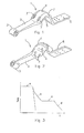
- Fig. 1 an exemplary embodiment of a flexible trailing arm 1 for a wheel axle suspension.
- the shown trailing arm 1 is made from steel and comprises a spring portion 2, a hinge eyelet 3 on the front end of the spring portion 2, a curved portion 4 is formed, which curved portion 4 has a concave contact surface 5 which is directed downward in the example shown.
- an end portion 6 is formed which is intended for fitting a pneumatic spring thereto.
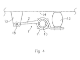
- Fig. 4 an exemplary wheel axle suspension of for example a trailer or a lorry.
- the suspension comprises has a trailing arm 1 which extends substantially in the longitudinal direction of the vehicle.
- the axle body 10 of the wheel axle is attached to the trailing arm 1 at the mounting portion of the trailing arm 1 by means of a clamping member 11.
- Each trailing arm 1 is hingedly connected to a bearing bracket 12, which is arranged on the vehicle chassis 14. Thereto a hinge bolt 15 extends through the bearing bracket 12 and the eyelet 3 at the front end of the trailing arm 1.
- a pneumatic spring 13 or bellows is arranged between a rear end portion 6 of the trailing arm 1 and the chassis 14 of the vehicle.
- the trailing arm may not have an integral end portion 6 for mounting the pneumatic spring 13 to.
- the clamping member may for example be provided with a rearwardly extending support arm for mounting the pneumatic spring to.
- the spring portion 2 of this arm 1 has a substantially rectangular cross section having a width and a thickness, the width being greater than the thickness.
- the spring portion 2 could be produced by rolling, but is preferably produced by forging.
- the curved portion 4 is preferably produced by forging. In this case, four bore holes 7 are provided in the curved portion 4 which serve to insert clamping bolts. This could be U-shaped clamping bolts that engage the axle body (not shown) directly to the concave side of the curved portion 4 of the trailing arm 1 or this could be clamping bolts tensioning the clamping member 11 to the axle body.
- the eyelet 3 can also be forged.
- the trailing arm 1 is formed entirely by hot forging.
- the forging temperature brings the steel to a austenite structure. This is indicated in Fig. 3 with a in the temperature - time curve.
- the forging heat is thereafter used to harden the steel by submerging the trailing arm 1 in a liquid salt bath.
- the temperature of the liquid salt is preferably around 310°C.
- the temperature of the trailing arm thus is lowered from the forging temperature at a to the temperature of the salt at c following the curve b.
- the trailing arm 1 is held in the liquid salt bath for a certain time such that the steel is converted from a austenite structure to a bainite structure. This is indicated by c in the diagram.
- the trailing arm 1 is taken out of the liquid salt bath and is cooled to room temperature in the air, which is indicated by d in the diagram.
Landscapes
- Chemical & Material Sciences (AREA)
- Engineering & Computer Science (AREA)
- Mechanical Engineering (AREA)
- Physics & Mathematics (AREA)
- Thermal Sciences (AREA)
- Crystallography & Structural Chemistry (AREA)
- Materials Engineering (AREA)
- Metallurgy (AREA)
- Organic Chemistry (AREA)
- Vehicle Body Suspensions (AREA)
- Heat Treatment Of Articles (AREA)
Abstract
Description
- The present invention relates to the manufacturing of flexible suspension arms for a wheel axle suspension of a vehicle, such as a lorry or a trailer. Such suspension arms are referred to in the art as flexible trailing arms or spring arms.
- A wheel axle suspension of a trailer or a lorry has a trailing arm on each side of the vehicle which extends substantially in the longitudinal direction of the vehicle. The axle body of the wheel axle is attached to the trailing arms. Each trailing arm is hingedly connected at the front, viewed in the direction of travel of the vehicle, to a bearing bracket which is arranged on the vehicle chassis. Generally, a pneumatic spring is arranged between the trailing arm and the chassis of such a wheel axle suspension. A flexible trailing arm commonly comprises a spring portion, an eyelet at the front end of the spring portion for hingedly mounting the trailing arm to the vehicle, and a mounting portion at the rear end of the spring portion where the wheel axle body can be mounted to the trailing arm.
- In the field of manufacturing flexible trailing arms it is common to manufacture the trailing arms by rolling a heated steel blank into a desired shape of the trailing arm. In general this is the shape of a leaf spring. The trailing arm is commonly shaped in several rolling steps, and possibly bending and cutting steps. The forming includes a step where a hinge eyelet is bended on the front end of the rolled flexible trailing arm. These forming steps take place consecutively and the intermediary product is conveyed between consecutive rolling and bending devices. Before each of the rolling and bending steps the trailing arm may be reheated, at least partly. After the product is entirely shaped it is allowed to cool in air to room temperature. The shaped steel arm is given the desired mechanical properties, in particular the desired tensional strength, by hardening the steel which includes reheating the shaped arm such that the steel becomes an austenite structure and subsequently quenching it in an oil bath of about 80°C, whereby the steel obtains a martensite structure with a sufficient tensile strength for the flexible trailing arm to perform its function properly. The quenching in oil is hazardous in view of fire risks. Furthermore the oil is a danger for the environment. The resulting martensite structure after quenching is very hard and brittle, which is undesired for the flexible trailing arm, which in use is subjected to dynamic loads. Therefore it is necessary to temper the steel after hardening it by reheating it again to a moderately high temperature (e.g. at 180-220°C) and keep it at that temperature for one or two hours.
- The present invention has for an object to provide an alternative method for manufacturing a flexible steel trailing arm.
- This object is achieved by a method for manufacturing a flexible trailing arm for a wheel axle suspension of a vehicle such as a lorry or a trailer, comprising the following steps:
- heating a steel blank,
- forming the blank into the desired shape of the trailing arm by means of a suitable forming process,
- austempering the formed trailing arm by cooling it in a warm liquid medium.
- By this method is obtained a trailing arm with a substantially bainitic structure, at least at the outside regions. A bainitic structure is more ductile than the martensite structure which is common in flexible trailing arms, whereby a tempering step, which is necessary with a martensite structure, can be omitted, which saves energy use and time.
- It is possible that more interior regions of the trailing arm, in particular of the thicker portions of the trailing arm during the austempering are not converted into a bainitic structure but into another structure e.g. pearlite or ferrite structure or a mixture of structures. This may be because said more interior regions are cooled at a different rate than the more exterior regions. The more exterior regions are in use of the trailing arm subjected to the greatest bending loads. It is thus desirable that at least these exterior regions to a certain depth from the outer surface have a bainitic structure. For the interior regions this may be less important since they are subjected to smaller bending loads.
- The flexible trailing arm is preferably cooled in a liquid medium with a temperature of about 310°C.
- Preferably the flexible trailing arm is cooled in a liquid salt, with preferably a temperature of 310°C.
- The method according to the invention can be used with particular advantage when the flexible trailing arm is shaped by means of forging. The trailing arm is then advantageously formed in one forging step, whereby no transport and reheating between forming steps is necessary. Furthermore the forged arm can with particular advantage be submerged directly in the liquid salt after it is ejected or otherwise removed from the forging device. In this manner the formed flexible trailing arm does not have to be reheated to an austenite structure to harden it. The trailing arm is simply formed in one step and then directly out of the forging device austempered in the liquid salt. The resulting trailing arm has a bainitic structure and has a sufficient tensile strength of preferably 1300 - 1600 N/mm2. This specifically advantageous manufacturing method thus provides high quality flexible trailing arms in an efficient way and cost effective way, in which in particular time and energy is saved.
- It is also possible to form the trailing arm by means of forging in a plurality of forging steps.
- Alternatively it is also possible to form the trailing arm by rolling in the common way, after which the trailing arm is austempered in a liquid salt.
- The invention also relates to a flexible trailing arm for a wheel axle suspension of a vehicle such as a lorry or a trailer, wherein the flexible trailing arm comprises steel with a bainitic structure which has a tensile strength of approximately 1300 - 1600 N/mm.
- The invention will be elucidated in the following description with reference to the drawing in which:
-
Fig. 1 shows a perspective view from above of a flexible trailing arm for a wheel axle suspension, -
Fig. 2 shows a perspective view from below of the flexible trailing arm ofFig. 1 , -
Fig. 3 shows a schematical temperature - time curve during hardening, and -
Fig. 4 shows a side view of a wheel axle supension with the trailing arm ofFigs 1 and 2 . - In
Fig. 1 is shown an exemplary embodiment of aflexible trailing arm 1 for a wheel axle suspension. The showntrailing arm 1 is made from steel and comprises aspring portion 2, ahinge eyelet 3 on the front end of thespring portion 2, acurved portion 4 is formed, which curvedportion 4 has aconcave contact surface 5 which is directed downward in the example shown. Following on from thecurved portion 4, anend portion 6 is formed which is intended for fitting a pneumatic spring thereto. - In
Fig. 4 is shown an exemplary wheel axle suspension of for example a trailer or a lorry. On each side of the vehicle, the suspension comprises has atrailing arm 1 which extends substantially in the longitudinal direction of the vehicle. Theaxle body 10 of the wheel axle is attached to thetrailing arm 1 at the mounting portion of thetrailing arm 1 by means of aclamping member 11. Eachtrailing arm 1 is hingedly connected to abearing bracket 12, which is arranged on thevehicle chassis 14. Thereto ahinge bolt 15 extends through thebearing bracket 12 and theeyelet 3 at the front end of thetrailing arm 1. Apneumatic spring 13 or bellows is arranged between arear end portion 6 of the trailingarm 1 and thechassis 14 of the vehicle. - In a possible alternative embodiment of the wheel axle suspension, the trailing arm may not have an
integral end portion 6 for mounting thepneumatic spring 13 to. In such an alternative embodiment the clamping member may for example be provided with a rearwardly extending support arm for mounting the pneumatic spring to. - The
spring portion 2 of thisarm 1 has a substantially rectangular cross section having a width and a thickness, the width being greater than the thickness. Thespring portion 2 could be produced by rolling, but is preferably produced by forging. Thecurved portion 4 is preferably produced by forging. In this case, fourbore holes 7 are provided in thecurved portion 4 which serve to insert clamping bolts. This could be U-shaped clamping bolts that engage the axle body (not shown) directly to the concave side of thecurved portion 4 of thetrailing arm 1 or this could be clamping bolts tensioning theclamping member 11 to the axle body. Theeyelet 3 can also be forged. - Preferably the trailing
arm 1 is formed entirely by hot forging. The forging temperature brings the steel to a austenite structure. This is indicated inFig. 3 with a in the temperature - time curve. The forging heat is thereafter used to harden the steel by submerging the trailingarm 1 in a liquid salt bath. The temperature of the liquid salt is preferably around 310°C. The temperature of the trailing arm thus is lowered from the forging temperature at a to the temperature of the salt at c following the curve b. The trailingarm 1 is held in the liquid salt bath for a certain time such that the steel is converted from a austenite structure to a bainite structure. This is indicated by c in the diagram. After the austempering phase in which bainite is formed, the trailingarm 1 is taken out of the liquid salt bath and is cooled to room temperature in the air, which is indicated by d in the diagram. - The invention can be summarised by the following clauses:
- 1. A method for manufacturing a flexible trailing arm for a wheel axle suspension of a vehicle such as a lorry or a trailer, comprising the following steps:
- heating a steel blank,
- forming the blank into the desired shape of the trailing arm by means of a suitable forming process,
- austempering the formed trailing arm by cooling it in a warm liquid medium.
- 2. Method according to
clause 1, wherein the trailing arm is cooled in the liquid medium to a temperature of about 310°C. - 3. Method according to
clause - 4. Method according to any one of the clauses 1-3, wherein the trailing arm is formed by forging.
- 5. Method according to
clause 4, wherein the trailing arm is submerged in the liquid salt to austemper it directly after forging. - 6. Method according to any one of the clauses 1 - 3, wherein the trailing arm is formed by rolling.
- 7. Method according to
clause 6, wherein the trailing arm is submerged in the liquid salt to austemper it directly after the rolling process. - 8. Method according to any one of the preceding clauses, wherein the trailing arm is heated and austenitised after which it is cooled in the liquid medium to a temperature of about 310°C.
- 9. Flexible trailing arm for a wheel axle suspension of a vehicle such as a lorry or a trailer, wherein the flexible trailing arm comprises steel with a bainitic structure which has a tensile strength of approximately 1300 -1600 N/mm.
Claims (10)
- Flexible trailing arm for a wheel axle suspension of a vehicle such as a lorry or a trailer, with a substantially bainitic structure, wherein at least exterior regions, which extend from the outer surface of the trailing arm to a certain depth, have a bainitic structure.
- Flexible trailing arm according to claim 1, wherein the trailing arm (1) has interior regions, located more to the interior than the exterior regions, which have another structure than bainitic structure e.g. pearlite or ferrite structure or a mixture of structures.
- Flexible trailing arm (1) for a wheel axle suspension of a vehicle such as a lorry or a trailer, wherein the flexible trailing arm (1) comprises steel with a bainitic structure which has a tensile strength of approximately 1300 -1600 N/mm2.
- Flexible trailing arm according to claim 3, wherein the trailing arm (1) has exterior regions which extend from the outer surface to a certain depth, which exterior regions have a bainitic structure.
- Flexible trailing arm according to claim 4, wherein the trailing arm (1) has interior regions, located more to the interior than the exterior regions, which have another structure than bainitic structure e.g. pearlite or ferrite structure or a mixture of structures.
- Flexible trailing arm according to any one of the preceding claims, wherein the trailing arm (1) is a forged part.
- Flexible trailing arm according to any one of the preceding claims, wherein the trailing arm (1) comprises a spring portion (2), a hinge eyelet (3) on a front end of the spring portion (2), and a curved portion (4) on a rear end of the spring portion, which curved portion (4) has a concave contact surface (5).
- Flexible trailing arm according to claim 7, wherein the spring portion (2) of the arm (1) has a substantially rectangular cross section having a width and a thickness, the width being greater than the thickness.
- Wheel axle suspension for a vehicle comprising a flexible trailing arm according to anyone of the preceding claims.
- Vehicle comprising a wheel axle suspension according to claim 9.
Applications Claiming Priority (3)
| Application Number | Priority Date | Filing Date | Title |
|---|---|---|---|
| NL2002248A NL2002248C2 (en) | 2008-11-24 | 2008-11-24 | Hardening of flexible trailing arms. |
| EP09761038A EP2358916B1 (en) | 2008-11-24 | 2009-11-19 | Hardening of flexible trailing arms |
| PCT/NL2009/000226 WO2010059037A1 (en) | 2008-11-24 | 2009-11-19 | Hardening of flexible trailing arms |
Related Parent Applications (2)
| Application Number | Title | Priority Date | Filing Date |
|---|---|---|---|
| EP09761038A Division EP2358916B1 (en) | 2008-11-24 | 2009-11-19 | Hardening of flexible trailing arms |
| EP09761038.0 Division | 2009-11-19 |
Publications (2)
| Publication Number | Publication Date |
|---|---|
| EP2594652A1 true EP2594652A1 (en) | 2013-05-22 |
| EP2594652B1 EP2594652B1 (en) | 2018-09-19 |
Family
ID=40814680
Family Applications (2)
| Application Number | Title | Priority Date | Filing Date |
|---|---|---|---|
| EP09761038A Revoked EP2358916B1 (en) | 2008-11-24 | 2009-11-19 | Hardening of flexible trailing arms |
| EP13154606.1A Not-in-force EP2594652B1 (en) | 2008-11-24 | 2009-11-19 | Hard flexible trailing arms |
Family Applications Before (1)
| Application Number | Title | Priority Date | Filing Date |
|---|---|---|---|
| EP09761038A Revoked EP2358916B1 (en) | 2008-11-24 | 2009-11-19 | Hardening of flexible trailing arms |
Country Status (9)
| Country | Link |
|---|---|
| US (1) | US8480104B2 (en) |
| EP (2) | EP2358916B1 (en) |
| JP (1) | JP2012509989A (en) |
| CN (1) | CN102224264B (en) |
| BR (1) | BRPI0921398A2 (en) |
| CA (1) | CA2744412C (en) |
| ES (1) | ES2407532T3 (en) |
| NL (1) | NL2002248C2 (en) |
| WO (1) | WO2010059037A1 (en) |
Cited By (1)
| Publication number | Priority date | Publication date | Assignee | Title |
|---|---|---|---|---|
| DE102013008877A1 (en) * | 2013-05-27 | 2014-11-27 | Schomäcker Federnwerk GmbH | parable link |
Families Citing this family (10)
| Publication number | Priority date | Publication date | Assignee | Title |
|---|---|---|---|---|
| NL1034756C1 (en) * | 2007-07-20 | 2009-01-21 | Weweler Nv | Wheel axle suspension for use in vehicle e.g. lorry, has trailing arm for attaching axle of wheel of vehicle, which is wider in contact region formed corresponding to outer contour of axle, and clamped with axle |
| US20120161413A1 (en) * | 2010-12-27 | 2012-06-28 | Gowthaman Subbarayalu | Vehicle air suspension |
| EP2812455A1 (en) | 2012-02-10 | 2014-12-17 | Ascometal | Process for making a steel part, and steel part so obtained |
| DE102012207157A1 (en) * | 2012-04-30 | 2013-10-31 | Saf-Holland Gmbh | axle connection |
| US20170183758A1 (en) * | 2014-05-23 | 2017-06-29 | Swamy Kotagiri | Austempering Of Structural Components |
| JP6258243B2 (en) * | 2015-03-23 | 2018-01-10 | 日本発條株式会社 | Stabilizer and manufacturing method thereof |
| CN104988397B (en) * | 2015-07-03 | 2017-08-01 | 李艳 | A kind of tungstenic jib boom |
| CN104988396B (en) * | 2015-07-03 | 2017-12-12 | 嵊州北航投星空众创科技有限公司 | A kind of jib boom containing zirconium |
| CN104988401B (en) * | 2015-07-03 | 2017-07-07 | 中国石油大学(华东) | A kind of jib boom containing tantalum |
| DE102017218795B4 (en) * | 2017-10-20 | 2021-05-27 | Ford Global Technologies, Llc | Axle suspension |
Citations (6)
| Publication number | Priority date | Publication date | Assignee | Title |
|---|---|---|---|---|
| JPS61174333A (en) * | 1985-01-30 | 1986-08-06 | Hitachi Metals Ltd | Manufacture of spring holder |
| JPH07179936A (en) * | 1993-12-24 | 1995-07-18 | Aichi Steel Works Ltd | Steel for thin leaf springs with excellent heat sag |
| JPH08232040A (en) * | 1995-02-24 | 1996-09-10 | Aisin Takaoka Ltd | Spheroidal graphite cast iron with high toughness and its production |
| US6364973B1 (en) * | 1998-04-03 | 2002-04-02 | Daimlerchrysler Ag | Deep-drawn parts made of spring sheet steel which are especially used as a lightweight structural member or vehicle body part, and a method for the production thereof |
| JP2004262453A (en) * | 2004-06-07 | 2004-09-24 | F Tech:Kk | Vehicle suspension arm |
| WO2009014423A1 (en) * | 2007-07-20 | 2009-01-29 | Weweler Nederland B.V. | Wheel axle suspension |
Family Cites Families (14)
| Publication number | Priority date | Publication date | Assignee | Title |
|---|---|---|---|---|
| US3434707A (en) * | 1966-06-02 | 1969-03-25 | John E Raidel | Suspensions |
| WO1981002141A1 (en) * | 1980-01-25 | 1981-08-06 | Ki Inzh Str Inst | Spring and suspension of a vehicle comprising such spring |
| US4392668A (en) * | 1980-12-09 | 1983-07-12 | Mulholland Lawrence K | Shock-absorbing wheel suspension assembly |
| JP2774808B2 (en) * | 1989-02-14 | 1998-07-09 | 日本発条株式会社 | Manufacturing method of high strength spring |
| FR2744733B1 (en) * | 1996-02-08 | 1998-04-24 | Ascometal Sa | STEEL FOR MANUFACTURING FORGED PART AND METHOD FOR MANUFACTURING FORGED PART |
| JPH1142917A (en) * | 1997-07-25 | 1999-02-16 | Nhk Spring Co Ltd | Suspension device for vehicle |
| CN1230599A (en) * | 1998-03-27 | 1999-10-06 | 李昭奇 | Bainite steel plate spring for vehicle and its heat treatment |
| US6805369B2 (en) * | 2000-01-19 | 2004-10-19 | The Holland Group, Inc. | Spring beam suspension with compressed axle mounting |
| US20040025987A1 (en) * | 2002-05-31 | 2004-02-12 | Bhagwat Anand W. | High carbon steel wire with bainitic structure for spring and other cold-formed applications |
| GB0313804D0 (en) * | 2003-06-14 | 2003-07-23 | Meritor Heavy Vehicle Sys Ltd | A suspension trailing arm |
| CN2651066Y (en) * | 2003-10-16 | 2004-10-27 | 上汽集团奇瑞汽车有限公司 | Rear drag arm |
| US7455306B2 (en) * | 2003-10-17 | 2008-11-25 | Hendrickson Usa, L.L.C. | Integral arm axle/suspension system |
| CN100451359C (en) | 2006-06-27 | 2009-01-14 | 奇瑞汽车股份有限公司 | Crankshaft of automobile engine |
| CN201342918Y (en) * | 2009-01-06 | 2009-11-11 | 上海汇众汽车制造有限公司 | An automobile drag arm |
-
2008
- 2008-11-24 NL NL2002248A patent/NL2002248C2/en not_active IP Right Cessation
-
2009
- 2009-11-19 EP EP09761038A patent/EP2358916B1/en not_active Revoked
- 2009-11-19 ES ES09761038T patent/ES2407532T3/en active Active
- 2009-11-19 CA CA2744412A patent/CA2744412C/en not_active Expired - Fee Related
- 2009-11-19 US US13/130,446 patent/US8480104B2/en not_active Expired - Fee Related
- 2009-11-19 EP EP13154606.1A patent/EP2594652B1/en not_active Not-in-force
- 2009-11-19 JP JP2011537380A patent/JP2012509989A/en active Pending
- 2009-11-19 WO PCT/NL2009/000226 patent/WO2010059037A1/en not_active Ceased
- 2009-11-19 CN CN200980146703.2A patent/CN102224264B/en not_active Expired - Fee Related
- 2009-11-19 BR BRPI0921398A patent/BRPI0921398A2/en active Search and Examination
Patent Citations (6)
| Publication number | Priority date | Publication date | Assignee | Title |
|---|---|---|---|---|
| JPS61174333A (en) * | 1985-01-30 | 1986-08-06 | Hitachi Metals Ltd | Manufacture of spring holder |
| JPH07179936A (en) * | 1993-12-24 | 1995-07-18 | Aichi Steel Works Ltd | Steel for thin leaf springs with excellent heat sag |
| JPH08232040A (en) * | 1995-02-24 | 1996-09-10 | Aisin Takaoka Ltd | Spheroidal graphite cast iron with high toughness and its production |
| US6364973B1 (en) * | 1998-04-03 | 2002-04-02 | Daimlerchrysler Ag | Deep-drawn parts made of spring sheet steel which are especially used as a lightweight structural member or vehicle body part, and a method for the production thereof |
| JP2004262453A (en) * | 2004-06-07 | 2004-09-24 | F Tech:Kk | Vehicle suspension arm |
| WO2009014423A1 (en) * | 2007-07-20 | 2009-01-29 | Weweler Nederland B.V. | Wheel axle suspension |
Non-Patent Citations (1)
| Title |
|---|
| R.KEOUGH ET AL.: "ASM Handbook, Vol. 4, Heat Treating", vol. 4, 1 June 1995, ASM INTERNATIONAL, ISBN: 0871703793, pages: 152 - 157, XP002537326 * |
Cited By (1)
| Publication number | Priority date | Publication date | Assignee | Title |
|---|---|---|---|---|
| DE102013008877A1 (en) * | 2013-05-27 | 2014-11-27 | Schomäcker Federnwerk GmbH | parable link |
Also Published As
| Publication number | Publication date |
|---|---|
| BRPI0921398A2 (en) | 2015-12-29 |
| US8480104B2 (en) | 2013-07-09 |
| JP2012509989A (en) | 2012-04-26 |
| CN102224264B (en) | 2014-06-04 |
| CA2744412C (en) | 2015-12-29 |
| CA2744412A1 (en) | 2010-05-27 |
| NL2002248C2 (en) | 2010-05-26 |
| EP2358916A1 (en) | 2011-08-24 |
| CN102224264A (en) | 2011-10-19 |
| EP2594652B1 (en) | 2018-09-19 |
| US20110254243A1 (en) | 2011-10-20 |
| ES2407532T3 (en) | 2013-06-12 |
| EP2358916B1 (en) | 2013-02-20 |
| WO2010059037A1 (en) | 2010-05-27 |
Similar Documents
| Publication | Publication Date | Title |
|---|---|---|
| EP2358916B1 (en) | Hardening of flexible trailing arms | |
| US7010950B2 (en) | Suspension component having localized material strengthening | |
| US7506444B2 (en) | Vehicle suspension control arm and method | |
| US6523841B2 (en) | Twist-beam axle for motor vehicles | |
| EP3231879B1 (en) | Production method for stabilizers | |
| CN106494175B (en) | Stabilizer bar and process for manufacturing stabilizer bar | |
| US11111554B2 (en) | Stabilizer | |
| JP6494357B2 (en) | Method for manufacturing hollow stabilizer | |
| CN110249062B (en) | Method for producing wheels in sheet construction | |
| WO2016158408A1 (en) | Method for manufacturing spring for suspension device, and spring for suspension device | |
| US20210078635A1 (en) | An Improved Cross Member and Cross Member Assembly for a Vehicle Frame | |
| JP4225178B2 (en) | Connecting rod manufacturing method and manufacturing apparatus | |
| WO2015179752A1 (en) | Austempering of structural components |
Legal Events
| Date | Code | Title | Description |
|---|---|---|---|
| PUAI | Public reference made under article 153(3) epc to a published international application that has entered the european phase |
Free format text: ORIGINAL CODE: 0009012 |
|
| AC | Divisional application: reference to earlier application |
Ref document number: 2358916 Country of ref document: EP Kind code of ref document: P |
|
| AK | Designated contracting states |
Kind code of ref document: A1 Designated state(s): AT BE BG CH CY CZ DE DK EE ES FI FR GB GR HR HU IE IS IT LI LT LU LV MC MK MT NL NO PL PT RO SE SI SK SM TR |
|
| 17P | Request for examination filed |
Effective date: 20130923 |
|
| RBV | Designated contracting states (corrected) |
Designated state(s): AT BE BG CH CY CZ DE DK EE ES FI FR GB GR HR HU IE IS IT LI LT LU LV MC MK MT NL NO PL PT RO SE SI SK SM TR |
|
| 17Q | First examination report despatched |
Effective date: 20131220 |
|
| GRAP | Despatch of communication of intention to grant a patent |
Free format text: ORIGINAL CODE: EPIDOSNIGR1 |
|
| INTG | Intention to grant announced |
Effective date: 20171023 |
|
| GRAJ | Information related to disapproval of communication of intention to grant by the applicant or resumption of examination proceedings by the epo deleted |
Free format text: ORIGINAL CODE: EPIDOSDIGR1 |
|
| GRAP | Despatch of communication of intention to grant a patent |
Free format text: ORIGINAL CODE: EPIDOSNIGR1 |
|
| INTC | Intention to grant announced (deleted) | ||
| RAP1 | Party data changed (applicant data changed or rights of an application transferred) |
Owner name: VDL WEWELER B.V. |
|
| INTG | Intention to grant announced |
Effective date: 20180328 |
|
| GRAS | Grant fee paid |
Free format text: ORIGINAL CODE: EPIDOSNIGR3 |
|
| GRAA | (expected) grant |
Free format text: ORIGINAL CODE: 0009210 |
|
| AC | Divisional application: reference to earlier application |
Ref document number: 2358916 Country of ref document: EP Kind code of ref document: P |
|
| AK | Designated contracting states |
Kind code of ref document: B1 Designated state(s): AT BE BG CH CY CZ DE DK EE ES FI FR GB GR HR HU IE IS IT LI LT LU LV MC MK MT NL NO PL PT RO SE SI SK SM TR |
|
| REG | Reference to a national code |
Ref country code: GB Ref legal event code: FG4D |
|
| REG | Reference to a national code |
Ref country code: CH Ref legal event code: EP |
|
| REG | Reference to a national code |
Ref country code: AT Ref legal event code: REF Ref document number: 1043351 Country of ref document: AT Kind code of ref document: T Effective date: 20181015 |
|
| REG | Reference to a national code |
Ref country code: IE Ref legal event code: FG4D |
|
| REG | Reference to a national code |
Ref country code: DE Ref legal event code: R096 Ref document number: 602009054686 Country of ref document: DE |
|
| REG | Reference to a national code |
Ref country code: NL Ref legal event code: MP Effective date: 20180919 |
|
| PG25 | Lapsed in a contracting state [announced via postgrant information from national office to epo] |
Ref country code: FI Free format text: LAPSE BECAUSE OF FAILURE TO SUBMIT A TRANSLATION OF THE DESCRIPTION OR TO PAY THE FEE WITHIN THE PRESCRIBED TIME-LIMIT Effective date: 20180919 Ref country code: SE Free format text: LAPSE BECAUSE OF FAILURE TO SUBMIT A TRANSLATION OF THE DESCRIPTION OR TO PAY THE FEE WITHIN THE PRESCRIBED TIME-LIMIT Effective date: 20180919 Ref country code: NO Free format text: LAPSE BECAUSE OF FAILURE TO SUBMIT A TRANSLATION OF THE DESCRIPTION OR TO PAY THE FEE WITHIN THE PRESCRIBED TIME-LIMIT Effective date: 20181219 Ref country code: LT Free format text: LAPSE BECAUSE OF FAILURE TO SUBMIT A TRANSLATION OF THE DESCRIPTION OR TO PAY THE FEE WITHIN THE PRESCRIBED TIME-LIMIT Effective date: 20180919 Ref country code: BG Free format text: LAPSE BECAUSE OF FAILURE TO SUBMIT A TRANSLATION OF THE DESCRIPTION OR TO PAY THE FEE WITHIN THE PRESCRIBED TIME-LIMIT Effective date: 20181219 Ref country code: GR Free format text: LAPSE BECAUSE OF FAILURE TO SUBMIT A TRANSLATION OF THE DESCRIPTION OR TO PAY THE FEE WITHIN THE PRESCRIBED TIME-LIMIT Effective date: 20181220 |
|
| REG | Reference to a national code |
Ref country code: LT Ref legal event code: MG4D |
|
| PG25 | Lapsed in a contracting state [announced via postgrant information from national office to epo] |
Ref country code: HR Free format text: LAPSE BECAUSE OF FAILURE TO SUBMIT A TRANSLATION OF THE DESCRIPTION OR TO PAY THE FEE WITHIN THE PRESCRIBED TIME-LIMIT Effective date: 20180919 Ref country code: LV Free format text: LAPSE BECAUSE OF FAILURE TO SUBMIT A TRANSLATION OF THE DESCRIPTION OR TO PAY THE FEE WITHIN THE PRESCRIBED TIME-LIMIT Effective date: 20180919 |
|
| REG | Reference to a national code |
Ref country code: AT Ref legal event code: MK05 Ref document number: 1043351 Country of ref document: AT Kind code of ref document: T Effective date: 20180919 |
|
| PG25 | Lapsed in a contracting state [announced via postgrant information from national office to epo] |
Ref country code: NL Free format text: LAPSE BECAUSE OF FAILURE TO SUBMIT A TRANSLATION OF THE DESCRIPTION OR TO PAY THE FEE WITHIN THE PRESCRIBED TIME-LIMIT Effective date: 20180919 Ref country code: IS Free format text: LAPSE BECAUSE OF FAILURE TO SUBMIT A TRANSLATION OF THE DESCRIPTION OR TO PAY THE FEE WITHIN THE PRESCRIBED TIME-LIMIT Effective date: 20190119 Ref country code: CZ Free format text: LAPSE BECAUSE OF FAILURE TO SUBMIT A TRANSLATION OF THE DESCRIPTION OR TO PAY THE FEE WITHIN THE PRESCRIBED TIME-LIMIT Effective date: 20180919 Ref country code: RO Free format text: LAPSE BECAUSE OF FAILURE TO SUBMIT A TRANSLATION OF THE DESCRIPTION OR TO PAY THE FEE WITHIN THE PRESCRIBED TIME-LIMIT Effective date: 20180919 Ref country code: ES Free format text: LAPSE BECAUSE OF FAILURE TO SUBMIT A TRANSLATION OF THE DESCRIPTION OR TO PAY THE FEE WITHIN THE PRESCRIBED TIME-LIMIT Effective date: 20180919 Ref country code: PL Free format text: LAPSE BECAUSE OF FAILURE TO SUBMIT A TRANSLATION OF THE DESCRIPTION OR TO PAY THE FEE WITHIN THE PRESCRIBED TIME-LIMIT Effective date: 20180919 Ref country code: EE Free format text: LAPSE BECAUSE OF FAILURE TO SUBMIT A TRANSLATION OF THE DESCRIPTION OR TO PAY THE FEE WITHIN THE PRESCRIBED TIME-LIMIT Effective date: 20180919 Ref country code: AT Free format text: LAPSE BECAUSE OF FAILURE TO SUBMIT A TRANSLATION OF THE DESCRIPTION OR TO PAY THE FEE WITHIN THE PRESCRIBED TIME-LIMIT Effective date: 20180919 Ref country code: IT Free format text: LAPSE BECAUSE OF FAILURE TO SUBMIT A TRANSLATION OF THE DESCRIPTION OR TO PAY THE FEE WITHIN THE PRESCRIBED TIME-LIMIT Effective date: 20180919 |
|
| PG25 | Lapsed in a contracting state [announced via postgrant information from national office to epo] |
Ref country code: SM Free format text: LAPSE BECAUSE OF FAILURE TO SUBMIT A TRANSLATION OF THE DESCRIPTION OR TO PAY THE FEE WITHIN THE PRESCRIBED TIME-LIMIT Effective date: 20180919 Ref country code: SK Free format text: LAPSE BECAUSE OF FAILURE TO SUBMIT A TRANSLATION OF THE DESCRIPTION OR TO PAY THE FEE WITHIN THE PRESCRIBED TIME-LIMIT Effective date: 20180919 Ref country code: PT Free format text: LAPSE BECAUSE OF FAILURE TO SUBMIT A TRANSLATION OF THE DESCRIPTION OR TO PAY THE FEE WITHIN THE PRESCRIBED TIME-LIMIT Effective date: 20190119 |
|
| REG | Reference to a national code |
Ref country code: DE Ref legal event code: R097 Ref document number: 602009054686 Country of ref document: DE |
|
| REG | Reference to a national code |
Ref country code: CH Ref legal event code: PL |
|
| PLBE | No opposition filed within time limit |
Free format text: ORIGINAL CODE: 0009261 |
|
| STAA | Information on the status of an ep patent application or granted ep patent |
Free format text: STATUS: NO OPPOSITION FILED WITHIN TIME LIMIT |
|
| PG25 | Lapsed in a contracting state [announced via postgrant information from national office to epo] |
Ref country code: MC Free format text: LAPSE BECAUSE OF FAILURE TO SUBMIT A TRANSLATION OF THE DESCRIPTION OR TO PAY THE FEE WITHIN THE PRESCRIBED TIME-LIMIT Effective date: 20180919 Ref country code: DK Free format text: LAPSE BECAUSE OF FAILURE TO SUBMIT A TRANSLATION OF THE DESCRIPTION OR TO PAY THE FEE WITHIN THE PRESCRIBED TIME-LIMIT Effective date: 20180919 Ref country code: LU Free format text: LAPSE BECAUSE OF NON-PAYMENT OF DUE FEES Effective date: 20181119 |
|
| REG | Reference to a national code |
Ref country code: BE Ref legal event code: MM Effective date: 20181130 |
|
| REG | Reference to a national code |
Ref country code: IE Ref legal event code: MM4A |
|
| 26N | No opposition filed |
Effective date: 20190620 |
|
| GBPC | Gb: european patent ceased through non-payment of renewal fee |
Effective date: 20181219 |
|
| PG25 | Lapsed in a contracting state [announced via postgrant information from national office to epo] |
Ref country code: CH Free format text: LAPSE BECAUSE OF NON-PAYMENT OF DUE FEES Effective date: 20181130 Ref country code: LI Free format text: LAPSE BECAUSE OF NON-PAYMENT OF DUE FEES Effective date: 20181130 |
|
| PG25 | Lapsed in a contracting state [announced via postgrant information from national office to epo] |
Ref country code: SI Free format text: LAPSE BECAUSE OF FAILURE TO SUBMIT A TRANSLATION OF THE DESCRIPTION OR TO PAY THE FEE WITHIN THE PRESCRIBED TIME-LIMIT Effective date: 20180919 Ref country code: FR Free format text: LAPSE BECAUSE OF NON-PAYMENT OF DUE FEES Effective date: 20181119 Ref country code: IE Free format text: LAPSE BECAUSE OF NON-PAYMENT OF DUE FEES Effective date: 20181119 |
|
| PG25 | Lapsed in a contracting state [announced via postgrant information from national office to epo] |
Ref country code: BE Free format text: LAPSE BECAUSE OF NON-PAYMENT OF DUE FEES Effective date: 20181130 |
|
| PG25 | Lapsed in a contracting state [announced via postgrant information from national office to epo] |
Ref country code: GB Free format text: LAPSE BECAUSE OF NON-PAYMENT OF DUE FEES Effective date: 20181219 |
|
| PG25 | Lapsed in a contracting state [announced via postgrant information from national office to epo] |
Ref country code: MT Free format text: LAPSE BECAUSE OF NON-PAYMENT OF DUE FEES Effective date: 20181119 |
|
| PG25 | Lapsed in a contracting state [announced via postgrant information from national office to epo] |
Ref country code: TR Free format text: LAPSE BECAUSE OF FAILURE TO SUBMIT A TRANSLATION OF THE DESCRIPTION OR TO PAY THE FEE WITHIN THE PRESCRIBED TIME-LIMIT Effective date: 20180919 |
|
| PG25 | Lapsed in a contracting state [announced via postgrant information from national office to epo] |
Ref country code: HU Free format text: LAPSE BECAUSE OF FAILURE TO SUBMIT A TRANSLATION OF THE DESCRIPTION OR TO PAY THE FEE WITHIN THE PRESCRIBED TIME-LIMIT; INVALID AB INITIO Effective date: 20091119 Ref country code: CY Free format text: LAPSE BECAUSE OF FAILURE TO SUBMIT A TRANSLATION OF THE DESCRIPTION OR TO PAY THE FEE WITHIN THE PRESCRIBED TIME-LIMIT Effective date: 20180919 Ref country code: MK Free format text: LAPSE BECAUSE OF NON-PAYMENT OF DUE FEES Effective date: 20180919 |
|
| PGFP | Annual fee paid to national office [announced via postgrant information from national office to epo] |
Ref country code: DE Payment date: 20231120 Year of fee payment: 15 |
|
| REG | Reference to a national code |
Ref country code: DE Ref legal event code: R119 Ref document number: 602009054686 Country of ref document: DE |
|
| PG25 | Lapsed in a contracting state [announced via postgrant information from national office to epo] |
Ref country code: DE Free format text: LAPSE BECAUSE OF NON-PAYMENT OF DUE FEES Effective date: 20250603 |