EP2594454A1 - Steering device - Google Patents
Steering device Download PDFInfo
- Publication number
- EP2594454A1 EP2594454A1 EP11775902.7A EP11775902A EP2594454A1 EP 2594454 A1 EP2594454 A1 EP 2594454A1 EP 11775902 A EP11775902 A EP 11775902A EP 2594454 A1 EP2594454 A1 EP 2594454A1
- Authority
- EP
- European Patent Office
- Prior art keywords
- tilt
- movable
- lock gear
- cam
- stationary cam
- Prior art date
- Legal status (The legal status is an assumption and is not a legal conclusion. Google has not performed a legal analysis and makes no representation as to the accuracy of the status listed.)
- Granted
Links
- 230000002093 peripheral effect Effects 0.000 claims description 34
- 230000005489 elastic deformation Effects 0.000 description 8
- 229920003002 synthetic resin Polymers 0.000 description 6
- 239000000057 synthetic resin Substances 0.000 description 6
- 239000002184 metal Substances 0.000 description 5
- 229910052751 metal Inorganic materials 0.000 description 5
- 229920006324 polyoxymethylene Polymers 0.000 description 4
- 239000002775 capsule Substances 0.000 description 3
- 230000014759 maintenance of location Effects 0.000 description 3
- 150000002739 metals Chemical class 0.000 description 3
- 229930182556 Polyacetal Natural products 0.000 description 2
- 238000005299 abrasion Methods 0.000 description 2
- 238000010438 heat treatment Methods 0.000 description 2
- 239000000463 material Substances 0.000 description 2
- 238000003466 welding Methods 0.000 description 2
- 230000002159 abnormal effect Effects 0.000 description 1
- 238000005452 bending Methods 0.000 description 1
- 230000000903 blocking effect Effects 0.000 description 1
- 230000000694 effects Effects 0.000 description 1
- 230000001105 regulatory effect Effects 0.000 description 1
- 230000000630 rising effect Effects 0.000 description 1
Images


Classifications
-
- B—PERFORMING OPERATIONS; TRANSPORTING
- B62—LAND VEHICLES FOR TRAVELLING OTHERWISE THAN ON RAILS
- B62D—MOTOR VEHICLES; TRAILERS
- B62D1/00—Steering controls, i.e. means for initiating a change of direction of the vehicle
- B62D1/02—Steering controls, i.e. means for initiating a change of direction of the vehicle vehicle-mounted
- B62D1/16—Steering columns
- B62D1/18—Steering columns yieldable or adjustable, e.g. tiltable
- B62D1/184—Mechanisms for locking columns at selected positions
-
- B—PERFORMING OPERATIONS; TRANSPORTING
- B62—LAND VEHICLES FOR TRAVELLING OTHERWISE THAN ON RAILS
- B62D—MOTOR VEHICLES; TRAILERS
- B62D1/00—Steering controls, i.e. means for initiating a change of direction of the vehicle
- B62D1/02—Steering controls, i.e. means for initiating a change of direction of the vehicle vehicle-mounted
- B62D1/16—Steering columns
- B62D1/18—Steering columns yieldable or adjustable, e.g. tiltable
- B62D1/187—Steering columns yieldable or adjustable, e.g. tiltable with tilt adjustment; with tilt and axial adjustment
Definitions
- the present invention relates to a steering device, and more particularly to a steering device of a tilt type or a tilt and telescopic type combining a telescopic type with the tilt type in which a tilt position of a steering wheel can be adjusted according to a body type or a driving posture of a driver.
- a tilt position adjustment mechanism is a mechanism for adjusting an inclination angle of the steering wheel to the best driving position according to the body type or preference of the driver. In adjusting the inclination angle of the steering wheel, after the inclination angle of the steering wheel is adjusted steplessly in a state where a tilt clamp mechanism is unclamped once, the tilt clamp mechanism is again clamped.
- a vehicle body attachment bracket is fixed to a vehicle body, and a fastening rod is allowed to insert into a tilt adjustment slender groove and a column of the vehicle body attachment bracket.
- a stationary cam is pressed in an axial direction by a movable cam that rotates due to the operation of an operating lever to fasten the fastening rod, and the column is pressed toward the vehicle body attachment bracket for clamping.
- the stationary cam has a cam surface for relatively pressing the movable cam toward the stationary cam in the axial direction, and a locking unit for disabling the stationary cam to be relatively rotated with respect to the movable cam, and for sliding along the tilt adjustment slender groove at the time of adjusting the tilt position. Accordingly, the stationary cam requires both characteristics of durability for allowing a cam surface to withstand a large clamp force, and an impact reduction capability for reducing an impact sound when the locking unit is abutted against the tilt adjustment slender groove at an adjustment end of the tilt position.
- the stationary cam of the steering device disclosed in Patent document 1 integrally couples two parts consisting of a cammember having a cam surface made of a high-hardness material and a locking unit made of a synthetic resin to provide those characteristics described above.
- the column is caused to move in a tilt direction during a secondary collision where a driver collides with the steering wheel, resulting in a risk that an air bag disposed in the steering wheel cannot accept an occupant at an effective position.
- a tilt lock mechanism in which a stationary tilt lock gear is disposed on the vehicle body attachment bracket side, and a movable tilt lock gear the is engaged with the stationary tilt lock gear is inserted into the fastening rod.
- the fastening rod is fastened to engage the movable tilt lock gear with the stationary tilt lock gear, thereby improving a retention force in the tilt direction, with the result that even if an impact load due to the secondary collision is exerted on the steering wheel, the column is not moved in the tilt direction.
- the respective threads of the movable tilt lock gear and the stationary tilt lock gear may be abutted against each other depending on the tilt position, thereby disabling normal engagement.
- the tilt lock becomes insufficient, and when the fastening rod is forcedly fastened, the movable tilt lock gear and the stationary tilt lock gear are strongly rubbed with each other, thereby causing discomfort for the driver.
- the movable tilt lock gear is movably fitted onto the stationary cam in the tilt direction, and the movement of the movable tilt lock gear in the tilt direction with respect to the stationary cam is elastically supported by a spring to provide the degree of freedom of a position at which the movable tilt lock gear and the stationary tilt lock gear are engaged with each other.
- the present invention aims at providing a steering device that facilitates the assembling of a tilt lock mechanism that elastically supports the movement of a movable tilt lock gear with respect to a stationary cam in a tilt direction by the aid of a spring, and also provides the stationary cam having both characteristics of the durability and the impact reduction capability.
- a steering device comprising: a vehicle body attachment bracket that can be attached to a vehicle body; a column that is supported by the vehicle body attachment bracket so that a tilt position is adjustable, and rotatably pivotally supports a steering shaft equipped with a steering wheel; a fastening rod that is inserted into a tilt adjustment slender groove formed in the vehicle body attachment bracket and the column in order to fasten the column to the vehicle body attachment bracket at a desired tilt position; a stationary cam that is supported by one end of the fastening rod, and presses one side of the vehicle body attachment bracket toward the column; a movable cam that is rotatably supported by one end of the fastening rod together with an operating lever so as to face the stationary cam; a cam surface that is disposed on respective surfaces that face the stationary cam and the movable cam, and presses the movable cam toward the stationary cam relatively in an axial direction; a locking unit that
- the tilt stopper is fitted into the tilt adjustment slender groove, is slidable along the tilt adjustment slender groove when adjusting the tilt position of the column, and abuts against an end of the tilt adjustment slender groove at the tilt adjustment end to reduce an impact.
- the tilt stopper comprises: a flange that is fitted into the tilt adjustment slender groove, and is slidable along the tilt adjustment slender groove when adjusting the tilt position of the column; and a space part that is formed in the vicinity of an end surface of the flange in the tilt adjustment direction, and reduces the impact when the flange is abutted against the tilt adjustment end of the tilt adjustment slender groove.
- the tilt stopper comprises: a cylinder part that is formed integrally with the flange, and fitted into a through hole formed in an axial core of the stationary cam; an engagement projection that is formed on an end of the cylindrical part, projects outwardly from an outer peripheral surface of the cylindrical part in a radial direction thereof, and is engageable with an end surface of a cam surface side of the stationary cam; and a through hole that is formed in the axial core of the cylindrical part, into which the fastening rod is inserted, in which the stationary cam, the movable tilt lock gear, and the spring are held between the end surface of the flange and the engagement projection integrally.
- the tilt stopper is symmetric with respect to a line that passes through the center of the tilt stopper as the axis of symmetry.
- the steering device includes the stationary tilt lock gear formed on one side of the vehicle body attachment bracket, the movable tilt lock gear that rotates in synchronism with rotating operation of the operating lever, can be engaged with the stationary tile lock gear, and is fitted onto the stationary cam so as to be movable in a tilt direction, the spring that is inserted between the movable tilt lock gear and the stationary cam, and elastically supports movement of the movable tilt lock gear to the stationary cam in the tilt direction, and the tilt stopper that holds the stationary cam, the movable tilt lock gear, and the spring integrally.
- the tilt stopper is fitted into the tilt adjustment slender groove, is slidable along the tilt adjustment slender groove when adjusting the tilt position of the column, and abuts against an end of the tilt adjustment slender groove at the tilt adjustment end to reduce the impact.
- the stationary cam, the movable tilt lock gear, and the spring can be integrally held by the tilt stopper, those parts can be dealt with as one part, and the assembling time can be reduced. Also, because the tilt stopper and the stationary cam are configured by separate parts, it is easy to provide both characteristics of the durability and the impact reduction capability.
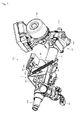
- FIG. 1 is an entire perspective view illustrating a state in which a steering device 101 is attached to a vehicle according to the present invention.
- the steering device 101 rotatably pivotally supports a steering shaft 102.
- a steering wheel 103 is installed to an upper end (vehicle body rear side) of the steering shaft 102, and an intermediate shaft 105 is coupled to a lower end (vehicle body front side) of the steering shaft 102 through a universal joint 104.
- a universal joint 106 is coupled to a lower end of the intermediate shaft 105, and a steering gear 107 formed of a rack and pinion mechanism is coupled to the universal joint 106.
- FIG. 2 is a perspective view illustrating a main portion of the steering device 101 viewed from top left of a backward of a vehicle body according to an embodiment of the present invention.
- FIG. 3 is a perspective view illustrating a main portion of the steering device 101 viewed from bottom right of the backward of the vehicle body according to the embodiment of the present invention.
- FIG. 4 is an exploded perspective view illustrating a vehicle body attachment bracket periphery viewed from top left of the backward of the vehicle body.
- FIG. 5 is an exploded perspective view illustrating the vehicle body attachment bracket periphery viewed from bottom right of the backward of the vehicle body.
- FIG. 6 is an exploded perspective view in which the vehicle body attachment bracket is omitted from FIG. 5 .
- the steering device 101 includes a vehicle body attachment bracket 2, an inner column (lower column) 31, a steering assist unit 32 (power assist mechanism), and an outer column (upper column) 34.
- the vehicle body rear end of the steering assist unit (power assist mechanism) 32 is fixed to the vehicle body front side (left side of FIG. 2 ) of the inner column 31 by press fitting.
- the steering assist unit 32 includes an electric motor 321, a reduction gear box unit 322, and an output shaft 323.
- a bracket 33 formed integrally with the vehicle body front end of the steering assist unit 32 is supported to a vehicle body not shown through a tilt center shaft not shown so as to adjust a tilt position.
- An inner peripheral surface of the outer column 34 is fitted onto an outer peripheral surface of the inner column 31 so as to adjust a telescopic position (slidable in parallel to a center axial line of the inner column 31).
- An upper steering shaft 102A is rotatably pivotally supported by the outer column 34, and the steering wheel 103 (refer to FIG. 1 ) is fixed to the vehicle body rear side (right side of Fig. 2 ) of the upper steering shaft 102A.
- a slit (not shown) that penetrates from an outer peripheral surface to an inner peripheral surface of the outer column 34 is formed in the vehicle body lower side of the outer column 34. The slit is shaped to be opened at the vehicle body front end side of the outer column 34, and closed at the vehicle body rear end.
- a lower steering shaft is rotatably pivotally supported by the inner column 31, and the lower steering shaft is spline-fitted to the upper steering shaft 102A. Accordingly, the rotation of the upper steering shaft 102A is transmitted to the lower steering shaft regardless of the telescopic position of the outer column 34.
- the steering assist unit 32 detects a torque exerted on the lower steering shaft, drives the electric motor 321, and rotates the output shaft 323 by a required steering assist force.
- the rotation of the output shaft 323 is transmitted to the steering gear 107 through the universal joint 104, the intermediate shaft 105, and the universal joint 106 so that the steering angle of the wheel can be changed while assisting the steering force.
- the vehicle body attachment bracket 2 that holds the outer column 34 from both sides thereof in the vehicle width direction is attached to the vehicle body front side (left side of FIG. 2 , right side of FIG. 3 ) of the outer column 34.
- the vehicle body attachment bracket 2 is made of metal, and includes an upper plate 23 formed substantially horizontally in the vehicle width direction, and a pair of right and left side plates 24 and 25 that extend from the upper plate 23 toward the vehicle body lower side, and hold the outer column 34 from both sides thereof in the vehicle width direction.
- Notch grooves (vehicle body rear sides are opened) not shown are formed in both sides of the upper plate 23 in the vehicle width direction, and the upper plate 23 is attached to the vehicle body through two capsules 22 fitted into the notch grooves.
- the vehicle body attachment bracket 2 When the driver collision collides with the steering wheel 103 to exert a large impact force during the secondary collision, the vehicle body attachment bracket 2 is detached from the capsules 22 toward the vehicle body front side. Then, the vehicle body attachment bracket 2 and the outer column 34 are collapse-moved to the vehicle body front side while being guided to the inner column 31, and absorb an impact energy during collision.
- a pair of clamp members, not shown, which projects from the outer column 34 toward the outside in the vehicle width direction are integrally formed on the vehicle body front side of the outer column 34.
- a telescopic adjustment slender groove not shown which longwise extends in the axial direction of the outer column 34 is formed in the clamp member.
- tilt adjustment slender grooves 26 and 27 are formed in the side plates 24 and 25 of the vehicle body attachment bracket 2, respectively.
- the tilt adjustment slender grooves 26 and 27 are formed in an arc shape centered on a tilt center axis.
- An outer surface of the clamp member of the outer column 34 slidably contacts inner surfaces 242 and 252 of the side plates 24 and 25 of the vehicle body attachment bracket 2.
- a round bar shaped fastening rod 41 is inserted through the tilt adjustment slender grooves 26 and 27 and the telescopic adjustment slender groove from right sides of FIGS. 4 and 6 .
- a tilt stopper 48 is fitted onto the fastening rod 41, and a left end of the fastening rod 41 is allowed to pass through the right tilt adjustment slender groove 27, the right telescopic adjustment slender groove, the left telescopic adjustment slender groove, and the left tilt adjustment slender groove 26.
- a tilt stopper 5, a movable tilt lock gear 6, a wire spring (spring) 69, a stationary cam 8, a movable cam 42, an operating lever 43, a collar 44, and a thrust bearing 45 are fitted onto the left end side of the fastening rod 41 in the order from right. Then, a nut 46 is fastened to a left end of the fastening rod 41 for fixation.
- the stationary cam 8 and the movable cam 42 are each made of a sintered material, and subjected to a heat treatment for providing high hardness, and therefore provide durability for withstanding a large clamp force.
- a rectangular locking unit 412 is formed on a disc-shaped head 411 at a right end of the fastening rod 41.
- the rectangular locking unit 412 is fitted to the right tilt adjustment slender groove 27, and the fastening rod 41 is locked with respect to the side plate 24.
- the right tilt stopper 48 is made of a synthetic resin, has a substantially rectangular configuration longitudinal in the tilt direction, and is formed with a width across flat having substantially the same dimension as the groove width of the tilt adjustment slender groove 27.
- the right tilt stopper 48 is fitted into the tilt adjustment slender groove 27, smoothly slides in a tilt adjustment direction when adjusting the tilt position of the outer column 34, and abuts against an end of the tilt adjustment slender groove 27 at the tilt adjustment end for reduction of the impact.
- the movable cam 42 is fitted into the operating lever 43, and rotates integrally with the operating lever 43.
- the operating lever 43 is made of a synthetic resin such as polyacetal (POM) which is excellent in a mechanical property and small in abrasion or friction coefficient.
- a rib 243 that is bent from the side plate 24 toward the outside in the vehicle width direction at a right angle is formed at the vehicle body rear end of the left side plate 24.
- the rib 243 is formed along the tilt adjustment slender groove 26 in the vicinity of the tilt adjustment slender groove 26.
- an upper end of the vehicle body of the rib 243 is fixed to the upper plate 23 of the vehicle body attachment bracket 2 by welding.
- a lower end of the vehicle body of the rib 243 extends up to an upper end of a stationary tilt lock gear 47 that will be described later, but may extend down to a lower end of the stationary tilt lock gear 47. Accordingly, the rib 243 provides the large rigidity of the side plates 24 and 25 in the vicinity of the tilt adjustment slender groove 26, and when the operating lever 43 is rotationally operated in order that the outer column 34 is clamped to the vehicle body attachment bracket 2, the elastic deformation of the side plate 24 is suppressed.
- the vehicle body upper end of the right side plate 25 has a vehicle front side fixed to the upper plate 23 of the vehicle body attachment bracket 2 by welding. Also, a gap 253 is formed between a vehicle rear side of the vehicle body upper end of the right side plate 25 and the upper plate 23 of the vehicle body attachment bracket 2. Accordingly, the gap 253 provides the small rigidity of the side plate 25 in the vicinity of the tilt adjustment slender groove 27, and the elastic deformation of the side plate 25 is facilitated when the operating lever 43 is rotationally operated in order that the outer column 34 is clamped to the vehicle body attachment bracket 2.
- FIG. 7 illustrates a state in which the movable tilt lock gear 6, the stationary cam 8, and the wire spring 69 are assembled integrally by the tilt stopper 5, in which FIG. 7 (a) is a perspective view taken from an inclined cam surface side of the stationary cam 8, and FIG. 7 (b) is a perspective view taken from a rear side of FIG. 7 (a) .
- FIG. 8 illustrates a state in which the movable tilt lock gear 6, the stationary cam 8, and the wire spring 69 are assembled integrally by the tilt stopper 5, in which FIG.
- FIG. 8 (a) is a front view thereof
- FIG. 8(b) is a cross-sectional view taken along a line A-A of FIG. 8(a)
- FIG. 8(c) is a cross-sectional view taken along a line B-B of FIG. 8(a)
- FIG. 8(d) is a view taken in the direction of an arrow P in FIG. 8(a)
- FIG. 9(a) is a view taken in the direction of an arrow Q in FIG. 8(b)
- FIG. 9(b) is a front view illustrating a state in which the tilt stopper is removed from FIG. 9(a) .
- FIG. 10(a) is a perspective view illustrating a state in which the stationary cam 8, the wire spring 69, and the tilt stopper 5 are removed from FIG. 7(a)
- FIG. 10(b) is a perspective view illustrating a state in which the stationary cam 8, the wire spring 69, and the tilt stopper 5 are removed from FIG. 7(b)
- FIG. 11 illustrates an engagement state of the stationary cam 8 and the wire spring 69, in which FIG. 11(a) is a perspective view taken from the inclined cam surface side of the stationary cam 8, FIG. 11 (b) is a perspective view taken from a locking unit side of the stationary cam 8, and FIG. 11 (c) is a front view taken from the locking unit side of the stationary cam 8.
- the movable tilt lock gear 6 is made of metal, and formed to be slender in the vertical direction of the vehicle body, and gears 61 are formed on the vehicle body lower side of the movable tilt lock gear 6 on both sides in the vehicle width direction.
- the gears 61 are longitudinal in the lateral direction of FIG. 8 (a) and tapered, and a plurality of the gears 61 is formed in the vertical direction of the vehicle body.
- the stationary tilt lock gear 47 is fixed onto an outer surface 241 of the left side plate 24 with a bolt 477.
- the stationary tilt lock gear 47 is bent in a U-shape so that the vehicle body front side is opened, and a plurality of gears (refer to FIG. 19(b) ) 471 is formed in the vertical direction of the vehicle body on both inner sides thereof in the vehicle width direction.
- a projection 62 is formed on an outer surface of the movable tilt lock gear 6 in the vehicle width direction, and the projection 62 is engaged with a recess 431 (refer to FIG. 6 ) formed in the operating lever 43. Accordingly, the movable tilt lock gear 6 rotates in synchronism with the rotating operation of the operating lever 43.
- the operating lever 43 is rotated counterclockwise in order to clamp the outer column 34 to the vehicle body attachment bracket 2, the movable tilt lock gear 6 is also rotated counterclockwise, and the gear 61 of the movable tilt lock gear 6 is engaged with the gears 471 of the stationary tilt lock gear 47 to provide a high retention force in the tilt direction.
- the movable tilt lock gear 6 When the operating lever 43 is rotated clockwise in order to unclamp the outer column 34 from the vehicle body attachment bracket 2, the movable tilt lock gear 6 also rotates clockwise, and the gear 61 of the movable tilt lock gear 6 is withdrawn from the gears 471 of the stationary tilt lock gear 47.
- a through hole 63 that is parallel to the axial core of the fastening rod 41 is formed on the vehicle body upper side of the movable tilt lock gear 6, and the cylindrical stationary cam 8 is fitted into the through hole 63.
- the inner diameter of the through hole 63 is larger in the vertical direction of the vehicle body (vertical direction of FIG. 8 (a) ), and smaller in the longitudinal direction of the vehicle body (lateral direction of FIG. 8(a) ).
- gaps between a large-diameter outer peripheral surface (outer peripheral surface of an inclined cam surface 85 side of the stationary cam 8) 87 of the stationary cam 8 and the through hole 63 have a relationship of ⁇ 1 + ⁇ 2 > ⁇ 1 + ⁇ 2 in which gaps ⁇ 1 and ⁇ 2 in the vertical direction of the vehicle body are larger than gaps ⁇ 1 and ⁇ 2 in the longitudinal direction of the vehicle body.
- the movable tilt lock gear 6 is movable with respect to the stationary cam 8 by this gap.
- the wire spring 69 is assembled with the movable tilt lock gear 6.
- the wire spring 69 is formed by bending one wire, and includes a pair of linear arm parts 691, 691 parallel to each other, bent parts 692 and 693 formed at both ends of the respective arm parts 691, 691, and a U-shaped connecting part 694 connecting one bent parts 693, 693.
- the arm parts 691, 691 and the bent parts 692, 693 of the wire spring 69 are inserted into the through hole 63 of the movable tilt lock gear 6, and the connecting part 694 is hooked on an engagement projection 64 of the movable tilt lock gear 6.
- the engagement projection 64 is formed on an end surface 67 of the movable cam 42 side of the movable tilt lock gear 6. Then, one bent parts 692, 692 are engaged with engagement recesses 65, 65 formed in the through hole 63, and the other bent parts 693, 693 are engaged with engagement recess parts 66, 66.
- the wire spring 69 is attached to the movable tilt lock gear 6 so as to prevent the movement within a plane parallel to a paper plane of FIG. 8(a) , and the movement in a direction orthogonal to the paper plane of FIG. 8(a) .
- the stationary cam 8 is fitted into the through hole 63 of the movable tilt lock gear 6. Then, the arm parts 691, 691 of the wire spring 69 are elastically deformed with the bent parts 692 and 692 as fulcrums, and a cylindrical small-diameter outer peripheral surface (outer peripheral surface on the locking unit 86 side of the stationary cam 8) 81 of the stationary cam 8 is held between the arm parts 691, 691.
- An inclined surface 82 (refer to FIG. 11(b) ) is formed on an outer peripheral surface 81 of the stationary cam 8. The inclined surfaces 82 are formed at two places of the outer peripheral surface 81 opposed at 180 degrees, and when the stationary cam 8 is fitted into the through hole 63, the outer peripheral surface 81 of the stationary cam 8 is smoothly guided between the arm parts 691 and 691.
- a plane 83 (refer to FIG. 11(b) is formed on the outer peripheral surface 81 of the stationary cam 8.
- the plane 83 formed at two places opposed by 180 degrees on the outer peripheral surface 81, and when the stationary cam 8 is fitted into the through hole 63, the phase of the stationary cam 8 is easily adjustable with respect to the movable tilt lock gear 6.
- the respective intermediate positions of the arm parts 691, 691 in the longitudinal direction are formed with arc parts 695, 695.
- the radius of curvature of the arc parts 695, 695 is identical with the radius of curvature of the outer peripheral surface 81 of the stationary cam 8. Accordingly, the center of the through hole 63 of the movable tilt lock gear 6 is held in the center of the stationary cam 8 by an urging force of the arm parts 691, 691.
- the inclined cam surface 85 that is engaged with an inclined cam surface of the movable cam 42 is formed on one end surface of the stationary cam 8 (an end surface facing the movable cam 42 when the stationary cam 8 is assembled with the fastening rod 41). Also, as illustrated in FIGS. 11 (b) and 11 (c) , a locking unit 86 is formed on the other end surface of the stationary cam 8 (an end surface facing the side plate 24 of the vehicle body attachment bracket 2 when the stationary cam 8 is assembled with the fastening rod 41).
- Planes 861 and 861 each having a width across flat slightly narrower than the groove width of the tilt adjustment slender grooves 26 and 27 are on the locking unit 86. Accordingly, the planes 861 and 861 are fitted into the tilt adjustment slender groove 26, and the stationary cam 8 is locked with respect to the side plates 24 and 25. Also, the planes 861 and 861 are guided in the tilt adjustment slender groove 26 so as to be slidable in the tilt adjustment direction. Also, arc surfaces 862, 862 are formed on the end surface of the locking unit 86 in the tilt adjustment direction (vertical direction in FIG. 11(c) .
- the stationary cam 8 is symmetrical with respect to a line 89 that passes through the center of the stationary cam 8 as an axis of symmetry, assembling is enabled even if the phase is replaced by 180 degrees.
- the movable cam 42 is also symmetric with respect to a line that passes through the center of the movable cam 42 as the axis of symmetry, and the assembling is enabled even if the phase is replaced by 180 degrees.
- FIG. 12 is a perspective view illustrating a tilt stopper alone, in which FIG. 12 (a) is a perspective view of the tilt stopper taken from an engagement projection side, and FIG. 12 (b) is a perspective view of the tilt stopper taken from a flange side.
- FIG. 13 is a part view illustrating the tilt stopper alone, in which FIG. 13 (a) is a front view of the tilt stopper, FIG. 13 (b) is a left side view of FIG. 13(a), FIG. 13(c) is a right side view of FIG. 13(a), and FIG. 13(d) is a plan view of FIG. 13(a) .
- the tilt stopper 5 is made of a synthetic resin, and includes a cylindrical part 51 shaped in a hollow cylinder, and a flange part 52 shaped in a rectangular thin plate integrated with one end (left end of FIG. 13 (a) ) of the cylindrical part 51.
- a through hole 53 into which the fastening rod 41 is inserted is formed in the cylindrical part 51 and the flange part 52, and slits 54, 54 are formed to extend from the outer peripheral surface of the cylindrical part 51 to the through hole 53.
- Engagement projections 55, 55 that project from the outer peripheral surface of the cylindrical part 51 toward the outside in the radial direction are formed on the other end (right end of FIG. 13(a) of the cylindrical part 51.
- Inclined surfaces 551, 551 are formed on the respective engagement projections 55, 55 on the other end side of the cylindrical part 51.
- Engagement surfaces 552, 552 orthogonal to the axial core of the cylindrical part 51 are formed on one end side of the cylindrical part 51.
- the inclined surfaces 551, 551 are inclined closer to the axial core of the cylindrical part 51 toward the other end side of the cylindrical part 51.
- Planes 521, 521 each projecting outward from the outer peripheral surface of the cylindrical part 51, and having a width across flat slightly narrower than the groove width of the tilt adjustment slender grooves 26 and 27 are formed on the flange part 52. Accordingly, the planes 521, 521 of the flange part 52 are fitted into the tilt adjustment slender grooves 26 and 27 so as to be slidable in the tilt adjustment direction.
- the width across flat of the planes 521, 521 of the flange part 52 is slightly narrower than the width across flat of the planes 861 and 861 of the stationary cam 8 (refer to FIG. 9(a) ).
- arc surfaces 522, 522 are formed on an end surface of the flange part 52 in the tilt adjustment direction (vertical direction of FIGS. 13 (b) and 13 (c) ).
- the arc surfaces 522, 522 are abutted against the end of the tilt adjustment slender grooves 26 and 27 at the tilt adjustment end to reduce the impact sound.
- arc grooves (space parts) 56, 56 are formed on the left end surface 524 of the flange part 52 (left end of FIG. 13(a) ) at the end of the flange part 52 in the tilt adjustment direction, so that the arc surfaces 522, 522 are easily elastically deformed.
- the arc surfaces 522, 522 are abutted against the end of the tilt adjustment slender grooves 26 and 27 at the tilt adjustment end, the arc surfaces 522, 522 are elastically deformed so that the impact of the tilt adjustment end can be reduced.
- arc recess surfaces 57, 57 are formed in the right end surface (right end of FIG. 13(a) ) 523 of the flange part 52.
- the radius of curvature of the arc recess surfaces 57, 57 is slightly larger than the radius of curvature of the arc surfaces 862, 862 of the above-mentioned stationary cam 8. Because the tilt stopper 5 is symmetrical with respect to a line (refer to FIGS. 13(b) and 13(c) ) 58 that passes through the center of the tilt stopper 5 as an axis of symmetry, assembling is enabled even if the phase is replaced by 180 degrees.
- the cylindrical part 51 of the tilt stopper 5 is inserted into a through hole 84 formed in the axial core of the stationary cam 8. Then, because the inclined surfaces 551 of the engagement projections 55 of the tilt stopper 5 are abutted against the through hole 84 to reduce the diameter of the cylindrical part 51, the cylindrical part 51 can be smoothly inserted into the through hole 84.
- the cylindrical part 51 of the tilt stopper 5 When the cylindrical part 51 of the tilt stopper 5 has been inserted into the through hole 84, the cylindrical part 51 is enlarged in diameter, the engagement surfaces 552 of the engagement projections 55 are engaged with the end surface of the inclined cam surface 85 side of the stationary cam 8. Also, the arc recess surfaces 57, 57 of the tilt stopper 5 are fitted onto the arc surfaces 862, 862 of the stationary cam 8. Further, a right end surface 523 (refer to FIG. 8(b) ) of the flange part 52 of the tilt stopper 5 is abutted against an end surface (side plate 24 side) 68 of the movable tilt lock gear 6.
- the movable tilt lock gear 6, the wire spring 69, and the stationary cam 8 are integrated together by the tilt stopper 5 to enable those four parts to be prevented from being dispersed during transportation. As a result, the assembling time can be reduced. Also, because those four parts are not displaced in the axial direction, the axial positions of the wire spring 69 and the stationary cam 8 can be held at a fixed position. As a result, the center of the through hole 63 of the movable tilt lock gear 6 can be stably held to the center of the stationary cam 8 by an elastic force of the wire spring 69. Also, because the tilt stopper 5 and the stationary cam 8 are configured by separate parts, it is easy to provide both characteristics of the durability and the impact reduction capability.
- the fastening rod 41 shaped in a round bar onto which the tilt stopper 48 is fitted is allowed to pass through the tilt adjustment slender groove 27, the right telescopic adjustment slender groove, the left telescopic adjustment slender groove, and the tilt adj ustment slender groove 26.
- the left end of the fastening rod 41 is inserted into the through hole 53 of the tilt stopper 5 of the assembly configured by the four parts.
- the movable cam 42, the operating lever 43, the collar 44, and the thrust bearing 45 are fitted onto the left end of the fastening rod 41, and the nut 46 is fastened to the left end of the fastening rod 41 for fixation, thereby completing the assembling of the tilt clamp mechanism.
- the fastening rod 41 is allowed to penetrate through the tilt stopper 5, the engagement of the engagement projections 55, 55 can be more ensured.
- the operating lever 43 is rotationally operated counterclockwise. Then, the stationary cam 8 does not rotate because the planes 861 and 861 of the locking unit 86 of the stationary cam 8 are fitted into the tilt adjustment slender groove 26 to regulate the rotation, and the thread of the inclined cam surface 85 of the stationary cam 8 runs on the thread of the inclined cam surface of the movable cam 42. For that reason, the end surface (refer to FIGS. 8 (c) and 11 (b) ) 88 on the locking unit 86 side of the stationary cam 8 pushes the outer surface 241 of the left side plate 24 inwardly. As described above, because the left side plate 24 is formed with a large rigidity in the vicinity of the tilt adjustment slender groove 26 by the gap 243, the elastic deformation is suppressed.
- the right and left clamp members of the outer column 34 can be fastened to the vehicle body attachment bracket 2 at a given tilt adjustment position with a large retention force for tilt clamping.
- the tilt clamp mechanism according to the present invention fastens the side plates 24 and 25 directly through no elastic member, and therefore the rigidity can be increased during the tilt clamping.
- the clamp members are elastically deformed inwardly in a direction where the inner surfaces of the clamp members approach each other, and the width of the slit of the outer column 34 is narrowed. Accordingly, the inner peripheral surface of the outer column 34 is reduced in diameter, and the outer peripheral surface of the inner column 31 is fastened for clamping (telescopic clamp).
- FIG. 14 is a perspective view illustrating the first buffer member 71 alone, in which FIG. 14(a) is a perspective view of the first buffer member 71 taken from a slide surface side, and FIG. 14 (b) is a perspective view of the first buffer member 71 taken from a rear surface of the slide surface.
- FIG. 15 is a part view illustrating the first buffer member 71 alone, in which FIG.
- FIG. 15(a) is a front view of the first buffer member 71
- FIG. 15(b) is a left side view of FIG. 15(a)
- FIG. 15(c) is a right side view of FIG. 15(a)
- FIG. 15(d) is a right side view of FIG. 15(c) .
- FIG. 16 is a perspective view illustrating the second buffer member 72 alone, in which FIG. 16(a) is a perspective view of the second buffer member 72 taken from a slide surface side, and FIG. 16 (b) is a perspective view of the second buffer member 72 taken from a rear surface of the slide surface.
- FIG. 17 is a part view illustrating the second buffer member 72 alone, in which FIG. 17 (a) is a front view of the second buffer member 72, FIG. 17(b) is a plan side view of FIG. 17(a), FIG. 17(c) is a right side view of FIG. 17 (a), FIG. 17 (d) is a lower surface view of FIG. 17 (a), and FIG. 17 (e) is a right side view of FIG. 17 (c) .
- the first buffer member 71 illustrated in FIGS. 14 and 15 , and the second buffer member 72 illustrated in FIGS. 16 and 17 are attached to an end surface 68 of the movable tilt lock gear 6 on the tilt stopper 5 side as illustrated in FIGS. 7 to 10 .
- the second buffer member 72 is attached to an upper half of the periphery of the through hole 63 on the vehicle body upper side of the movable tilt lock gear 6.
- the first buffer member 71 is attached to the vicinity of the gear 61 on the vehicle body lower side of the movable tilt lock gear 6.
- the first buffer member 71 and the second buffer member 72 are each made of a synthetic resin such as polyacetal (POM) which is excellent in a mechanical property and small in abrasion or friction coefficient.
- POM polyacetal
- the first buffer member 71 has sliding surfaces 711 and 712 flush with each other, and the sliding surface 711 is formed with a bent part 713 that is bent from the sliding surface 711 at a right angle. Also, a bent part 714 that is bent from the sliding surfaces 711 and 712 at a right angle is formed between the sliding surface 712 and the bent part 713. A bent part 715 that is bent from the bent part 714 at a right angle and is parallel to the sliding surfaces 711 and 712 is formed on a tip of the bent part 714.
- the sliding surface 712 is formed with an abutment surface 716 that is bent from the sliding surface 712 at a right angle, and a tip of the abutment surface 716 is formed with a bent part 717 that is bent from the abutment surface 716 at a right angle and is parallel to the sliding surface 712.
- the first buffer member 71 pushes rear surfaces 711A and 712A of the sliding surfaces 711 and 712 toward an end surface 68 of the movable tilt lock gear 6 on the tilt stopper 5 side, and engages the bent parts 713, 714, and 715 with the movable tilt lock gear 6. Also, the first buffer member 71 pushes the abutment surface 716 toward the projection 62 of the movable tilt lock gear 6, and engages the bent part 717 with an end surface 621 of the projection 62. As a result, the first buffer member 71 is attached to the movable tilt lock gear 6 so as to prevent the movement within a plane parallel to a paper plane of FIG. 8(a) , and the movement in a direction orthogonal to the paper plane of FIG.
- the sliding surfaces 711 and 712 of the first buffer member 71 are projected toward the outer surface 241 side of the side plate 24 of the vehicle body attachment bracket 2 from the end surface 68 (sliding surface) of the movable tilt lock gear 6 by a thickness T1 of the first buffer member 71.
- the second buffer member 72 has a semicircular sliding surface 721, and the sliding surface 721 is formed with a bent part 722 that is bent from an outer edge of the sliding surface 721 at a right angle. Also, a lower end (lower end of FIG. 17(e) ) of the sliding surface 721 is formed with linear sliding surfaces 723 and 724 that extend from the lower end of the semicircular sliding surface 721 toward the center thereof. The tips of the sliding surfaces 723 and 724 are formed with bent parts 725 and 726 that are bent from the sliding surfaces 723 and 724 at a right angle.
- Rear surfaces 723A and 724A of the sliding surfaces 723 and 724 are formed with columnar protrusions 727 and 728.
- a height H (refer to FIG. 16(b) ) of the protrusions 727 and 728 is set to be larger than a gap between the sliding surface 721 of the second buffer member 72 and the outer surface 241 of the side plate 24 of the vehicle body attachment bracket 2 when the outer column 34 is unclamped from the vehicle body attachment bracket 2.
- the second buffer member 72 pushes a rear surface 721A of the sliding surface 721 toward the end surface 68 of the movable tilt lock gear 6 on the tilt stopper 5 side, and engages the bent parts 726 and 727 with an inner peripheral surface of the through hole 63 of the movable tilt lock gear 6. Also, the columnar protrusions 727 and 728 of the second buffer member 72 are fitted into circular recesses (refer to FIGS. 8 (c) and FIG. 10(a) ) 631, 631 of the movable tilt lock gear 6.
- the second buffer member 72 is attached to the movable tilt lock gear 6 so as to prevent the movement within a plane parallel to the paper plane of FIG. 8 (a) , and the movement in a direction orthogonal to the paper plane of FIG. 8 (a) .
- the sliding surface 721 of the second buffer member 72 is projected toward the outer surface 241 side of the side plate 24 of the vehicle body attachment bracket 2 from the end surface 68 (sliding surface) of the movable tilt lock gear 6 by a thickness T2 of the second buffer member 72.
- the thickness T2 of the second buffer member 72 is set to be identical with the thickness T1 of the first buffer member 71.
- the movable tilt lock gear 6 Because the projection 62 of the movable tilt lock gear 6 is engaged with the recess 431 of the operating lever 43, when the operating lever 43 is rotationally operated counterclockwise, the movable tilt lock gear 6 is also rotated counterclockwise in synchronism with the rotating operation of the operating lever 43. Because the abutment surface 716 of the first buffer member 71 is abutted against the recess 431, an impact sound when the projection 62 and the recess 431 are abutted against each other is reduced when the operating lever 43 is rotationally operated.
- the stationary cam 8 is not rotated because the planes 861 and 861 of the locking unit 86 of the stationary cam 8 are fitted into the tilt adjustment slender grooves 26 to regulate the rotation, and the movable tilt lock gear 6 and the wire spring 69 rotate together counterclockwise. Because the outer peripheral surfaces of the columnar protrusions 727 and 728 of the second buffer member 72 linearly contact the large-diameter outer peripheral surface 87 of the stationary cam 8 (refer to FIG. 8(c) ), a contact between the metals is prevented, and the movable tilt lock gear 6 is smoothly rotated while being guided by the large-diameter outer peripheral surface 87 of the stationary cam 8.
- the center of the through hole 63 of the movable tilt lock gear 6 is held to the center of the stationary cam 8 by an urging force of the wire spring 69.
- the wire spring 69 does not receive the clamp force, and the arm parts 691, 691 of the wire spring 69 merely slide while contacting the outer peripheral surface 81 of the stationary cam 8 at a constant surface pressure.
- the wire spring 69 is subjected to a heat treatment, the hardness is high. For that reason, there is no risk that the durability of the wire spring 69 and the stationary cam 8 are deteriorated.
- the movable tilt lock gear 6 When the movable tilt lock gear 6 does not positionally match the stationary tilt lock gear 47 in the vertical direction of the vehicle body, and the thread of the gear 61 of the movable tilt lock gear 6 is abutted against the thread of the gear 471 of the stationary tilt lock gear 47, the arm parts 691, 691 of the wire spring 69 are elastically deformed by gaps ( ⁇ 1, ⁇ 2) by its reaction force. Further, the tilt stopper 5 can suppress the backlash of the fastening rod 41 and the stationary cam 8. As a result, while the stationary cam 8 is fixed, the movable tilt lock gear 6 is slightly moved in the vertical direction of the vehicle body, and the gear 61 of the movable tilt lock gear 6 is normally engaged with the gear 471 of the stationary tilt lock gear 47. Accordingly, even if the driver smashes into the steering wheel during secondary collision, the column does not move in the tilt direction, and an air bag disposed in the steering wheel can receive an occupant at an effective position.
- the movable tilt lock gear 6 When the operating lever 43 is rotationally operated clockwise in order to unclamp the outer column 34 from the vehicle body attachment bracket 2, the movable tilt lock gear 6 is also rotated clockwise, and the gear 61 of the movable tilt lock gear 6 is disengaged from the gear 471 of the stationary tilt lock gear 47. Also, the thread of the inclined cam surface 85 of the stationary cam 8 is engaged with a valley of the inclined cam surface of the movable cam 42. Then, the axial positions of the stationary cam 8 and the movable cam 42 relatively approach each other, and the right side plate 25 of the vehicle body attachment bracket 2 is elastically returned in a direction opposite to the holding direction.
- the outer column 34 is free (tilt unclamped) from the side plates 24 and 25 of the vehicle body attachment bracket 2.
- the clamp members of the outer column 34 are elastically returned outwardly so that the inner surfaces of the clamp members are spaced apart from each other, and the width of the slit of the outer column 34 is widened. Accordingly, the inner peripheral surface of the outer column 34 is enlarged in diameter, and the outer peripheral surface of the inner column 31 is loosened for unclamping (telescopic unclamping).
- the arm parts 691, 691 of the wire spring 69 move from the plane 83 of the stationary cam 8 to the cylindrical outer peripheral surface 81.
- the movable tilt lock gear 6 is slightly moved in the vertical direction of the vehicle body by the urging force of the wire spring 69, and the movable tilt lock gear 6 is easily disengaged from the stationary tilt lock gear 47.
- the center of the through hole 63 of the movable tilt lock gear 6 is returned to the center of the stationary cam 8.
- the outer column 34 is displaced in the tilt direction while the tilt stopper 5, and the locking unit 86 of the stationary cam 8 are guided to the tilt adjustment slender grooves 26 and 27 of the vehicle body attachment bracket 2, thereby enabling the steering wheel 103 to be arbitrarily adjusted in the tilt direction.
- the arc surfaces 522, 522 of the tilt stopper 5 are abutted against the end of the tilt adjustment slender groove 26 at the tilt adjustment end, the arc surfaces 522, 522 are elastically deformed so that the impact at the tilt adjustment end canbe reduced.
- the outer column 34 is displaced along the outer peripheral surface of the inner column 31 in the telescopic direction while the telescopic adjustment slender groove of the outer column 34 is guided to the fastening rod 41, thereby enabling the steering wheel 103 to be arbitrarily adjusted in the telescopic direction.
- the movable tilt lock gear 6 gets away from the outer surface 241 of the left side plate 24.
- the end surface 68 of the movable tilt lock gear 6 is abutted against the outer surface 241 of the left side plate 24 by the impact during the tilt adj ustment.
- the sliding surfaces 711 and 712 of the first buffer member 71, and the sliding surface 721 of the second buffer member 72 are abutted against the outer surface 241 of the left side plate 24, and spaced apart from the rotating center of the movable tilt lock gear 6. Therefore, the contact between the respective metals due to backlash is prevented to reduce the impact sound. Further, since the tilt stopper 5 suppresses the backlashes of the fastening rod 41 and the stationary cam 8, the impact sound can be reduced.
- the height H (refer to FIG. 16(b) ) of the columnar protrusions 727 and 728 of the second buffer member 72 is set to be larger than the gap between the sliding surface 721 of the second buffer member 72 and the outer surface 241 of the side plate 24 of the vehicle body attachment bracket 2 when the outer column 34 is unclamped from the vehicle body attachment bracket 2. Accordingly, even if the outer column 34 is unclamped from the vehicle body attachment bracket 2, there is no risk that the cylindrical protrusions 727 and 728 of the second buffer member 72 get away from the circular recesses 631, 631 of the movable tilt lock gear 6.
- FIG. 18 is a perspective view illustrating the stationary tilt lock gear 47 alone, in which FIG. 18 (a) is a perspective view of the stationary tilt lock gear 47 taken from an oblique lower side of an outside in a vehicle width direction, and FIG. 18(b) is a perspective view taken from a lower side lower than that FIG. 18(a) .
- FIG. 19 is a part view illustrating the stationary tilt lock gear 47 alone, in which FIG. 19(a) is a front view of the stationary tilt lock gear 47, FIG. 19(b) is a plan side view of FIG. 19 (a), and FIG. 19 (c) is a lower surface view of FIG. 19(a) .
- FIG. 20 is a front view of an operating lever 43 neighborhood illustrating a state in which the operating lever 43 is rotated clockwise to unclamp the outer column 34 from the vehicle body attachment bracket 2.
- FIG. 21 is a front view of an operating lever 43 neighborhood illustrating a state in which the operating lever 43 is rotated clockwise to clamp the outer column 34 to the vehicle body attachment bracket 2.
- the operating lever 43 is formed with an engagement projection 433 at a tip of a thin-plate elastic deformation part 432.
- the elastic deformation part 432 is projected toward the outer surface 241 of the side plate 24.
- the outer surface of the stationary tilt lock gear 47 is formed with a sliding surface configured by a groove 472, an inclined surface 473, and a step 474.
- the engagement projection 433 slides while always contacting the sliding surface configured by the groove 472, the inclined surface 473, and the step 474 with the elastic deformation of the elastic deformation part 432, and always exerts an urging force outward in the vehicle width direction on the operating lever 43. Accordingly, the backlash of the operating lever 43 is removed, and the operational feeling of the operating lever 43 is improved.
- the length of the groove 472, the inclined surface 473, and the step 474 in the vertical direction of the vehicle body is slightly longer than the tilt adjustment length of the outer column 34.
- the groove 472 is recessed in the inner side (upper side of FIG. 19(b) ) of the vehicle front end (left end of FIG. 19(b) ) of the inclined surface 473 in the vehicle direction, and is parallel to the outer surface 241 of the side plate 24.
- the length of the groove 472 in the longitudinal direction of the vehicle body (length in the lateral direction of FIG. 19(b) ) is set to be slightly longer than the length of the engagement projection 433 in the longitudinal direction of the engagement projection 433.
- a wall 475 rising with a steep slope toward the outside in the vehicle width direction (lower side of FIG. 19(b) ) is formed on the vehicle body front end of the groove 472.
- the inclined surface 473 is formed to be higher with a gentle inclination toward the outside in the vehicle width direction toward the vehicle body rear side.
- the vehicle body rear end of the inclined surface 473 is formed with a steep slope 476 that drops with a steep slope toward the inside in the vehicle width direction (upper side of FIG. 19(b) ), and is connected to the step 474.
- the step 474 is parallel to the outer surface 241 of the side plate 24, and the length of the step 474 in the longitudinal direction of the vehicle body (length in the lateral direction of FIG. 19(b) ) is slightly longer than the length of the engagement projection 433 in the vehicle body longitudinal direction.
- FIG. 20 is a front view of the operating lever 43 neighborhood illustrating a state in which the outer column 34 is unclamped from the vehicle body attachment bracket 2.
- the engagement projection 433 is engaged with the groove 472 at the unclamp position.
- the groove 472 is held between the wall 475 and the vehicle body front end of the inclined surface 473, and is slightly longer than the tilt adjustment length of the outer column 34. For that reason, during the tilt adjustment of the outer column 34, the engagement projection 433 is moved while being guided by the groove 472, and the rotation of the operating lever 43 is regulated.
- the operating lever 43 is not jounced during the tilt adjustment, and when the movable tilt lock gear 6 is halfway engaged with the stationary tilt lock gear 47, in order to prevent abnormal noise from occurring during the tilt adjustment, the operating lever can be prevented from stopping on the way.
- FIG. 21 is a front view of the operating lever 43 neighborhood illustrating a state in which the outer column 34 is clamped to the vehicle body attachment bracket 2.
- the description is given of a case in which the present invention is applied to the steering device of the tilt and telescopic type that can perform both of the tilt position adjustment and the telescopic position adjustment.
- the present invention may be applied to a steering device of the tilt type that can perform only the tilt position adjustment.
Abstract
Description
- The present invention relates to a steering device, and more particularly to a steering device of a tilt type or a tilt and telescopic type combining a telescopic type with the tilt type in which a tilt position of a steering wheel can be adjusted according to a body type or a driving posture of a driver.
- A tilt position adjustment mechanism is a mechanism for adjusting an inclination angle of the steering wheel to the best driving position according to the body type or preference of the driver. In adjusting the inclination angle of the steering wheel, after the inclination angle of the steering wheel is adjusted steplessly in a state where a tilt clamp mechanism is unclamped once, the tilt clamp mechanism is again clamped.
- In the steering device having the steering position adjustment mechanism of this type, a vehicle body attachment bracket is fixed to a vehicle body, and a fastening rod is allowed to insert into a tilt adjustment slender groove and a column of the vehicle body attachment bracket. During tilt clamping, a stationary cam is pressed in an axial direction by a movable cam that rotates due to the operation of an operating lever to fasten the fastening rod, and the column is pressed toward the vehicle body attachment bracket for clamping.
- The stationary cam has a cam surface for relatively pressing the movable cam toward the stationary cam in the axial direction, and a locking unit for disabling the stationary cam to be relatively rotated with respect to the movable cam, and for sliding along the tilt adjustment slender groove at the time of adjusting the tilt position. Accordingly, the stationary cam requires both characteristics of durability for allowing a cam surface to withstand a large clamp force, and an impact reduction capability for reducing an impact sound when the locking unit is abutted against the tilt adjustment slender groove at an adjustment end of the tilt position.
- The stationary cam of the steering device disclosed in
Patent document 1 integrally couples two parts consisting of a cammember having a cam surface made of a high-hardness material and a locking unit made of a synthetic resin to provide those characteristics described above. - Also, in the steering device having the steering position adjustment mechanism of this type, when the fastening force of the fastening rod is lax, the column is caused to move in a tilt direction during a secondary collision where a driver collides with the steering wheel, resulting in a risk that an air bag disposed in the steering wheel cannot accept an occupant at an effective position.
- As a mechanism for blocking the movement of the column during this secondary collision, there is a tilt lock mechanism in which a stationary tilt lock gear is disposed on the vehicle body attachment bracket side, and a movable tilt lock gear the is engaged with the stationary tilt lock gear is inserted into the fastening rod.
- With this configuration, during the tilt locking, the fastening rod is fastened to engage the movable tilt lock gear with the stationary tilt lock gear, thereby improving a retention force in the tilt direction, with the result that even if an impact load due to the secondary collision is exerted on the steering wheel, the column is not moved in the tilt direction.
- In the above steering device that enables the tilt position to be adjusted steplessly, when the fastening rod is fastened to engage the movable tilt lock gear with the stationary tilt lock gear during tilt locking, the respective threads of the movable tilt lock gear and the stationary tilt lock gear may be abutted against each other depending on the tilt position, thereby disabling normal engagement. When the respective threads of the movable tilt lock gear and the stationary tilt lock gear are abutted against each other, the tilt lock becomes insufficient, and when the fastening rod is forcedly fastened, the movable tilt lock gear and the stationary tilt lock gear are strongly rubbed with each other, thereby causing discomfort for the driver.
- In order to prevent the respective threads of the movable tilt lock gear and the stationary tilt lock gear from being abutted against each other, there is a need that the movable tilt lock gear is movably fitted onto the stationary cam in the tilt direction, and the movement of the movable tilt lock gear in the tilt direction with respect to the stationary cam is elastically supported by a spring to provide the degree of freedom of a position at which the movable tilt lock gear and the stationary tilt lock gear are engaged with each other.
- However, in a structure in which the spring provides the degree of freedom of the position at which the movable tilt lock gear and the stationary tilt lock gear are engaged with each other, because the structure is complicated, and the number of parts increases, a structure easy in assembling is required.
-
- Patent Document 1: Japanese Unexamined Patent Application Publication No.
2008-307959 - The present invention aims at providing a steering device that facilitates the assembling of a tilt lock mechanism that elastically supports the movement of a movable tilt lock gear with respect to a stationary cam in a tilt direction by the aid of a spring, and also provides the stationary cam having both characteristics of the durability and the impact reduction capability.
- The above problem is solved by the following means. That is, according to a first aspect of the present invention, there is provided a steering device, comprising: a vehicle body attachment bracket that can be attached to a vehicle body; a column that is supported by the vehicle body attachment bracket so that a tilt position is adjustable, and rotatably pivotally supports a steering shaft equipped with a steering wheel; a fastening rod that is inserted into a tilt adjustment slender groove formed in the vehicle body attachment bracket and the column in order to fasten the column to the vehicle body attachment bracket at a desired tilt position; a stationary cam that is supported by one end of the fastening rod, and presses one side of the vehicle body attachment bracket toward the column; a movable cam that is rotatably supported by one end of the fastening rod together with an operating lever so as to face the stationary cam; a cam surface that is disposed on respective surfaces that face the stationary cam and the movable cam, and presses the movable cam toward the stationary cam relatively in an axial direction; a locking unit that is formed in the stationary cam in order to disable the stationary cam to be relatively rotated with respect to the movable cam, fitted into the tilt adjustment slender groove, and can slide along the tilt adjustment slender groove when adjusting the tilt position of the column; a stationary tilt lock gear formed on one side of the vehicle body attachment bracket; a movable tilt lock gear that rotates in synchronism with rotating operation of the operating lever, can be engaged with the stationary tile lock gear, and is fitted onto the stationary cam so as to be movable in a tilt direction; a spring that is inserted between the movable tilt lock gear and the stationary cam, and elastically supports movement of the movable tilt lock gear to the stationary cam in the tilt direction; and a tilt stopper that holds the stationary cam, the movable tilt lock gear, and the spring integrally.
- According to a second aspect of the present invention, in the steering device of the first aspect of the present invention, the tilt stopper is fitted into the tilt adjustment slender groove, is slidable along the tilt adjustment slender groove when adjusting the tilt position of the column, and abuts against an end of the tilt adjustment slender groove at the tilt adjustment end to reduce an impact.
- According to a third aspect of the present invention, in the steering device according to the second aspect of the present invention, the tilt stopper comprises: a flange that is fitted into the tilt adjustment slender groove, and is slidable along the tilt adjustment slender groove when adjusting the tilt position of the column; and a space part that is formed in the vicinity of an end surface of the flange in the tilt adjustment direction, and reduces the impact when the flange is abutted against the tilt adjustment end of the tilt adjustment slender groove.
- According to a fourth aspect of the present invention, in the steering device according to the third aspect of the present invention, the tilt stopper comprises: a cylinder part that is formed integrally with the flange, and fitted into a through hole formed in an axial core of the stationary cam; an engagement projection that is formed on an end of the cylindrical part, projects outwardly from an outer peripheral surface of the cylindrical part in a radial direction thereof, and is engageable with an end surface of a cam surface side of the stationary cam; and a through hole that is formed in the axial core of the cylindrical part, into which the fastening rod is inserted, in which the stationary cam, the movable tilt lock gear, and the spring are held between the end surface of the flange and the engagement projection integrally.
- According to a fifth aspect of the present invention, in the steering device according to the first aspect of the present invention, the tilt stopper is symmetric with respect to a line that passes through the center of the tilt stopper as the axis of symmetry.
- The steering device according to the present invention includes the stationary tilt lock gear formed on one side of the vehicle body attachment bracket, the movable tilt lock gear that rotates in synchronism with rotating operation of the operating lever, can be engaged with the stationary tile lock gear, and is fitted onto the stationary cam so as to be movable in a tilt direction, the spring that is inserted between the movable tilt lock gear and the stationary cam, and elastically supports movement of the movable tilt lock gear to the stationary cam in the tilt direction, and the tilt stopper that holds the stationary cam, the movable tilt lock gear, and the spring integrally. Also, the tilt stopper is fitted into the tilt adjustment slender groove, is slidable along the tilt adjustment slender groove when adjusting the tilt position of the column, and abuts against an end of the tilt adjustment slender groove at the tilt adjustment end to reduce the impact.
- Accordingly, because the stationary cam, the movable tilt lock gear, and the spring can be integrally held by the tilt stopper, those parts can be dealt with as one part, and the assembling time can be reduced. Also, because the tilt stopper and the stationary cam are configured by separate parts, it is easy to provide both characteristics of the durability and the impact reduction capability.
-
- [
FIG. 1] FIG. 1 is an entire perspective view illustrating a state in which asteering device 101 is attached to a vehicle according to the present invention. - [
FIG. 2] FIG. 2 is a perspective view illustrating a main portion of thesteering device 101 viewed from top left of a backward of a vehicle body according to an embodiment of the present invention. - [
FIG. 3] FIG. 3 is a perspective view illustrating a main portion of thesteering device 101 viewed from bottom right of the backward of the vehicle body according to the embodiment of the present invention. - [
FIG. 4] FIG. 4 is an exploded perspective view illustrating a vehicle body attachment bracket periphery viewed from top left of the backward of the vehicle body. - [
FIG. 5] FIG. 5 is an exploded perspective view illustrating the vehicle body attachment bracket periphery viewed from bottom right of the backward of the vehicle body. - [
FIG. 6] FIG. 6 is an exploded perspective view in which the vehicle body attachment bracket is omitted fromFIG. 5 . - [
FIG. 7] FIG. 7 illustrates a state in which a movable tilt lock gear, a stationary cam, and a wire spring are assembled integrally by a tilt stopper, in whichFIG. 7 (a) is a perspective view taken from an inclined cam surface side of the stationary cam, andFIG. 7 (b) is a perspective view taken from a rear side ofFIG. 7(a) . - [
FIG. 8] FIG. 8 illustrates a state in which the movable tilt lock gear, the stationary cam, and the wire spring are assembled integrally by the tilt stopper, in whichFIG. 8 (a) is a front view thereof,FIG. 8(b) is a cross-sectional view taken along a line A-A ofFIG. 8 (a), FIG. 8 (c) is a cross-sectional view taken along a line B-B ofFIG. 8(a), and FIG. 8(d) is a view taken in the direction of an arrow P inFIG. 8(a) . - [
FIG. 9] FIG. 9(a) is a view taken in the direction of an arrow Q inFIG. 8(b) , andFIG. 9(b) is a front view illustrating a state in which the tilt stopper is removed fromFIG. 9(a) . - [
FIG. 10] FIG. 10 (a) is a perspective view illustrating a state in which the stationary cam, the wire spring, and the tilt stopper are removed fromFIG. 7(a) , andFIG. 10(b) is a perspective view illustrating a state in which the stationary cam, the wire spring, and the tilt stopper are removed fromFIG. 7(b) . - [
FIG. 11] FIG. 11 illustrates an engagement state of the stationary cam and the wire spring, in whichFIG. 11(a) is a perspective view taken from the inclined cam surface side of the stationary cam,FIG. 11 (b) is a perspective view taken from a locking unit side of the stationary cam, andFIG. 11 (c) is a front view taken from the locking unit side of the stationary cam. - [
FIG. 12] FIG. 12 is a perspective view illustrating a tilt stopper alone, in whichFIG. 12 (a) is a perspective view of the tilt stopper taken from an engagement projection side, andFIG. 12 (b) is a perspective view of the tilt stopper taken from a flange side. - [
FIG. 13] FIG. 13 is a part view illustrating the tilt stopper alone, in whichFIG. 13 (a) is a front view of the tilt stopper,FIG. 13(b) is a left side view ofFIG. 13(a), FIG. 13(c) is a right side view ofFIG. 13(a), and FIG. 13(d) is a plan view ofFIG. 13(a) . - [
FIG. 14] FIG. 14 is a perspective view illustrating a first buffer member alone, in whichFIG. 14(a) is a perspective view of the first buffer member taken from a slide surface side, andFIG. 14 (b) is a perspective view of the first buffer member taken from a rear surface of the slide surface. - [
FIG. 15] FIG. 15 is a part view illustrating the first buffer member alone, in whichFIG. 15(a) is a front view of the first buffer member,FIG. 15(b) is a left side view ofFIG. 15(a), FIG. 15(c) is a right side view ofFIG. 15(a), and FIG. 15 (d) is a right side view ofFIG. 15(c) . - [
FIG. 16] FIG. 16 is a perspective view illustrating a second buf f er member alone, in whichFIG. 16 (a) is a perspective view of the second buffer member taken from a slide surface side, andFIG. 16 (b) is a perspective view of the second buffer member taken from a rear surface of the slide surface. - [
FIG. 17] FIG. 17 is a part view illustrating the second buffer member alone, in whichFIG. 17(a) is a front view of the second buffer member,FIG. 17(b) is a plan side view ofFIG. 17(a), FIG. 17(c) is a right side view ofFIG. 17 (a), FIG. 17(d) is a lower surface view ofFIG. 17(a), and FIG. 17(e) is a right side view ofFIG. 17(c) . - [
FIG. 18] FIG. 18 is a perspective view illustrating a stationary tilt lock gear alone, in whichFIG. 18(a) is a perspective view of the stationary tilt lock gear taken from an oblique lower side of an outside in a vehicle width direction, andFIG 18(b) is a perspective view taken from a lower side lower than thatFIG. 18(a) . - [
FIG. 19] FIG. 19 is a part view illustrating a stationary tilt lock gear alone, in whichFIG. 19 (a) is a front view of the stationary tilt lock gear,FIG. 19(b) is a plan side view ofFIG. 19(a), and FIG. 19 (c) is a lower surface view ofFIG. 19(a) . - [
FIG. 20] FIG. 20 is a front view of an operating lever neighborhood illustrating a state in which the operating lever is rotated clockwise to unclamp an outer column from the vehicle body attachment bracket. - [
FIG. 21] FIG. 21 is a front view of an operating lever neighborhood illustrating a state in which the operating lever is rotated clockwise to clamp the outer column to the vehicle body attachment bracket. - In the following embodiment, a description will be given of an example in which the present invention is applied to a steering device of a tilt telescopic type, which adjusts both positions of a vertical position and a longitudinal direction of a steering wheel.
-
FIG. 1 is an entire perspective view illustrating a state in which asteering device 101 is attached to a vehicle according to the present invention. Thesteering device 101 rotatably pivotally supports asteering shaft 102. Asteering wheel 103 is installed to an upper end (vehicle body rear side) of thesteering shaft 102, and anintermediate shaft 105 is coupled to a lower end (vehicle body front side) of thesteering shaft 102 through auniversal joint 104. - A
universal joint 106 is coupled to a lower end of theintermediate shaft 105, and asteering gear 107 formed of a rack and pinion mechanism is coupled to theuniversal joint 106. - When a driver rotationally operates the
steering wheel 103, its rotating force is transmitted to thesteering gear 107 through thesteering shaft 102, theuniversal joint 104, theintermediate shaft 105, and theuniversal joint 106. Then, the rotating force is moved to atie rod 108 through the rack and pinion mechanism, thereby enabling a steering angle of the wheels to change. -
FIG. 2 is a perspective view illustrating a main portion of thesteering device 101 viewed from top left of a backward of a vehicle body according to an embodiment of the present invention.FIG. 3 is a perspective view illustrating a main portion of thesteering device 101 viewed from bottom right of the backward of the vehicle body according to the embodiment of the present invention.FIG. 4 is an exploded perspective view illustrating a vehicle body attachment bracket periphery viewed from top left of the backward of the vehicle body.FIG. 5 is an exploded perspective view illustrating the vehicle body attachment bracket periphery viewed from bottom right of the backward of the vehicle body.FIG. 6 is an exploded perspective view in which the vehicle body attachment bracket is omitted fromFIG. 5 . - As illustrated in
FIGS. 2 and3 , thesteering device 101 according to the embodiment of the present invention includes a vehiclebody attachment bracket 2, an inner column (lower column) 31, a steering assist unit 32 (power assist mechanism), and an outer column (upper column) 34. - The vehicle body rear end of the steering assist unit (power assist mechanism) 32 is fixed to the vehicle body front side (left side of
FIG. 2 ) of theinner column 31 by press fitting. Thesteering assist unit 32 includes anelectric motor 321, a reductiongear box unit 322, and anoutput shaft 323. In the steering assistunit 32, abracket 33 formed integrally with the vehicle body front end of the steering assistunit 32 is supported to a vehicle body not shown through a tilt center shaft not shown so as to adjust a tilt position. - An inner peripheral surface of the
outer column 34 is fitted onto an outer peripheral surface of theinner column 31 so as to adjust a telescopic position (slidable in parallel to a center axial line of the inner column 31). Anupper steering shaft 102A is rotatably pivotally supported by theouter column 34, and the steering wheel 103 (refer toFIG. 1 ) is fixed to the vehicle body rear side (right side ofFig. 2 ) of theupper steering shaft 102A. A slit (not shown) that penetrates from an outer peripheral surface to an inner peripheral surface of theouter column 34 is formed in the vehicle body lower side of theouter column 34. The slit is shaped to be opened at the vehicle body front end side of theouter column 34, and closed at the vehicle body rear end. - A lower steering shaft, not shown, is rotatably pivotally supported by the
inner column 31, and the lower steering shaft is spline-fitted to theupper steering shaft 102A. Accordingly, the rotation of theupper steering shaft 102A is transmitted to the lower steering shaft regardless of the telescopic position of theouter column 34. - The
steering assist unit 32 detects a torque exerted on the lower steering shaft, drives theelectric motor 321, and rotates theoutput shaft 323 by a required steering assist force. The rotation of theoutput shaft 323 is transmitted to thesteering gear 107 through theuniversal joint 104, theintermediate shaft 105, and theuniversal joint 106 so that the steering angle of the wheel can be changed while assisting the steering force. - The vehicle
body attachment bracket 2 that holds theouter column 34 from both sides thereof in the vehicle width direction is attached to the vehicle body front side (left side ofFIG. 2 , right side ofFIG. 3 ) of theouter column 34. As illustrated inFIGS. 2 to 5 , the vehiclebody attachment bracket 2 is made of metal, and includes anupper plate 23 formed substantially horizontally in the vehicle width direction, and a pair of right and leftside plates upper plate 23 toward the vehicle body lower side, and hold theouter column 34 from both sides thereof in the vehicle width direction. - Notch grooves (vehicle body rear sides are opened) not shown are formed in both sides of the
upper plate 23 in the vehicle width direction, and theupper plate 23 is attached to the vehicle body through twocapsules 22 fitted into the notch grooves. - When the driver collision collides with the
steering wheel 103 to exert a large impact force during the secondary collision, the vehiclebody attachment bracket 2 is detached from thecapsules 22 toward the vehicle body front side. Then, the vehiclebody attachment bracket 2 and theouter column 34 are collapse-moved to the vehicle body front side while being guided to theinner column 31, and absorb an impact energy during collision. - A pair of clamp members, not shown, which projects from the
outer column 34 toward the outside in the vehicle width direction are integrally formed on the vehicle body front side of theouter column 34. A telescopic adjustment slender groove not shown which longwise extends in the axial direction of theouter column 34 is formed in the clamp member. Also, tilt adjustmentslender grooves side plates body attachment bracket 2, respectively. The tilt adjustmentslender grooves outer column 34 slidably contactsinner surfaces side plates body attachment bracket 2. - A round bar shaped
fastening rod 41 is inserted through the tilt adjustmentslender grooves FIGS. 4 and6 . Atilt stopper 48 is fitted onto thefastening rod 41, and a left end of thefastening rod 41 is allowed to pass through the right tilt adjustmentslender groove 27, the right telescopic adjustment slender groove, the left telescopic adjustment slender groove, and the left tilt adjustmentslender groove 26. Atilt stopper 5, a movabletilt lock gear 6, a wire spring (spring) 69, astationary cam 8, amovable cam 42, an operatinglever 43, acollar 44, and athrust bearing 45 are fitted onto the left end side of thefastening rod 41 in the order from right. Then, anut 46 is fastened to a left end of thefastening rod 41 for fixation. - The
stationary cam 8 and themovable cam 42 are each made of a sintered material, and subjected to a heat treatment for providing high hardness, and therefore provide durability for withstanding a large clamp force. Arectangular locking unit 412 is formed on a disc-shapedhead 411 at a right end of thefastening rod 41. Therectangular locking unit 412 is fitted to the right tilt adjustmentslender groove 27, and thefastening rod 41 is locked with respect to theside plate 24. Theright tilt stopper 48 is made of a synthetic resin, has a substantially rectangular configuration longitudinal in the tilt direction, and is formed with a width across flat having substantially the same dimension as the groove width of the tilt adjustmentslender groove 27. Accordingly, theright tilt stopper 48 is fitted into the tilt adjustmentslender groove 27, smoothly slides in a tilt adjustment direction when adjusting the tilt position of theouter column 34, and abuts against an end of the tilt adjustmentslender groove 27 at the tilt adjustment end for reduction of the impact. Themovable cam 42 is fitted into the operatinglever 43, and rotates integrally with the operatinglever 43. The operatinglever 43 is made of a synthetic resin such as polyacetal (POM) which is excellent in a mechanical property and small in abrasion or friction coefficient. - As illustrated in
FIGS. 4 and5 , arib 243 that is bent from theside plate 24 toward the outside in the vehicle width direction at a right angle is formed at the vehicle body rear end of theleft side plate 24. Therib 243 is formed along the tilt adjustmentslender groove 26 in the vicinity of the tilt adjustmentslender groove 26. Also, an upper end of the vehicle body of therib 243 is fixed to theupper plate 23 of the vehiclebody attachment bracket 2 by welding. - A lower end of the vehicle body of the
rib 243 extends up to an upper end of a stationarytilt lock gear 47 that will be described later, but may extend down to a lower end of the stationarytilt lock gear 47. Accordingly, therib 243 provides the large rigidity of theside plates slender groove 26, and when the operatinglever 43 is rotationally operated in order that theouter column 34 is clamped to the vehiclebody attachment bracket 2, the elastic deformation of theside plate 24 is suppressed. - Also, as illustrated in
FIGS. 3 and5 , the vehicle body upper end of theright side plate 25 has a vehicle front side fixed to theupper plate 23 of the vehiclebody attachment bracket 2 by welding. Also, agap 253 is formed between a vehicle rear side of the vehicle body upper end of theright side plate 25 and theupper plate 23 of the vehiclebody attachment bracket 2. Accordingly, thegap 253 provides the small rigidity of theside plate 25 in the vicinity of the tilt adjustmentslender groove 27, and the elastic deformation of theside plate 25 is facilitated when the operatinglever 43 is rotationally operated in order that theouter column 34 is clamped to the vehiclebody attachment bracket 2. - Because four parts of the
tilt stopper 5, the movabletilt lock gear 6, the wire spring (spring) 69, and thestationary cam 8 are assembled integrally so as to be dealt with as one part, the assembling efficiency is improved. That is,FIG. 7 illustrates a state in which the movabletilt lock gear 6, thestationary cam 8, and thewire spring 69 are assembled integrally by thetilt stopper 5, in whichFIG. 7 (a) is a perspective view taken from an inclined cam surface side of thestationary cam 8, andFIG. 7 (b) is a perspective view taken from a rear side ofFIG. 7 (a) .FIG. 8 illustrates a state in which the movabletilt lock gear 6, thestationary cam 8, and thewire spring 69 are assembled integrally by thetilt stopper 5, in whichFIG. 8 (a) is a front view thereof,FIG. 8(b) is a cross-sectional view taken along a line A-A ofFIG. 8(a), FIG. 8(c) is a cross-sectional view taken along a line B-B ofFIG. 8(a), and FIG. 8(d) is a view taken in the direction of an arrow P inFIG. 8(a) .FIG. 9(a) is a view taken in the direction of an arrow Q inFIG. 8(b) , andFIG. 9(b) is a front view illustrating a state in which the tilt stopper is removed fromFIG. 9(a) . -
FIG. 10(a) is a perspective view illustrating a state in which thestationary cam 8, thewire spring 69, and thetilt stopper 5 are removed fromFIG. 7(a) , andFIG. 10(b) is a perspective view illustrating a state in which thestationary cam 8, thewire spring 69, and thetilt stopper 5 are removed fromFIG. 7(b) .FIG. 11 illustrates an engagement state of thestationary cam 8 and thewire spring 69, in whichFIG. 11(a) is a perspective view taken from the inclined cam surface side of thestationary cam 8,FIG. 11 (b) is a perspective view taken from a locking unit side of thestationary cam 8, andFIG. 11 (c) is a front view taken from the locking unit side of thestationary cam 8. - The movable
tilt lock gear 6 is made of metal, and formed to be slender in the vertical direction of the vehicle body, and gears 61 are formed on the vehicle body lower side of the movabletilt lock gear 6 on both sides in the vehicle width direction. Thegears 61 are longitudinal in the lateral direction ofFIG. 8 (a) and tapered, and a plurality of thegears 61 is formed in the vertical direction of the vehicle body. Also, as illustrated inFIGS. 2 and4 , the stationarytilt lock gear 47 is fixed onto anouter surface 241 of theleft side plate 24 with abolt 477. The stationarytilt lock gear 47 is bent in a U-shape so that the vehicle body front side is opened, and a plurality of gears (refer toFIG. 19(b) ) 471 is formed in the vertical direction of the vehicle body on both inner sides thereof in the vehicle width direction. - A
projection 62 is formed on an outer surface of the movabletilt lock gear 6 in the vehicle width direction, and theprojection 62 is engaged with a recess 431 (refer toFIG. 6 ) formed in the operatinglever 43. Accordingly, the movabletilt lock gear 6 rotates in synchronism with the rotating operation of the operatinglever 43. When the operatinglever 43 is rotated counterclockwise in order to clamp theouter column 34 to the vehiclebody attachment bracket 2, the movabletilt lock gear 6 is also rotated counterclockwise, and thegear 61 of the movabletilt lock gear 6 is engaged with thegears 471 of the stationarytilt lock gear 47 to provide a high retention force in the tilt direction. - When the operating
lever 43 is rotated clockwise in order to unclamp theouter column 34 from the vehiclebody attachment bracket 2, the movabletilt lock gear 6 also rotates clockwise, and thegear 61 of the movabletilt lock gear 6 is withdrawn from thegears 471 of the stationarytilt lock gear 47. - A through
hole 63 that is parallel to the axial core of thefastening rod 41 is formed on the vehicle body upper side of the movabletilt lock gear 6, and the cylindricalstationary cam 8 is fitted into the throughhole 63. The inner diameter of the throughhole 63 is larger in the vertical direction of the vehicle body (vertical direction ofFIG. 8 (a) ), and smaller in the longitudinal direction of the vehicle body (lateral direction ofFIG. 8(a) ). As a result, in gaps between a large-diameter outer peripheral surface (outer peripheral surface of aninclined cam surface 85 side of the stationary cam 8) 87 of thestationary cam 8 and the throughhole 63 have a relationship of α1 + α2 > β1 + β2 in which gaps α1 and α2 in the vertical direction of the vehicle body are larger than gaps β1 and β2 in the longitudinal direction of the vehicle body. The movabletilt lock gear 6 is movable with respect to thestationary cam 8 by this gap. - Before the
stationary cam 8 is fitted into the movabletilt lock gear 6, thewire spring 69 is assembled with the movabletilt lock gear 6. As illustrated inFIG. 11 , thewire spring 69 is formed by bending one wire, and includes a pair oflinear arm parts bent parts respective arm parts part 694 connecting onebent parts - As illustrated in
FIGS. 7 and8 , thearm parts bent parts wire spring 69 are inserted into the throughhole 63 of the movabletilt lock gear 6, and the connectingpart 694 is hooked on anengagement projection 64 of the movabletilt lock gear 6. Theengagement projection 64 is formed on anend surface 67 of themovable cam 42 side of the movabletilt lock gear 6. Then, onebent parts engagement recesses hole 63, and the otherbent parts engagement recess parts wire spring 69 is attached to the movabletilt lock gear 6 so as to prevent the movement within a plane parallel to a paper plane ofFIG. 8(a) , and the movement in a direction orthogonal to the paper plane ofFIG. 8(a) . - Subsequently, the
stationary cam 8 is fitted into the throughhole 63 of the movabletilt lock gear 6. Then, thearm parts wire spring 69 are elastically deformed with thebent parts locking unit 86 side of the stationary cam 8) 81 of thestationary cam 8 is held between thearm parts FIG. 11(b) ) is formed on an outerperipheral surface 81 of thestationary cam 8. The inclined surfaces 82 are formed at two places of the outerperipheral surface 81 opposed at 180 degrees, and when thestationary cam 8 is fitted into the throughhole 63, the outerperipheral surface 81 of thestationary cam 8 is smoothly guided between thearm parts - Also, a plane 83 (refer to
FIG. 11(b) is formed on the outerperipheral surface 81 of thestationary cam 8. Theplane 83 formed at two places opposed by 180 degrees on the outerperipheral surface 81, and when thestationary cam 8 is fitted into the throughhole 63, the phase of thestationary cam 8 is easily adjustable with respect to the movabletilt lock gear 6. Also, the respective intermediate positions of thearm parts arc parts arc parts peripheral surface 81 of thestationary cam 8. Accordingly, the center of the throughhole 63 of the movabletilt lock gear 6 is held in the center of thestationary cam 8 by an urging force of thearm parts - As illustrated in
FIG. 11(a) , theinclined cam surface 85 that is engaged with an inclined cam surface of themovable cam 42 is formed on one end surface of the stationary cam 8 (an end surface facing themovable cam 42 when thestationary cam 8 is assembled with the fastening rod 41). Also, as illustrated inFIGS. 11 (b) and 11 (c) , a lockingunit 86 is formed on the other end surface of the stationary cam 8 (an end surface facing theside plate 24 of the vehiclebody attachment bracket 2 when thestationary cam 8 is assembled with the fastening rod 41). -
Planes slender grooves locking unit 86. Accordingly, theplanes slender groove 26, and thestationary cam 8 is locked with respect to theside plates planes slender groove 26 so as to be slidable in the tilt adjustment direction. Also, arc surfaces 862, 862 are formed on the end surface of the lockingunit 86 in the tilt adjustment direction (vertical direction inFIG. 11(c) . - As illustrated in
FIGS. 11(a) and 11(c) , because thestationary cam 8 is symmetrical with respect to aline 89 that passes through the center of thestationary cam 8 as an axis of symmetry, assembling is enabled even if the phase is replaced by 180 degrees. Although not shown, themovable cam 42 is also symmetric with respect to a line that passes through the center of themovable cam 42 as the axis of symmetry, and the assembling is enabled even if the phase is replaced by 180 degrees. - Subsequently, as illustrated in
FIG. 8(b) , thetilt stopper 5 is inserted into a throughhole 84 formed in the axial core of thestationary cam 8, and four parts of thetilt stopper 5, the movabletilt lock gear 6, thewire spring 69, and thestationary cam 8 are assembled integrally.FIG. 12 is a perspective view illustrating a tilt stopper alone, in whichFIG. 12 (a) is a perspective view of the tilt stopper taken from an engagement projection side, andFIG. 12 (b) is a perspective view of the tilt stopper taken from a flange side.FIG. 13 is a part view illustrating the tilt stopper alone, in whichFIG. 13 (a) is a front view of the tilt stopper,FIG. 13 (b) is a left side view ofFIG. 13(a), FIG. 13(c) is a right side view ofFIG. 13(a), and FIG. 13(d) is a plan view ofFIG. 13(a) . - As illustrated in
FIGS. 12 and13 , thetilt stopper 5 is made of a synthetic resin, and includes acylindrical part 51 shaped in a hollow cylinder, and aflange part 52 shaped in a rectangular thin plate integrated with one end (left end ofFIG. 13 (a) ) of thecylindrical part 51. A throughhole 53 into which thefastening rod 41 is inserted is formed in thecylindrical part 51 and theflange part 52, and slits 54, 54 are formed to extend from the outer peripheral surface of thecylindrical part 51 to the throughhole 53. -
Engagement projections cylindrical part 51 toward the outside in the radial direction are formed on the other end (right end ofFIG. 13(a) of thecylindrical part 51.Inclined surfaces respective engagement projections cylindrical part 51. Engagement surfaces 552, 552 orthogonal to the axial core of thecylindrical part 51 are formed on one end side of thecylindrical part 51. Theinclined surfaces cylindrical part 51 toward the other end side of thecylindrical part 51. -
Planes cylindrical part 51, and having a width across flat slightly narrower than the groove width of the tilt adjustmentslender grooves flange part 52. Accordingly, theplanes flange part 52 are fitted into the tilt adjustmentslender grooves planes flange part 52 is slightly narrower than the width across flat of theplanes FIG. 9(a) ). - Also, arc surfaces 522, 522 are formed on an end surface of the
flange part 52 in the tilt adjustment direction (vertical direction ofFIGS. 13 (b) and 13 (c) ). The arc surfaces 522, 522 are abutted against the end of the tilt adjustmentslender grooves left end surface 524 of the flange part 52 (left end ofFIG. 13(a) ) at the end of theflange part 52 in the tilt adjustment direction, so that the arc surfaces 522, 522 are easily elastically deformed. Accordingly, when the arc surfaces 522, 522 are abutted against the end of the tilt adjustmentslender grooves - Also, arc recess surfaces 57, 57 are formed in the right end surface (right end of
FIG. 13(a) ) 523 of theflange part 52. The radius of curvature of the arc recess surfaces 57, 57 is slightly larger than the radius of curvature of the arc surfaces 862, 862 of the above-mentionedstationary cam 8. Because thetilt stopper 5 is symmetrical with respect to a line (refer toFIGS. 13(b) and 13(c) ) 58 that passes through the center of thetilt stopper 5 as an axis of symmetry, assembling is enabled even if the phase is replaced by 180 degrees. - As illustrated in
FIGS. 8 (b) and 8(c) , thecylindrical part 51 of thetilt stopper 5 is inserted into a throughhole 84 formed in the axial core of thestationary cam 8. Then, because theinclined surfaces 551 of theengagement projections 55 of thetilt stopper 5 are abutted against the throughhole 84 to reduce the diameter of thecylindrical part 51, thecylindrical part 51 can be smoothly inserted into the throughhole 84. - When the
cylindrical part 51 of thetilt stopper 5 has been inserted into the throughhole 84, thecylindrical part 51 is enlarged in diameter, the engagement surfaces 552 of theengagement projections 55 are engaged with the end surface of theinclined cam surface 85 side of thestationary cam 8. Also, the arc recess surfaces 57, 57 of thetilt stopper 5 are fitted onto the arc surfaces 862, 862 of thestationary cam 8. Further, a right end surface 523 (refer toFIG. 8(b) ) of theflange part 52 of thetilt stopper 5 is abutted against an end surface (side plate 24 side) 68 of the movabletilt lock gear 6. - Accordingly, upon completion of the assembling, the movable
tilt lock gear 6, thewire spring 69, and thestationary cam 8 are integrated together by thetilt stopper 5 to enable those four parts to be prevented from being dispersed during transportation. As a result, the assembling time can be reduced. Also, because those four parts are not displaced in the axial direction, the axial positions of thewire spring 69 and thestationary cam 8 can be held at a fixed position. As a result, the center of the throughhole 63 of the movabletilt lock gear 6 can be stably held to the center of thestationary cam 8 by an elastic force of thewire spring 69. Also, because thetilt stopper 5 and thestationary cam 8 are configured by separate parts, it is easy to provide both characteristics of the durability and the impact reduction capability. - An assembly configured by the four parts consisting of the
tilt stopper 5, the movabletilt lock gear 6, thewire spring 69, and thestationary cam 8 which have been assembled as described above is held by a hand, and theplanes unit 86 of thestationary cam 8 are fitted into the tilt adjustmentslender groove 26 of theside plate 24 of the vehiclebody attachment bracket 2. - Then, the
fastening rod 41 shaped in a round bar onto which thetilt stopper 48 is fitted is allowed to pass through the tilt adjustmentslender groove 27, the right telescopic adjustment slender groove, the left telescopic adjustment slender groove, and the tilt adj ustmentslender groove 26. Then, the left end of thefastening rod 41 is inserted into the throughhole 53 of thetilt stopper 5 of the assembly configured by the four parts. Thereafter, themovable cam 42, the operatinglever 43, thecollar 44, and thethrust bearing 45 are fitted onto the left end of thefastening rod 41, and thenut 46 is fastened to the left end of thefastening rod 41 for fixation, thereby completing the assembling of the tilt clamp mechanism. When thefastening rod 41 is allowed to penetrate through thetilt stopper 5, the engagement of theengagement projections - In order to clamp the
outer column 34 to the vehiclebody attachment bracket 2, the operatinglever 43 is rotationally operated counterclockwise. Then, thestationary cam 8 does not rotate because theplanes unit 86 of thestationary cam 8 are fitted into the tilt adjustmentslender groove 26 to regulate the rotation, and the thread of theinclined cam surface 85 of thestationary cam 8 runs on the thread of the inclined cam surface of themovable cam 42. For that reason, the end surface (refer toFIGS. 8 (c) and11 (b) ) 88 on thelocking unit 86 side of thestationary cam 8 pushes theouter surface 241 of theleft side plate 24 inwardly. As described above, because theleft side plate 24 is formed with a large rigidity in the vicinity of the tilt adjustmentslender groove 26 by thegap 243, the elastic deformation is suppressed. - When the thread of the
inclined cam surface 85 of thestationary cam 8 runs on the thread of the inclined cam surface of themovable cam 42, thefastening rod 41 is pulled toward the left side ofFIG. 4 , and the disc-shapedhead 411 pushes anouter surface 251 of theright side plate 25 inwardly. As described above, because theright side plate 25 is formed with a small rigidity in the vicinity of the tilt adjustmentslender groove 27 by thegap 253, theright side plate 25 is largely elastically deformed inwardly, and theinner surface 252 of theright side plate 25 strongly presses the outer surface of the right clamp member of theouter column 34. As a result, the outer surfaces of the right and left clamp members of theouter column 34 are strongly held between theinner surface 242 of theleft side plate 24 and theinner surface 252 of theright side plate 25. - In this way, the right and left clamp members of the
outer column 34 can be fastened to the vehiclebody attachment bracket 2 at a given tilt adjustment position with a large retention force for tilt clamping. The tilt clamp mechanism according to the present invention fastens theside plates outer column 34 is narrowed. Accordingly, the inner peripheral surface of theouter column 34 is reduced in diameter, and the outer peripheral surface of theinner column 31 is fastened for clamping (telescopic clamp). - As illustrated in
FIGS. 14 to 17 , a first buffer member and a second buffer member are attached to the movabletilt lock gear 6 so that a sliding sound and an impact sound between the movabletilt lock gear 6 and theouter surface 241 of theside plate 24 of the vehiclebody attachment bracket 2 are reduced. That is,FIG. 14 is a perspective view illustrating thefirst buffer member 71 alone, in whichFIG. 14(a) is a perspective view of thefirst buffer member 71 taken from a slide surface side, andFIG. 14 (b) is a perspective view of thefirst buffer member 71 taken from a rear surface of the slide surface.FIG. 15 is a part view illustrating thefirst buffer member 71 alone, in whichFIG. 15(a) is a front view of thefirst buffer member 71,FIG. 15(b) is a left side view ofFIG. 15(a), FIG. 15(c) is a right side view ofFIG. 15(a), and FIG. 15(d) is a right side view ofFIG. 15(c) . -
FIG. 16 is a perspective view illustrating thesecond buffer member 72 alone, in whichFIG. 16(a) is a perspective view of thesecond buffer member 72 taken from a slide surface side, andFIG. 16 (b) is a perspective view of thesecond buffer member 72 taken from a rear surface of the slide surface.FIG. 17 is a part view illustrating thesecond buffer member 72 alone, in whichFIG. 17 (a) is a front view of thesecond buffer member 72,FIG. 17(b) is a plan side view ofFIG. 17(a), FIG. 17(c) is a right side view ofFIG. 17 (a), FIG. 17 (d) is a lower surface view ofFIG. 17 (a), and FIG. 17 (e) is a right side view ofFIG. 17 (c) . - The
first buffer member 71 illustrated inFIGS. 14 and15 , and thesecond buffer member 72 illustrated inFIGS. 16 and17 are attached to anend surface 68 of the movabletilt lock gear 6 on thetilt stopper 5 side as illustrated inFIGS. 7 to 10 . Thesecond buffer member 72 is attached to an upper half of the periphery of the throughhole 63 on the vehicle body upper side of the movabletilt lock gear 6. Also, thefirst buffer member 71 is attached to the vicinity of thegear 61 on the vehicle body lower side of the movabletilt lock gear 6. Thefirst buffer member 71 and thesecond buffer member 72 are each made of a synthetic resin such as polyacetal (POM) which is excellent in a mechanical property and small in abrasion or friction coefficient. - The
first buffer member 71 has slidingsurfaces surface 711 is formed with abent part 713 that is bent from the slidingsurface 711 at a right angle. Also, abent part 714 that is bent from the slidingsurfaces surface 712 and thebent part 713. Abent part 715 that is bent from thebent part 714 at a right angle and is parallel to the slidingsurfaces bent part 714. The slidingsurface 712 is formed with anabutment surface 716 that is bent from the slidingsurface 712 at a right angle, and a tip of theabutment surface 716 is formed with abent part 717 that is bent from theabutment surface 716 at a right angle and is parallel to the slidingsurface 712. - The
first buffer member 71 pushesrear surfaces surfaces end surface 68 of the movabletilt lock gear 6 on thetilt stopper 5 side, and engages thebent parts tilt lock gear 6. Also, thefirst buffer member 71 pushes theabutment surface 716 toward theprojection 62 of the movabletilt lock gear 6, and engages thebent part 717 with anend surface 621 of theprojection 62. As a result, thefirst buffer member 71 is attached to the movabletilt lock gear 6 so as to prevent the movement within a plane parallel to a paper plane ofFIG. 8(a) , and the movement in a direction orthogonal to the paper plane ofFIG. 8 (a) . The slidingsurfaces first buffer member 71 are projected toward theouter surface 241 side of theside plate 24 of the vehiclebody attachment bracket 2 from the end surface 68 (sliding surface) of the movabletilt lock gear 6 by a thickness T1 of thefirst buffer member 71. - The
second buffer member 72 has a semicircular slidingsurface 721, and the slidingsurface 721 is formed with abent part 722 that is bent from an outer edge of the slidingsurface 721 at a right angle. Also, a lower end (lower end ofFIG. 17(e) ) of the slidingsurface 721 is formed with linear slidingsurfaces surface 721 toward the center thereof. The tips of the slidingsurfaces bent parts surfaces - Rear surfaces 723A and 724A of the sliding
surfaces columnar protrusions FIG. 16(b) ) of theprotrusions surface 721 of thesecond buffer member 72 and theouter surface 241 of theside plate 24 of the vehiclebody attachment bracket 2 when theouter column 34 is unclamped from the vehiclebody attachment bracket 2. - The
second buffer member 72 pushes arear surface 721A of the slidingsurface 721 toward theend surface 68 of the movabletilt lock gear 6 on thetilt stopper 5 side, and engages thebent parts hole 63 of the movabletilt lock gear 6. Also, thecolumnar protrusions second buffer member 72 are fitted into circular recesses (refer toFIGS. 8 (c) andFIG. 10(a) ) 631, 631 of the movabletilt lock gear 6. - As a result, the
second buffer member 72 is attached to the movabletilt lock gear 6 so as to prevent the movement within a plane parallel to the paper plane ofFIG. 8 (a) , and the movement in a direction orthogonal to the paper plane ofFIG. 8 (a) . The slidingsurface 721 of thesecond buffer member 72 is projected toward theouter surface 241 side of theside plate 24 of the vehiclebody attachment bracket 2 from the end surface 68 (sliding surface) of the movabletilt lock gear 6 by a thickness T2 of thesecond buffer member 72. In the embodiment of the present invention, the thickness T2 of thesecond buffer member 72 is set to be identical with the thickness T1 of thefirst buffer member 71. - Because the
projection 62 of the movabletilt lock gear 6 is engaged with therecess 431 of the operatinglever 43, when the operatinglever 43 is rotationally operated counterclockwise, the movabletilt lock gear 6 is also rotated counterclockwise in synchronism with the rotating operation of the operatinglever 43. Because theabutment surface 716 of thefirst buffer member 71 is abutted against therecess 431, an impact sound when theprojection 62 and therecess 431 are abutted against each other is reduced when the operatinglever 43 is rotationally operated. - The
stationary cam 8 is not rotated because theplanes unit 86 of thestationary cam 8 are fitted into the tilt adjustmentslender grooves 26 to regulate the rotation, and the movabletilt lock gear 6 and thewire spring 69 rotate together counterclockwise. Because the outer peripheral surfaces of thecolumnar protrusions second buffer member 72 linearly contact the large-diameter outerperipheral surface 87 of the stationary cam 8 (refer toFIG. 8(c) ), a contact between the metals is prevented, and the movabletilt lock gear 6 is smoothly rotated while being guided by the large-diameter outerperipheral surface 87 of thestationary cam 8. - When the movable
tilt lock gear 6 is rotated, and the thread of the inclined cam surface of themovable cam 42 runs on the thread of theinclined cam surface 85 of thestationary cam 8, thefastening rod 41 is pulled toward the left side ofFIG. 4 , and the movabletilt lock gear 6 is pushed toward theouter surface 241 of theleft side plate 24. Because thefirst buffer member 71 and thesecond buffer member 72 are attached to the movabletilt lock gear 6, the slidingsurfaces first buffer member 71 and the slidingsurface 721 of thesecond buffer member 72 contact theouter surface 241 of theleft side plate 24, and slide, and a contact between the metals is prevented to suppress the sliding sound. - Because the
arm parts wire spring 69 slide while contacting the cylindrical outerperipheral surface 81 of thestationary cam 8, the center of the throughhole 63 of the movabletilt lock gear 6 is held to the center of thestationary cam 8 by an urging force of thewire spring 69. Even if theouter column 34 is clamped to the vehiclebody attachment bracket 2, thewire spring 69 does not receive the clamp force, and thearm parts wire spring 69 merely slide while contacting the outerperipheral surface 81 of thestationary cam 8 at a constant surface pressure. Also, since thewire spring 69 is subjected to a heat treatment, the hardness is high. For that reason, there is no risk that the durability of thewire spring 69 and thestationary cam 8 are deteriorated. - When the movable
tilt lock gear 6 does not positionally match the stationarytilt lock gear 47 in the vertical direction of the vehicle body, and the thread of thegear 61 of the movabletilt lock gear 6 is abutted against the thread of thegear 471 of the stationarytilt lock gear 47, thearm parts wire spring 69 are elastically deformed by gaps (α1, α2) by its reaction force. Further, thetilt stopper 5 can suppress the backlash of thefastening rod 41 and thestationary cam 8. As a result, while thestationary cam 8 is fixed, the movabletilt lock gear 6 is slightly moved in the vertical direction of the vehicle body, and thegear 61 of the movabletilt lock gear 6 is normally engaged with thegear 471 of the stationarytilt lock gear 47. Accordingly, even if the driver smashes into the steering wheel during secondary collision, the column does not move in the tilt direction, and an air bag disposed in the steering wheel can receive an occupant at an effective position. - When the
gear 61 of the movabletilt lock gear 6 is completely engaged with thegear 471 of the stationarytilt lock gear 47, an abutment surface (refer toFIGS. 6 and19 ) 434 of the operatinglever 43 is abutted against anend surface 478 of the stationarytilt lock gear 47 at the vehicle body front side to stop the operatinglever 43. Because the operatinglever 43 is made of a synthetic resin, an impact sound when theabutment surface 434 of the operatinglever 43 is abutted against theend surface 478 of the stationarytilt lock gear 47 is reduced. - When the
gear 61 of the movabletilt lock gear 6 is normally engaged with thegear 471 of the stationarytilt lock gear 47, thearm parts wire spring 69 move from the cylindrical outerperipheral surface 81 of thestationary cam 8 to theplane 83. As a result, because thearm parts tilt lock gear 6 so as to rotate counterclockwise, the operatinglever 43 is also urged so as to rotate counterclockwise, thereby producing the detent effect of the operatinglever 43. - When the operating
lever 43 is rotationally operated clockwise in order to unclamp theouter column 34 from the vehiclebody attachment bracket 2, the movabletilt lock gear 6 is also rotated clockwise, and thegear 61 of the movabletilt lock gear 6 is disengaged from thegear 471 of the stationarytilt lock gear 47. Also, the thread of theinclined cam surface 85 of thestationary cam 8 is engaged with a valley of the inclined cam surface of themovable cam 42. Then, the axial positions of thestationary cam 8 and themovable cam 42 relatively approach each other, and theright side plate 25 of the vehiclebody attachment bracket 2 is elastically returned in a direction opposite to the holding direction. - As a result, the
outer column 34 is free (tilt unclamped) from theside plates body attachment bracket 2. Also, the clamp members of theouter column 34 are elastically returned outwardly so that the inner surfaces of the clamp members are spaced apart from each other, and the width of the slit of theouter column 34 is widened. Accordingly, the inner peripheral surface of theouter column 34 is enlarged in diameter, and the outer peripheral surface of theinner column 31 is loosened for unclamping (telescopic unclamping). - In the tilt unclamped and telescopic unclamped states, the
arm parts wire spring 69 move from theplane 83 of thestationary cam 8 to the cylindrical outerperipheral surface 81. As a result, the movabletilt lock gear 6 is slightly moved in the vertical direction of the vehicle body by the urging force of thewire spring 69, and the movabletilt lock gear 6 is easily disengaged from the stationarytilt lock gear 47. Thereafter, when the tilt unclamping and the telescopic unclamping are advanced, the center of the throughhole 63 of the movabletilt lock gear 6 is returned to the center of thestationary cam 8. - In the tilt unclamped and telescopic unclamped states, while the
tilt stopper 48, theouter column 34 is displaced in the tilt direction while thetilt stopper 5, and the lockingunit 86 of thestationary cam 8 are guided to the tilt adjustmentslender grooves body attachment bracket 2, thereby enabling thesteering wheel 103 to be arbitrarily adjusted in the tilt direction. When the arc surfaces 522, 522 of thetilt stopper 5 are abutted against the end of the tilt adjustmentslender groove 26 at the tilt adjustment end, the arc surfaces 522, 522 are elastically deformed so that the impact at the tilt adjustment end canbe reduced. Also, theouter column 34 is displaced along the outer peripheral surface of theinner column 31 in the telescopic direction while the telescopic adjustment slender groove of theouter column 34 is guided to thefastening rod 41, thereby enabling thesteering wheel 103 to be arbitrarily adjusted in the telescopic direction. - When the tilt unclamping and the telescopic unclamping are conducted, the movable
tilt lock gear 6 gets away from theouter surface 241 of theleft side plate 24. When theouter column 34 is displaced in the tilt direction, and adjusted in the tilt direction, theend surface 68 of the movabletilt lock gear 6 is abutted against theouter surface 241 of theleft side plate 24 by the impact during the tilt adj ustment. However, the slidingsurfaces first buffer member 71, and the slidingsurface 721 of thesecond buffer member 72 are abutted against theouter surface 241 of theleft side plate 24, and spaced apart from the rotating center of the movabletilt lock gear 6. Therefore, the contact between the respective metals due to backlash is prevented to reduce the impact sound. Further, since thetilt stopper 5 suppresses the backlashes of thefastening rod 41 and thestationary cam 8, the impact sound can be reduced. - As described above, the height H (refer to
FIG. 16(b) ) of thecolumnar protrusions second buffer member 72 is set to be larger than the gap between the slidingsurface 721 of thesecond buffer member 72 and theouter surface 241 of theside plate 24 of the vehiclebody attachment bracket 2 when theouter column 34 is unclamped from the vehiclebody attachment bracket 2. Accordingly, even if theouter column 34 is unclamped from the vehiclebody attachment bracket 2, there is no risk that thecylindrical protrusions second buffer member 72 get away from thecircular recesses tilt lock gear 6. -
FIG. 18 is a perspective view illustrating the stationarytilt lock gear 47 alone, in whichFIG. 18 (a) is a perspective view of the stationarytilt lock gear 47 taken from an oblique lower side of an outside in a vehicle width direction, andFIG. 18(b) is a perspective view taken from a lower side lower than thatFIG. 18(a) .FIG. 19 is a part view illustrating the stationarytilt lock gear 47 alone, in whichFIG. 19(a) is a front view of the stationarytilt lock gear 47,FIG. 19(b) is a plan side view ofFIG. 19 (a), and FIG. 19 (c) is a lower surface view ofFIG. 19(a) . -
FIG. 20 is a front view of an operatinglever 43 neighborhood illustrating a state in which the operatinglever 43 is rotated clockwise to unclamp theouter column 34 from the vehiclebody attachment bracket 2.FIG. 21 is a front view of an operatinglever 43 neighborhood illustrating a state in which the operatinglever 43 is rotated clockwise to clamp theouter column 34 to the vehiclebody attachment bracket 2. - As illustrated in
FIGS. 4 to 6 , the operatinglever 43 is formed with anengagement projection 433 at a tip of a thin-plateelastic deformation part 432. Theelastic deformation part 432 is projected toward theouter surface 241 of theside plate 24. As illustrated inFIGS. 18 and19 , the outer surface of the stationarytilt lock gear 47 is formed with a sliding surface configured by agroove 472, aninclined surface 473, and astep 474. Theengagement projection 433 slides while always contacting the sliding surface configured by thegroove 472, theinclined surface 473, and thestep 474 with the elastic deformation of theelastic deformation part 432, and always exerts an urging force outward in the vehicle width direction on the operatinglever 43. Accordingly, the backlash of the operatinglever 43 is removed, and the operational feeling of the operatinglever 43 is improved. - The length of the
groove 472, theinclined surface 473, and thestep 474 in the vertical direction of the vehicle body (length in the vertical direction ofFIG. 19(a) ) is slightly longer than the tilt adjustment length of theouter column 34. Thegroove 472 is recessed in the inner side (upper side ofFIG. 19(b) ) of the vehicle front end (left end ofFIG. 19(b) ) of theinclined surface 473 in the vehicle direction, and is parallel to theouter surface 241 of theside plate 24. The length of thegroove 472 in the longitudinal direction of the vehicle body (length in the lateral direction ofFIG. 19(b) ) is set to be slightly longer than the length of theengagement projection 433 in the longitudinal direction of theengagement projection 433. Awall 475 rising with a steep slope toward the outside in the vehicle width direction (lower side ofFIG. 19(b) ) is formed on the vehicle body front end of thegroove 472. - The
inclined surface 473 is formed to be higher with a gentle inclination toward the outside in the vehicle width direction toward the vehicle body rear side. The vehicle body rear end of theinclined surface 473 is formed with asteep slope 476 that drops with a steep slope toward the inside in the vehicle width direction (upper side ofFIG. 19(b) ), and is connected to thestep 474. Thestep 474 is parallel to theouter surface 241 of theside plate 24, and the length of thestep 474 in the longitudinal direction of the vehicle body (length in the lateral direction ofFIG. 19(b) ) is slightly longer than the length of theengagement projection 433 in the vehicle body longitudinal direction. -
FIG. 20 is a front view of the operatinglever 43 neighborhood illustrating a state in which theouter column 34 is unclamped from the vehiclebody attachment bracket 2. As illustrated inFIG. 20 , theengagement projection 433 is engaged with thegroove 472 at the unclamp position. Thegroove 472 is held between thewall 475 and the vehicle body front end of theinclined surface 473, and is slightly longer than the tilt adjustment length of theouter column 34. For that reason, during the tilt adjustment of theouter column 34, theengagement projection 433 is moved while being guided by thegroove 472, and the rotation of the operatinglever 43 is regulated. Accordingly, the operatinglever 43 is not jounced during the tilt adjustment, and when the movabletilt lock gear 6 is halfway engaged with the stationarytilt lock gear 47, in order to prevent abnormal noise from occurring during the tilt adjustment, the operating lever can be prevented from stopping on the way. - When the operating
lever 43 is rotationally operated counterclockwise in order to clamp theouter column 34 to the vehiclebody attachment bracket 2, theengagement projection 433 moves from thegroove 472 to theinclined surface 473, and slides along theinclined surface 473. When the thread of theinclined cam surface 85 of thestationary cam 8 runs on the thread of the inclined cam surface of themovable cam 42, the operating force of the operatinglever 43 becomes rapidly large, and theengagement projection 433 passes through thesteep slope 476, and moves to thestep 474.FIG. 21 is a front view of the operatinglever 43 neighborhood illustrating a state in which theouter column 34 is clamped to the vehiclebody attachment bracket 2. - Because the thread of the
inclined cam surface 85 of thestationary cam 8 runs on the thread of the inclined cam surface of themovable cam 42, theouter column 34 is strongly held between theleft side plate 24 and theright side plate 25, and at the same time, the movabletilt lock gear 6 is engaged with the stationarytilt lock gear 47 to complete the clamping operation. - When the operating
lever 43 is rotationally operated clockwise, the movabletilt lock gear 6 is also rotated clockwise, and the movabletilt lock gear 6 and the stationarytilt lock gear 47 are disengaged from each other. Also, the thread of theinclined cam surface 85 of thestationary cam 8 is engaged with the valley of the inclined cam surface of themovable cam 42, and theouter column 34 is free (tilt unclamped) from theside plates body attachment bracket 2. - In the above embodiment, the description is given of a case in which the present invention is applied to the steering device of the tilt and telescopic type that can perform both of the tilt position adjustment and the telescopic position adjustment. Alternatively, the present invention may be applied to a steering device of the tilt type that can perform only the tilt position adjustment.
-
101, steering device 102, steering shaft 102A, upper steering shaft 103, steering wheel 104, universal joint 105, intermediate shaft 106, universal joint 107, steering gear 108, tie rod 2, vehicle body attachment bracket 22, capsule 23, upper plate 24, side plate 241, outer surface 242, inner surface 243, rib 25, side plate 251, outer surface 252, inner surface 253, gap 26, 27, tilt adjustment slender groove 31, inner column 32, steering assist unit 321, electric motor 322, reduction gear box unit 323, output shaft 33, bracket 34, outer column 41, fastening rod 411, disc-shaped head 412, rectangular locking unit 42, movable cam 43, operating lever 431, recess 432, elastic deformation part 433, engagement projection 434, abutment surface 44, collar 45, thrust bearing 46, nut 47, stationary tilt lock gear 471, gear 472, groove 473, inclined surface 474, step 475, wall 476, steep slope 477, bolt 478, end surface 48, tilt stopper 5, tilt stopper 51, cylindrical part 52, flange part 521, plane 522, arc surface 523, right end surface 524, left end surface 53, through hole 54, slit 55, engagement projection 551, inclined surface 552, engagement surface 56, arc groove 57, arc recess surface 58, line 6, movable tilt lock gear 61, gear 62, projection 621, end surface 63, through hole 631, recesses 64, engagement projection 65, 66, engagement recess 67, end surface 68, end surface 69, wire spring (spring) 691, arm part 692, 693, bent part 694, connecting part 695, arc part 71, first buffer member 711, 712, sliding surface 711A, 712A, rear surface 713, 714, 715, bent part 716, abutment surface 717, bent part 72, second buffer member 721, sliding surface 721A, rear surface 722, bent part 723, 724, sliding surface 723A, 724A, rear surface 725, 726, bent part 727, 728, protrusion 8, stationary cam 81, outer peripheral surface 82, inclined surface 83, plane 84, through hole 85, inclined cam surface 86, locking unit 861, plane 862, arc surface 87, large-diameter outer peripheral surface 88, end surface 89, line (axis of symmetry)
Claims (5)
- A steering device, comprising:a vehicle body attachment bracket that can be attached to a vehicle body;a column that is supported by the vehicle body attachment bracket so that a tilt position is adjustable, and rotatably pivotally supports a steering shaft equipped with a steering wheel;a fastening rod that is inserted into a tilt adjustment slender groove formed in the vehicle body attachment bracket and the column in order to fasten the column to the vehicle body attachment bracket at a desired tilt position;a stationary cam that is supported by one end of the fastening rod, and presses one side of the vehicle body attachment bracket toward the column;a movable cam that is rotatably supported by one end of the fastening rod together with an operating lever so as to face the stationary cam;a cam surface that is disposed on respective surfaces that face the stationary cam and the movable cam, and presses the movable cam toward the stationary cam relatively in an axial direction;a locking unit that is formed in the stationary cam in order to disable the stationary cam to be relatively rotated with respect to the movable cam, fitted into the tilt adjustment slender groove, and can slide along the tilt adjustment slender groove when adjusting the tilt position of the column;a stationary tilt lock gear formed on one side of the vehicle body attachment bracket;a movable tilt lock gear that rotates in synchronism with rotating operation of the operating lever, can be engaged with the stationary tile lock gear, and is fitted onto the stationary cam so as to be movable in a tilt direction;a spring that is inserted between the movable tilt lock gear and the stationary cam, and elastically supports movement of the movable tilt lock gear to the stationary cam in the tilt direction; anda tilt stopper that holds the stationary cam, the movable tilt lock gear, and the spring integrally.
- The steering device according to claim 1,
wherein the tilt stopper is fitted into the tilt adjustment slender groove, is slidable along the tilt adjustment slender groove when adjusting the tilt position of the column, and abuts against an end of the tilt adjustment slender groove at the tilt adjustment end to reduce an impact. - The steering device according to claim 2,
wherein the tilt stopper comprises:a flange that is fitted into the tilt adjustment slender groove, and is slidable along the tilt adjustment slender groove when adjusting the tilt position of the column; anda space part that is formed in the vicinity of an end surface of the flange in the tilt adjustment direction, and reduces the impact when the flange is abutted against the tilt adjustment end of the tilt adjustment slender groove. - The steering device according to claim 3,
wherein the tilt stopper comprises:a cylinder part that is formed integrally with the flange, and fitted into a through hole formed in an axial core of the stationary cam;an engagement projection that is formed on an end of the cylindrical part, projects outwardly from an outer peripheral surface of the cylindrical part in a radial direction thereof, and is engageable with an end surface of a cam surface side of the stationary cam; anda through hole that is formed in the axial core of the cylindrical part, into which the fastening rod is inserted,wherein the stationary cam, the movable tilt lock gear, and the spring are held between the end surface of the flange and the engagement projection integrally. - The steering device according to claim 1,
wherein the tilt stopper is symmetric with respect to a line that passes through the center of the tilt stopper as the axis of symmetry.
Applications Claiming Priority (4)
| Application Number | Priority Date | Filing Date | Title |
|---|---|---|---|
| JP2010163574 | 2010-07-21 | ||
| JP2010163545 | 2010-07-21 | ||
| JP2011082762 | 2011-04-04 | ||
| PCT/JP2011/066051 WO2012011424A1 (en) | 2010-07-21 | 2011-07-14 | Steering device |
Publications (3)
| Publication Number | Publication Date |
|---|---|
| EP2594454A1 true EP2594454A1 (en) | 2013-05-22 |
| EP2594454A4 EP2594454A4 (en) | 2018-03-21 |
| EP2594454B1 EP2594454B1 (en) | 2020-01-01 |
Family
ID=45496851
Family Applications (3)
| Application Number | Title | Priority Date | Filing Date |
|---|---|---|---|
| EP11775902.7A Active EP2594454B1 (en) | 2010-07-21 | 2011-07-14 | Steering device |
| EP11775900.1A Active EP2597012B1 (en) | 2010-07-21 | 2011-07-14 | Steering device |
| EP11775901.9A Active EP2431257B1 (en) | 2010-07-21 | 2011-07-14 | Steering device |
Family Applications After (2)
| Application Number | Title | Priority Date | Filing Date |
|---|---|---|---|
| EP11775900.1A Active EP2597012B1 (en) | 2010-07-21 | 2011-07-14 | Steering device |
| EP11775901.9A Active EP2431257B1 (en) | 2010-07-21 | 2011-07-14 | Steering device |
Country Status (5)
| Country | Link |
|---|---|
| US (3) | US8661930B2 (en) |
| EP (3) | EP2594454B1 (en) |
| JP (3) | JP5333595B2 (en) |
| CN (3) | CN102438876B (en) |
| WO (3) | WO2012011425A1 (en) |
Families Citing this family (26)
| Publication number | Priority date | Publication date | Assignee | Title |
|---|---|---|---|---|
| JP5585782B2 (en) * | 2011-04-14 | 2014-09-10 | 三菱自動車工業株式会社 | Vehicle steering device |
| GB201110277D0 (en) * | 2011-06-17 | 2011-08-03 | Trw Ltd | A clamp assembly for a steering column assembly |
| DE102011055410A1 (en) | 2011-11-16 | 2013-05-16 | Thyssenkrupp Presta Aktiengesellschaft | Locking device for an adjustable steering column for a motor vehicle |
| DE102011057104B4 (en) | 2011-12-28 | 2016-03-10 | Thyssenkrupp Presta Aktiengesellschaft | Locking device for an adjustable steering column |
| DE102012100486B3 (en) | 2012-01-20 | 2013-02-28 | Thyssenkrupp Presta Aktiengesellschaft | Steering column for motor vehicle, has damping device damping pivoting movement of operating lever about pivot axis, where damping device is arranged on side of support part opposite to operating lever |
| DE102012102556B3 (en) * | 2012-03-26 | 2013-06-27 | Thyssenkrupp Presta Aktiengesellschaft | Plug-in body for a clamping bolt |
| WO2014010641A2 (en) | 2012-07-12 | 2014-01-16 | 日本精工株式会社 | Tilt steering device |
| DE102013107728A1 (en) * | 2013-01-23 | 2014-07-24 | Trw Automotive Gmbh | Clamping device for a longitudinally adjustable and / or height-adjustable steering column of a vehicle |
| WO2015046432A1 (en) * | 2013-09-30 | 2015-04-02 | 日本精工株式会社 | Steering wheel position adjustment device |
| JP6350849B2 (en) * | 2014-01-22 | 2018-07-04 | 株式会社ジェイテクト | Steering device |
| EP3075628B1 (en) * | 2014-02-05 | 2019-10-23 | NSK Ltd. | Steering apparatus |
| US9428212B2 (en) * | 2014-02-19 | 2016-08-30 | Nsk Ltd. | Steering device |
| JP6304542B2 (en) * | 2014-06-20 | 2018-04-04 | 株式会社ジェイテクト | Steering device |
| CN106660573B (en) * | 2014-07-25 | 2018-07-31 | 日本精工株式会社 | Transfer |
| KR101648503B1 (en) * | 2015-01-30 | 2016-08-16 | 남양공업주식회사 | Tilting apparatus of steering column |
| CN107406092B (en) * | 2014-10-27 | 2020-09-22 | 南洋工业株式会社 | Steering rod tilting device |
| DE102016220003A1 (en) * | 2016-10-13 | 2018-04-19 | Thyssenkrupp Ag | Fixing element for a steering column and steering column for a motor vehicle |
| JP6763822B2 (en) * | 2017-06-02 | 2020-09-30 | ポップリベット・ファスナー株式会社 | stabilizer |
| US10286945B2 (en) * | 2017-10-05 | 2019-05-14 | Thyssenkrupp Ag | Adjustable steering column assembly |
| FR3075743B1 (en) * | 2017-12-27 | 2020-01-17 | Robert Bosch Automotive Steering Vendome | STEERING COLUMN |
| DE102018128119A1 (en) * | 2018-11-09 | 2020-05-14 | Trw Automotive Gmbh | Locking device for an adjustable steering column assembly |
| JP7198131B2 (en) * | 2019-03-22 | 2022-12-28 | Kybモーターサイクルサスペンション株式会社 | suspension system |
| US11230316B2 (en) * | 2019-09-30 | 2022-01-25 | Steering Solutions Ip Holding Corporation | Stamped metal outer cam for steering system |
| US11186307B2 (en) * | 2019-10-31 | 2021-11-30 | Steering Solutions Ip Holding Corporation | Rake lever assembly |
| JP2023534741A (en) * | 2020-07-24 | 2023-08-10 | 華為技術有限公司 | Steer-by-wire system and steering control method |
| US11613297B2 (en) * | 2021-02-25 | 2023-03-28 | Steering Solutions Ip Holding Corporation | Telescopic unlocking mechanism |
Family Cites Families (15)
| Publication number | Priority date | Publication date | Assignee | Title |
|---|---|---|---|---|
| US5301567A (en) * | 1992-09-23 | 1994-04-12 | Chrysler Corporation | Low pivot tilt steering column clamping mechanism |
| GB2279728A (en) * | 1993-07-09 | 1995-01-11 | Torrington Co | Antifriction element between sliding components of an adjustable steering column |
| US5570610A (en) * | 1995-06-30 | 1996-11-05 | General Motors Corporation | Adjustable steering column |
| JP2951883B2 (en) * | 1996-03-21 | 1999-09-20 | 富士機工株式会社 | Locking mechanism of lock mechanism |
| US7021660B2 (en) * | 2002-09-30 | 2006-04-04 | Nsk Steering Systems America, Inc. | Adjustable steering column for motor vehicles |
| JP4247996B2 (en) * | 2005-03-18 | 2009-04-02 | 株式会社山田製作所 | Steering device fixing device |
| US7861615B2 (en) * | 2005-04-19 | 2011-01-04 | Gm Global Technology Operations, Inc. | Adjustable steering column assembly |
| CN101312868A (en) * | 2005-11-21 | 2008-11-26 | 日本精工株式会社 | Steering column device |
| JP5131425B2 (en) | 2005-11-21 | 2013-01-30 | 日本精工株式会社 | Steering column device |
| JP2008114732A (en) * | 2006-11-06 | 2008-05-22 | Nsk Ltd | Steering column device |
| JP5082612B2 (en) | 2007-06-13 | 2012-11-28 | 日本精工株式会社 | Steering device |
| JP2009029224A (en) * | 2007-07-26 | 2009-02-12 | Fuji Kiko Co Ltd | Tilt-telescopic steering device |
| EP2105369A2 (en) | 2008-03-25 | 2009-09-30 | NSK Ltd. | Steering apparatus |
| JP2009227181A (en) * | 2008-03-25 | 2009-10-08 | Nsk Ltd | Steering device |
| US7819426B2 (en) * | 2008-04-24 | 2010-10-26 | Gm Global Technology Operations, Inc. | Over-center locking mechanism for steering column assembly |
-
2011
- 2011-07-14 JP JP2011534964A patent/JP5333595B2/en active Active
- 2011-07-14 JP JP2011534959A patent/JP5429297B2/en active Active
- 2011-07-14 WO PCT/JP2011/066052 patent/WO2012011425A1/en active Application Filing
- 2011-07-14 EP EP11775902.7A patent/EP2594454B1/en active Active
- 2011-07-14 EP EP11775900.1A patent/EP2597012B1/en active Active
- 2011-07-14 WO PCT/JP2011/066051 patent/WO2012011424A1/en active Application Filing
- 2011-07-14 CN CN201180001078.XA patent/CN102438876B/en active Active
- 2011-07-14 CN CN201180001077.5A patent/CN102438875B/en active Active
- 2011-07-14 US US13/265,440 patent/US8661930B2/en active Active
- 2011-07-14 US US13/265,451 patent/US8671796B2/en active Active
- 2011-07-14 CN CN201180001076.0A patent/CN102438874B/en active Active
- 2011-07-14 WO PCT/JP2011/066053 patent/WO2012011426A1/en active Application Filing
- 2011-07-14 JP JP2011534961A patent/JP5333594B2/en active Active
- 2011-07-14 EP EP11775901.9A patent/EP2431257B1/en active Active
- 2011-07-14 US US13/265,430 patent/US8677856B2/en active Active
Non-Patent Citations (1)
| Title |
|---|
| See references of WO2012011424A1 * |
Also Published As
| Publication number | Publication date |
|---|---|
| WO2012011426A1 (en) | 2012-01-26 |
| EP2597012A1 (en) | 2013-05-29 |
| EP2431257A4 (en) | 2018-03-21 |
| CN102438875B (en) | 2014-05-28 |
| EP2431257B1 (en) | 2020-03-18 |
| EP2594454A4 (en) | 2018-03-21 |
| US8671796B2 (en) | 2014-03-18 |
| CN102438874A (en) | 2012-05-02 |
| EP2594454B1 (en) | 2020-01-01 |
| EP2431257A1 (en) | 2012-03-21 |
| US20120266715A1 (en) | 2012-10-25 |
| WO2012011425A1 (en) | 2012-01-26 |
| CN102438876A (en) | 2012-05-02 |
| US20130104688A1 (en) | 2013-05-02 |
| JPWO2012011424A1 (en) | 2013-09-09 |
| EP2597012A4 (en) | 2018-03-21 |
| JP5333594B2 (en) | 2013-11-06 |
| CN102438875A (en) | 2012-05-02 |
| JPWO2012011426A1 (en) | 2013-09-09 |
| EP2597012B1 (en) | 2020-07-01 |
| JP5333595B2 (en) | 2013-11-06 |
| US8677856B2 (en) | 2014-03-25 |
| US20130104687A1 (en) | 2013-05-02 |
| JPWO2012011425A1 (en) | 2013-09-09 |
| WO2012011424A1 (en) | 2012-01-26 |
| JP5429297B2 (en) | 2014-02-26 |
| US8661930B2 (en) | 2014-03-04 |
| CN102438876B (en) | 2014-01-15 |
| CN102438874B (en) | 2014-03-19 |
Similar Documents
| Publication | Publication Date | Title |
|---|---|---|
| EP2594454B1 (en) | Steering device | |
| JP5321688B2 (en) | Steering device | |
| US9604663B2 (en) | Steering system | |
| JP5338922B2 (en) | Steering device | |
| JP6351007B2 (en) | Steering device | |
| US9840270B2 (en) | Steering system | |
| EP1884444A1 (en) | Steering column device | |
| JP5273089B2 (en) | Steering device | |
| US20180257692A1 (en) | System for blocking the radial movement of a steering column | |
| JP2012011837A (en) | Steering column apparatus | |
| CN115107857A (en) | Steering device | |
| US9956984B2 (en) | Steering system | |
| JP2008105610A (en) | Steering device | |
| JP2008308034A (en) | Steering device | |
| JP2018130995A (en) | Steering unit | |
| JP2014180908A (en) | Steering column device |
Legal Events
| Date | Code | Title | Description |
|---|---|---|---|
| PUAI | Public reference made under article 153(3) epc to a published international application that has entered the european phase |
Free format text: ORIGINAL CODE: 0009012 |
|
| 17P | Request for examination filed |
Effective date: 20111107 |
|
| AK | Designated contracting states |
Kind code of ref document: A1 Designated state(s): AL AT BE BG CH CY CZ DE DK EE ES FI FR GB GR HR HU IE IS IT LI LT LU LV MC MK MT NL NO PL PT RO RS SE SI SK SM TR |
|
| DAX | Request for extension of the european patent (deleted) | ||
| REG | Reference to a national code |
Ref country code: DE Ref legal event code: R079 Ref document number: 602011064374 Country of ref document: DE Free format text: PREVIOUS MAIN CLASS: B62D0001180000 Ipc: B62D0001184000 |
|
| RA4 | Supplementary search report drawn up and despatched (corrected) |
Effective date: 20180215 |
|
| RIC1 | Information provided on ipc code assigned before grant |
Ipc: B62D 1/184 20060101AFI20180210BHEP Ipc: B62D 1/19 20060101ALI20180210BHEP Ipc: B62D 1/187 20060101ALI20180210BHEP |
|
| STAA | Information on the status of an ep patent application or granted ep patent |
Free format text: STATUS: REQUEST FOR EXAMINATION WAS MADE |
|
| GRAP | Despatch of communication of intention to grant a patent |
Free format text: ORIGINAL CODE: EPIDOSNIGR1 |
|
| STAA | Information on the status of an ep patent application or granted ep patent |
Free format text: STATUS: GRANT OF PATENT IS INTENDED |
|
| INTG | Intention to grant announced |
Effective date: 20190916 |
|
| GRAS | Grant fee paid |
Free format text: ORIGINAL CODE: EPIDOSNIGR3 |
|
| GRAA | (expected) grant |
Free format text: ORIGINAL CODE: 0009210 |
|
| STAA | Information on the status of an ep patent application or granted ep patent |
Free format text: STATUS: THE PATENT HAS BEEN GRANTED |
|
| AK | Designated contracting states |
Kind code of ref document: B1 Designated state(s): AL AT BE BG CH CY CZ DE DK EE ES FI FR GB GR HR HU IE IS IT LI LT LU LV MC MK MT NL NO PL PT RO RS SE SI SK SM TR |
|
| REG | Reference to a national code |
Ref country code: GB Ref legal event code: FG4D |
|
| REG | Reference to a national code |
Ref country code: CH Ref legal event code: EP Ref country code: AT Ref legal event code: REF Ref document number: 1219447 Country of ref document: AT Kind code of ref document: T Effective date: 20200115 |
|
| REG | Reference to a national code |
Ref country code: IE Ref legal event code: FG4D |
|
| REG | Reference to a national code |
Ref country code: DE Ref legal event code: R096 Ref document number: 602011064374 Country of ref document: DE |
|
| REG | Reference to a national code |
Ref country code: NL Ref legal event code: MP Effective date: 20200101 |
|
| REG | Reference to a national code |
Ref country code: LT Ref legal event code: MG4D |
|
| PG25 | Lapsed in a contracting state [announced via postgrant information from national office to epo] |
Ref country code: RS Free format text: LAPSE BECAUSE OF FAILURE TO SUBMIT A TRANSLATION OF THE DESCRIPTION OR TO PAY THE FEE WITHIN THE PRESCRIBED TIME-LIMIT Effective date: 20200101 Ref country code: LT Free format text: LAPSE BECAUSE OF FAILURE TO SUBMIT A TRANSLATION OF THE DESCRIPTION OR TO PAY THE FEE WITHIN THE PRESCRIBED TIME-LIMIT Effective date: 20200101 Ref country code: PT Free format text: LAPSE BECAUSE OF FAILURE TO SUBMIT A TRANSLATION OF THE DESCRIPTION OR TO PAY THE FEE WITHIN THE PRESCRIBED TIME-LIMIT Effective date: 20200527 Ref country code: NL Free format text: LAPSE BECAUSE OF FAILURE TO SUBMIT A TRANSLATION OF THE DESCRIPTION OR TO PAY THE FEE WITHIN THE PRESCRIBED TIME-LIMIT Effective date: 20200101 Ref country code: CZ Free format text: LAPSE BECAUSE OF FAILURE TO SUBMIT A TRANSLATION OF THE DESCRIPTION OR TO PAY THE FEE WITHIN THE PRESCRIBED TIME-LIMIT Effective date: 20200101 Ref country code: NO Free format text: LAPSE BECAUSE OF FAILURE TO SUBMIT A TRANSLATION OF THE DESCRIPTION OR TO PAY THE FEE WITHIN THE PRESCRIBED TIME-LIMIT Effective date: 20200401 Ref country code: FI Free format text: LAPSE BECAUSE OF FAILURE TO SUBMIT A TRANSLATION OF THE DESCRIPTION OR TO PAY THE FEE WITHIN THE PRESCRIBED TIME-LIMIT Effective date: 20200101 |
|
| PG25 | Lapsed in a contracting state [announced via postgrant information from national office to epo] |
Ref country code: HR Free format text: LAPSE BECAUSE OF FAILURE TO SUBMIT A TRANSLATION OF THE DESCRIPTION OR TO PAY THE FEE WITHIN THE PRESCRIBED TIME-LIMIT Effective date: 20200101 Ref country code: IS Free format text: LAPSE BECAUSE OF FAILURE TO SUBMIT A TRANSLATION OF THE DESCRIPTION OR TO PAY THE FEE WITHIN THE PRESCRIBED TIME-LIMIT Effective date: 20200501 Ref country code: BG Free format text: LAPSE BECAUSE OF FAILURE TO SUBMIT A TRANSLATION OF THE DESCRIPTION OR TO PAY THE FEE WITHIN THE PRESCRIBED TIME-LIMIT Effective date: 20200401 Ref country code: GR Free format text: LAPSE BECAUSE OF FAILURE TO SUBMIT A TRANSLATION OF THE DESCRIPTION OR TO PAY THE FEE WITHIN THE PRESCRIBED TIME-LIMIT Effective date: 20200402 Ref country code: LV Free format text: LAPSE BECAUSE OF FAILURE TO SUBMIT A TRANSLATION OF THE DESCRIPTION OR TO PAY THE FEE WITHIN THE PRESCRIBED TIME-LIMIT Effective date: 20200101 Ref country code: SE Free format text: LAPSE BECAUSE OF FAILURE TO SUBMIT A TRANSLATION OF THE DESCRIPTION OR TO PAY THE FEE WITHIN THE PRESCRIBED TIME-LIMIT Effective date: 20200101 |
|
| REG | Reference to a national code |
Ref country code: DE Ref legal event code: R097 Ref document number: 602011064374 Country of ref document: DE |
|
| PG25 | Lapsed in a contracting state [announced via postgrant information from national office to epo] |
Ref country code: RO Free format text: LAPSE BECAUSE OF FAILURE TO SUBMIT A TRANSLATION OF THE DESCRIPTION OR TO PAY THE FEE WITHIN THE PRESCRIBED TIME-LIMIT Effective date: 20200101 Ref country code: SK Free format text: LAPSE BECAUSE OF FAILURE TO SUBMIT A TRANSLATION OF THE DESCRIPTION OR TO PAY THE FEE WITHIN THE PRESCRIBED TIME-LIMIT Effective date: 20200101 Ref country code: SM Free format text: LAPSE BECAUSE OF FAILURE TO SUBMIT A TRANSLATION OF THE DESCRIPTION OR TO PAY THE FEE WITHIN THE PRESCRIBED TIME-LIMIT Effective date: 20200101 Ref country code: EE Free format text: LAPSE BECAUSE OF FAILURE TO SUBMIT A TRANSLATION OF THE DESCRIPTION OR TO PAY THE FEE WITHIN THE PRESCRIBED TIME-LIMIT Effective date: 20200101 Ref country code: DK Free format text: LAPSE BECAUSE OF FAILURE TO SUBMIT A TRANSLATION OF THE DESCRIPTION OR TO PAY THE FEE WITHIN THE PRESCRIBED TIME-LIMIT Effective date: 20200101 Ref country code: ES Free format text: LAPSE BECAUSE OF FAILURE TO SUBMIT A TRANSLATION OF THE DESCRIPTION OR TO PAY THE FEE WITHIN THE PRESCRIBED TIME-LIMIT Effective date: 20200101 |
|
| PLBE | No opposition filed within time limit |
Free format text: ORIGINAL CODE: 0009261 |
|
| STAA | Information on the status of an ep patent application or granted ep patent |
Free format text: STATUS: NO OPPOSITION FILED WITHIN TIME LIMIT |
|
| REG | Reference to a national code |
Ref country code: AT Ref legal event code: MK05 Ref document number: 1219447 Country of ref document: AT Kind code of ref document: T Effective date: 20200101 |
|
| 26N | No opposition filed |
Effective date: 20201002 |
|
| PG25 | Lapsed in a contracting state [announced via postgrant information from national office to epo] |
Ref country code: AT Free format text: LAPSE BECAUSE OF FAILURE TO SUBMIT A TRANSLATION OF THE DESCRIPTION OR TO PAY THE FEE WITHIN THE PRESCRIBED TIME-LIMIT Effective date: 20200101 Ref country code: IT Free format text: LAPSE BECAUSE OF FAILURE TO SUBMIT A TRANSLATION OF THE DESCRIPTION OR TO PAY THE FEE WITHIN THE PRESCRIBED TIME-LIMIT Effective date: 20200101 |
|
| PG25 | Lapsed in a contracting state [announced via postgrant information from national office to epo] |
Ref country code: PL Free format text: LAPSE BECAUSE OF FAILURE TO SUBMIT A TRANSLATION OF THE DESCRIPTION OR TO PAY THE FEE WITHIN THE PRESCRIBED TIME-LIMIT Effective date: 20200101 Ref country code: MC Free format text: LAPSE BECAUSE OF FAILURE TO SUBMIT A TRANSLATION OF THE DESCRIPTION OR TO PAY THE FEE WITHIN THE PRESCRIBED TIME-LIMIT Effective date: 20200101 Ref country code: SI Free format text: LAPSE BECAUSE OF FAILURE TO SUBMIT A TRANSLATION OF THE DESCRIPTION OR TO PAY THE FEE WITHIN THE PRESCRIBED TIME-LIMIT Effective date: 20200101 |
|
| REG | Reference to a national code |
Ref country code: CH Ref legal event code: PL |
|
| GBPC | Gb: european patent ceased through non-payment of renewal fee |
Effective date: 20200714 |
|
| REG | Reference to a national code |
Ref country code: BE Ref legal event code: MM Effective date: 20200731 |
|
| PG25 | Lapsed in a contracting state [announced via postgrant information from national office to epo] |
Ref country code: LU Free format text: LAPSE BECAUSE OF NON-PAYMENT OF DUE FEES Effective date: 20200714 Ref country code: FR Free format text: LAPSE BECAUSE OF NON-PAYMENT OF DUE FEES Effective date: 20200731 Ref country code: GB Free format text: LAPSE BECAUSE OF NON-PAYMENT OF DUE FEES Effective date: 20200714 Ref country code: CH Free format text: LAPSE BECAUSE OF NON-PAYMENT OF DUE FEES Effective date: 20200731 Ref country code: LI Free format text: LAPSE BECAUSE OF NON-PAYMENT OF DUE FEES Effective date: 20200731 |
|
| PG25 | Lapsed in a contracting state [announced via postgrant information from national office to epo] |
Ref country code: BE Free format text: LAPSE BECAUSE OF NON-PAYMENT OF DUE FEES Effective date: 20200731 |
|
| PG25 | Lapsed in a contracting state [announced via postgrant information from national office to epo] |
Ref country code: IE Free format text: LAPSE BECAUSE OF NON-PAYMENT OF DUE FEES Effective date: 20200714 |
|
| PG25 | Lapsed in a contracting state [announced via postgrant information from national office to epo] |
Ref country code: TR Free format text: LAPSE BECAUSE OF FAILURE TO SUBMIT A TRANSLATION OF THE DESCRIPTION OR TO PAY THE FEE WITHIN THE PRESCRIBED TIME-LIMIT Effective date: 20200101 Ref country code: MT Free format text: LAPSE BECAUSE OF FAILURE TO SUBMIT A TRANSLATION OF THE DESCRIPTION OR TO PAY THE FEE WITHIN THE PRESCRIBED TIME-LIMIT Effective date: 20200101 Ref country code: CY Free format text: LAPSE BECAUSE OF FAILURE TO SUBMIT A TRANSLATION OF THE DESCRIPTION OR TO PAY THE FEE WITHIN THE PRESCRIBED TIME-LIMIT Effective date: 20200101 |
|
| PG25 | Lapsed in a contracting state [announced via postgrant information from national office to epo] |
Ref country code: MK Free format text: LAPSE BECAUSE OF FAILURE TO SUBMIT A TRANSLATION OF THE DESCRIPTION OR TO PAY THE FEE WITHIN THE PRESCRIBED TIME-LIMIT Effective date: 20200101 Ref country code: AL Free format text: LAPSE BECAUSE OF FAILURE TO SUBMIT A TRANSLATION OF THE DESCRIPTION OR TO PAY THE FEE WITHIN THE PRESCRIBED TIME-LIMIT Effective date: 20200101 |
|
| PGFP | Annual fee paid to national office [announced via postgrant information from national office to epo] |
Ref country code: DE Payment date: 20230531 Year of fee payment: 13 |