EP2594084B1 - Systeme und verfahren für zweifach verwendbare fernsteuerungsvorrichtungen - Google Patents
Systeme und verfahren für zweifach verwendbare fernsteuerungsvorrichtungen Download PDFInfo
- Publication number
- EP2594084B1 EP2594084B1 EP11807459.0A EP11807459A EP2594084B1 EP 2594084 B1 EP2594084 B1 EP 2594084B1 EP 11807459 A EP11807459 A EP 11807459A EP 2594084 B1 EP2594084 B1 EP 2594084B1
- Authority
- EP
- European Patent Office
- Prior art keywords
- remote
- control device
- optical sensor
- cursor
- control
- Prior art date
- Legal status (The legal status is an assumption and is not a legal conclusion. Google has not performed a legal analysis and makes no representation as to the accuracy of the status listed.)
- Active
Links
Images




Classifications
-
- H—ELECTRICITY
- H04—ELECTRIC COMMUNICATION TECHNIQUE
- H04N—PICTORIAL COMMUNICATION, e.g. TELEVISION
- H04N21/00—Selective content distribution, e.g. interactive television or video on demand [VOD]
- H04N21/40—Client devices specifically adapted for the reception of or interaction with content, e.g. set-top-box [STB]; Operations thereof
- H04N21/41—Structure of client; Structure of client peripherals
- H04N21/422—Input-only peripherals, i.e. input devices connected to specially adapted client devices, e.g. global positioning system [GPS]
- H04N21/42204—User interfaces specially adapted for controlling a client device through a remote control device; Remote control devices therefor
-
- G—PHYSICS
- G06—COMPUTING OR CALCULATING; COUNTING
- G06F—ELECTRIC DIGITAL DATA PROCESSING
- G06F3/00—Input arrangements for transferring data to be processed into a form capable of being handled by the computer; Output arrangements for transferring data from processing unit to output unit, e.g. interface arrangements
- G06F3/01—Input arrangements or combined input and output arrangements for interaction between user and computer
- G06F3/02—Input arrangements using manually operated switches, e.g. using keyboards or dials
- G06F3/0202—Constructional details or processes of manufacture of the input device
- G06F3/0219—Special purpose keyboards
-
- G—PHYSICS
- G06—COMPUTING OR CALCULATING; COUNTING
- G06F—ELECTRIC DIGITAL DATA PROCESSING
- G06F3/00—Input arrangements for transferring data to be processed into a form capable of being handled by the computer; Output arrangements for transferring data from processing unit to output unit, e.g. interface arrangements
- G06F3/01—Input arrangements or combined input and output arrangements for interaction between user and computer
- G06F3/02—Input arrangements using manually operated switches, e.g. using keyboards or dials
- G06F3/023—Arrangements for converting discrete items of information into a coded form, e.g. arrangements for interpreting keyboard generated codes as alphanumeric codes, operand codes or instruction codes
- G06F3/0231—Cordless keyboards
-
- G—PHYSICS
- G06—COMPUTING OR CALCULATING; COUNTING
- G06F—ELECTRIC DIGITAL DATA PROCESSING
- G06F3/00—Input arrangements for transferring data to be processed into a form capable of being handled by the computer; Output arrangements for transferring data from processing unit to output unit, e.g. interface arrangements
- G06F3/01—Input arrangements or combined input and output arrangements for interaction between user and computer
- G06F3/03—Arrangements for converting the position or the displacement of a member into a coded form
- G06F3/0304—Detection arrangements using opto-electronic means
- G06F3/0317—Detection arrangements using opto-electronic means in co-operation with a patterned surface, e.g. absolute position or relative movement detection for an optical mouse or pen positioned with respect to a coded surface
-
- G—PHYSICS
- G06—COMPUTING OR CALCULATING; COUNTING
- G06F—ELECTRIC DIGITAL DATA PROCESSING
- G06F3/00—Input arrangements for transferring data to be processed into a form capable of being handled by the computer; Output arrangements for transferring data from processing unit to output unit, e.g. interface arrangements
- G06F3/01—Input arrangements or combined input and output arrangements for interaction between user and computer
- G06F3/03—Arrangements for converting the position or the displacement of a member into a coded form
- G06F3/033—Pointing devices displaced or positioned by the user, e.g. mice, trackballs, pens or joysticks; Accessories therefor
- G06F3/0354—Pointing devices displaced or positioned by the user, e.g. mice, trackballs, pens or joysticks; Accessories therefor with detection of two-dimensional [2D] relative movements between the device, or an operating part thereof, and a plane or surface, e.g. 2D mice, trackballs, pens or pucks
- G06F3/03547—Touch pads, in which fingers can move on a surface
-
- G—PHYSICS
- G06—COMPUTING OR CALCULATING; COUNTING
- G06F—ELECTRIC DIGITAL DATA PROCESSING
- G06F3/00—Input arrangements for transferring data to be processed into a form capable of being handled by the computer; Output arrangements for transferring data from processing unit to output unit, e.g. interface arrangements
- G06F3/01—Input arrangements or combined input and output arrangements for interaction between user and computer
- G06F3/03—Arrangements for converting the position or the displacement of a member into a coded form
- G06F3/041—Digitisers, e.g. for touch screens or touch pads, characterised by the transducing means
- G06F3/042—Digitisers, e.g. for touch screens or touch pads, characterised by the transducing means by opto-electronic means
-
- H—ELECTRICITY
- H04—ELECTRIC COMMUNICATION TECHNIQUE
- H04N—PICTORIAL COMMUNICATION, e.g. TELEVISION
- H04N21/00—Selective content distribution, e.g. interactive television or video on demand [VOD]
- H04N21/40—Client devices specifically adapted for the reception of or interaction with content, e.g. set-top-box [STB]; Operations thereof
- H04N21/41—Structure of client; Structure of client peripherals
- H04N21/422—Input-only peripherals, i.e. input devices connected to specially adapted client devices, e.g. global positioning system [GPS]
- H04N21/42204—User interfaces specially adapted for controlling a client device through a remote control device; Remote control devices therefor
- H04N21/42206—User interfaces specially adapted for controlling a client device through a remote control device; Remote control devices therefor characterized by hardware details
- H04N21/42212—Specific keyboard arrangements
- H04N21/42213—Specific keyboard arrangements for facilitating data entry
- H04N21/42214—Specific keyboard arrangements for facilitating data entry using alphanumerical characters
-
- H—ELECTRICITY
- H04—ELECTRIC COMMUNICATION TECHNIQUE
- H04N—PICTORIAL COMMUNICATION, e.g. TELEVISION
- H04N21/00—Selective content distribution, e.g. interactive television or video on demand [VOD]
- H04N21/40—Client devices specifically adapted for the reception of or interaction with content, e.g. set-top-box [STB]; Operations thereof
- H04N21/47—End-user applications
-
- H—ELECTRICITY
- H04—ELECTRIC COMMUNICATION TECHNIQUE
- H04N—PICTORIAL COMMUNICATION, e.g. TELEVISION
- H04N21/00—Selective content distribution, e.g. interactive television or video on demand [VOD]
- H04N21/40—Client devices specifically adapted for the reception of or interaction with content, e.g. set-top-box [STB]; Operations thereof
- H04N21/47—End-user applications
- H04N21/478—Supplemental services, e.g. displaying phone caller identification, shopping application
- H04N21/4782—Web browsing, e.g. WebTV
-
- H—ELECTRICITY
- H04—ELECTRIC COMMUNICATION TECHNIQUE
- H04N—PICTORIAL COMMUNICATION, e.g. TELEVISION
- H04N5/00—Details of television systems
- H04N5/44—Receiver circuitry for the reception of television signals according to analogue transmission standards
- H04N5/50—Tuning indicators; Automatic tuning control
-
- H—ELECTRICITY
- H04—ELECTRIC COMMUNICATION TECHNIQUE
- H04N—PICTORIAL COMMUNICATION, e.g. TELEVISION
- H04N21/00—Selective content distribution, e.g. interactive television or video on demand [VOD]
- H04N21/40—Client devices specifically adapted for the reception of or interaction with content, e.g. set-top-box [STB]; Operations thereof
- H04N21/41—Structure of client; Structure of client peripherals
- H04N21/422—Input-only peripherals, i.e. input devices connected to specially adapted client devices, e.g. global positioning system [GPS]
- H04N21/42204—User interfaces specially adapted for controlling a client device through a remote control device; Remote control devices therefor
- H04N21/42206—User interfaces specially adapted for controlling a client device through a remote control device; Remote control devices therefor characterized by hardware details
-
- H—ELECTRICITY
- H04—ELECTRIC COMMUNICATION TECHNIQUE
- H04N—PICTORIAL COMMUNICATION, e.g. TELEVISION
- H04N21/00—Selective content distribution, e.g. interactive television or video on demand [VOD]
- H04N21/40—Client devices specifically adapted for the reception of or interaction with content, e.g. set-top-box [STB]; Operations thereof
- H04N21/41—Structure of client; Structure of client peripherals
- H04N21/422—Input-only peripherals, i.e. input devices connected to specially adapted client devices, e.g. global positioning system [GPS]
- H04N21/42204—User interfaces specially adapted for controlling a client device through a remote control device; Remote control devices therefor
- H04N21/42206—User interfaces specially adapted for controlling a client device through a remote control device; Remote control devices therefor characterized by hardware details
- H04N21/4221—Dedicated function buttons, e.g. for the control of an EPG, subtitles, aspect ratio, picture-in-picture or teletext
-
- H—ELECTRICITY
- H04—ELECTRIC COMMUNICATION TECHNIQUE
- H04N—PICTORIAL COMMUNICATION, e.g. TELEVISION
- H04N21/00—Selective content distribution, e.g. interactive television or video on demand [VOD]
- H04N21/40—Client devices specifically adapted for the reception of or interaction with content, e.g. set-top-box [STB]; Operations thereof
- H04N21/41—Structure of client; Structure of client peripherals
- H04N21/422—Input-only peripherals, i.e. input devices connected to specially adapted client devices, e.g. global positioning system [GPS]
- H04N21/42204—User interfaces specially adapted for controlling a client device through a remote control device; Remote control devices therefor
- H04N21/42206—User interfaces specially adapted for controlling a client device through a remote control device; Remote control devices therefor characterized by hardware details
- H04N21/42212—Specific keyboard arrangements
-
- H—ELECTRICITY
- H04—ELECTRIC COMMUNICATION TECHNIQUE
- H04N—PICTORIAL COMMUNICATION, e.g. TELEVISION
- H04N21/00—Selective content distribution, e.g. interactive television or video on demand [VOD]
- H04N21/40—Client devices specifically adapted for the reception of or interaction with content, e.g. set-top-box [STB]; Operations thereof
- H04N21/41—Structure of client; Structure of client peripherals
- H04N21/422—Input-only peripherals, i.e. input devices connected to specially adapted client devices, e.g. global positioning system [GPS]
- H04N21/42204—User interfaces specially adapted for controlling a client device through a remote control device; Remote control devices therefor
- H04N21/42206—User interfaces specially adapted for controlling a client device through a remote control device; Remote control devices therefor characterized by hardware details
- H04N21/42224—Touch pad or touch panel provided on the remote control
Definitions
- the technical field relates to remote-control devices, and more particularly, to apparatuses, systems and methods for a dual use remote-control device having a sensor to control cursor movement on a display.
- a remote-control device is provided as defined in the appended independent claim 1.
- a method for controlling operation of a remote-control device is as defined in the appended independent claim 9.
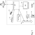
- Figure 1 is an overview block diagram illustrating an example environment in which various embodiments of a dual use remote-control device ("dual use remote") 100 may be implemented. It is to be appreciated that Figure 1 illustrates just one example of a customer premises 116 environment and that the various embodiments discussed herein are not limited to use of such systems. Customer premises 116 can include a variety of communication systems and can use a variety of communication devices, presentation devices and media including, but not limited to, satellite wireless media.
- Audio, video, and/or data service providers such as, but not limited to, television service providers, provide their customers a multitude of audio/video and/or data programming (hereafter, collectively and/or exclusively "programming"). Such programming is often provided by use of a receiving device 118 communicatively coupled to a presentation device 120 configured to receive the programming.
- Receiving device 118 interconnects to one or more communications media or sources (such as a cable head-end, satellite antenna, telephone company switch, Ethernet portal, off-air antenna, or the like) that provide the programming.
- the receiving device 118 commonly receives a plurality of programming by way of the communications media or other sources. Based upon selection by the user, the receiving device 118 processes and communicates the selected programming to the one or more presentation devices 120.
- the receiving device 118 may be interchangeably referred to as a "television converter,” “receiver,” “set-top box,” “television receiving device,” “television receiver,” “television recording device,” “satellite set-top box,” “satellite receiver,” “cable set-top box,” “cable receiver,” “media player,” and/or “television tuner.”
- the receiving device 118 may be any suitable converter device or electronic equipment that is operable to receive programming.
- the receiving device 118 may itself include user interface devices, such as buttons or switches.
- a remote-control device (“remote”) 128 is operable to control the presentation device 120 and other user devices 122.
- Examples of a presentation device 120 include, but are not limited to, a television ("TV”), a personal computer (“PC”), a sound system receiver, a digital video recorder (“DVR”), a compact disk (“CD”) device, game system, or the like. Presentation devices 120 employ a display 124, one or more speakers, and/or other output devices to communicate video and/or audio content to a user. In many implementations, one or more presentation devices 120 reside in or near a customer's premises 116 and are communicatively coupled, directly or indirectly, to the receiving device 118. Further, the receiving device 118 and the presentation device 120 may be integrated into a single device. Such a single device may have the above-described functionality of the receiving device 118 and the presentation device 120, or may even have additional functionality.
- the received program content is communicated (i.e., "uplinked") to one or more satellites 112.
- the communicated uplink signal may contain a plurality of multiplexed programs.
- the uplink signal is received by the satellite 112 and then communicated (i.e., "downlinked") from the satellite 112 in one or more directions, for example, onto a predefined portion of the planet. It is appreciated that the format of the above-described signals are adapted as necessary during the various stages of communication.
- the signal may be received by a receiving device 118.
- the receiving device 118 is a conversion device that converts, also referred to as formatting, the received signal into a signal suitable for communication to a presentation device 120 and/or a user device 122.
- the received signal communicated to the receiving device 118 is a relatively weak signal that is amplified, and processed or formatted, by the receiving device 118.
- the amplified and processed signal is then communicated from the receiving device 118 to a presentation device 120 in a suitable format, such as a television ("TV”) or the like, and/or to a user device 122.
- presentation device 120 may be any suitable device operable to present a program having video information and/or audio information.
- User device 122 may be any suitable device that is operable to receive a signal from the receiving device 118, another endpoint device, or from other devices external to the customer premises 116. Additional non-limiting examples of user device 122 include optical media recorders, such as a compact disk (“CD”) recorder, a digital versatile disc or digital video disc (“DVD”) recorder, a digital video recorder (“DVR”), or a personal video recorder (“PVR”). User device 122 may also include game devices, magnetic tape type recorders, RF transceivers, personal computers (“PCs”), and personal mobile computing devices such as cell phones or personal digital assistants (PDAs).
- CD compact disk
- DVD digital versatile disc or digital video disc
- DVR digital video recorder
- PVR personal video recorder
- User device 122 may also include game devices, magnetic tape type recorders, RF transceivers, personal computers (“PCs”), and personal mobile computing devices such as cell phones or personal digital assistants (PDAs).
- PCs personal computers
- PDAs personal digital assistant
- An interface between the receiving device 118 and a user may be provided by a hand-held remote-control device 128.
- Remote 128 typically communicates with the receiving device 118 using a suitable wireless medium, such as infrared ("IR”), radio frequency (“RF”), or the like.
- IR infrared
- RF radio frequency
- Other devices may also be communicatively coupled to the receiving device 118 so as to provide user instructions.
- Non-limiting examples include game device controllers, keyboards, pointing devices, and the like.
- the receiving device 118 may receive programming partially from, or entirely from, another source other than that described above. Other embodiments of the receiving device 118 may receive locally broadcast RF signals, or may be coupled to communication system 108 via any suitable medium. Non-limiting examples of medium communicatively coupling the receiving device 118 to communication system 108 include cable, fiber optic, or Internet media.
- Customer premises 116 may include other devices which are communicatively coupled to communication system 108 via a suitable media.
- some customer premises 116 include an optional network 136, or a networked system, to which receiving devices 118, presentation devices 120, and/or a variety of user devices 122 can be coupled, collectively referred to as endpoint devices.
- network 136 include, but are not limited to, an Ethernet, twisted pair Ethernet, an intranet, a local area network (“LAN”) system, or the like.
- One or more endpoint devices such as PCs (e.g., PC 132), data storage devices, TVs, game systems, sound system receivers, Internet connection devices, digital subscriber loop (“DSL”) devices, wireless LAN, WiFi, Worldwide Interoperability for Microwave Access (“WiMax”), or the like, are communicatively coupled to network 136 so that the plurality of endpoint devices are communicatively coupled together.
- the network 136 allows the interconnected endpoint devices, and the receiving device 118, to communicate with each other.
- some devices in the customer premises 116 may be directly connected to the network 136, such as the telephone 134 which may employ a hardwire connection or an RF signal for coupling to network 136, which may also connect to other networks or communications systems outside customer premises 116.
- the network 136 such as the telephone 134 which may employ a hardwire connection or an RF signal for coupling to network 136, which may also connect to other networks or communications systems outside customer premises 116.
- Embodiments of the dual use remote-control device (“dual use remote") 100 are operable to control the presentation device 120 and possibly also other media devices. Examples of other media devices include the receiving device 118, the presentation device 124, the user device 122, the PC 132, the remote-control device 128, and the like.
- the dual use remote 100 includes a keypad on the top side and at least one sensor on the bottom side to control cursor movement on the display 124 of the presentation device 120, and possibly also on a display of the user device 122, the PC 132, and/or other media devices.
- the dual use remote 100 may also include a partial, full or extended QWERTY keyboard on the bottom side to provide expanded text input capabilities.
- the dual use remote 100 may be configured to transmit to and receive commands from a media device. The command is typically based at least in part on a user input received via the keypad, keyboard, or sensor of the dual use remote 100.
- a user may indicate that they wish to select a particular menu item of the receiving device 118 and/or its associated presentation device 120.
- the dual use remote 100 or receiving device 118 sends the appropriate command to the receiving device 118 or presentation device 120.
- Other types of commands may be sent in addition to, or instead of, a menu selection.
- device control/function commands such as program selection, audio adjustment, picture adjustment, web browser control, window control, dialogue box control, text input, and the like, may also be sent.
- the dual use remote 100 may also receive from the media device an indication of whether use of the sensor to control a cursor is appropriate depending on what type of command is sent or what type of menu system or navigation control is currently being used or activated on the display 124 or display of another media device, thus enabling the dual use remote to determine whether to be in a mode that enables use of the sensor to control a cursor and whether to enable and/or disable other functionality of the dual use remote 100.
- the dual use remote 100 is also configured to establish a master-slave relationship between the dual use remote 100 and one or more media devices, by making the dual use remote 100 operable to control the one or more media devices.
- the dual use remote 100 can be used to identify itself as a master remote with respect to one or more other remote-control devices and/or receiving devices 118, including being operable to control a cursor and/or keyboard input on the PC 132. In this manner, the dual use remote 100 can be used to control other media devices.
- the above description of the customer premises 116, and the various devices therein, is intended as a broad, non-limiting overview of an example environment in which various embodiments of a dual use remote may be implemented.
- the customer premises 116 and the various devices therein, may contain other devices, systems and/or media not specifically described herein.
- Example embodiments described herein provide applications, tools, data structures and other support to implement a dual use remote that controls one or more media devices. Other embodiments of the described techniques may be used for other purposes, including for discovery and control of remote systems generally.
- numerous specific details are set forth, such as data formats, code sequences, and the like, in order to provide a thorough understanding of the described techniques.
- the embodiments described also can be practiced without some of the specific details described herein, or with other specific details, such as changes with respect to the ordering of the code flow, different code flows, and the like.
- the scope of the techniques and/or functions described are not limited by the particular order, selection, or decomposition of steps described with reference to any particular module, component, or routine.
- FIG. 2 is a block diagram illustrating components of an example embodiment of a dual use remote-control device 100. Note that the components of the dual use remote 100 may be implemented in software, hardware, firmware, or in some combination to achieve the capabilities described herein.
- dual use remote 100 comprises a computer memory (“memory”) 201, one or more Central Processing Units (“CPU”) 203, Input/Output "I/O" controls 204 (e.g ., keypad, QWERTY keyboard, etc.), other computer-readable media 205 (e.g ., flash memory, SIM card), network connections 206, an optical or other sensor (e.g., scroll wheel input, touch pad, touch screen, optical sensor, track ball, joystick, etc.) 207, an optional device orientation sensor 208 (e.g., a sensor using a single or multi-axis accelerometer, gyro, mercury, etc.), and a mode switch 209.
- memory memory
- CPU Central Processing Units
- I/O Input/Output
- other computer-readable media 205 e.g ., flash memory, SIM card
- network connections 206 e.g., an optical or other sensor (e.g., scroll wheel input, touch pad, touch screen, optical sensor, track ball, joystick,
- the mode switch 209 may be a manual switch, momentary switch, or a switch activated automatically by or integrated with the device orientation sensor 208 (e.g., a mercury switch, or switch activated by a multi-axis accelerometer or gyro).
- the I/O controls 204 may include the keypad and the QWERTY keyboard with reference to Figures. 3A through 3E and the optical/other sensor 207 may include the optical sensor 309 with reference to Figures 3A through 3E .
- the optical sensor and QWERTY keyboard are positioned on the opposite side of the dual use remote 100 than the keypad.
- the network connections 206 include one or more communication interfaces to various media devices, including but not limited to radio frequency transceivers, infrared transceivers, wireless Ethernet (“Wi-Fi”) interfaces, and the like.
- the one or more Central Processing Units (“CPU") 203 may be communicatively coupled to the memory 201 and the Input/Output controls 204, other computer-readable media 205, network connections 206, optical or other sensor 207, optional device orientation sensor 208, and mode switch 209 (e.g. via a communications bus) in a manner to control one or more operations of those various components.
- the dual use remote 100 may communicate with receiving device 118, presentation device 124, and possibly other media devices such as the user device 122 and PC 132 shown in Figure 1 .
- Example media devices include other remote-control devices, video recorders, audio systems, displays, personal computers, set-top boxes, and the like.
- Other types of devices include control systems for home electromechanical systems, such as a lighting system, security system, climate control system, spa/pool, and the like.
- Dual use remote-control device logic 210 and device information 211 is shown residing in memory 201. In other embodiments, some portion of the contents, some of, or all of the components of the logic 210 may be stored on the other computer-readable media 405.
- the logic 210 preferably executes on one or more CPUs 203 and manages the dual use remote 100, as described herein.
- the logic 210 may comprise or implement a system control module as executed by the on one or more CPUs 203 that are communicatively coupled to the I/O controls 204, optical/other sensor 207 and other components of the dual use remote 100.
- Other code or programs and potentially other data/information may also reside in the memory 201, and preferably execute on one or more CPUs 203.
- one or more of the components in Figure 4 may not be present in any specific implementation. For example, some embodiments may not provide other computer readable media 205.
- the logic 210 performs the core functions of the dual use remote 100, as discussed herein and also with respect to Figures 5 and 6 .
- the logic 210 may control what mode the dual use remote-control 100 is in based on the state of the device orientation sensor 208, mode switch 209 or other variables.
- the logic 210 may gather information about various media devices, such as receiving device 118, and store that information as device information 211 in order to determine a particular mode the dual use remote should be in when communicating with a particular device at a particular time depending on the information gathered.
- the logic 210 receives a mode input signal and adjusts, enables, or disables particular I/O controls 204 and/or the optical/other sensor 207 accordingly.
- the logic 210 may disable a QWERTY keyboard positioned on the same side as the optical/other sensor 207, adjust the optical/other sensor 207 to detect movement of the optical/other sensor 207 across an object (e.g., a user's lap) to wirelessly control the cursor on the display 124 (shown in Figures 1 and 4 ) based on the detected movement of the optical/other sensor 207 across the object.
- an object e.g., a user's lap
- the logic 210 may also enable a particular I/O control of the I/O controls 204 positioned on the opposite side of the dual use remote 100 to act as the selection key, which when activated (e.g., pressed), may cause a signal to be wirelessly sent to select an item displayed on the display 124 at the current position of the cursor.
- the logic 210 may enable or activate the QWERTY keyboard positioned on the same side as the optical/other sensor 207, adjust the optical/other sensor 207 to better detect movement of a finger across the optical/other sensor 207 to wirelessly control the cursor on the display 124 based on the detected movement of the finger across the optical sensor, and enable the optical/other sensor 207 or a particular I/O control of the I/O controls 204 that is positioned on the same side of the dual use remote 100 as the optical/other sensor 207 to act as the selection key, which when activated (e.g., pressed), may cause a signal to be wirelessly sent to select an item displayed on the display 124 at the current position of the cursor.
- the logic 210 also manages master-slave relationships with other media devices.
- a network of master-slave relationships known to the dual use remote 100 is stored in device information 411.
- changes to various master-slave relationships are regulated by the logic 210, and may affect the current mode into which the logic 210 may put the dual use remote 100 according to the type of device or type of user interface of the device (e.g., whether the user interface of the device uses a cursor, text input, etc.).
- remote and/or programmatic access is provided to at least some of the functionality of the dual use remote 100.
- the dual use remote 100 may provide to other media devices an application program interface ("API") that provides access to various functions of the dual use remote 100, including access to information stored by the dual use remote 100 (e.g., about other media devices), the master/slave status of the dual use remote 100, and the like.
- API application program interface
- the API may facilitate the development of third-party software, such as user interfaces, plug-ins, adapters (e.g., for integrating functions of the dual use remote 100 into various user interface applications on media devices and various desktop applications), and the like.
- a particular media device may present a customized or different user interface based upon the functionality and capabilities of the dual use remote 100.
- the logic 210 is implemented using standard programming techniques.
- the logic 210 may be implemented as a "native" executable running on the CPU 203, along with one or more static or dynamic libraries.
- the logic 210 may be implemented as instructions processed by a virtual machine that executes as some other program.
- a range of programming languages known in the art may be employed for implementing such example embodiments, including representative implementations of various programming language paradigms, including but not limited to, object-oriented (e.g ., Java, C++, C#, Visual Basic.NET, Smalltalk, and the like), functional (e.g ., ML, Lisp, Scheme, and the like), procedural (e.g., C, Pascal, Ada, Modula, and the like), scripting (e.g., Perl, Ruby, Python, JavaScript, VBScript, and the like), declarative ( e.g ., SQL, Prolog, and the like).
- object-oriented e.g ., Java, C++, C#, Visual Basic.NET, Smalltalk, and the like
- functional e.g ., ML, Lisp, Scheme, and the like
- procedural e.g., C, Pascal, Ada, Modula, and the like
- scripting e.g., Perl, Ruby, Python, JavaScript,
- the embodiments described above may also use well-known or proprietary synchronous or asynchronous client-server computing techniques.
- the various components may be implemented using more monolithic programming techniques as well, for example, as an executable running on a single CPU computer system, or alternatively decomposed using a variety of structuring techniques known in the art, including but not limited to, multiprogramming, multithreading, client-server, or peer-to-peer, running on one or more computer systems each having one or more CPUs.
- Some embodiments may execute concurrently and asynchronously, and communicate using message passing techniques. Equivalent synchronous embodiments are also supported.
- other functions could be implemented and/or performed by each component/module, and in different orders, and by different components/modules, yet still achieve the functions of the dual use remote.
- programming interfaces to the data stored as part of the device information 211 can be available by standard mechanisms such as through C, C++, C#, and Java APIs; libraries for accessing files, databases, or other data repositories; through scripting languages such as XML; or through Web servers, FTP servers, or other types of servers providing access to stored data.
- the device information 211 may be implemented as one or more database systems, file systems, or any other technique for storing such information, or any combination of the above, including implementations using distributed computing techniques.
- some or all of the components/portions of the logic 210 may be implemented or provided in other manners, such as at least partially in firmware and/or hardware, including, but not limited to one or more application-specific integrated circuits ("ASICs”), standard integrated circuits, controllers ( e.g ., by executing appropriate instructions, and including microcontrollers and/or embedded controllers), field-programmable gate arrays ("FPGAs”), complex programmable logic devices (“CPLDs”), and the like.
- ASICs application-specific integrated circuits
- controllers e.g ., by executing appropriate instructions, and including microcontrollers and/or embedded controllers
- FPGAs field-programmable gate arrays
- CPLDs complex programmable logic devices
- system components and/or data structures may also be stored as contents (e.g ., as executable or other machine-readable software instructions or structured data) on a computer-readable medium (e.g ., as a hard disk; a memory; a computer network or cellular wireless network; or a portable media article to be read by an appropriate drive or via an appropriate connection, such as a DVD or flash memory device) so as to enable or configure the computer-readable medium and/or one or more associated computing systems or devices to execute or otherwise use or provide the contents to perform at least some of the described techniques.
- a computer-readable medium e.g ., as a hard disk; a memory; a computer network or cellular wireless network; or a portable media article to be read by an appropriate drive or via an appropriate connection, such as a DVD or flash memory device
- Such computer program products may also take other forms in other embodiments. Accordingly, embodiments of this disclosure may be practiced with other computer system configurations.
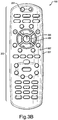
- Figures 3A-3E are diagrams illustrating top perspective, top plan, side, bottom perspective, and bottom plan views, respectively, of an example embodiment of the dual use remote-control device 100.
- Figures 3A and 3B show the dual use remote-control device housing 301, a first set of input controls 303 on a top side 302 of the dual use remote 100, and a wireless transmitter/receiver 307 (shown in Figure 3A ).
- the first set of input controls 303 includes a number of buttons positioned on the top side 302 of the dual use remote 100. The buttons may be configured to control a variety of operations for various media devices, the dual use remote 100 itself, and to navigate a variety of menus and user interfaces of the various media devices or dual use remote 100.
- These operations may include, but are not limited to channel selection, volume control, power, channel number input, fast forward, rewind, pause, and stop controls for video and audio devices, dual use remote mode switching, media device settings, on-demand services, purchase requests, and general menu and graphical user interface (GUI) navigation.
- GUI graphical user interface
- buttons shown is a power button 304 and a selection button (i.e., "OK” or "Enter” button) 305 surrounded by corresponding directional menu navigation buttons including directional button 306.
- Other input controls may be positioned on the top side 302 and may comprise all or part of the first set of input controls 303 including, but not limited to, touch screens, touch pads, track balls, optical sensors, switches, and other touch-sensitive devices.
- the housing 301 may be made of any durable plastic or polymer material, or combination of materials, suitable for enclosing and protecting the internal electronics and power source of the dual use remote 100.
- the dimensions and overall shape of the housing 301 may vary depending on the positioning and placement of the first set of input controls 303, the positioning of the particular internal electronics of the dual use remote 100 components shown in Figure 2 , and any modifications for ease and comfort of use of the dual use remote 100.
- Figures 3C , 3D and 3E are diagrams illustrating side, bottom perspective, and bottom plan views, respectively, of the example embodiment of the dual use remote-control device 100.
- Figures 3C , 3D and 3E additionally show a second set of input controls 308 positioned on the bottom side 311 of the dual use remote 100 opposite the top side 302.
- Figure 3C also shows an example thickness 312 of the dual use remote, which may vary depending on the positioning and type of internal electronics of the dual use remote 100, but in one example embodiment, is approximately 25 mm.
- the first set of input controls 303 and second set of input controls 308 may include buttons that extend slightly above the planar surface of the respective top side 302 and bottom side 311, respectively, on which they are positioned.
- buttons of the second set of input controls 308 may be made of, painted, or finished with a material that enables the buttons to slide smoothly across an object.
- an object may be a table, couch, chair, or a user's lap.
- the dual use remote 100 may be in a mode to control a cursor by sliding the optical sensor 309 (shown in Figures 3D and 3E ), also located on the bottom side 308 of the dual use remote 100, across the object.
- Such material may include a smooth, hard plastic or hard rubber, or other suitable material instead of a soft rubber, rubberized or soft plastic material.
- the dual use remote 100 When the dual use remote 100 is in a mode to control the cursor by sliding the optical sensor 309 (shown in Figures 3D and 3E ) located on the bottom side 311 of the dual use remote 100 across an object, there may be a particular input control of the first set of input controls 303 located on the top side 303 that is activated or enabled to be used as a selection control to select an item at the current position of the cursor on the display.
- this particular input control used as the selection control when the dual use remote is being used in such a mode may be the select button 305.
- other input controls of the first set of input controls on the top side 302, or other input controls located on a side of the dual use remote 100 may also or alternatively be used as a select control or select button.
- Figure 3D shows a sensor 309 (in the present example, an optical sensor) and a QWERTY keyboard 310 included in the second set of input controls 308 positioned on the bottom side 311 of the dual use remote 100.
- the optical sensor 309 may be any optical sensor suitable for detecting finger movement across the optical sensor 309 and movement of the optical sensor 309 across an object such as a table, couch, chair or user's lap.
- optical sensors are available from Avago Technologies, having a headquarters in San Jose, California.
- the optical sensor 309 may be operable and configured to enable wireless control of a cursor on a display (e.g., a television monitor) based on the detected movement of a finger across the optical sensor 309 or based on the detected movement of the optical sensor 309 across the object.
- the optical sensor 309 may be configured to send a signal to select a particular item on a display at a current location of the cursor on the display when a user pushes on the optical sensor 309, thus activating a button mechanism to which the optical sensor 309 may be coupled in order to activate the selection signal.
- the optical sensor 309 may be flush or slightly recessed from the planar surface of the back side 311 of the dual use remote 100. However, other configurations and locations of the optical sensor 309 may be used such that the distance between the optical sensor 309 and an object over which it is being passed is sufficient for the optical sensor 309 to detect movement of the optical sensor 309 over the object.
- the optical sensor 309 may be positioned anywhere the bottom side 311, end or side of the dual use remote housing 301. However, if the QWERTY keyboard 310 is also included in the second set of input controls 308, the optical sensor 311 may be positioned in an area on the bottom side 311, end or side of the dual use remote housing 301 that does not substantially interfere with use of the QWERTY keyboard 310. Also, the optical sensor 309 may be positioned in the general area of the top end of the dual use remote 100 as shown in Figure 3 , the top end being that which faces upward or away from the user while the dual use remote 100 is oriented by a user to read button labels on the top side 302 of the dual use remote 100.
- the optical sensor 309 is shown positioned on the righthand side of the QWERTY keyboard 310 in Figures 3D and 3E . However, the optical sensor 309 may alternatively be positioned on the left-hand side of the QWERTY keyboard 310, as may be preferable for left-handed users.
- Figures 3D and 3E show a full QWERTY keyboard 310 positioned on the bottom side 311.
- the QWERTY keyboard 310 is configured and operable to allow a user to enter or communicate text input to the dual use remote 100 and/or various media devices with which the dual use remote 100 may be in communication while also use the optical sensor 309 to control movement of a cursor or other graphical object on a display of a device with which the dual use remote 100 is in communication.
- Included in the QWERTY keyboard 310 may be individual buttons corresponding to each letter of the English alphabet and a space bar.
- buttons or keys of the QWERTY keyboard 310 may include, but are not limited to: enter, shift, backspace, numbers, tab, control, alt, caps lock, special symbols, punctuation marks, direction keys, function keys, customized keys, 10-key keypad, number lock, etc. Also, other keys of the QWERTY keyboard may correspond to characters of other languages than English. Also included on the top, bottom, sides or ends of the dual use remote 100 may be various other controls and/or switches (not shown) to control operations and modes of the dual use remote 100 or operations of other media devices with which the dual use remote 100 may be in communication.
- Figure 4 is a block diagram illustrating an example embodiment of a dual use remote-control device 100 in communication with a presentation device 120.
- Figure 4 shows an example dual use remote 100 operating in customer premises 116.
- the customer premises116 includes a dual use remote 100, receiving device 118, and presentation device 120 having a display 124.
- On the display 124 are shown example user interfaces and applications.
- an example TV/Satellite menu 401, a cursor 402, and an example web browser 403 are shown.
- the TV/Satellite menu 401 may have various controls and menus with which the cursor 402 interacts to select particular menu items 404.
- shown is a slider bar 405, to enable a user to scroll through particular example menu items 404 (four of which are shown).
- the web browser 407 may include various menu items and controls that interact with the same cursor 402 and also receive input from the QWERTY keyboard 310 of the dual use remote 100 through the receiving device 118. For example, shown are window controls 407 to minimize, maximize or close the GUI window of the web browser 403 when selected using the cursor 402. Also, text may be input at the address bar 406 of the web browser 403 using the QWERTY keyboard 310 of the dual use remote 100. For example, a user may enter text into a web browser 403 being displayed on a user's television using the QWERTY keyboard 310 and use the optical sensor 309 to control a cursor and select items on a particular web site displayed within the web browser 403.
- menus, interfaces and applications may be displayed and controlled using the optical sensor 309 to control movement of the cursor 402 and/or using the QWERTY keyboard 310 to enter text or other input into the various menus, interfaces and applications in communication with the presentation device 120 and/or the receiving device 118.
- Examples of such other menus, interfaces and applications include, but are not limited to, menus, interfaces and applications of: televisions, satellite and cable receivers, DVD players, game consoles, computers, and computer networks.
- digital video or audio recorders or players include digital video or audio recorders or players, analog video or audio recorders or players, stereo equipment, home appliances, mobile devices, MP3 players, cellular phones, home entertainment systems, home theater systems, smart home systems, home electromechanical systems, such as a lighting system, security system, climate control system, spa/pool, and the like, or other media devices, etc.
- receiving device 118 is a set-top box coupled to presentation device 120.
- the dual use remote 100 may wirelessly communicate and receive information to and from the receiving device 118 and also possibly other devices (not shown) on the customer premises 116. This information communicated to the receiving device 118 is communicated to presentation device 120 in order to provide various input to control the presentation device or other devices or applications in communication with the presentation device and/or receiving device 118.
- the receiving device 118 and presentation device 120 may be integrated into one device.
- the dual use remote 100 may operate in a number of different modes, each mode corresponding to a particular physical orientation, switch position, current menu or interface selected, current device being communicated with, or a combination of the foregoing items. For example, when the dual use remote 100 is oriented such that the side having the optical sensor 309 is facing upward, the device may change modes causing the settings of the optical sensor 309 to be adjusted to better detect movement of a finger across the optical sensor 309 and/or causing the first set of input controls on the opposite side of the dual use remote 100 to be disabled.
- Other automatic adjustments may include, transposing, when the dual use remote 100 changes between modes (e.g., as indicated by a mode input signal), at least a portion of a coordinate system used to translate movement detected by the optical sensor to movement of the cursor 402. For example, what were previously up and down motions as detected by the optical sensor 309 in one mode may be transposed to left and right, respectively, and vice versa.
- the QWERTY keyboard 310 may also be disabled when facing downward such that the keys on the keyboard 310 are not inadvertently pressed when moving the dual use remote 100 over objects such as tables, couches, chars, a user's lap, etc.
- the QWERTY keyboard 310 may again be automatically enabled when facing upward.
- the sensitivity of the optical sensor 309 and/or a scale used in translating a distance of movement detected by the optical sensor 309 to movement of the cursor 402, and other calibrations may be automatically adjusted depending on what mode the dual use remote 100 is in. For example, when the dual use remote 100 is oriented such that the side having the optical sensor 309 is facing upward, a scale is adjusted such that a movement by the optical sensor 309 of a certain distance results in larger movement of the cursor 402 than a movement detected of the same distance when the dual use remote 100 is oriented such that the side having the optical sensor 309 is facing downward. This is due to the overall larger areas of movement detected by the optical sensor 309 when moving the optical sensor 309 over a table or user's lap than when moving a finger over the optical sensor 309 to control cursor movement in a different mode.
- the current menu or device with which the dual use remote 100 is communicating may also affect the particular mode in which the dual use remote 100 is operating. This may be enabled by two-way communication between the dual use remote 100 and the particular device (e.g., presentation device 120 and/or receiving device 118). For example, when a user interface or menu system that accepts text input and/or uses the cursor 402 is entered, activated or displayed on the display 124, this may be communicated to the dual use remote 100 such that the dual use remote 100 may change modes, if needed, to activate and/or adjust the optical sensor 309, enable the QWERTY keyboard 310, and/or disable other keys or input controls as appropriate.
- a user opens a web browser 403 on their television or starts communicating with their computer using the dual use remote 100, this may result in a mode being entered by dual use remote 100 causing the QWERTY keyboard to be activated.
- the optical sensor is also activated and adjusted to better detect finger movement.
- the first set of input controls on the opposite side of the dual use remote 100 from the QWERTY keyboard and optical sensor 309 may also be temporarily disabled or deactivated while in such a mode.
- various types of access controls may be employed.
- one or more of the functions or modes of the dual use remote 100 may be password protected, such that the user must provide a password or other identifier (e.g., a PIN, biometric identifier, etc.) to access the protected functions or modes, or content.
- a password or other identifier e.g., a PIN, biometric identifier, etc.
- Figure 5 is a flow diagram of an example dual use remote-control process provided by an example embodiment.
- Figure 5 illustrates process 500 that may be implemented, for example, by the logic 210 executing on the dual use remote 100, described with respect to Figure 2 .
- the process 500 starts at 501 wherein the process waits for a mode input signal and then at 502 the process receives the mode input signal.
- the mode input signal may be a signal automatically received based on output of an orientation sensor indicating a physical orientation of the dual use remote, a manual switch on the dual use remote, information communicated to the dual use remote from a device it is controlling or with which it is communicating, or a combination of such items.
- the process deactivates and/or activates particular input controls based on mode the input signal. For example, the process may activate or deactivate the optical sensor or keyboard or other input controls according to the particular mode indicated by the mode input signal.
- the process also adjusts the optical sensor based on the received mode input signal. For example, this adjustment may include sensitivity, scale and coordinate systems used by the optical sensor as well as other adjustments.
- the process sends a signal to select the item at the current cursor position.
- the dual use remote may have an input control such as a button that the user may press when the user desires to select an item at the current location of the cursor being controlled by the optical sensor. This, however, occurs when the dual use remote is in a mode in which the optical sensor is currently active.
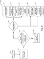
- Figure 6 is a flow diagram of an example dual use remote-control process including more detailed operations for switching modes provided by an example embodiment.
- the process 600 starts at 601 wherein the process waits for a mode input signal and then at 602 the process receives the mode input signal.
- the mode input signal may be a signal automatically received based on output of an orientation sensor indicating a physical orientation of the dual use remote, a manual switch on the dual use remote, information communicated to the dual use remote from a device it is controlling or with which it is communicating, or a combination of such items.
- the process determines whether the mode input signal indicates the user interface currently selected to be displayed uses a cursor.
- the optical sensor is deactivated if it is currently active and the process returns to 602.
- the process determines whether the optical sensor is facing up. For example, this may be determined by an indication by the input signal itself or other signals indicative of whether the optical sensor is facing up (e.g., an orientation sensor, manual switch, etc.).
- the QWERTY keyboard on the same side of the dual use remote as the optical sensor is activated or enabled if not already activated.
- the keys on the opposite side of device from the optical sensor are optionally deactivated or disabled. This option may be user selectable when initially configuring the dual use remote.
- the optical sensor may be adjusted to better detect and translate finger movement to cursor movement as described above.
- the keyboard on the same side of the dual use remote as the optical sensor is deactivated or disabled. This option, among others, may also be user selectable during initial configuration of the dual use remote.
- the optical sensor is also adjusted to better detect and translate movement of the optical sensor over an object to cursor movement on the display as described above.
- Some embodiments perform one or more operations/aspects in addition to the ones described with respect to process 500 and process 600.
- the process 500 and process 600 or parts thereof may automatically execute upon the occurrence of other events, such as a request received from a media device in which the dual use remote is in communication.
Landscapes
- Engineering & Computer Science (AREA)
- General Engineering & Computer Science (AREA)
- Theoretical Computer Science (AREA)
- Human Computer Interaction (AREA)
- Physics & Mathematics (AREA)
- General Physics & Mathematics (AREA)
- Multimedia (AREA)
- Signal Processing (AREA)
- Details Of Television Systems (AREA)
- User Interface Of Digital Computer (AREA)
- Selective Calling Equipment (AREA)
- Input From Keyboards Or The Like (AREA)
Claims (14)
- Fernsteuerungsvorrichtung (100) zum Steuern eines Mediengeräts (118) mit einer dazugehörigen Anzeige (120), wobei die Fernsteuerungsvorrichtung (100) aufweist:ein Fernsteuerungsvorrichtungsgehäuse (301) mit einer ersten Seite (302) und einer zweiten Seite (311), wobei die erste Seite (302) der zweiten Seite (311) entgegengesetzt ist;ein Systemsteuerungsmodul in dem Gehäuse;einen ersten Satz von Eingabebedienelementen (303), die auf einer ersten Seite (302) des Gehäuses kommunikativ mit dem Systemsteuermodul verbunden positioniert sind;einen zweiten Satz von Eingabebedienelementen (308), die auf einer zweiten Seite (311) des Gehäuses und kommunikativ mit dem Systemsteuermodul verbunden positioniert sind, wobei der zweite Satz von Eingabebedienelementen mindestens einen optischen Sensor (309) aufweist, der konfiguriert ist, um drahtlos eine Bewegung eines Cursors auf einer Benutzeroberfläche zu steuern, die durch das Mediengerät auf der Anzeige (120) angezeigt wird;das Systemsteuerungsmodul, das konfiguriert ist, um ein Moduseingabesignal zu empfangen, das an der Fernsteuerungsvorrichtung intern erzeugt wird, undum die Fernsteuerungsvorrichtung zwischen einem ersten Betriebsmodus und einem zweiten Betriebsmodus gemäß dem Moduseingabesignal umzuschalten,wobei der optische Sensor (309) in dem ersten Modus konfiguriert ist, um eine Bewegung des Cursors auf der Anzeige drahtlos zu steuern, indem eine Gleitbewegung des optischen Sensors (309) über eine Gleitfläche eines Objekts erkannt wird, und das Systemsteuerungsmodul konfiguriert ist, um ein Element in der Benutzeroberfläche auszuwählen, das auf der Anzeige an der aktuellen Position des Cursors angezeigt wird, wenn ein bestimmtes Eingabebedienelement des ersten Satzes von Eingabebedienelementen (303) aktiviert wird,wobei der optische Sensor (309) in dem zweiten Modus konfiguriert ist, eine Bewegung des Cursors auf der Anzeige drahtlos durch Erkennen einer Bewegung eines Fingers über den optischen Sensor (309) zu steuern, und das Systemsteuerungsmodul konfiguriert ist, um ein Element in der Benutzeroberfläche auszuwählen, das auf der Anzeige an einer aktuellen Position des Cursors angezeigt wird, wenn ein Eingabebedienelement des zweiten Satzes von Eingabebedienelementen (308) aktiviert wird, und wobei der zweite Satz von Eingabebedienelementen (308) ferner eine QWERTY-Tastatur (310) aufweist,dadurch gekennzeichnet, dass die Fernsteuerungsvorrichtung mit Netzwerkverbindungseinheiten (206) versehen ist, die das Herstellen einer Zweiwegekommunikation mit dem gesteuerten Mediengerät (118) ermöglichen;das Moduseingabesignal zumindest teilweise auf einer durch die Fernsteuerungsvorrichtung (100) von dem Mediengerät (118) empfangenen Angabe beruht, welcher Typ von Menüsystem oder Navigationssteuerung aktuell verwendet oder auf der Anzeige (120) des Mediengeräts (118) aktiviert wird;der Empfang einer Angabe, dass die Benutzeroberfläche, auf welcher der Cursor angezeigt wird, Texteingabe akzeptiert, das Systemsteuerungsmodul veranlasst, die Fernsteuerungsvorrichtung auf den zweiten Modus umzuschalten, wobeidie QWERTY-Tastatur (310) aktiviert wird;der erste Satz von Eingabebedienelementen (303) deaktiviert wird;der optische Sensor (309) konfiguriert ist, um eine Bewegung des Cursors auf der Anzeige durch Erkennen einer Bewegung eines Fingers über den optischen Sensor (309) drahtlos zu steuern.
- Fernsteuerungsvorrichtung nach Anspruch 1, wobei das Eingabebedienelement des zweiten Satzes von Eingabebedienelementen (308), das zum Auswählen eines Elements gedrückt wird, das an einer aktuellen Position des Cursors auf der Anzeige angezeigt wird, der optische Sensor (309) ist.
- Fernsteuerungsvorrichtung nach Anspruch 1 oder Anspruch 2, wobei der erste Satz von Eingabebedienelementen (303) Schaltflächen sind und Fernsehkanal-Auswahlschaltflächen, eine Einschalttaste und eine Auswahltaste aufweisen.
- Fernsteuerungsvorrichtung nach Anspruch 1 bis 3, wobei das Moduseingabesignal konfiguriert ist, um die Fernsteuerungsvorrichtung automatisch bei einer bestimmten Bewegung der Fernsteuerungsvorrichtung (100) umzuschalten.
- Fernsteuerungsvorrichtung nach Anspruch 4, wobei das Moduseingabesignal konfiguriert ist, um die Fernsteuerungsvorrichtung in den zweiten Modus umzuschalten, wenn erkannt wird, dass die zweite Seite nach oben gerichtet ist, wie durch die bestimmte Bewegung der Fernsteuerungsvorrichtung angegeben.
- Fernsteuerungsvorrichtung nach einem der Ansprüche 1 bis 5, wobei das Systemsteuerungsmodul konfiguriert ist, um den zweiten Satz von Eingabebedienelementen (308) mit Ausnahme des optischen Sensors (309) automatisch zu deaktivieren, wenn erkannt wird, dass die zweite Seite nach unten gerichtet ist.
- Fernsteuerungsvorrichtung nach einem der Ansprüche 1 bis 6, wobei das Moduseingabesignal konfiguriert ist, um die Verwendung des optischen Sensors zu aktivieren oder deaktivieren, um den Cursor zumindest teilweise auf Grundlage einer Angabe zu steuern, die von der Fernsteuerungsvorrichtung von dem Mediengerät empfangen wird, dass die aktuell zum Anzeigen auf der Anzeige ausgewählte Benutzeroberfläche den Cursor verwendet, um die Fernsteuerungsvorrichtung damit zu veranlassen, den optischen Sensor zu deaktivieren, wenn der Cursor nicht verwendet wird.
- Fernsteuerungsvorrichtung nach einem der Ansprüche 1 bis 7, wobei das Systemsteuerungsmodul konfiguriert ist, um zumindest einen Abschnitt eines Koordinatensystems umzusetzen, wenn die Fernsteuerungsvorrichtung (100) zwischen dem ersten und dem zweiten Modus wechselt, wobei das Koordinatensystem verwendet wird, um eine Bewegung, die durch den optischen Sensor erkannt wird, in eine Bewegung des Cursors zu übersetzen.
- Verfahren zum Steuern des Betriebs einer Fernsteuerungsvorrichtung (100), die konfiguriert ist, um ein Mediengerät (118) mit einer zugehörigen Anzeige (120) zu steuern, wobei die Fernsteuerungsvorrichtung ein Systemsteuerungsmodul, einen ersten Satz von Eingabebedienelementen (303), die auf einer ersten Seite der Fernsteuerungsvorrichtung positioniert sind, und einen zweiten Satz von Eingabebedienelementen (308) mit mindestens einem optischen Sensor (309) hat, die auf einer zweiten Seite der Fernsteuerungsvorrichtung positioniert sind, die der ersten Seite entgegengesetzt ist, wobei der optische Sensor angeordnet ist, um die Position eines Cursors in einer Benutzeroberfläche zu steuern, die von dem Mediengerät auf der Anzeige angezeigt wird, und wobei der zweite Satz von Eingabebedienelementen (308) ferner eine QWERTY-Tastatur aufweist;
wobei das Verfahren aufweist:nach Empfang eines Moduseingabesignals durch das Systemsteuerungsmodul der Fernsteuerungsvorrichtung (100), das an der Fernsteuerungsvorrichtung intern erzeugt wird und angibt, dass die Fernsteuerungsvorrichtung (100) auf einen ersten Betriebsmodus umschalten soll, Konfigurieren des optischen Sensors (309), um eine Gleitbewegung des optischen Sensors über eine Gleitfläche eines Objekts besser zu erkennen, um einen Cursor auf der Anzeige auf Grundlage der erkannten Bewegung des optischen Sensors über das Objekt drahtlos zu steuern und drahtlos ein Signal zu senden, um ein Element auf der Benutzeroberfläche, das auf der Anzeige (120) an einer aktuellen Position des Cursors angezeigt wird, auszuwählen, wenn ein Eingabebedienelement des ersten Satzes von Eingabebedienelementen (308) gedrückt wird, wenn sich die Fernsteuerungsvorrichtung im ersten Modus befindet;nach Empfang des Moduseingabesignals durch das Systemsteuerungsmodul der Fernsteuerungsvorrichtung (100), das angibt, dass die Fernsteuerungsvorrichtung auf einen zweiten Betriebsmodus umschalten soll,Konfigurieren des optischen Sensors (309) der Fernsteuerungsvorrichtung, um eine Bewegung eines Fingers über den optischen Sensor besser zu erkennen, um den Cursor auf der Anzeige auf Grundlage der erkannten Bewegung des Fingers über den optischen Sensor drahtlos zu steuern unddrahtlos ein Signal zu senden, um ein Element auf der Benutzeroberfläche, das auf der Anzeige an einer aktuellen Position des Cursors angezeigt wird, auszuwählen, wenn ein bestimmtes Eingabebedienelement des zweiten Satzes von Eingabebedienelementen gedrückt wird, wenn sich die Fernsteuerungsvorrichtung im zweiten Modus befindet;dadurch gekennzeichnet, dassdie Fernsteuerungsvorrichtung mit Netzwerkverbindungseinheiten (206) versehen ist, die das Herstellen einer Zweiwegekommunikation mit dem gesteuerten Mediengerät (118) ermöglichen; das Moduseingabesignal zumindest teilweise auf einer durch die Fernsteuerungsvorrichtung (100) von dem Mediengerät (118) empfangenen Angabe beruht, welcher Typ von Menüsystem oder Navigationssteuerung aktuell verwendet oder auf der Anzeige (120) des Mediengeräts (118) aktiviert wird;nach Empfang einer Angabe, dass die Benutzeroberfläche, auf welcher der Cursor angezeigt wird, Texteingabe akzeptiert, das Systemsteuerungsmodul die Fernsteuerungsvorrichtung auf den zweiten Modus umschaltet, indemdie QWERTY-Tastatur (310) aktiviert wird,wodurch der erste Satz von Eingabebedienelementen (303) deaktiviert wird; undder optische Sensor (309) der Fernsteuerungsvorrichtung konfiguriert wird, den Cursor auf der Anzeige auf Grundlage der erkannten Bewegung des Fingers über den optischen Sensor drahtlos zu steuern. - Fernsteuerungsvorrichtung nach Anspruch 9, ferner aufweisend ein automatisches Deaktivieren oder Reaktivieren der Verwendung des optischen Sensors, um den Cursor abhängig von dem Moduseingabesignal zu steuern, das zusätzlich zumindest teilweise auf einer Angabe beruht, die von der Fernsteuerungsvorrichtung von dem Mediengerät empfangen wird, dass die Benutzeroberfläche den Cursor verwendet, um die Fernsteuerungsvorrichtung damit zu veranlassen, den optischen Sensor zu deaktivieren, wenn der Cursor nicht verwendet wird.
- Verfahren nach Anspruch 9 oder Anspruch 10, ferner aufweisend ein automatisches Erzeugen des Moduseingabesignals mit einem bestimmten Wert, der auf einer Bewegung der Fernsteuerungsvorrichtung beruht, die angibt, ob die obere Seite oder die untere Seite aktuell nach oben gerichtet ist.
- Verfahren nach einem der Ansprüche 9 bis 11, ferner aufweisend ein automatisches Deaktivieren des zweiten Satzes von Eingabebedienelementen mit Ausnahme des optischen Sensors, wenn erkannt wird, dass die untere Seite nach unten gerichtet ist, wie durch das empfangene Moduseingabesignal angegeben.
- Verfahren nach einem der Ansprüche 9 bis 12, ferner aufweisend, wenn die Fernsteuerungsvorrichtung zwischen dem ersten und dem zweiten Modus wechselt, wie durch das Moduseingabesignal angegeben, ein Umsetzen von mindestens einem Abschnitt eines Koordinatensystems, das zum Übersetzen der Bewegung, die durch den optischen Sensor erkannt wird, in eine Bewegung des Cursors verwendet wird.
- Verfahren nach einem der Ansprüche 9 bis 13, wobei das Konfigurieren des optischen Sensors zum besseren Erkennen einer Bewegung eines Fingers über den optischen Sensor und ein Konfigurieren des optischen Sensors der Fernsteuerungsvorrichtung zum besseren Erkennen einer Gleitbewegung des optischen Sensors über die Gleitfläche eines Objekte ein Anpassen von einem oder mehrerem aufweist von: einer Empfindlichkeit des optischen Sensors und eines Maßstabs, der beim Übersetzen eines von dem optischen Sensor erkannten Bewegungsabstands in eine Bewegung des Cursors verwendet wird.
Applications Claiming Priority (2)
| Application Number | Priority Date | Filing Date | Title |
|---|---|---|---|
| US12/835,403 US9542007B2 (en) | 2010-07-13 | 2010-07-13 | Systems and methods for dual use remote-control devices |
| PCT/US2011/043870 WO2012009444A2 (en) | 2010-07-13 | 2011-07-13 | Systems and methods for dual use remote-control devices |
Publications (3)
| Publication Number | Publication Date |
|---|---|
| EP2594084A2 EP2594084A2 (de) | 2013-05-22 |
| EP2594084A4 EP2594084A4 (de) | 2014-01-29 |
| EP2594084B1 true EP2594084B1 (de) | 2018-08-29 |
Family
ID=45466554
Family Applications (1)
| Application Number | Title | Priority Date | Filing Date |
|---|---|---|---|
| EP11807459.0A Active EP2594084B1 (de) | 2010-07-13 | 2011-07-13 | Systeme und verfahren für zweifach verwendbare fernsteuerungsvorrichtungen |
Country Status (6)
| Country | Link |
|---|---|
| US (2) | US9542007B2 (de) |
| EP (1) | EP2594084B1 (de) |
| CN (1) | CN102986244B (de) |
| CA (1) | CA2804886C (de) |
| MX (1) | MX342452B (de) |
| WO (1) | WO2012009444A2 (de) |
Families Citing this family (19)
| Publication number | Priority date | Publication date | Assignee | Title |
|---|---|---|---|---|
| US8578081B1 (en) | 2007-07-25 | 2013-11-05 | Robert Louis Fils | Docking station for an electronic device |
| US9030406B2 (en) * | 2010-09-17 | 2015-05-12 | Viaclix, Inc. | Remote control functionality including information from motion sensors |
| US8635306B2 (en) * | 2010-09-21 | 2014-01-21 | Sony Corporation | System and method for display device character input |
| KR101786577B1 (ko) * | 2010-10-19 | 2017-11-15 | 삼성전자주식회사 | 양방향 리모콘 제어 방법 및 이를 수행하는 양방향 리모콘 |
| US8698745B2 (en) * | 2011-05-20 | 2014-04-15 | Echostar Technologies L.L.C. | Configuring the functionality of control elements of a control device based on orientation |
| US8842072B2 (en) * | 2012-01-05 | 2014-09-23 | Pareto Mill Llc | Keypad mouse computer peripheral device |
| KR20130103934A (ko) * | 2012-03-12 | 2013-09-25 | 삼성전자주식회사 | 디스플레이장치 및 그 제어방법 |
| SG11201408663PA (en) | 2012-06-26 | 2015-02-27 | Vodoke Asia Pacific Ltd | A remote controller |
| KR101755625B1 (ko) | 2013-01-07 | 2017-07-07 | 삼성전자주식회사 | 디스플레이 장치, 그의 ui 표시 방법 및 컴퓨터 판독가능 기록매체 |
| US9740304B2 (en) * | 2013-03-13 | 2017-08-22 | Google Inc. | Systems, methods, and media for providing an enhanced remote control having multiple modes |
| US20160175189A1 (en) * | 2013-04-08 | 2016-06-23 | Robert Louis Fils | Method, system and apparatus for communicating with an electronic device and a stereo housing |
| CN103475926A (zh) * | 2013-09-13 | 2013-12-25 | 深圳好视网络科技有限公司 | 基于机顶盒设备的输入法实现方法及控制系统 |
| CN107037899A (zh) * | 2015-07-16 | 2017-08-11 | 鸿富锦精密工业(深圳)有限公司 | 触控薄膜及应用触控薄膜的触控模组 |
| USD805517S1 (en) * | 2016-05-18 | 2017-12-19 | Shenzhen Sungi Technology Co., Ltd. | Keyboard |
| EP3475932A4 (de) | 2017-06-21 | 2019-05-29 | SZ DJI Technology Co., Ltd. | Verfahren und vorrichtungen im zusammenhang mit umwandelbaren fernbedienungen |
| CN108040275B (zh) * | 2017-12-29 | 2020-08-21 | 福州福大海矽微电子有限公司 | 一种遥控器操作网页浏览器的方法及终端 |
| JP7309435B2 (ja) * | 2019-04-26 | 2023-07-18 | キヤノン株式会社 | 電子機器、電子機器の制御方法、プログラム、記録媒体 |
| US11647246B1 (en) * | 2022-04-27 | 2023-05-09 | Dish Network L.L.C. | Remote control with transmitters |
| US12425460B2 (en) * | 2023-02-23 | 2025-09-23 | Merlyn Mind, Inc. | Content transfer among remote-control units and integrated output devices |
Family Cites Families (58)
| Publication number | Priority date | Publication date | Assignee | Title |
|---|---|---|---|---|
| USD331760S (en) | 1990-05-29 | 1992-12-15 | Thomson Consumer Electronics, Inc. | Remote control |
| US5063289A (en) * | 1990-10-09 | 1991-11-05 | Lexmark International, Inc. | Combined mouse and trackball |
| USD342259S (en) | 1992-07-02 | 1993-12-14 | Universal Electronics | Universal remote control |
| USD366044S (en) | 1994-03-16 | 1996-01-09 | Matsushita Electric Industrial Co., Ltd. | Remote controller for television receiver |
| USD366043S (en) | 1994-03-16 | 1996-01-09 | Matsushita Electric Industrial Co., Ltd. | Remote controller for television receiver |
| USD361058S (en) | 1994-04-28 | 1995-08-08 | Harmonic Design, Inc. | Remote control unit for operating window blinds |
| US5457479A (en) * | 1994-06-13 | 1995-10-10 | Primax Electronics Ltd. | Apparatus having dual modes for controlling cursor on display screen |
| US5726684A (en) * | 1996-07-26 | 1998-03-10 | Ncr Corporation | Detachable convertible mouse-trackball pointing device for use with a computer |
| USD389838S (en) | 1996-12-12 | 1998-01-27 | DIBA, Inc. | Handheld remote control device |
| US6448977B1 (en) * | 1997-11-14 | 2002-09-10 | Immersion Corporation | Textures and other spatial sensations for a relative haptic interface device |
| US8020095B2 (en) * | 1997-11-14 | 2011-09-13 | Immersion Corporation | Force feedback system including multi-tasking graphical host environment |
| KR100243159B1 (ko) * | 1997-12-01 | 2000-02-01 | 윤종용 | 무선 마우스 일체형 리모트콘트롤러 |
| US6256011B1 (en) * | 1997-12-03 | 2001-07-03 | Immersion Corporation | Multi-function control device with force feedback |
| US6094156A (en) | 1998-04-24 | 2000-07-25 | Henty; David L. | Handheld remote control system with keyboard |
| USD418820S (en) | 1998-08-14 | 2000-01-11 | Sony Corporation | Remote controller |
| US20030016417A1 (en) * | 2001-07-17 | 2003-01-23 | Cruise Lee | Wireless pointing and remote-controlling device for briefing |
| US6762751B2 (en) * | 2001-12-17 | 2004-07-13 | Behavior Tech Computer Corporation | Optical pointing device |
| USD477590S1 (en) | 2002-01-18 | 2003-07-22 | Lg Electronics Inc. | Remote-control for projector |
| US20030184520A1 (en) * | 2002-03-28 | 2003-10-02 | Patrick Wei | Mouse with optical buttons |
| CN1206585C (zh) * | 2003-01-06 | 2005-06-15 | 致伸科技股份有限公司 | 两用型光学式鼠标 |
| UY3420Q (es) | 2003-10-06 | 2004-03-31 | Sony Computer Entertainment Inc | Control remoto |
| US7209116B2 (en) * | 2003-10-08 | 2007-04-24 | Universal Electronics Inc. | Control device having integrated mouse and remote control capabilities |
| US20050128180A1 (en) * | 2003-12-10 | 2005-06-16 | Chong-Min Wang | Portable presentation operating device |
| US20050146497A1 (en) * | 2003-12-31 | 2005-07-07 | Clapper Edward O. | Peripheral device including features of a mouse and of a remote control unit |
| US20050162569A1 (en) * | 2004-01-06 | 2005-07-28 | Sharp Laboratories Of America, Inc. | Television remote control system and method with alphanumeric input |
| USD571790S1 (en) | 2004-04-01 | 2008-06-24 | Funai Electric Co., Ltd. | Remote controller |
| US20070132733A1 (en) * | 2004-06-08 | 2007-06-14 | Pranil Ram | Computer Apparatus with added functionality |
| US20060012567A1 (en) * | 2004-07-13 | 2006-01-19 | Todd Sicklinger | Minature optical mouse and stylus |
| USD584718S1 (en) | 2004-11-30 | 2009-01-13 | Vkr Holding A/S | Remote control |
| US20150193023A1 (en) * | 2005-01-05 | 2015-07-09 | Swiftpoint Limited | Devices for use with computers |
| US20060152491A1 (en) * | 2005-01-10 | 2006-07-13 | Yankee Technology Co., Ltd. | Mouse and remote control integration control method and device |
| CN101576780A (zh) * | 2005-01-30 | 2009-11-11 | 史翠克有限公司 | 电脑鼠标周边装置 |
| TWI256785B (en) * | 2005-02-25 | 2006-06-11 | He-Lung Lu | Remote control method for wireless mouse |
| USD532777S1 (en) | 2005-03-10 | 2006-11-28 | Hon Hai Precision Ind. Co., Ltd. | Remote controller |
| US20060232550A1 (en) * | 2005-04-15 | 2006-10-19 | Buckner Nathan C | Integrated mouse in remote control |
| US8022928B2 (en) * | 2005-08-22 | 2011-09-20 | Qinzhong Ye | Free-space pointing and handwriting |
| USD549666S1 (en) | 2005-10-21 | 2007-08-28 | Koninklijke Philips Electronics N.V. | Remote control unit |
| USD543971S1 (en) | 2006-02-09 | 2007-06-05 | Koninklijke Philips Electronics N.V. | Remote control |
| US20070268250A1 (en) * | 2006-02-27 | 2007-11-22 | Nubron Inc. | Remote input device for computers |
| US20090201248A1 (en) * | 2006-07-05 | 2009-08-13 | Radu Negulescu | Device and method for providing electronic input |
| USD551659S1 (en) | 2006-08-18 | 2007-09-25 | Amtran Technology Co., Ltd. | Remote control |
| AU313676S (en) | 2006-09-21 | 2007-04-17 | Sony Computer Entertainment Inc | Remote controller for electronic device |
| USD577721S1 (en) | 2006-12-15 | 2008-09-30 | Microsoft Corporation | Wireless receiver |
| USD585052S1 (en) | 2006-12-29 | 2009-01-20 | Barron Sa | Combined station and remote control |
| US9176598B2 (en) * | 2007-05-08 | 2015-11-03 | Thinkoptics, Inc. | Free-space multi-dimensional absolute pointer with improved performance |
| US20080284735A1 (en) * | 2007-05-18 | 2008-11-20 | Shim Theodore I | Multi-Purpose Optical Mouse |
| USD589496S1 (en) | 2007-06-13 | 2009-03-31 | Archos | Remote control device |
| USD568299S1 (en) | 2007-06-29 | 2008-05-06 | Sanjeev Tuli | Jumbo size TV remote |
| US8130200B2 (en) * | 2008-01-14 | 2012-03-06 | Benjamin Slotznick | Combination thumb keyboard and mouse |
| US20090295713A1 (en) * | 2008-05-30 | 2009-12-03 | Julien Piot | Pointing device with improved cursor control in-air and allowing multiple modes of operations |
| USD613272S1 (en) | 2008-11-26 | 2010-04-06 | Glide Tv, Inc. | Remote control user interface with elongated profile |
| USD609222S1 (en) | 2009-02-20 | 2010-02-02 | Samsung Electronics Co., Ltd. | Remote controller |
| USD606520S1 (en) | 2009-07-28 | 2009-12-22 | Vizio, Inc. | Television remote control |
| USD612365S1 (en) | 2009-09-28 | 2010-03-23 | Jow Tong Technology Co., Ltd. | Multi-functional remote controller |
| USD611456S1 (en) | 2009-10-02 | 2010-03-09 | Hannstar Display Corp. | Remote controller |
| USD618666S1 (en) | 2009-12-22 | 2010-06-29 | Samsung Electronics Co., Ltd. | Remote controller for television receiver |
| US8803655B2 (en) * | 2010-05-11 | 2014-08-12 | Universal Electronics Inc. | System and methods for enhanced remote control functionality |
| US20110304542A1 (en) | 2010-06-10 | 2011-12-15 | Isaac Calderon | Multi purpose remote control with display |
-
2010
- 2010-07-13 US US12/835,403 patent/US9542007B2/en active Active
-
2011
- 2011-07-13 EP EP11807459.0A patent/EP2594084B1/de active Active
- 2011-07-13 MX MX2013000358A patent/MX342452B/es active IP Right Grant
- 2011-07-13 CN CN201180034369.9A patent/CN102986244B/zh active Active
- 2011-07-13 WO PCT/US2011/043870 patent/WO2012009444A2/en not_active Ceased
- 2011-07-13 CA CA2804886A patent/CA2804886C/en active Active
-
2016
- 2016-11-29 US US15/364,035 patent/US9871990B2/en active Active
Non-Patent Citations (1)
| Title |
|---|
| None * |
Also Published As
| Publication number | Publication date |
|---|---|
| MX342452B (es) | 2016-09-29 |
| US9542007B2 (en) | 2017-01-10 |
| US9871990B2 (en) | 2018-01-16 |
| EP2594084A4 (de) | 2014-01-29 |
| CN102986244A (zh) | 2013-03-20 |
| WO2012009444A2 (en) | 2012-01-19 |
| CN102986244B (zh) | 2016-03-02 |
| CA2804886A1 (en) | 2012-01-19 |
| MX2013000358A (es) | 2013-02-11 |
| US20170085826A1 (en) | 2017-03-23 |
| WO2012009444A3 (en) | 2012-04-12 |
| US20120013536A1 (en) | 2012-01-19 |
| EP2594084A2 (de) | 2013-05-22 |
| CA2804886C (en) | 2016-09-13 |
Similar Documents
| Publication | Publication Date | Title |
|---|---|---|
| EP2594084B1 (de) | Systeme und verfahren für zweifach verwendbare fernsteuerungsvorrichtungen | |
| EP4083765B1 (de) | Anzeigevorrichtung | |
| EP3151547B1 (de) | Über einen fernbedienungsbildschirm gesteuerter digitaler rundfunkempfänger sowie raumfernbedienung und steuerverfahren dafür | |
| EP2521374B1 (de) | Bildanzeigevorrichtung und Verfahren zu deren Betrieb | |
| US9432717B2 (en) | User terminal apparatus, display apparatus, user interface providing method and controlling method thereof | |
| US9411428B2 (en) | 3D pointing devices with keyboards | |
| EP3417630B1 (de) | Anzeigevorrichtung und betriebsverfahren dafür | |
| EP3449635B1 (de) | Anzeigevorrichtung und verfahren zum betrieb davon | |
| US11436915B2 (en) | Systems and methods for providing remote-control special modes | |
| CN101216749B (zh) | 信息处理装置及显示控制方法 | |
| CN1987760A (zh) | 显示装置及其控制方法 | |
| US10142579B2 (en) | Display apparatus and display method | |
| WO2014071409A1 (en) | Symbol gesture controls | |
| EP1847117B1 (de) | Verfahren zur ermöglichung von benutzersteuerung einer vorrichtung | |
| US9997062B2 (en) | Systems and methods for limiting remote-control device mode changes | |
| KR101833790B1 (ko) | 포스 입력을 이용하여 다양한 모드들을 실현하는 미디어 시스템 및 방법 | |
| US20160062646A1 (en) | Device for Displaying a Received User Interface | |
| US9400568B2 (en) | Method for operating image display apparatus | |
| KR101265648B1 (ko) | 적어도 하나의 장치와 통합 인터페이스로 연결되어 있는 디스플레이 장치와 그 제어방법 | |
| EP4557749A1 (de) | Anzeigevorrichtung und betriebsverfahren dafür | |
| KR20170102680A (ko) | 디스플레이 장치 및 그의 포인터 표시 방법 | |
| KR20240014893A (ko) | 디스플레이 제어를 위한 전자 장치 및 동작 방법 | |
| KR20160085662A (ko) | 영상표시기기 및 그의 동작 방법 | |
| KR20140091870A (ko) | 영상 표시 장치 및 아이콘 편집 방법 | |
| US20180316886A1 (en) | Display device and operation method therefor |
Legal Events
| Date | Code | Title | Description |
|---|---|---|---|
| PUAI | Public reference made under article 153(3) epc to a published international application that has entered the european phase |
Free format text: ORIGINAL CODE: 0009012 |
|
| 17P | Request for examination filed |
Effective date: 20130103 |
|
| AK | Designated contracting states |
Kind code of ref document: A2 Designated state(s): AL AT BE BG CH CY CZ DE DK EE ES FI FR GB GR HR HU IE IS IT LI LT LU LV MC MK MT NL NO PL PT RO RS SE SI SK SM TR |
|
| DAX | Request for extension of the european patent (deleted) | ||
| A4 | Supplementary search report drawn up and despatched |
Effective date: 20140108 |
|
| RIC1 | Information provided on ipc code assigned before grant |
Ipc: G06F 3/03 20060101ALI20131220BHEP Ipc: G06F 3/042 20060101ALI20131220BHEP Ipc: H04N 21/422 20110101ALI20131220BHEP Ipc: H04N 5/445 20110101ALI20131220BHEP Ipc: G06F 3/023 20060101ALI20131220BHEP Ipc: G06F 3/02 20060101ALI20131220BHEP Ipc: H04N 21/4782 20110101ALI20131220BHEP Ipc: G06F 3/0354 20130101ALI20131220BHEP Ipc: H04Q 9/00 20060101AFI20131220BHEP |
|
| STAA | Information on the status of an ep patent application or granted ep patent |
Free format text: STATUS: EXAMINATION IS IN PROGRESS |
|
| 17Q | First examination report despatched |
Effective date: 20170727 |
|
| REG | Reference to a national code |
Ref country code: DE Ref legal event code: R079 Ref document number: 602011051578 Country of ref document: DE Free format text: PREVIOUS MAIN CLASS: H04Q0009000000 Ipc: H04N0005440000 |
|
| GRAP | Despatch of communication of intention to grant a patent |
Free format text: ORIGINAL CODE: EPIDOSNIGR1 |
|
| STAA | Information on the status of an ep patent application or granted ep patent |
Free format text: STATUS: GRANT OF PATENT IS INTENDED |
|
| RIC1 | Information provided on ipc code assigned before grant |
Ipc: G06F 3/042 20060101ALI20180312BHEP Ipc: G06F 3/03 20060101ALI20180312BHEP Ipc: H04N 21/422 20110101ALI20180312BHEP Ipc: G06F 3/0354 20130101ALI20180312BHEP Ipc: H04N 21/4782 20110101ALI20180312BHEP Ipc: G06F 3/02 20060101ALI20180312BHEP Ipc: H04N 5/445 20110101ALI20180312BHEP Ipc: H04N 5/44 20110101AFI20180312BHEP Ipc: G06F 3/023 20060101ALI20180312BHEP |
|
| INTG | Intention to grant announced |
Effective date: 20180410 |
|
| GRAS | Grant fee paid |
Free format text: ORIGINAL CODE: EPIDOSNIGR3 |
|
| GRAA | (expected) grant |
Free format text: ORIGINAL CODE: 0009210 |
|
| STAA | Information on the status of an ep patent application or granted ep patent |
Free format text: STATUS: THE PATENT HAS BEEN GRANTED |
|
| AK | Designated contracting states |
Kind code of ref document: B1 Designated state(s): AL AT BE BG CH CY CZ DE DK EE ES FI FR GB GR HR HU IE IS IT LI LT LU LV MC MK MT NL NO PL PT RO RS SE SI SK SM TR |
|
| REG | Reference to a national code |
Ref country code: GB Ref legal event code: FG4D |
|
| REG | Reference to a national code |
Ref country code: CH Ref legal event code: EP |
|
| REG | Reference to a national code |
Ref country code: AT Ref legal event code: REF Ref document number: 1036572 Country of ref document: AT Kind code of ref document: T Effective date: 20180915 |
|
| REG | Reference to a national code |
Ref country code: IE Ref legal event code: FG4D |
|
| REG | Reference to a national code |
Ref country code: DE Ref legal event code: R096 Ref document number: 602011051578 Country of ref document: DE |
|
| REG | Reference to a national code |
Ref country code: NL Ref legal event code: FP |
|
| REG | Reference to a national code |
Ref country code: LT Ref legal event code: MG4D |
|
| PG25 | Lapsed in a contracting state [announced via postgrant information from national office to epo] |
Ref country code: SE Free format text: LAPSE BECAUSE OF FAILURE TO SUBMIT A TRANSLATION OF THE DESCRIPTION OR TO PAY THE FEE WITHIN THE PRESCRIBED TIME-LIMIT Effective date: 20180829 Ref country code: BG Free format text: LAPSE BECAUSE OF FAILURE TO SUBMIT A TRANSLATION OF THE DESCRIPTION OR TO PAY THE FEE WITHIN THE PRESCRIBED TIME-LIMIT Effective date: 20181129 Ref country code: RS Free format text: LAPSE BECAUSE OF FAILURE TO SUBMIT A TRANSLATION OF THE DESCRIPTION OR TO PAY THE FEE WITHIN THE PRESCRIBED TIME-LIMIT Effective date: 20180829 Ref country code: LT Free format text: LAPSE BECAUSE OF FAILURE TO SUBMIT A TRANSLATION OF THE DESCRIPTION OR TO PAY THE FEE WITHIN THE PRESCRIBED TIME-LIMIT Effective date: 20180829 Ref country code: FI Free format text: LAPSE BECAUSE OF FAILURE TO SUBMIT A TRANSLATION OF THE DESCRIPTION OR TO PAY THE FEE WITHIN THE PRESCRIBED TIME-LIMIT Effective date: 20180829 Ref country code: GR Free format text: LAPSE BECAUSE OF FAILURE TO SUBMIT A TRANSLATION OF THE DESCRIPTION OR TO PAY THE FEE WITHIN THE PRESCRIBED TIME-LIMIT Effective date: 20181130 Ref country code: IS Free format text: LAPSE BECAUSE OF FAILURE TO SUBMIT A TRANSLATION OF THE DESCRIPTION OR TO PAY THE FEE WITHIN THE PRESCRIBED TIME-LIMIT Effective date: 20181229 Ref country code: NO Free format text: LAPSE BECAUSE OF FAILURE TO SUBMIT A TRANSLATION OF THE DESCRIPTION OR TO PAY THE FEE WITHIN THE PRESCRIBED TIME-LIMIT Effective date: 20181129 |
|
| REG | Reference to a national code |
Ref country code: AT Ref legal event code: MK05 Ref document number: 1036572 Country of ref document: AT Kind code of ref document: T Effective date: 20180829 |
|
| PG25 | Lapsed in a contracting state [announced via postgrant information from national office to epo] |
Ref country code: LV Free format text: LAPSE BECAUSE OF FAILURE TO SUBMIT A TRANSLATION OF THE DESCRIPTION OR TO PAY THE FEE WITHIN THE PRESCRIBED TIME-LIMIT Effective date: 20180829 Ref country code: HR Free format text: LAPSE BECAUSE OF FAILURE TO SUBMIT A TRANSLATION OF THE DESCRIPTION OR TO PAY THE FEE WITHIN THE PRESCRIBED TIME-LIMIT Effective date: 20180829 Ref country code: AL Free format text: LAPSE BECAUSE OF FAILURE TO SUBMIT A TRANSLATION OF THE DESCRIPTION OR TO PAY THE FEE WITHIN THE PRESCRIBED TIME-LIMIT Effective date: 20180829 |
|
| PG25 | Lapsed in a contracting state [announced via postgrant information from national office to epo] |
Ref country code: RO Free format text: LAPSE BECAUSE OF FAILURE TO SUBMIT A TRANSLATION OF THE DESCRIPTION OR TO PAY THE FEE WITHIN THE PRESCRIBED TIME-LIMIT Effective date: 20180829 Ref country code: CZ Free format text: LAPSE BECAUSE OF FAILURE TO SUBMIT A TRANSLATION OF THE DESCRIPTION OR TO PAY THE FEE WITHIN THE PRESCRIBED TIME-LIMIT Effective date: 20180829 Ref country code: IT Free format text: LAPSE BECAUSE OF FAILURE TO SUBMIT A TRANSLATION OF THE DESCRIPTION OR TO PAY THE FEE WITHIN THE PRESCRIBED TIME-LIMIT Effective date: 20180829 Ref country code: EE Free format text: LAPSE BECAUSE OF FAILURE TO SUBMIT A TRANSLATION OF THE DESCRIPTION OR TO PAY THE FEE WITHIN THE PRESCRIBED TIME-LIMIT Effective date: 20180829 Ref country code: AT Free format text: LAPSE BECAUSE OF FAILURE TO SUBMIT A TRANSLATION OF THE DESCRIPTION OR TO PAY THE FEE WITHIN THE PRESCRIBED TIME-LIMIT Effective date: 20180829 Ref country code: ES Free format text: LAPSE BECAUSE OF FAILURE TO SUBMIT A TRANSLATION OF THE DESCRIPTION OR TO PAY THE FEE WITHIN THE PRESCRIBED TIME-LIMIT Effective date: 20180829 Ref country code: PL Free format text: LAPSE BECAUSE OF FAILURE TO SUBMIT A TRANSLATION OF THE DESCRIPTION OR TO PAY THE FEE WITHIN THE PRESCRIBED TIME-LIMIT Effective date: 20180829 |
|
| PG25 | Lapsed in a contracting state [announced via postgrant information from national office to epo] |
Ref country code: SK Free format text: LAPSE BECAUSE OF FAILURE TO SUBMIT A TRANSLATION OF THE DESCRIPTION OR TO PAY THE FEE WITHIN THE PRESCRIBED TIME-LIMIT Effective date: 20180829 Ref country code: DK Free format text: LAPSE BECAUSE OF FAILURE TO SUBMIT A TRANSLATION OF THE DESCRIPTION OR TO PAY THE FEE WITHIN THE PRESCRIBED TIME-LIMIT Effective date: 20180829 Ref country code: SM Free format text: LAPSE BECAUSE OF FAILURE TO SUBMIT A TRANSLATION OF THE DESCRIPTION OR TO PAY THE FEE WITHIN THE PRESCRIBED TIME-LIMIT Effective date: 20180829 |
|
| REG | Reference to a national code |
Ref country code: DE Ref legal event code: R097 Ref document number: 602011051578 Country of ref document: DE |
|
| PLBE | No opposition filed within time limit |
Free format text: ORIGINAL CODE: 0009261 |
|
| STAA | Information on the status of an ep patent application or granted ep patent |
Free format text: STATUS: NO OPPOSITION FILED WITHIN TIME LIMIT |
|
| 26N | No opposition filed |
Effective date: 20190531 |
|
| REG | Reference to a national code |
Ref country code: DE Ref legal event code: R082 Ref document number: 602011051578 Country of ref document: DE Representative=s name: HERNANDEZ, YORCK, DIPL.-ING., DE Ref country code: DE Ref legal event code: R081 Ref document number: 602011051578 Country of ref document: DE Owner name: DISH TECHNOLOGIES L.L.C., ENGLEWOOD, US Free format text: FORMER OWNER: ECHOSTAR TECHNOLOGIES L.L.C., ENGLEWOOD, COL., US |
|
| PG25 | Lapsed in a contracting state [announced via postgrant information from national office to epo] |
Ref country code: SI Free format text: LAPSE BECAUSE OF FAILURE TO SUBMIT A TRANSLATION OF THE DESCRIPTION OR TO PAY THE FEE WITHIN THE PRESCRIBED TIME-LIMIT Effective date: 20180829 |
|
| REG | Reference to a national code |
Ref country code: NL Ref legal event code: HC Owner name: DISH TECHNOLOGIES L.L.C.; US Free format text: DETAILS ASSIGNMENT: CHANGE OF OWNER(S), CHANGE OF OWNER(S) NAME; FORMER OWNER NAME: ECHOSTAR TECHNOLOGIES L.L.C. Effective date: 20190829 |
|
| PG25 | Lapsed in a contracting state [announced via postgrant information from national office to epo] |
Ref country code: MC Free format text: LAPSE BECAUSE OF FAILURE TO SUBMIT A TRANSLATION OF THE DESCRIPTION OR TO PAY THE FEE WITHIN THE PRESCRIBED TIME-LIMIT Effective date: 20180829 |
|
| REG | Reference to a national code |
Ref country code: CH Ref legal event code: PL |
|
| PG25 | Lapsed in a contracting state [announced via postgrant information from national office to epo] |
Ref country code: TR Free format text: LAPSE BECAUSE OF FAILURE TO SUBMIT A TRANSLATION OF THE DESCRIPTION OR TO PAY THE FEE WITHIN THE PRESCRIBED TIME-LIMIT Effective date: 20180829 |
|
| REG | Reference to a national code |
Ref country code: BE Ref legal event code: MM Effective date: 20190731 |
|
| PG25 | Lapsed in a contracting state [announced via postgrant information from national office to epo] |
Ref country code: LI Free format text: LAPSE BECAUSE OF NON-PAYMENT OF DUE FEES Effective date: 20190731 Ref country code: CH Free format text: LAPSE BECAUSE OF NON-PAYMENT OF DUE FEES Effective date: 20190731 Ref country code: LU Free format text: LAPSE BECAUSE OF NON-PAYMENT OF DUE FEES Effective date: 20190713 Ref country code: BE Free format text: LAPSE BECAUSE OF NON-PAYMENT OF DUE FEES Effective date: 20190731 |
|
| PG25 | Lapsed in a contracting state [announced via postgrant information from national office to epo] |
Ref country code: PT Free format text: LAPSE BECAUSE OF FAILURE TO SUBMIT A TRANSLATION OF THE DESCRIPTION OR TO PAY THE FEE WITHIN THE PRESCRIBED TIME-LIMIT Effective date: 20181229 |
|
| PG25 | Lapsed in a contracting state [announced via postgrant information from national office to epo] |
Ref country code: IE Free format text: LAPSE BECAUSE OF NON-PAYMENT OF DUE FEES Effective date: 20190713 |
|
| PG25 | Lapsed in a contracting state [announced via postgrant information from national office to epo] |
Ref country code: CY Free format text: LAPSE BECAUSE OF FAILURE TO SUBMIT A TRANSLATION OF THE DESCRIPTION OR TO PAY THE FEE WITHIN THE PRESCRIBED TIME-LIMIT Effective date: 20180829 |
|
| PG25 | Lapsed in a contracting state [announced via postgrant information from national office to epo] |
Ref country code: MT Free format text: LAPSE BECAUSE OF FAILURE TO SUBMIT A TRANSLATION OF THE DESCRIPTION OR TO PAY THE FEE WITHIN THE PRESCRIBED TIME-LIMIT Effective date: 20180829 Ref country code: HU Free format text: LAPSE BECAUSE OF FAILURE TO SUBMIT A TRANSLATION OF THE DESCRIPTION OR TO PAY THE FEE WITHIN THE PRESCRIBED TIME-LIMIT; INVALID AB INITIO Effective date: 20110713 |
|
| PG25 | Lapsed in a contracting state [announced via postgrant information from national office to epo] |
Ref country code: MK Free format text: LAPSE BECAUSE OF FAILURE TO SUBMIT A TRANSLATION OF THE DESCRIPTION OR TO PAY THE FEE WITHIN THE PRESCRIBED TIME-LIMIT Effective date: 20180829 |
|
| P01 | Opt-out of the competence of the unified patent court (upc) registered |
Effective date: 20230521 |
|
| PGFP | Annual fee paid to national office [announced via postgrant information from national office to epo] |
Ref country code: GB Payment date: 20250529 Year of fee payment: 15 |
|
| PGFP | Annual fee paid to national office [announced via postgrant information from national office to epo] |
Ref country code: NL Payment date: 20250613 Year of fee payment: 15 |
|
| PGFP | Annual fee paid to national office [announced via postgrant information from national office to epo] |
Ref country code: FR Payment date: 20250610 Year of fee payment: 15 |
|
| PGFP | Annual fee paid to national office [announced via postgrant information from national office to epo] |
Ref country code: DE Payment date: 20250604 Year of fee payment: 15 |