EP2592968B1 - Connecting device and side grate for fixing a pull-out guide to said side grate - Google Patents
Connecting device and side grate for fixing a pull-out guide to said side grate Download PDFInfo
- Publication number
- EP2592968B1 EP2592968B1 EP11730313.1A EP11730313A EP2592968B1 EP 2592968 B1 EP2592968 B1 EP 2592968B1 EP 11730313 A EP11730313 A EP 11730313A EP 2592968 B1 EP2592968 B1 EP 2592968B1
- Authority
- EP
- European Patent Office
- Prior art keywords
- holder
- side grate
- connecting device
- spring
- spring element
- Prior art date
- Legal status (The legal status is an assumption and is not a legal conclusion. Google has not performed a legal analysis and makes no representation as to the accuracy of the status listed.)
- Active
Links
- 239000002184 metal Substances 0.000 claims description 4
- 230000007704 transition Effects 0.000 description 5
- 238000004804 winding Methods 0.000 description 5
- 241000047428 Halter Species 0.000 description 4
- 239000000463 material Substances 0.000 description 4
- 238000005452 bending Methods 0.000 description 2
- 238000003780 insertion Methods 0.000 description 2
- 230000037431 insertion Effects 0.000 description 2
- 238000006073 displacement reaction Methods 0.000 description 1
- 238000009434 installation Methods 0.000 description 1
- 238000012986 modification Methods 0.000 description 1
- 230000004048 modification Effects 0.000 description 1
- 238000003466 welding Methods 0.000 description 1
Images


Classifications
-
- A—HUMAN NECESSITIES
- A47—FURNITURE; DOMESTIC ARTICLES OR APPLIANCES; COFFEE MILLS; SPICE MILLS; SUCTION CLEANERS IN GENERAL
- A47B—TABLES; DESKS; OFFICE FURNITURE; CABINETS; DRAWERS; GENERAL DETAILS OF FURNITURE
- A47B88/00—Drawers for tables, cabinets or like furniture; Guides for drawers
- A47B88/40—Sliding drawers; Slides or guides therefor
- A47B88/423—Fastening devices for slides or guides
-
- F—MECHANICAL ENGINEERING; LIGHTING; HEATING; WEAPONS; BLASTING
- F16—ENGINEERING ELEMENTS AND UNITS; GENERAL MEASURES FOR PRODUCING AND MAINTAINING EFFECTIVE FUNCTIONING OF MACHINES OR INSTALLATIONS; THERMAL INSULATION IN GENERAL
- F16B—DEVICES FOR FASTENING OR SECURING CONSTRUCTIONAL ELEMENTS OR MACHINE PARTS TOGETHER, e.g. NAILS, BOLTS, CIRCLIPS, CLAMPS, CLIPS OR WEDGES; JOINTS OR JOINTING
- F16B2/00—Friction-grip releasable fastenings
- F16B2/20—Clips, i.e. with gripping action effected solely by the inherent resistance to deformation of the material of the fastening
- F16B2/22—Clips, i.e. with gripping action effected solely by the inherent resistance to deformation of the material of the fastening of resilient material, e.g. rubbery material
- F16B2/24—Clips, i.e. with gripping action effected solely by the inherent resistance to deformation of the material of the fastening of resilient material, e.g. rubbery material of metal
- F16B2/241—Clips, i.e. with gripping action effected solely by the inherent resistance to deformation of the material of the fastening of resilient material, e.g. rubbery material of metal of sheet metal
- F16B2/245—Clips, i.e. with gripping action effected solely by the inherent resistance to deformation of the material of the fastening of resilient material, e.g. rubbery material of metal of sheet metal external, i.e. with contracting action
-
- A—HUMAN NECESSITIES
- A47—FURNITURE; DOMESTIC ARTICLES OR APPLIANCES; COFFEE MILLS; SPICE MILLS; SUCTION CLEANERS IN GENERAL
- A47B—TABLES; DESKS; OFFICE FURNITURE; CABINETS; DRAWERS; GENERAL DETAILS OF FURNITURE
- A47B88/00—Drawers for tables, cabinets or like furniture; Guides for drawers
- A47B88/40—Sliding drawers; Slides or guides therefor
- A47B88/423—Fastening devices for slides or guides
- A47B88/43—Fastening devices for slides or guides at cabinet side
-
- F—MECHANICAL ENGINEERING; LIGHTING; HEATING; WEAPONS; BLASTING
- F16—ENGINEERING ELEMENTS AND UNITS; GENERAL MEASURES FOR PRODUCING AND MAINTAINING EFFECTIVE FUNCTIONING OF MACHINES OR INSTALLATIONS; THERMAL INSULATION IN GENERAL
- F16F—SPRINGS; SHOCK-ABSORBERS; MEANS FOR DAMPING VIBRATION
- F16F1/00—Springs
- F16F1/02—Springs made of steel or other material having low internal friction; Wound, torsion, leaf, cup, ring or the like springs, the material of the spring not being relevant
- F16F1/04—Wound springs
-
- F—MECHANICAL ENGINEERING; LIGHTING; HEATING; WEAPONS; BLASTING
- F24—HEATING; RANGES; VENTILATING
- F24C—DOMESTIC STOVES OR RANGES ; DETAILS OF DOMESTIC STOVES OR RANGES, OF GENERAL APPLICATION
- F24C15/00—Details
- F24C15/16—Shelves, racks or trays inside ovens; Supports therefor
- F24C15/168—Shelves, racks or trays inside ovens; Supports therefor with telescopic rail systems
-
- F—MECHANICAL ENGINEERING; LIGHTING; HEATING; WEAPONS; BLASTING
- F16—ENGINEERING ELEMENTS AND UNITS; GENERAL MEASURES FOR PRODUCING AND MAINTAINING EFFECTIVE FUNCTIONING OF MACHINES OR INSTALLATIONS; THERMAL INSULATION IN GENERAL
- F16B—DEVICES FOR FASTENING OR SECURING CONSTRUCTIONAL ELEMENTS OR MACHINE PARTS TOGETHER, e.g. NAILS, BOLTS, CIRCLIPS, CLAMPS, CLIPS OR WEDGES; JOINTS OR JOINTING
- F16B45/00—Hooks; Eyes
- F16B45/02—Hooks with pivoting or elastically bending closing member
Definitions
- the present invention relates to a connecting device and a side rail for fixing a pull-out guide on the side rails, in particular for ovens, with a holder having at least one hook for hanging on a horizontal strut of the side rail, and a spring element, by means of which the holder on the side rail is latched.
- the DE 20 2005 020 458 discloses a quick fastener for mounting a guide rail on a strut of a lattice-like side part, wherein the quick-fastening element has a clip-like holding portion and in the horizontal direction on the strut is pushed.
- an integrally formed leaf spring is provided for fixing the quick-fastening element.
- the US 6,422,399 discloses a shelf in which a drawer guide can be suspended between two vertical struts.
- connecting devices are provided on a stationary rail of the drawer guide, which have a flexible spring element in the form of a leaf spring.
- the drawer slide can be hung and latched to recesses of the vertical struts.
- the spring element of the connecting device is designed as a separate component, that is to say separate from the holder, and comprises a bendable spring leg for latching the holder.
- the bendable spring leg may have a greater spring travel, so that lower forces are necessary when locking the holder on the strut.
- the spring element can be made bendable in one direction, in which the holder has a high rigidity, so that an optimized design for secure fixation on the strut is possible.
- the spring element is fixed to the holder in the latched position.
- the spring element can be clamped fixed to the holder, but also a determination of attachment means is possible.
- the holder is formed as an angle, which forms on one side of the hook and an angled portion a support for the pullout guide.
- the pull-out guide can be fixed to the angled section in a simple manner.
- For a stable attachment in the horizontal direction may be formed on the angled portion a recess into which a vertical post of the side rail can be inserted. As a result, the horizontal forces occurring during the movement of the drawer guide are transmitted directly to the side rail.
- the spring element may be formed as a leaf spring.
- the bendable spring leg may have a length of at least 2 cm for low spring forces.
- the spring element according to the invention is either substantially L-shaped, with one leg forming the spring leg and the other leg is supported on the angled portion of the holder or it has an arcuate from the sheet, in particular spirally shaped spring legs.
- a particularly flat structure of the spring element is possible, which may be made essentially of a bent metal sheet, wherein on the spring leg additionally a curved stop for limiting the spring travel of the spring leg can be provided or it can be a very small design transverse deflection to the Sheet plane of the spring leg over a large travel can be achieved.
- the aim of this spring arrangement is based on the base of the flat form spring to obtain the maximum, extended length based on the blank.
- the connecting device preferably comprises a second holder, which may for example be mounted at the opposite end of the drawer guide and has a hook for hanging on a horizontal strut of the side rail.
- the second holder includes for secure fixation on the side rail a strip-shaped portion on which a groove for inserting a vertical post of the side rail is formed so that horizontal forces can be transmitted to the side rails.
- a horizontal arm on which a rail of the drawer guide is set for example by inserting the boom in the rail.
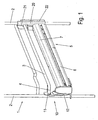
- a connecting device is used to fix a pullout guide 5 on a side rail 1, wherein the side rail 1 comprises two spaced vertical posts 2, where a plurality of horizontal struts 3 are fixed.
- Each horizontal strut 3 comprises on one side an angled end portion 4 which is fixed to the vertical post 2.
- On the opposite side of each horizontal strut 3 is fixed with a linear portion end to a vertical post 2.
- the side rail 1 is fixed, for example, on a side wall of a baking oven and serves to guide Gargutlinin, wherein at least a part of the horizontal struts 3 a pullout guide 5 is fixed to a stationary guide rail 6 and a movable running rail 7. Between the guide rail 6 and the running rail 7 can be arranged at least one Statisticssverinrnde middle rail.
- a first holder 10 is fixed, which has a hook 11 which is hooked to the angled end portion 4 of a horizontal strut 3.
- a spring element 12 is provided.
- the connecting device comprises a second holder 20, which is fixed to the rear post 2 of the side rail 1.
- the second holder 20 includes a hook 21 which is hooked to a horizontal strut 3.
- the second holder 20 comprises a strip-shaped portion 22 which surrounds the vertical post 2 in a U-shape.
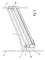
- FIG. 2 the connecting device is shown during assembly, wherein the second holder 20 is already fixed to the vertical post 2 and the horizontal strut 3 and the first holder 10 is not yet fixed to the angled end portion 4.
- the spring element 12 is bent away from the hook 11 so that the angled end portion 4 can be inserted into the hook 11. Subsequently, the spring element 12 bends back and secures the first holder.
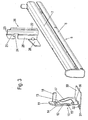
- the first holder 10 and the second holder 20 is shown with not yet arranged pullout guide 5.
- the first holder 10 is substantially angularly configured, wherein on one side of the hook 11 and on the other side an angled portion 30 is formed, on which the pullout guide is supported.
- the pullout guide 5 can with a rail be fixed to the angled portion 30, for example by welding.
- Adjacent to the hook 11, an angled stop 18 is formed, which is aligned parallel to the angled end portion 4 and rests against the horizontal strut 3
- the holder 10 can be secured against pulling transversely to the extension direction.
- a horizontally aligned tab 31 is formed on the back, on which a recess 32 is provided for inserting the post 2.
- the spring element 12 comprises a bendable spring leg 15, on which a lateral projection 13 is formed in order to close an opening 19 on the hook 11. Further, an angled stop 14 is formed on the spring leg 15 in order to limit the movement of the spring leg 15. Further, the stopper 14 serves as a handle in disassembling the pullout guide 5.
- the spring member 12 further includes a bottom portion 16 which is disposed adjacent to the angled portion 30 on the holder 10 so as to prevent the spring member 12 from being moved downward can. Further, a boom 17 is integrally formed on the bottom portion 16.
- the second holder 20 comprises a strip-shaped portion 22 on which a U-shaped groove 23 is formed for receiving the vertical post 2.
- a laterally projecting hook 21 is formed, which has an opening 24 for insertion of the horizontal strut 3.
- a laterally projecting bar 25 is formed, on which an angle projecting arm 26 is arranged.
- the boom 26 extends parallel to the longitudinal direction of the pullout guide 5 and can be inserted into a receptacle on a guide rail 6.
- the guide rail 6 may be fixed by suitable fastening means.
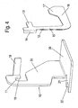
- the holder 10 is formed as an angle and comprises a horizontal angled portion 30 and a vertical angle portion 33. At the vertical angle portion 33 of the hook 11 is formed with an opening 19 for insertion of the angled end portion 4.
- the holder 10 is made of a bent and stamped sheet metal.
- the spring element 12 is made substantially plate-shaped from a metal sheet and has a substantially L-shaped contour.
- the spring leg 12 in this case includes the angled stop 14 and the projection 13 on the side facing the bending axis of the bottom portion 16 is arranged with the modified here boom 17 ', which may be glued or welded to the vertical portion 33.
- the spring element 12 is designed as a leaf spring, wherein instead of the flat plate-like structure and a spring element 12 can be used from a round wire or other geometry.
- a spring element 12 " is provided, which has a projection 13 adjacent to a stop 14 for closing the opening 19.
- the spring element 12" is substantially strip-shaped and flat and comprises a bottom section 16 which is adjacent to the angled section 30 of the holder 10 is arranged.
- a spring limb 17 " Extending in an arcuately recessed transition region, a spring limb 17 ", which has an end 37 in an arcuately recessed transition region, has an end 37 in an arcuately recessed transition region the spring element 12 "is comparatively long due to the wound section 37, so that a spring force can be provided in a particularly compact design
- the large resilient length achieved by the transition regions permits the use of cost-effective materials with a smaller elastic range.
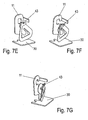
- a spring element 12 "' is provided which, in the region of the hook 11, has a stop 14 and a projection 13, as in the preceding embodiments.
- the spring element 12"' comprises a spring leg 17 "'extending from the angled section 30 of the holder 10 comprises an outer spiral winding 40 and an inner spiral winding 41.
- the helical windings 40 and 41 provide a particularly long spring leg 15 in a compact design, which can also serve as a lateral support surface while being welded or glued to the vertical portion 33 of the holder 10.
- a spring element 12 "" in the form of a flat-form spring is provided, which is a modification to that in FIG FIG. 5 illustrated embodiment represents.
- the spring element 12 "" comprises a section 42 for securing the flat shape spring against unintentional release.
- the section 42 has for this purpose a U-shaped cross section and engages around an edge on the hook 11.
- To release the spring element 12 "” has a handle 43 in the form of a projection. To release, the user must deflect the spring member 12 "” in the direction away from the hook 11 so that the portion 42 disengages from the hook 11 before it can deflect the spring member 12 "" across its main plane to the connection to solve.
- FIG. 8 schematically shows the characteristic of a flat shape spring 44 according to the Figures 5 and 7 ,
- the flat shape spring 44 is welded to a fixing 49 on the vertical angle section 33 of the holder 10. In this area, no deformation in the form of bending occurs.
- a force attack 45 At the vertical spring portion creates a strong bend 48 in the direction of the negative z-axis.
- a force attack 45 also turns a strong bend 46 in the form of a deflection.
- the force acts in the z direction on the spring and causes equiaxed deformation.
- the horizontal leg of the flat-form spring exhibits only a slight bend 47 over its entire length. The direction of the deflection is determined by the vertical and diagonal spring sections and thus moves from the positive z-axis into the negative.
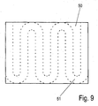
- FIG. 9 shows an example of a modified Flachformfederzurough 51. From a plate-shaped rectangular base surface 50 of the sheet, a meander-shaped Flachformfederzuites 51 is obtained. Thus, a flat form spring is produced with a large deflection across the material thickness with low material usage. Incidentally, the flat-form spring may be formed like the preceding embodiments.
Description
Die vorliegende Erfindung betrifft eine Verbindungseinrichtung und ein Seitengitter zur Fixierung einer Auszugsführung an dem Seitengitter, insbesondere für Backöfen, mit einem Halter, der mindestens einen Haken zum Einhängen an einer horizontalen Strebe des Seitengitters aufweist, und ein Federelement, mittels dem der Halter an dem Seitengitter verrastbar ist.The present invention relates to a connecting device and a side rail for fixing a pull-out guide on the side rails, in particular for ovens, with a holder having at least one hook for hanging on a horizontal strut of the side rail, and a spring element, by means of which the holder on the side rail is latched.
Die
Die
Es ist daher Aufgabe der vorliegenden Erfindung, eine Verbindungseinrichtung und ein Seitengitter zur Fixierung einer Auszugsführung an dem Seitengitter zu schaffen, die leicht zu montieren ist und bei der eine hohe Materialbelastung des Federelementes vermieden werden kann.It is therefore an object of the present invention to provide a connecting device and a side rail for fixing a pullout guide on the side rails, which is easy to install and in which a high material loading of the spring element can be avoided.
Diese Aufgabe wird mit einer Verbindungseinrichtung und einem Seitengitter mit den Merkmalen des Anspruches 1 gelöst.This object is achieved with a connecting device and a side rail with the features of
Erfindungsgemäß ist das Federelement der Verbindungseinrichtung als separates Bauteil ausgebildet, also getrennt von dem Halter, und umfasst einen biegbaren Federschenkel zum Verrasten des Halters. Der biegbare Federschenkel kann einen größeren Federweg aufweisen, so dass geringere Kräfte beim Verrasten des Halters an der Strebe notwendig sind. Zudem kann das Federelement in eine Richtung biegbar ausgebildet sein, in der der Halter eine hohe Steifigkeit besitzt, so dass eine optimierte Gestaltung zur sicheren Fixierung an der Strebe möglich ist.According to the invention, the spring element of the connecting device is designed as a separate component, that is to say separate from the holder, and comprises a bendable spring leg for latching the holder. The bendable spring leg may have a greater spring travel, so that lower forces are necessary when locking the holder on the strut. In addition, the spring element can be made bendable in one direction, in which the holder has a high rigidity, so that an optimized design for secure fixation on the strut is possible.
Vorzugsweise ist das Federelement an dem Halter in der verrasteten Position fixiert. Das Federelement kann dabei klemmend an dem Halter festgelegt sein, aber auch eine Festlegung über Befestigungsmittel ist möglich.Preferably, the spring element is fixed to the holder in the latched position. The spring element can be clamped fixed to the holder, but also a determination of attachment means is possible.
Gemäß einer Ausgestaltung der Erfindung ist der Halter als Winkel ausgebildet, der an einer Seite den Haken und an einem abgewinkelten Abschnitt eine Auflage für die Auszugsführung ausbildet. Dadurch kann an dem abgewinkelten Abschnitt auf einfache Weise die Auszugsführung festgelegt werden. Für eine stabile Befestigung in horizontaler Richtung kann an dem abgewinkelten Abschnitt eine Aussparung ausgebildet sein, in die ein vertikaler Pfosten des Seitengitters einfügbar ist. Dadurch werden die beim Verfahren der Auszugsführung auftretenden horizontalen Kräfte direkt auf das Seitengitter übertragen.According to one embodiment of the invention, the holder is formed as an angle, which forms on one side of the hook and an angled portion a support for the pullout guide. As a result, the pull-out guide can be fixed to the angled section in a simple manner. For a stable attachment in the horizontal direction may be formed on the angled portion a recess into which a vertical post of the side rail can be inserted. As a result, the horizontal forces occurring during the movement of the drawer guide are transmitted directly to the side rail.
Für einen kompakten Aufbau kann das Federelement als Blattfeder ausgebildet sein. Der biegbare Federschenkel kann für geringe Federkräfte eine Länge von mindestens 2 cm aufweisen.For a compact design, the spring element may be formed as a leaf spring. The bendable spring leg may have a length of at least 2 cm for low spring forces.
Das Federelement ist erfindungsgemäß entweder im Wesentlichen L-förmig ausgebildet, wobei ein Schenkel den Federschenkel bildet und der andere Schenkel an dem abgewinkelten Abschnitt des Halters abgestützt ist oder es weist einen aus dem Blech bogenförmig, insbesondere spiralförmig gestalteten Federschenkel auf. Dadurch ist ein besonders flacher Aufbau des Federelementes möglich, das im Wesentlichen aus einem gebogenen Metallblech hergestellt sein kann, wobei an dem Federschenkel zusätzlich ein gebogener Anschlag zur Begrenzung des Federweges des Federschenkels vorgesehen sein kann beziehungsweise es kann bei sehr kompakter Bauweise eine leichte Auslenkung quer zur Blechebene des Federschenkels über einen großen Federweg erreicht werden.The spring element according to the invention is either substantially L-shaped, with one leg forming the spring leg and the other leg is supported on the angled portion of the holder or it has an arcuate from the sheet, in particular spirally shaped spring legs. As a result, a particularly flat structure of the spring element is possible, which may be made essentially of a bent metal sheet, wherein on the spring leg additionally a curved stop for limiting the spring travel of the spring leg can be provided or it can be a very small design transverse deflection to the Sheet plane of the spring leg over a large travel can be achieved.
Ziel dieser Federanordnung ist es, bezogen auf die Grundfläche der Flachformfeder die maximale, gestreckte Länge bezogen auf den Zuschnitt zu erhalten.The aim of this spring arrangement is based on the base of the flat form spring to obtain the maximum, extended length based on the blank.
Die Verbindungseinrichtung umfasst vorzugsweise einen zweiten Halter, der beispielsweise am gegenüberliegenden Ende der Auszugsführung montiert sein kann und einen Haken zum Einhängen an einer horizontalen Strebe des Seitengitters aufweist. Der zweite Halter umfasst für eine sichere Fixierung an dem Seitengitter einen leistenförmigen Abschnitt, an dem eine Nut zum Einfügen eines vertikalen Pfostens des Seitengitters ausgebildet ist, so dass horizontale Kräfte auf das Seitengitter übertragen werden können. Für eine stabile Befestigung der Auszugsführung kann an dem zweiten Halter ein horizontaler Ausleger vorgesehen sein, an dem eine Schiene der Auszugsführung festgelegt ist, beispielsweise durch Einstecken des Auslegers in die Schiene.The connecting device preferably comprises a second holder, which may for example be mounted at the opposite end of the drawer guide and has a hook for hanging on a horizontal strut of the side rail. The second holder includes for secure fixation on the side rail a strip-shaped portion on which a groove for inserting a vertical post of the side rail is formed so that horizontal forces can be transmitted to the side rails. For a stable attachment of the drawer guide may be provided on the second holder, a horizontal arm on which a rail of the drawer guide is set, for example by inserting the boom in the rail.
Die Erfindung wird nachfolgend anhand eines Ausführungsbeispiels mit Bezug auf die beigefügten Zeichnungen näher erläutert. Es zeigen:
Figur 1- eine perspektivische Ansicht der Verbindungseinrichtung im montierten Zustand;
Figur 2- eine perspektivische Ansicht der Verbindungseinrichtung der
Figur 1 Figur 3- eine perspektivische Explosionsdarstellung der Verbindungseinrichtung ohne Seitengitter,
Figur 4- eine perspektivische Ansicht des ersten Halters und des Federelementes,
- Figur 5A bis 5C
- mehrere Ansichten eines weiteren Ausführungsbeispieles eines ersten Halters mit einem modifizierten Federelement,
- Figuren 6A bis 6C
- mehrere Ansichten eines weiteren Ausführungsbeispieles eines ersten Halters mit einem modifizierten Federelement,
- Figuren 7A bis 7G
- mehrere Ansichten eines weiteren Ausführungsbeispieles eines ersten Halters mit einem modifizierten Federelement,
- Figur 8
- eine schematische Darstellung der Verformung der Flachformfeder der
Fig. 7 bei Krafteinwirkung, und - Figur 9
- ein Beispiel für einen modifizierten Flachformfederzuschnitt.
- FIG. 1
- a perspective view of the connecting device in the assembled state;
- FIG. 2
- a perspective view of the connecting device of
FIG. 1 during installation; - FIG. 3
- an exploded perspective view of the connecting device without side rails,
- FIG. 4
- a perspective view of the first holder and the spring element,
- FIGS. 5A to 5C
- several views of a further embodiment of a first holder with a modified spring element,
- FIGS. 6A to 6C
- several views of a further embodiment of a first holder with a modified spring element,
- FIGS. 7A to 7G
- several views of a further embodiment of a first holder with a modified spring element,
- FIG. 8
- a schematic representation of the deformation of the flat spring of
Fig. 7 when force, and - FIG. 9
- an example of a modified Flachformfederzuschnitt.
Eine Verbindungseinrichtung dient zur Fixierung einer Auszugsführung 5 an einem Seitengitter 1, wobei das Seitengitter 1 zwei voneinander beabstandete vertikale Pfosten 2 umfasst, an denen eine Vielzahl horizontaler Streben 3 festgelegt sind. Jede horizontale Strebe 3 umfasst an einer Seite einen abgewinkelten Endabschnitt 4, der an dem vertikalen Pfosten 2 festgelegt ist. Auf der gegenüberliegenden Seite ist jede horizontale Strebe 3 mit einem linearen Abschnitt endseitig an einem vertikalen Pfosten 2 festgelegt.A connecting device is used to fix a
Das Seitengitter 1 wird beispielsweise an einer Seitenwand eines Backofens fixiert und dient zur Führung von Gargutträgern, wobei zumindest an einem Teil der horizontalen Streben 3 eine Auszugsführung 5 mit einer stationären Führungsschiene 6 und einer verfahrbaren Laufschiene 7 festgelegt ist. Zwischen der Führungsschiene 6 und der Laufschiene 7 kann mindestens eine auszugsverlängernde Mittelschiene angeordnet sein.The
An dem vorderen Pfosten 2 ist ein erster Halter 10 festgelegt, der einen Haken 11 aufweist, der an dem abgewinkelten Endabschnitt 4 einer horizontalen Strebe 3 eingehängt ist. Um den Haken 11 in der eingehängten Position zu sichern, ist ein Federelement 12 vorgesehen.At the
Ferner umfasst die Verbindungseinrichtung einen zweiten Halter 20, der an dem hinteren Pfosten 2 des Seitengitters 1 festgelegt ist. Der zweite Halter 20 umfasst einen Haken 21, der an einer horizontalen Strebe 3 eingehängt ist. Ferner umfasst der zweite Halter 20 einen leistenförmigen Abschnitt 22, der den vertikalen Pfosten 2 U-förmig einfasst.Furthermore, the connecting device comprises a
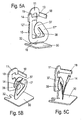
In
In
An dem abgewinkelten Abschnitt 30 ist rückseitig eine horizontal ausgerichtete Lasche 31 ausgebildet, an der eine Aussparung 32 zum Einfügen des Pfostens 2 vorgesehen ist. Dadurch kann der Halter 12 gegen ein Verschieben in Auszugsrichtung gesichert werden.At the
Das Federelement 12 umfasst einen biegbaren Federschenkel 15, an dem ein seitlicher Vorsprung 13 ausgebildet ist, um eine Öffnung 19 an dem Hakten 11 zu verschließen. Ferner ist an dem Federschenkel 15 ein abgewinkelter Anschlag 14 ausgebildet, um die Bewegung des Federschenkels 15 zu begrenzen. Weiterhin dient der Anschlag 14 als Handhabe bei der Demontage der Auszugsführung 5. Das Federelement 12 umfasst ferner einen Bodenabschnitt 16, der benachbart zu dem abgewinkelten Abschnitt 30 an dem Halter 10 angeordnet ist, so dass verhindert wird, dass das Federelement 12 nach unten bewegt werden kann. Ferner ist an dem Bodenabschnitt 16 ein Ausleger 17 angeformt.The
Der zweite Halter 20 umfasst einen leistenförmigen Abschnitt 22, an dem eine U-förmige Nut 23 zur Aufnahme des vertikalen Pfostens 2 ausgebildet ist. An einem seitlichen Schenkel des leistenförmigen Abschnittes 22 ist ein seitlich hervorstehender Haken 21 ausgebildet, der eine Öffnung 24 zum Einfügen der horizontalen Strebe 3 aufweist. Ferner ist an einem Schenkel des leistenförmigen Abschnittes 22 eine seitlich hervorstehende Leiste 25 ausgebildet, an der ein winklig hervorstehender Ausleger 26 angeordnet ist. Der Ausleger 26 erstreckt sich parallel zur Längsrichtung der Auszugsführung 5 und kann in eine Aufnahme an einer Führungsschiene 6 eingefügt werden. An dem Ausleger 26 kann die Führungsschiene 6 durch geeignete Befestigungsmittel fixiert sein.The
In
Auch das Federelement 12 ist im Wesentlichen plattenförmig aus einem Metallblech hergestellt und besitzt eine im Wesentlichen L-förmige Kontur. Der Federschenkel 12 umfasst dabei endseitig den abgewinkelten Anschlag 14 und den Vorsprung 13. Auf der zur Biegeachse gewandten Seite ist der Bodenabschnitt 16 mit dem hier modifiziert ausgebildeten Ausleger 17' angeordnet, der an dem vertikalen Abschnitt 33 verklebt oder verschweißt sein kann. Das Federelement 12 ist als Blattfeder ausgebildet, wobei statt des flachen plattenförmigen Aufbaus auch ein Federelement 12 aus einem Runddraht oder einer anderen Geometrie eingesetzt werden kann.Also, the
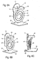
In den
Bei den in
Bei den in
Die
Die
- 11
- Seitengitterside rails
- 22
- Pfostenpost
- 33
- Strebestrut
- 44
- Endabschnittend
- 55
- Auszugsführungpull-out guide
- 66
- Führungsschieneguide rail
- 77
- Laufschienerunner
- 1010
- Halterholder
- 1111
- Hakenhook
- 1212
- Federelementspring element
- 12"12 "
- Federelementspring element
- 12"'12 " '
- Federelementspring element
- 12""12 ""
- Federelementspring element
- 1313
- Vorsprunghead Start
- 1414
- Anschlagattack
- 1515
- Federschenkelspring leg
- 1616
- Bodenabschnittbottom section
- 1717
- Auslegerboom
- 17'17 '
- Auslegerboom
- 17"17 "
- Federschenkelspring leg
- 17"'17 " '
- Federschenkelspring leg
- 1818
- Anschlagattack
- 1919
- Öffnungopening
- 2020
- Halterholder
- 2121
- Hakenhook
- 2222
- Abschnittsection
- 2323
- Nutgroove
- 2424
- Öffnungopening
- 2525
- Leistestrip
- 2626
- Auslegerboom
- 3030
- Abschnittsection
- 3131
- Lascheflap
- 3232
- Aussparungrecess
- 3333
- Winkelabschnittangle section
- 3737
- Abschnittsection
- 3838
- EndeThe End
- 4040
- Wicklungwinding
- 4141
- Wicklungwinding
- 4242
- Abschnittsection
- 4343
- Handhabehandle
- 4444
- FlachformfederFlat form spring
- 4545
- Kraftangriffof force
- 4646
- starke Biegungstrong bend
- 4747
- leichte Biegungslight bend
- 4848
- starke Biegungstrong bend
- 4949
- Fixierungfixation
- 5050
- GrundflächeFloor space
- 5151
- FlachformfederzuschnittFlatform spring cut
Claims (13)
- Connecting device and side grate (1) for fixing a pull-out guide (5) to the side grate (1), in particular for baking ovens, with a holder (10) which has at least one hook (11) for hooking onto a horizontal strut (3) of the side grate (1), and with a spring element (12, 12", 12"', 12"") by means of which the holder (10) can be latched to the side grate (1), wherein the spring element (12, 12", 12"', 12"") is designed as a separate component and has a bendable spring leg (15) for latching the holder (10), characterized in that the spring element 12, 12", 12"') is substantially L-shaped, wherein one leg forms the spring leg (15), which bears against an angular portion (33) of the holder (10), and the other leg (16) is supported on a portion (30) of the holder (10) that is angled off with respect to the angular portion (33), or the spring element (12", 12"', 12"") comprises a spiral blank composed of a flat spring.
- Connecting device and side grate according to Claim 1, characterized in that the spring element (12, 12", 12"', 12"") is fixed to the holder (10) in the latched position.
- Connecting device and side grate according to Claim 1 or 2, characterized in that the holder (10) takes the form of an angle bracket which forms the hook (11) on one side and forms a support for the pull-out guide (5) on an angled-off portion (30).
- Connecting device and side grate according to Claim 1, characterized in that a cutout (32) into which a vertical post (2) of the side grate (1) can be inserted is formed in the angled-off portion (30).
- Connecting device and side grate according to one of the preceding claims, characterized in that the spring element (12, 12", 12"') takes the form of a leaf spring.
- Connecting device and side grate according to one of the preceding claims, characterized in that the bendable spring leg (15) has a length of at least 2 cm.
- Connecting device and side grate according to one of the preceding claims, characterized in that a second holder (20) is provided which has a hook (21) for hooking onto a horizontal strut (3) of the side grate (1).
- Connecting device and side grate according to Claim 7, characterized in that the second holder (20) has a strip-like portion in which a groove (23) for inserting a vertical post (2) of the side grate (1) is formed.
- Connecting device and side grate according to Claim 7 or 8, characterized in that a horizontal extension arm (26) on which a rail (6) of the pull-out guide (5) is secured is provided on the second holder (20).
- Connecting device and side grate according to Claim 9, characterized in that the extension arm (26) can be inserted into the rail (6).
- Connecting device and side grate according to one of the preceding claims, characterized in that the spring element (12", 12"') has a spring leg (17", 17"') which is wound in on itself and is in particular wound in a spiral shape.
- Connecting device and side grate according to one of the preceding claims, characterized in that the first holder (10), the second holder (20) and/or the spring element (12, 12", 12"', 12"") are produced from a metal sheet.
- Pull-out guide with a connecting device with side grate according to at least one of Claims 1 to 12.
Applications Claiming Priority (3)
| Application Number | Priority Date | Filing Date | Title |
|---|---|---|---|
| DE102010036422 | 2010-07-15 | ||
| DE102011002257A DE102011002257A1 (en) | 2010-07-15 | 2011-04-26 | Connecting device for fixing a pullout guide on a side rail |
| PCT/EP2011/061595 WO2012007372A1 (en) | 2010-07-15 | 2011-07-08 | Connecting device for fixing a pull-out guide to a side grate |
Publications (2)
| Publication Number | Publication Date |
|---|---|
| EP2592968A1 EP2592968A1 (en) | 2013-05-22 |
| EP2592968B1 true EP2592968B1 (en) | 2015-10-28 |
Family
ID=45403071
Family Applications (1)
| Application Number | Title | Priority Date | Filing Date |
|---|---|---|---|
| EP11730313.1A Active EP2592968B1 (en) | 2010-07-15 | 2011-07-08 | Connecting device and side grate for fixing a pull-out guide to said side grate |
Country Status (6)
| Country | Link |
|---|---|
| US (1) | US20130156353A1 (en) |
| EP (1) | EP2592968B1 (en) |
| KR (1) | KR20130131298A (en) |
| CN (1) | CN103002772B (en) |
| DE (1) | DE102011002257A1 (en) |
| WO (1) | WO2012007372A1 (en) |
Families Citing this family (7)
| Publication number | Priority date | Publication date | Assignee | Title |
|---|---|---|---|---|
| DE102012215140A1 (en) * | 2012-08-27 | 2014-02-27 | BSH Bosch und Siemens Hausgeräte GmbH | Retention device of receiving apparatus for food carrier used in cooking apparatus e.g. oven, has receiving elements that are formed as eyelet on support rods for coupling the receiving apparatus |
| JP5820829B2 (en) * | 2013-01-24 | 2015-11-24 | 京セラドキュメントソリューションズ株式会社 | Slide rail and image forming apparatus having the same |
| DE102013013034A1 (en) * | 2013-08-05 | 2015-02-05 | Laag S.R.L. | Suspension grille for a device, in particular an oven |
| DE202014104795U1 (en) * | 2014-10-07 | 2016-01-11 | Grass Gmbh | Device for guiding the movement of a pushing element, pushing element and furniture |
| CN109463407B (en) * | 2018-09-03 | 2024-02-06 | 江苏玖星精密科技集团有限公司 | Oven slide rail loading and unloading mechanism with locking function |
| US20230037625A1 (en) * | 2021-08-09 | 2023-02-09 | Segos Co., Ltd. | Fixing Means |
| US20230189992A1 (en) * | 2021-12-22 | 2023-06-22 | Grass America, Inc. | Guide rail, guide system and furniture item |
Family Cites Families (18)
| Publication number | Priority date | Publication date | Assignee | Title |
|---|---|---|---|---|
| US5165640A (en) * | 1991-10-04 | 1992-11-24 | Williams 3Rd James W | Spring clip for perforated board tool holders |
| FR2746840B1 (en) * | 1996-03-26 | 1998-05-29 | Ymos France | MOTOR VEHICLE DOOR LOCK |
| US5831829A (en) * | 1996-07-18 | 1998-11-03 | Lin; Mike | Heat dissipating device for central processing units |
| GB2337295B (en) * | 1998-05-12 | 2000-08-02 | Mitsui Mining & Smelting Co | Anti-panic vehicle door latch device |
| FR2789716B1 (en) * | 1999-02-16 | 2001-06-29 | Valeo Securite Habitacle | LOCK FOR AN OPENING ELEMENT OF A MOTOR VEHICLE, WITH LOCKING STORAGE |
| US6327758B1 (en) * | 1999-11-01 | 2001-12-11 | Juno Manufacturing, Inc. | Resilient unitary lighting clip |
| PT1158185E (en) * | 2000-05-26 | 2005-11-30 | Hettich Paul Gmbh & Co | FAST FIXING ELEMENT |
| US6422399B1 (en) * | 2000-11-21 | 2002-07-23 | Dell Products L.P. | Rack system and method having tool-less releasable arm assembly |
| KR100445177B1 (en) * | 2002-04-19 | 2004-08-21 | 현대자동차주식회사 | Cup holder of an automobile |
| US6773080B2 (en) * | 2002-12-06 | 2004-08-10 | King Slide Works, Co., Ltd. | Bracket device for a track assembly |
| US20040263032A1 (en) * | 2003-06-28 | 2004-12-30 | Cho Han Ki | Stand for home appliance |
| US6904650B2 (en) * | 2003-09-03 | 2005-06-14 | Inventec Corporation | Unlocking mechanism |
| DE202005020458U1 (en) | 2005-12-29 | 2007-05-16 | Paul Hettich Gmbh & Co. Kg | Quick fastener |
| DE202006002251U1 (en) * | 2006-02-10 | 2007-06-21 | Paul Hettich Gmbh & Co. Kg | Guide rail with a quick-fastening device |
| TW200944157A (en) * | 2008-04-18 | 2009-11-01 | King Slide Works Co Ltd | Positioning device for a drawer with a drawer slide |
| DE202009003047U1 (en) * | 2009-03-06 | 2010-07-22 | Paul Hettich Gmbh & Co. Kg | mounting assembly |
| SE534688C2 (en) * | 2009-03-20 | 2011-11-15 | Pricer Ab | Electronic shelf label and holder including locking mechanism, and locking mechanism |
| US9103078B2 (en) * | 2009-11-24 | 2015-08-11 | Kenco Engineering, Inc. | Screed plate |
-
2011
- 2011-04-26 DE DE102011002257A patent/DE102011002257A1/en not_active Withdrawn
- 2011-07-08 US US13/809,978 patent/US20130156353A1/en not_active Abandoned
- 2011-07-08 CN CN201180034753.9A patent/CN103002772B/en not_active Expired - Fee Related
- 2011-07-08 KR KR1020137003753A patent/KR20130131298A/en not_active Application Discontinuation
- 2011-07-08 EP EP11730313.1A patent/EP2592968B1/en active Active
- 2011-07-08 WO PCT/EP2011/061595 patent/WO2012007372A1/en active Application Filing
Also Published As
| Publication number | Publication date |
|---|---|
| KR20130131298A (en) | 2013-12-03 |
| DE102011002257A1 (en) | 2012-01-19 |
| CN103002772B (en) | 2015-03-11 |
| CN103002772A (en) | 2013-03-27 |
| US20130156353A1 (en) | 2013-06-20 |
| EP2592968A1 (en) | 2013-05-22 |
| WO2012007372A1 (en) | 2012-01-19 |
Similar Documents
| Publication | Publication Date | Title |
|---|---|---|
| EP2592968B1 (en) | Connecting device and side grate for fixing a pull-out guide to said side grate | |
| EP2310693B1 (en) | Quick-action fastening element | |
| EP3198201B1 (en) | Method for fastening a pull-out guide to a side grate | |
| EP2406548B1 (en) | Pull-out device | |
| EP2517531B1 (en) | Holding device for a support of a heating body of a hob and hob, in particular, induction hob | |
| DE202009003045U1 (en) | Quick fastening device | |
| EP2403379B1 (en) | Fastening arrangement | |
| DE3524651A1 (en) | FASTENING CLIP | |
| EP2703237A1 (en) | Assembly group with a rain sensor and a holding clip for the rain sensor | |
| DE102012101220A1 (en) | drawer | |
| EP2317891A1 (en) | Pull-out guide for drawers, comprising a catch hook | |
| DE102010053409A1 (en) | U-shaped profile for clamped support of sheet of glass sheet railing, is clamped between two legs of foot area of sheet, particularly glass sheet of railing, which is stably fixed on structure | |
| EP3082508A1 (en) | Drawer wall element | |
| EP2790549B1 (en) | Side-rail arrangement | |
| WO2013087375A1 (en) | Fastening element and side-rail arrangement | |
| DE202010016185U1 (en) | U-profile for the clamped mounting of a handrail | |
| EP3852579B1 (en) | Drawer and unit made up of a pull-out guide and a drawer | |
| DE102010029768A1 (en) | Telescopic sliding-out device for household appliance i.e. cooking device, has movable rail provided with support surface on which load carrier is provided, where lowering unit is arranged between front and end sections of support surface | |
| DE102006041803B4 (en) | Device for attaching a device to a mounting rail | |
| DE102008041092A1 (en) | Circuit board with forming tube for guiding and supporting a drive shaft | |
| DE202007008150U1 (en) | Fixing device for solar modules | |
| DE102010039454A1 (en) | Closure for fastening device of surface element of fume extraction hood, has base with inlet opening for snap-in element and closure portion above base, where closure portion consists of two shanks connected with base and connecting bar | |
| DE4318828C2 (en) | Built-in device, especially built-in sink | |
| EP3968815B1 (en) | Side panel for a drawer | |
| DE202009012416U1 (en) | Fastening device for arranging a door frame on a wall |
Legal Events
| Date | Code | Title | Description |
|---|---|---|---|
| PUAI | Public reference made under article 153(3) epc to a published international application that has entered the european phase |
Free format text: ORIGINAL CODE: 0009012 |
|
| 17P | Request for examination filed |
Effective date: 20130111 |
|
| AK | Designated contracting states |
Kind code of ref document: A1 Designated state(s): AL AT BE BG CH CY CZ DE DK EE ES FI FR GB GR HR HU IE IS IT LI LT LU LV MC MK MT NL NO PL PT RO RS SE SI SK SM TR |
|
| DAX | Request for extension of the european patent (deleted) | ||
| GRAP | Despatch of communication of intention to grant a patent |
Free format text: ORIGINAL CODE: EPIDOSNIGR1 |
|
| INTG | Intention to grant announced |
Effective date: 20150515 |
|
| GRAS | Grant fee paid |
Free format text: ORIGINAL CODE: EPIDOSNIGR3 |
|
| GRAA | (expected) grant |
Free format text: ORIGINAL CODE: 0009210 |
|
| AK | Designated contracting states |
Kind code of ref document: B1 Designated state(s): AL AT BE BG CH CY CZ DE DK EE ES FI FR GB GR HR HU IE IS IT LI LT LU LV MC MK MT NL NO PL PT RO RS SE SI SK SM TR |
|
| REG | Reference to a national code |
Ref country code: GB Ref legal event code: FG4D Free format text: NOT ENGLISH |
|
| REG | Reference to a national code |
Ref country code: CH Ref legal event code: EP |
|
| REG | Reference to a national code |
Ref country code: AT Ref legal event code: REF Ref document number: 757447 Country of ref document: AT Kind code of ref document: T Effective date: 20151115 |
|
| REG | Reference to a national code |
Ref country code: IE Ref legal event code: FG4D Free format text: LANGUAGE OF EP DOCUMENT: GERMAN |
|
| REG | Reference to a national code |
Ref country code: DE Ref legal event code: R096 Ref document number: 502011008229 Country of ref document: DE |
|
| REG | Reference to a national code |
Ref country code: LT Ref legal event code: MG4D |
|
| REG | Reference to a national code |
Ref country code: NL Ref legal event code: MP Effective date: 20151028 |
|
| RIN2 | Information on inventor provided after grant (corrected) |
Inventor name: REHAGE, DANIEL |
|
| PG25 | Lapsed in a contracting state [announced via postgrant information from national office to epo] |
Ref country code: IT Free format text: LAPSE BECAUSE OF FAILURE TO SUBMIT A TRANSLATION OF THE DESCRIPTION OR TO PAY THE FEE WITHIN THE PRESCRIBED TIME-LIMIT Effective date: 20151028 Ref country code: IS Free format text: LAPSE BECAUSE OF FAILURE TO SUBMIT A TRANSLATION OF THE DESCRIPTION OR TO PAY THE FEE WITHIN THE PRESCRIBED TIME-LIMIT Effective date: 20160228 Ref country code: LT Free format text: LAPSE BECAUSE OF FAILURE TO SUBMIT A TRANSLATION OF THE DESCRIPTION OR TO PAY THE FEE WITHIN THE PRESCRIBED TIME-LIMIT Effective date: 20151028 Ref country code: ES Free format text: LAPSE BECAUSE OF FAILURE TO SUBMIT A TRANSLATION OF THE DESCRIPTION OR TO PAY THE FEE WITHIN THE PRESCRIBED TIME-LIMIT Effective date: 20151028 Ref country code: HR Free format text: LAPSE BECAUSE OF FAILURE TO SUBMIT A TRANSLATION OF THE DESCRIPTION OR TO PAY THE FEE WITHIN THE PRESCRIBED TIME-LIMIT Effective date: 20151028 Ref country code: NL Free format text: LAPSE BECAUSE OF FAILURE TO SUBMIT A TRANSLATION OF THE DESCRIPTION OR TO PAY THE FEE WITHIN THE PRESCRIBED TIME-LIMIT Effective date: 20151028 Ref country code: NO Free format text: LAPSE BECAUSE OF FAILURE TO SUBMIT A TRANSLATION OF THE DESCRIPTION OR TO PAY THE FEE WITHIN THE PRESCRIBED TIME-LIMIT Effective date: 20160128 |
|
| PG25 | Lapsed in a contracting state [announced via postgrant information from national office to epo] |
Ref country code: RS Free format text: LAPSE BECAUSE OF FAILURE TO SUBMIT A TRANSLATION OF THE DESCRIPTION OR TO PAY THE FEE WITHIN THE PRESCRIBED TIME-LIMIT Effective date: 20151028 Ref country code: GR Free format text: LAPSE BECAUSE OF FAILURE TO SUBMIT A TRANSLATION OF THE DESCRIPTION OR TO PAY THE FEE WITHIN THE PRESCRIBED TIME-LIMIT Effective date: 20160129 Ref country code: PL Free format text: LAPSE BECAUSE OF FAILURE TO SUBMIT A TRANSLATION OF THE DESCRIPTION OR TO PAY THE FEE WITHIN THE PRESCRIBED TIME-LIMIT Effective date: 20151028 Ref country code: LV Free format text: LAPSE BECAUSE OF FAILURE TO SUBMIT A TRANSLATION OF THE DESCRIPTION OR TO PAY THE FEE WITHIN THE PRESCRIBED TIME-LIMIT Effective date: 20151028 Ref country code: PT Free format text: LAPSE BECAUSE OF FAILURE TO SUBMIT A TRANSLATION OF THE DESCRIPTION OR TO PAY THE FEE WITHIN THE PRESCRIBED TIME-LIMIT Effective date: 20160229 Ref country code: FI Free format text: LAPSE BECAUSE OF FAILURE TO SUBMIT A TRANSLATION OF THE DESCRIPTION OR TO PAY THE FEE WITHIN THE PRESCRIBED TIME-LIMIT Effective date: 20151028 Ref country code: SE Free format text: LAPSE BECAUSE OF FAILURE TO SUBMIT A TRANSLATION OF THE DESCRIPTION OR TO PAY THE FEE WITHIN THE PRESCRIBED TIME-LIMIT Effective date: 20151028 |
|
| REG | Reference to a national code |
Ref country code: DE Ref legal event code: R083 Ref document number: 502011008229 Country of ref document: DE |
|
| PG25 | Lapsed in a contracting state [announced via postgrant information from national office to epo] |
Ref country code: CZ Free format text: LAPSE BECAUSE OF FAILURE TO SUBMIT A TRANSLATION OF THE DESCRIPTION OR TO PAY THE FEE WITHIN THE PRESCRIBED TIME-LIMIT Effective date: 20151028 |
|
| REG | Reference to a national code |
Ref country code: DE Ref legal event code: R097 Ref document number: 502011008229 Country of ref document: DE |
|
| PG25 | Lapsed in a contracting state [announced via postgrant information from national office to epo] |
Ref country code: RO Free format text: LAPSE BECAUSE OF FAILURE TO SUBMIT A TRANSLATION OF THE DESCRIPTION OR TO PAY THE FEE WITHIN THE PRESCRIBED TIME-LIMIT Effective date: 20151028 Ref country code: EE Free format text: LAPSE BECAUSE OF FAILURE TO SUBMIT A TRANSLATION OF THE DESCRIPTION OR TO PAY THE FEE WITHIN THE PRESCRIBED TIME-LIMIT Effective date: 20151028 Ref country code: SM Free format text: LAPSE BECAUSE OF FAILURE TO SUBMIT A TRANSLATION OF THE DESCRIPTION OR TO PAY THE FEE WITHIN THE PRESCRIBED TIME-LIMIT Effective date: 20151028 Ref country code: DK Free format text: LAPSE BECAUSE OF FAILURE TO SUBMIT A TRANSLATION OF THE DESCRIPTION OR TO PAY THE FEE WITHIN THE PRESCRIBED TIME-LIMIT Effective date: 20151028 Ref country code: SK Free format text: LAPSE BECAUSE OF FAILURE TO SUBMIT A TRANSLATION OF THE DESCRIPTION OR TO PAY THE FEE WITHIN THE PRESCRIBED TIME-LIMIT Effective date: 20151028 |
|
| PLBE | No opposition filed within time limit |
Free format text: ORIGINAL CODE: 0009261 |
|
| STAA | Information on the status of an ep patent application or granted ep patent |
Free format text: STATUS: NO OPPOSITION FILED WITHIN TIME LIMIT |
|
| 26N | No opposition filed |
Effective date: 20160729 |
|
| REG | Reference to a national code |
Ref country code: DE Ref legal event code: R079 Ref document number: 502011008229 Country of ref document: DE Free format text: PREVIOUS MAIN CLASS: A47B0088040000 Ipc: A47B0088400000 |
|
| PG25 | Lapsed in a contracting state [announced via postgrant information from national office to epo] |
Ref country code: SI Free format text: LAPSE BECAUSE OF FAILURE TO SUBMIT A TRANSLATION OF THE DESCRIPTION OR TO PAY THE FEE WITHIN THE PRESCRIBED TIME-LIMIT Effective date: 20151028 |
|
| PG25 | Lapsed in a contracting state [announced via postgrant information from national office to epo] |
Ref country code: BE Free format text: LAPSE BECAUSE OF NON-PAYMENT OF DUE FEES Effective date: 20160731 |
|
| REG | Reference to a national code |
Ref country code: CH Ref legal event code: PL |
|
| GBPC | Gb: european patent ceased through non-payment of renewal fee |
Effective date: 20160708 |
|
| PG25 | Lapsed in a contracting state [announced via postgrant information from national office to epo] |
Ref country code: MC Free format text: LAPSE BECAUSE OF FAILURE TO SUBMIT A TRANSLATION OF THE DESCRIPTION OR TO PAY THE FEE WITHIN THE PRESCRIBED TIME-LIMIT Effective date: 20151028 |
|
| PG25 | Lapsed in a contracting state [announced via postgrant information from national office to epo] |
Ref country code: LI Free format text: LAPSE BECAUSE OF NON-PAYMENT OF DUE FEES Effective date: 20160731 Ref country code: CH Free format text: LAPSE BECAUSE OF NON-PAYMENT OF DUE FEES Effective date: 20160731 Ref country code: FR Free format text: LAPSE BECAUSE OF NON-PAYMENT OF DUE FEES Effective date: 20160801 |
|
| REG | Reference to a national code |
Ref country code: FR Ref legal event code: ST Effective date: 20170331 |
|
| REG | Reference to a national code |
Ref country code: IE Ref legal event code: MM4A |
|
| PG25 | Lapsed in a contracting state [announced via postgrant information from national office to epo] |
Ref country code: GB Free format text: LAPSE BECAUSE OF NON-PAYMENT OF DUE FEES Effective date: 20160708 |
|
| PG25 | Lapsed in a contracting state [announced via postgrant information from national office to epo] |
Ref country code: IE Free format text: LAPSE BECAUSE OF NON-PAYMENT OF DUE FEES Effective date: 20160708 |
|
| PG25 | Lapsed in a contracting state [announced via postgrant information from national office to epo] |
Ref country code: LU Free format text: LAPSE BECAUSE OF NON-PAYMENT OF DUE FEES Effective date: 20160708 |
|
| REG | Reference to a national code |
Ref country code: AT Ref legal event code: MM01 Ref document number: 757447 Country of ref document: AT Kind code of ref document: T Effective date: 20160708 |
|
| PG25 | Lapsed in a contracting state [announced via postgrant information from national office to epo] |
Ref country code: AT Free format text: LAPSE BECAUSE OF NON-PAYMENT OF DUE FEES Effective date: 20160708 |
|
| REG | Reference to a national code |
Ref country code: DE Ref legal event code: R084 Ref document number: 502011008229 Country of ref document: DE |
|
| PG25 | Lapsed in a contracting state [announced via postgrant information from national office to epo] |
Ref country code: HU Free format text: LAPSE BECAUSE OF FAILURE TO SUBMIT A TRANSLATION OF THE DESCRIPTION OR TO PAY THE FEE WITHIN THE PRESCRIBED TIME-LIMIT; INVALID AB INITIO Effective date: 20110708 Ref country code: CY Free format text: LAPSE BECAUSE OF FAILURE TO SUBMIT A TRANSLATION OF THE DESCRIPTION OR TO PAY THE FEE WITHIN THE PRESCRIBED TIME-LIMIT Effective date: 20151028 |
|
| PG25 | Lapsed in a contracting state [announced via postgrant information from national office to epo] |
Ref country code: MT Free format text: LAPSE BECAUSE OF FAILURE TO SUBMIT A TRANSLATION OF THE DESCRIPTION OR TO PAY THE FEE WITHIN THE PRESCRIBED TIME-LIMIT Effective date: 20151028 Ref country code: MK Free format text: LAPSE BECAUSE OF FAILURE TO SUBMIT A TRANSLATION OF THE DESCRIPTION OR TO PAY THE FEE WITHIN THE PRESCRIBED TIME-LIMIT Effective date: 20151028 Ref country code: TR Free format text: LAPSE BECAUSE OF FAILURE TO SUBMIT A TRANSLATION OF THE DESCRIPTION OR TO PAY THE FEE WITHIN THE PRESCRIBED TIME-LIMIT Effective date: 20151028 |
|
| PG25 | Lapsed in a contracting state [announced via postgrant information from national office to epo] |
Ref country code: BG Free format text: LAPSE BECAUSE OF FAILURE TO SUBMIT A TRANSLATION OF THE DESCRIPTION OR TO PAY THE FEE WITHIN THE PRESCRIBED TIME-LIMIT Effective date: 20151028 |
|
| PG25 | Lapsed in a contracting state [announced via postgrant information from national office to epo] |
Ref country code: AL Free format text: LAPSE BECAUSE OF FAILURE TO SUBMIT A TRANSLATION OF THE DESCRIPTION OR TO PAY THE FEE WITHIN THE PRESCRIBED TIME-LIMIT Effective date: 20151028 |
|
| P01 | Opt-out of the competence of the unified patent court (upc) registered |
Effective date: 20230422 |
|
| PGFP | Annual fee paid to national office [announced via postgrant information from national office to epo] |
Ref country code: DE Payment date: 20230720 Year of fee payment: 13 |