EP2592846A1 - Method and apparatus for processing signals of a spherical microphone array on a rigid sphere used for generating an Ambisonics representation of the sound field - Google Patents
Method and apparatus for processing signals of a spherical microphone array on a rigid sphere used for generating an Ambisonics representation of the sound field Download PDFInfo
- Publication number
- EP2592846A1 EP2592846A1 EP11306472.9A EP11306472A EP2592846A1 EP 2592846 A1 EP2592846 A1 EP 2592846A1 EP 11306472 A EP11306472 A EP 11306472A EP 2592846 A1 EP2592846 A1 EP 2592846A1
- Authority
- EP
- European Patent Office
- Prior art keywords
- noise
- power
- transfer function
- array
- microphone
- Prior art date
- Legal status (The legal status is an assumption and is not a legal conclusion. Google has not performed a legal analysis and makes no representation as to the accuracy of the status listed.)
- Withdrawn
Links
Images


Classifications
-
- H—ELECTRICITY
- H04—ELECTRIC COMMUNICATION TECHNIQUE
- H04R—LOUDSPEAKERS, MICROPHONES, GRAMOPHONE PICK-UPS OR LIKE ACOUSTIC ELECTROMECHANICAL TRANSDUCERS; ELECTRIC HEARING AIDS; PUBLIC ADDRESS SYSTEMS
- H04R3/00—Circuits for transducers
- H04R3/005—Circuits for transducers for combining the signals of two or more microphones
-
- H—ELECTRICITY
- H04—ELECTRIC COMMUNICATION TECHNIQUE
- H04R—LOUDSPEAKERS, MICROPHONES, GRAMOPHONE PICK-UPS OR LIKE ACOUSTIC ELECTROMECHANICAL TRANSDUCERS; ELECTRIC HEARING AIDS; PUBLIC ADDRESS SYSTEMS
- H04R1/00—Details of transducers, loudspeakers or microphones
- H04R1/20—Arrangements for obtaining desired frequency or directional characteristics
- H04R1/32—Arrangements for obtaining desired frequency or directional characteristics for obtaining desired directional characteristic only
- H04R1/326—Arrangements for obtaining desired frequency or directional characteristics for obtaining desired directional characteristic only for microphones
-
- H—ELECTRICITY
- H04—ELECTRIC COMMUNICATION TECHNIQUE
- H04R—LOUDSPEAKERS, MICROPHONES, GRAMOPHONE PICK-UPS OR LIKE ACOUSTIC ELECTROMECHANICAL TRANSDUCERS; ELECTRIC HEARING AIDS; PUBLIC ADDRESS SYSTEMS
- H04R1/00—Details of transducers, loudspeakers or microphones
- H04R1/20—Arrangements for obtaining desired frequency or directional characteristics
- H04R1/32—Arrangements for obtaining desired frequency or directional characteristics for obtaining desired directional characteristic only
- H04R1/40—Arrangements for obtaining desired frequency or directional characteristics for obtaining desired directional characteristic only by combining a number of identical transducers
- H04R1/406—Arrangements for obtaining desired frequency or directional characteristics for obtaining desired directional characteristic only by combining a number of identical transducers microphones
-
- H—ELECTRICITY
- H04—ELECTRIC COMMUNICATION TECHNIQUE
- H04R—LOUDSPEAKERS, MICROPHONES, GRAMOPHONE PICK-UPS OR LIKE ACOUSTIC ELECTROMECHANICAL TRANSDUCERS; ELECTRIC HEARING AIDS; PUBLIC ADDRESS SYSTEMS
- H04R2201/00—Details of transducers, loudspeakers or microphones covered by H04R1/00 but not provided for in any of its subgroups
- H04R2201/40—Details of arrangements for obtaining desired directional characteristic by combining a number of identical transducers covered by H04R1/40 but not provided for in any of its subgroups
- H04R2201/401—2D or 3D arrays of transducers
-
- H—ELECTRICITY
- H04—ELECTRIC COMMUNICATION TECHNIQUE
- H04R—LOUDSPEAKERS, MICROPHONES, GRAMOPHONE PICK-UPS OR LIKE ACOUSTIC ELECTROMECHANICAL TRANSDUCERS; ELECTRIC HEARING AIDS; PUBLIC ADDRESS SYSTEMS
- H04R29/00—Monitoring arrangements; Testing arrangements
- H04R29/004—Monitoring arrangements; Testing arrangements for microphones
- H04R29/005—Microphone arrays
-
- H—ELECTRICITY
- H04—ELECTRIC COMMUNICATION TECHNIQUE
- H04R—LOUDSPEAKERS, MICROPHONES, GRAMOPHONE PICK-UPS OR LIKE ACOUSTIC ELECTROMECHANICAL TRANSDUCERS; ELECTRIC HEARING AIDS; PUBLIC ADDRESS SYSTEMS
- H04R5/00—Stereophonic arrangements
- H04R5/027—Spatial or constructional arrangements of microphones, e.g. in dummy heads
-
- H—ELECTRICITY
- H04—ELECTRIC COMMUNICATION TECHNIQUE
- H04S—STEREOPHONIC SYSTEMS
- H04S2400/00—Details of stereophonic systems covered by H04S but not provided for in its groups
- H04S2400/15—Aspects of sound capture and related signal processing for recording or reproduction
Definitions
- the invention relates to a method and to an apparatus for processing signals of a spherical microphone array on a rigid sphere used for generating an Ambisonics representation of the sound field, wherein an equalisation filter is applied to the inverse microphone array response.
- Spherical microphone arrays offer the ability to capture a three-dimensional sound field.
- One way to store and process the sound field is the Ambisonics representation.
- Ambisonics uses orthonormal spherical functions for describing the sound field in the area around the point of origin, also known as the sweet spot. The accuracy of that description is determined by the Ambisonics order N, where a finite number of Ambisonics coefficients describes the sound field.
- Ambisonics representation is that the reproduction of the sound field can be adapted individually to any given loudspeaker arrangement. Furthermore, this representation enables the simulation of different microphone characteristics using beam forming techniques at the post production.
- the B-format is one known example of Ambisonics.
- a B-format microphone requires four capsules on a tetrahedron to capture the sound field with an Ambisonics order of one.
- Ambisonics of an order greater than one is called Higher Order Ambisonics (HOA), and HOA microphones are typically spherical microphone arrays on a rigid sphere, for example the Eigenmike of mhAcoustics.
- HOA Higher Order Ambisonics
- HOA microphones are typically spherical microphone arrays on a rigid sphere, for example the Eigenmike of mhAcoustics.
- For the Ambisonics processing the pressure distribution on the surface of the sphere is sampled by the capsules of the array. The sampled pressure is then converted to the Ambisonics representation.
- Such Ambisonics representation describes the sound field, but including the impact of the microphone array.
- the impact of the microphones on the captured sound field is removed using the inverse microphone array response, which transforms the sound field of a plane wave to the pressure measured at the microphone capsules. It simulates the directivity of the capsules and the interference of the microphone array with the sound field.
- the distorted spectral power of a reconstructed Ambisonics signal captured by a spherical microphone array should be equalised.
- that distortion is caused by the spatial aliasing signal power.
- higher order coefficients are missing in the spherical harmonics representation, and these missing coefficients unbalance the spectral power spectrum of the reconstructed signal, especially for beam forming applications.
- a problem to be solved by the invention is to reduce the distortion of the spectral power of a reconstructed Ambisonics signal captured by a spherical microphone array, and to equalise the spectral power. This problem is solved by the method disclosed in claim 1. An apparatus that utilises this method is disclosed in claim 2.
- the inventive processing serves for determining a filter that balances the frequency spectrum of the reconstructed Ambisonics signal.
- the signal power of the filtered and reconstructed Ambisonics signal is analysed, whereby the impact of the average spatial aliasing power and the missing higher order Ambisonics coefficients is described for Ambisonics decoding and beam forming applications. From these results an easy-to-use equalisation filter is derived that balances the average frequency spectrum of the reconstructed Ambisonics signal: dependent on the used decoding coefficients and the signal-to-noise ratio SNR of the recording, the average power at the point of origin is estimated.
- the equalisation filter is obtained from:
- the resulting filter is applied to the spherical harmonics representation of the recorded sound field, or to the reconstructed signals.
- the design of such filter is highly computational complex.
- the computational complex processing can be reduced by using the computation of constant filter design parameters. These parameters are constant for a given microphone array and can be stored in a look-up table. This facilitates a time-variant adaptive filter design with a manageable computational complexity.
- the filter removes the raised average signal power at high frequencies.
- the filter balances the frequency response of a beam forming decoder in the spherical harmonics representation at low frequencies. Without usage of the inventive filter the reconstructed sound from a spherical microphone array recording sounds unbalanced because the power of the recorded sound field is not reconstructed correctly in all frequency sub-bands.
- the inventive method is suited for processing microphone capsule signals of a spherical microphone array on a rigid sphere, said method including the steps:
- the inventive apparatus is suited for processing microphone capsule signals of a spherical microphone array on a rigid sphere, said apparatus including:
- the arrangement of L loudspeakers reconstructs the three-dimensional sound field stored in the Ambisonics coefficients d n m k .
- Index n runs from 0 to the finite order N, whereas index m runs from -n to n for each index n.
- Equation (1) defines the conversion of the Ambisonics coefficients d n m k to the loudspeaker weights w( ⁇ l ,k). These weights are the driving functions of the loudspeakers. The superposition of all speaker weights reconstructs the sound field.
- the decoding coefficients D n m ⁇ l are describing the general Ambisonics decoding processing. This includes the conjugated complex coefficients of a beam pattern as shown in section 3 ( ⁇ * nm) in Morag Agmon, Boaz Rafaely, "Beamforming for a Spherical-Aperture Microphone", IEEEI, pages 227-230, 2008 , as well as the rows of the mode matching decoding matrix given in the above-mentioned M.A. Poletti article in section 3.2.
- the coefficients of a plane wave d n plane m k are defined for the assumption of loudspeakers that are radiating the sound field of a plane wave.
- the pressure at the point of origin is defined by P 0 (k) for the wave number k.
- the conjugated complex spherical harmonics Y n m ⁇ ⁇ s * denote the directional coefficients of a plane wave.
- the definition of the spherical harmonics Y n m ⁇ s given in the above-mentioned M.A. Poletti article is used.
- a complete HOA processing chain for spherical microphone arrays on a rigid (stiff, fixed) sphere includes the estimation of the pressure at the capsules, the computation of the HOA coefficients and the decoding to the loudspeaker weights.
- the description of the microphone array in the spherical harmonics representation enables the estimation of the average spectral power at the point of origin for a given decoder.
- the power for the mode matching Ambisonics decoder and a simple beam forming decoder is evaluated.
- the estimated average power at the sweet spot is used to design an equalisation filter.
- the following section describes the decomposition of w(k) into the reference weight w ref ( k ), the spatial aliasing weight w alias ( k ) and a noise weight w noise ( k ).
- the aliasing is caused by the sampling of the continuous sound field for a finite order N and the noise simulates the spatially uncorrelated signal parts introduced for each capsule.
- the spatial aliasing cannot be removed for a given microphone array.
- kr kR , where h n 1 kr is the Hankel function of the first kind and the radius r is equal to the radius of the sphere R.
- the transfer function is derived from the physical principle of scattering the pressure on a rigid sphere, which means that the radial velocity vanishes on the surface of a rigid sphere.
- the isotropic noise signal P noise ( ⁇ c , k ) is added to simulate transducer noise, where 'isotropic' means that the noise signals of the capsules are spatially uncorrelated, which does not include the correlation in the temporal domain.
- the pressure can be separated into the pressure P ref ( ⁇ c , kR ) computed for the maximal order N of the microphone array and the pressure from the remaining orders, cf. section 7, equation (24) in the above-mentioned Rafaely "Analysis and design " article.
- the pressure from the remaining orders P alias ( ⁇ c, kR ) is called the spatial aliasing pressure because the order of the microphone array is not sufficient to reconstruct these signal components.
- the Ambisonics coefficients d n m k can be separated into the reference coefficients d n ref m k , the aliasing coefficients d n alias m k and the noise coefficients d n noise m k using equations (13a) and (12a) as shown in equations (13b) and (13c).
- the optimisation uses the resulting loudspeaker weight w ( k ) at the point of origin. It is assumed that all speakers have the same distance to the point of .origin, so that the sum over all loudspeaker weights results in w(k).
- Equation (14b) shows that w(k) can also be separated into the three weights w ref (k), w alias ( k ) and w noise ( k ).
- w ref (k) the weights w ref (k)
- w alias ( k ) the weights w alias ( k )
- w noise the positioning error given in section 7, equation (24) of the above-mentioned Rafaely "Analysis and design " article is not considered here.
- the reference coefficients are the weights that a synthetically generated plane wave of order n would create.
- the reference pressure P ref ( ⁇ c , kR ) from equation (12b) is substituted in equation (14a), whereby the pressure signals P alias ( ⁇ c , kR ) and P noise ( ⁇ c , k ) are ignored (i.e.
- Equation (15a) can be simplified to the sum of the weights of a plane wave in the Ambisonics representation from equation (3).
- equation (15a) can be simplified to the sum of the weights of a plane wave in the Ambisonics representation from equation (3).
- the maximal Ambisonics order N supported by this array is four.
- the mode matching processing as described in the above-mentioned M.A.
- Poletti article is used to obtain the decoding coefficients D n m ⁇ l for 25 uniformly distributed loudspeaker positions according to Jörg Fliege, Ulrike Maier, "A Two-Stage Approach for Computing Cubature Formulae for the Sphere", Technical report, 1996, Wein Club Mathematik, Vietnamese Dortmund, Germany.
- the node numbers are shown at http://www.mathematik .uni-dortmund.de/lsx/research/projects/fliege/nodes/nodes. html .
- the power of the reference weight w ref ( k ) is constant over the entire frequency range.
- the resulting noise weight w noise ( k ) shows high power at low frequencies and decreases at higher frequencies.
- the noise signal or power is simulated by a normally distributed unbiased pseudo-random noise with a variance of 20dB (i.e. 20dB lower than the power of the plane wave).
- the aliasing noise w alias ( k ) can be ignored at low frequencies but increases with rising frequency, and above 10kHz exceeds the reference power.
- the slope of the aliasing power curve depends on the plane wave direction. However, the average tendency is consistent for all directions.
- the noise signal is compensated using the method described in the European application with internal reference PD110039 , filed on the same day by the same applicant and having the same inventors.
- the overall signal power is equalised under consideration of the aliasing signal and the first processing step.
- the mean square error between the reference weight and the distorted reference weight is minimised for all incoming plane wave directions.
- the weight from the aliasing signal w alias ( k ) is ignored because w alias ( k ) cannot be corrected after having been spatially band-limited by the order of the Ambisonics representation. This is equivalent to the time domain aliasing where the aliasing cannot be removed from the sampled and band-limited time signal.
- the average power of the reconstructed weight is estimated for all plane wave directions.
- a filter is described below that balances the power of the reconstructed weight to the power of the reference weight. That filter equalises the power only at the sweet spot. However, the aliasing error still disrupts the sound field representation for high frequencies.
- the spatial frequency limit of a microphone array is called spatial aliasing frequency.
- the spatial aliasing frequency f alias c sound 2 ⁇ R ⁇ 0.73 is computed from the distance of the capsules (cf. WO 03/ 061336 A1 ), which is approximately 5594Hz for the Eigenmike with a radius R equal to 4.2cm .
- the parameters of transfer function F n (k) depend on the number of microphone capsules and on the signal-to-noise ratio for the wave number k .
- the filter is independent of the Ambisonics decoder, which means that it is valid for three-dimensional Ambisonics decoding and directional beam forming.
- the SNR(k) can be obtained from the above-mentioned European application with internal reference PD110039 .
- the filter is a high-pass filter that limits the order of the Ambisonics representation for low frequencies. The cut-off frequency of the filter decreases for a higher SNR(k).
- the transfer functions F n (k) of the filter for an SNR(k) of 20dB are shown in Fig.
- the resulting average power of w ' noise ( k ) is evaluated in the following section.
- the average power of the optimised weight w'(k) is obtained from its squared magnitude expectation value.
- the noise weight w ' noise ( k ) is spatially uncorrelated to the weights w ' ref ( k ) and w' alias ( k ) so that the noise power can be computed independently as shown in equation (23a).
- the power of the reference and aliasing weight are derived from equation (23b).
- the combination of the equations (22), (15a) and (17) results in equation (23c), where w' noise ( k ) is ignored in equation (22).
- the expansion of the squared magnitude simplifies equations (23c) and (23d) using equation (4).
- the resulting power depends on the used decoding processing. However, for conventional three-dimensional Ambisonics decoding it is assumed that all directions are covered by the loudspeaker arrangement. In this case the coefficients with an order greater than zero are eliminated by the sum of the decoding coefficients D n m ⁇ l given in equation (23). This means that the pressure at the point of origin is equivalent to the zero order signal so that the missing higher order coefficients at low frequencies do not reduce the power at the sweet spot.
- Equation (24) The derivation of equation (24) is provided in the above-mentioned European application with internal reference PD110039 .
- the power is equivalent to the sum of the squared magnitudes of D n m ⁇ l , so that for one loudspeaker l the power increases with the order N.
- Fig. 3 The average power components of w'(k), obtained from the noise optimisation filter, are shown in Fig. 3 for conventional Ambisonics decoding.
- Fig. 3b shows the reference + alias power
- Fig. 3c shows the noise power
- Fig. 3a the sum of both.
- the noise power is reduced to -35dB up to a frequency of 1kHz. Above 1kHz the noise power increases linearly to -10dB.
- the total power is raised by 10dB above 10kHz, which is caused by the aliasing power. Above 10kHz the HOA order of the microphone array does not sufficiently describe the pressure distribution on the surface for the sphere with a radius equal to R. As a result the average power caused by the obtained Ambisonics coefficients is greater than the reference power.
- Fig. 4b shows the reference + alias power
- Fig. 4c shows the noise power
- Fig. 4a the sum of both.
- the power increases from low to high frequencies, stays nearly constant from 3kHz to 6kHz and increases then again significantly.
- the first increase is caused by the extenuation of the higher order coefficients because 3kHz is approximately the cut-off frequency of F n ( k ) for the fourth order coefficients shown in Fig. 2e.
- the second increase is caused by the spatial aliasing power as discussed for the Ambisonics decoding.
- an equalisation filter for the average power of w'(k) is determined. This filter strongly depends on the used decoding coefficients D n m ⁇ l , and can therefore be used only if these decoding coefficients D n m ⁇ l are known.
- the real-valued equalisation filter F EQ (k) is given in equation (26a). It compensates the average power of w'(k) to the reference power of w ref ( k ).
- equations (23e) and (27) are used to show in equation (26b) that F EQ (k) is also a function of the SNR(k).
- E w ref k 2 E F EQ k ⁇ w ⁇ ref k + w ⁇ alias k 2 + E F EQ k ⁇ w ⁇ noise k 2
- F EQ k E w ref k 2 E w ⁇ ref k + w ⁇ alias k 2 + E w ⁇ noise k 2
- the problem is that the filter F EQ (k) depends on the filter F n (k) so that for each change of the SNR(k) both filter have to be re-designed.
- the computational complexity of the filter design is high due to the high Ambisonics order that is used to simulate the power of the aliasing and reference error E ⁇
- this complexity can be reduced by performing the computational complex processing only once in order to create a set of constant filter design coefficients for a given microphone array. In equations (28) the derivation of these filter coefficients is provided.
- Equation (28d) it is shown that the highly complex computation of E ⁇
- Each element of these sums is a multiplication of the filter F n (k), its conjugated complex value, the infinite sums over n ' and m' of the product of , and its conjugated complex value.
- the results of these sums give the constant filter design coefficients for each combination of n and n" . These coefficients are computed once for a given array and can be stored in a look-up table for a time-variant signal-to-noise ratio adaptive filter design.
- This processing step converts the time domain pressure signals P( ⁇ c , t) to the first Ambisonics representation A n m t .
- the reciprocal of the transfer function b n (kR) converts A n m t to the directional coefficients d n m t , where it is assumed that the sampled sound field is created by a superposition of plane waves that were scattered on the surface of the sphere.
- the coefficients d n m t are representing the plane wave decomposition of the sound field described in section 3, equation (14) of the above-mentioned Rafaely "Plane-wave decomposition " article, and this representation is basically used for the transmission of Ambisonics signals.
- the optimisation transfer function F n (k) reduces the contribution of the higher order coefficients in order to remove the HOA coefficients that are covered by noise.
- the power of the reconstructed signal is equalised by the filter F EQ (k) for a known or assumed decoder processing.
- the second processing step results in a convolution of A n m t with the designed time domain filter.
- the resulting optimised array responses for the conventional Ambisonics decoding are shown in Fig. 5
- the resulting optimised array responses for the beam forming decoder example are shown in Fig. 6 .
- transfer functions a)to e) correspond to Ambisonics order 0 to 4, respectively.
- the processing of the coefficients A n m t can be regarded as a linear filtering operation, where the transfer function of the filter is determined by F n ,array ( k ). This can be performed in the frequency domain as well as in the time domain.
- the FFT can be used for transforming the coefficients A n m t to the frequency domain for the successive multiplication by the transfer function F n ,array ( k ).
- the inverse FFT of the product results in the time domain coefficients d n m t .
- This transfer function processing is also known as the fast convolution using the overlap-add or overlap-save method.
- the linear filter can be approximated by an FIR filter, whose coefficients can be computed from the transfer function F n , array ( k ) by transforming it to the time domain with an inverse FFT, performing a circular shift and applying a tapering window to the resulting filter impulse response to smooth the corresponding transfer function.
- the linear filtering process is then performed in the time domain by a convolution of the time domain coefficients of the transfer function F n ,array ( k ) and the coefficients A n m t for each combination of n and m .
- the inventive adaptive block based Ambisonics processing is depicted in Fig. 7 .
- the time domain pressure signals P( ⁇ c , t) of the microphone capsule signals are converted in step or stage 71 to the Ambisonics representation A n m t using equation (13a), whereby the division by the microphone transfer function b n ( kR ) is not carried out (thereby A n m t is calculated instead of d n m k ) , and is instead carried out in step/stage 72.
- Step/stage 72 performs then the described linear filtering operation in the time domain or frequency domain in order to obtain the coefficients d n m t , whereby the microphone array response is removed from A n m t .
- the second processing path is used for an automatic adaptive filter design of the transfer function F n ,array ( k ).
- the step/stage 73 performs the estimation of the signal-to-noise ratio SNR(k) for a considered time period (i.e. block of samples). The estimation is performed in the frequency domain for a finite number of discrete wave numbers k . Thus the regarded pressure signals P ( ⁇ c , t ) have to be transformed to the frequency domain using for example an FFT.
- the SNR(k) value is specified by the two power signals
- 2 of the noise signal is constant for a given array and represents the noise produced by the capsules.
- 2 of the plane wave is estimated from the pressure signals P ( ⁇ c , t). The estimation is further described in section SNR estimation in the above-mentioned European application with internal reference PD110039 . From the estimated SNR(k) the transfer function F n ,array ( k ) with n ⁇ N is designed in step/stage 74 in the frequency domain using equations (30), (26c), (21) and (10). The filter design can use a Wiener filter and the inverse array response or inverse transfer function 1 / b n (kR). The filter implementation is then adapted to the corresponding linear filter processing in the time or frequency domain of step/stage 72.
- the equalisation filter F EQ (k) from equation (26c) is applied to the expectation value E ⁇
- 2 ⁇ and the resulting noise power for the examples of the conventional Ambisonics decoding from Fig. 3 and the beam forming from Fig. 4 are discussed.
- the resulting power spectra for a conventional Ambisonics decoder are depicted in Fig. 8 , and for the beam forming decoder in Fig. 9 , wherein curves a) to c) show
- the power of the reference and the optimised weight are identical so that the resulting weight has a balanced frequency spectrum.
- the resulting signal-to-noise ratio at the sweet spot has increased for the conventional Ambisonics decoding and decreased for the beam forming decoding, compared to the given SNR(k) of 20db.
- the signal-to-noise ratio is equal to the given SNR(k) for both decoders.
- the SNR at high frequencies is greater with respect to that at low frequencies
- the Ambisonics decoder the SNR at high frequencies is smaller with respect to that at low frequencies.
- the smaller SNR at low frequencies of the beam forming decoder is caused by the missing higher order coefficients.
- the average noise power is reduced compared to that in Fig. 1 .
- the signal power has also decreased at low frequencies due to the missing higher order coefficients as discussed in section Optimisation - spectral power equalisation. As a result the distance between the signal and the noise power becomes smaller.
- Example beam pattern is a narrow beam pattern that has strong high order coefficients.
- Decoding coefficients that produce beam pattern with wider beams can increase the SNR. These beams have strong coefficients in the low orders. Better results can be achieved by using different decoding coefficients for several frequency bands in order to adapt to the limited order at low frequencies.
- optimised beam forming Other methods for optimised beam forming exist that minimise the resulting SNR, wherein the decoding coefficients D n m ⁇ l are obtained by a numerical optimisation for a specific steering direction.
- the optimal modal beam forming presented in Y. Shefeng, S. Haohai, U.P. Svensson, M. Xiaochuan, J.M. Hovem, "Optimal Modal Beamforming for Spherical Microphone Arrays", IEEE Transactions on Audio, Speech, and language processing, vol.19, no.2, pages 361-371, February 2011 , and the maximum directivity beam forming discussed in M. Agmon, B. Rafaely, J.
- the example Ambisonics decoder uses mode matching processing, where each loudspeaker weight is computed from the decoding coefficients used in the beam forming example.
- the loudspeaker signals have the same SNR as for the beam forming decoder example. However, on one hand the superposition of the loudspeaker signals at the point of origin results in an excellent SNR. On the other hand, the SNR becomes lower if the listening position moves out of the sweet spot.
- the described optimisation is producing a balanced frequency spectrum with an increased SNR at the point of origin for a conventional Ambisonics decoder, i.e. the inventive time-variant adaptive filter design is advantageous for Ambisonics recordings.
- the inventive procesing can also be used for designing a time-invariant filter if the SNR of the recording can be assumed constant over the time.
- the inventive procesing can balance the resulting frequency spectrum, with the drawback of a low SNR at low frequencies.
- the SNR can be increased by selecting appropriate decoding coefficients that produce wider beams, or by adapting the beam width on the Ambisonics order of different frequency sub-bands.
- the invention is applicable to all spherical microphone recordings in the spherical harmonics representation, where the reproduced spectral power at the point of origin is unbalanced due to aliasing or missing spherical harmonic coefficients.
Landscapes
- Health & Medical Sciences (AREA)
- Otolaryngology (AREA)
- Physics & Mathematics (AREA)
- Engineering & Computer Science (AREA)
- Acoustics & Sound (AREA)
- Signal Processing (AREA)
- General Health & Medical Sciences (AREA)
- Circuit For Audible Band Transducer (AREA)
- Stereophonic System (AREA)
- Obtaining Desirable Characteristics In Audible-Bandwidth Transducers (AREA)
Abstract
Spherical microphone arrays capture a three-dimensional sound field (P( Ω c, t)) for generating an Ambisonics representation 
, where the pressure distribution on the surface of the sphere is sampled by the capsules of the array. The impact of the microphones on the captured sound field is removed using the inverse microphone transfer function. The equalisation of the transfer function of the microphone array is a big problem because the reciprocal of the transfer function causes high gains for small values in the transfer function and these small values are affected by transducer noise. The invention estimates (73) the signal-to-noise ratio between the average sound field power and the noise power from the microphone array capsules, computes (74) the average spatial signal power at the point of origin for a diffuse sound field, and designs in the frequency domain the frequency response of the equalisation filter from the square root of the fraction of a given reference power and the simulated power at the point of origin.
Description
- The invention relates to a method and to an apparatus for processing signals of a spherical microphone array on a rigid sphere used for generating an Ambisonics representation of the sound field, wherein an equalisation filter is applied to the inverse microphone array response.
- Spherical microphone arrays offer the ability to capture a three-dimensional sound field. One way to store and process the sound field is the Ambisonics representation. Ambisonics uses orthonormal spherical functions for describing the sound field in the area around the point of origin, also known as the sweet spot. The accuracy of that description is determined by the Ambisonics order N, where a finite number of Ambisonics coefficients describes the sound field. The maximal Ambisonics order of a spherical array is limited by the number of microphone capsules, which number must be equal to or greater than the
number 0 = (N + 1)2 of Ambisonics coefficients. - One advantage of the Ambisonics representation is that the reproduction of the sound field can be adapted individually to any given loudspeaker arrangement. Furthermore, this representation enables the simulation of different microphone characteristics using beam forming techniques at the post production.
- The B-format is one known example of Ambisonics. A B-format microphone requires four capsules on a tetrahedron to capture the sound field with an Ambisonics order of one. Ambisonics of an order greater than one is called Higher Order Ambisonics (HOA), and HOA microphones are typically spherical microphone arrays on a rigid sphere, for example the Eigenmike of mhAcoustics. For the Ambisonics processing the pressure distribution on the surface of the sphere is sampled by the capsules of the array. The sampled pressure is then converted to the Ambisonics representation. Such Ambisonics representation describes the sound field, but including the impact of the microphone array. The impact of the microphones on the captured sound field is removed using the inverse microphone array response, which transforms the sound field of a plane wave to the pressure measured at the microphone capsules. It simulates the directivity of the capsules and the interference of the microphone array with the sound field.
- The distorted spectral power of a reconstructed Ambisonics signal captured by a spherical microphone array should be equalised. On one hand, that distortion is caused by the spatial aliasing signal power. On the other hand, due to the noise reduction for spherical microphone arrays on a rigid sphere, higher order coefficients are missing in the spherical harmonics representation, and these missing coefficients unbalance the spectral power spectrum of the reconstructed signal, especially for beam forming applications.
- A problem to be solved by the invention is to reduce the distortion of the spectral power of a reconstructed Ambisonics signal captured by a spherical microphone array, and to equalise the spectral power. This problem is solved by the method disclosed in
claim 1. An apparatus that utilises this method is disclosed inclaim 2. - The inventive processing serves for determining a filter that balances the frequency spectrum of the reconstructed Ambisonics signal. The signal power of the filtered and reconstructed Ambisonics signal is analysed, whereby the impact of the average spatial aliasing power and the missing higher order Ambisonics coefficients is described for Ambisonics decoding and beam forming applications. From these results an easy-to-use equalisation filter is derived that balances the average frequency spectrum of the reconstructed Ambisonics signal: dependent on the used decoding coefficients and the signal-to-noise ratio SNR of the recording, the average power at the point of origin is estimated.
- The equalisation filter is obtained from:
- Estimation of the signal-to-noise ratio between the average sound field power and the noise power from the microphone array capsules.
- Computation per wave number k of the average spatial signal power at the point of origin for a diffuse sound field. That simulation comprises all signal power components (reference, aliasing and noise).
- The frequency response of the equalisation filter is formed from the square root of the fraction of a given reference power and the computed average spatial signal power at the point of origin.
- Multiplication (per wave number k) of the frequency response of the equalisation filter by the transfer function (for each order n at discrete finite wave numbers k) of a noise minimising filter derived from the signal-to-noise ratio estimation and by the inverse transfer function of the microphone array, in order to get an adapted transfer function Fn,array(k).
- The resulting filter is applied to the spherical harmonics representation of the recorded sound field, or to the reconstructed signals. The design of such filter is highly computational complex. Advantageously, the computational complex processing can be reduced by using the computation of constant filter design parameters. These parameters are constant for a given microphone array and can be stored in a look-up table. This facilitates a time-variant adaptive filter design with a manageable computational complexity. Advantageously, the filter removes the raised average signal power at high frequencies. Furthermore, the filter balances the frequency response of a beam forming decoder in the spherical harmonics representation at low frequencies. Without usage of the inventive filter the reconstructed sound from a spherical microphone array recording sounds unbalanced because the power of the recorded sound field is not reconstructed correctly in all frequency sub-bands.
- In principle, the inventive method is suited for processing microphone capsule signals of a spherical microphone array on a rigid sphere, said method including the steps:
- converting said microphone capsule signals representing the pressure on the surface of said microphone array to a spherical harmonics or Ambisonics representation

- computing per wave number k an estimation of the time-variant signal-to-noise ratio SNR(k) of said microphone capsule signals, using the average source power |P 0(k)|2 of the plane wave recorded from said microphone array and the corresponding noise power |P noise( k)|2 representing the spatially uncorrelated noise produced by analog processing in said microphone array;
- computing per wave number k the average spatial signal power at the point of origin for a diffuse sound field, using reference, aliasing and noise signal power components,
and forming the frequency response of an equalisation filter from the square root of the fraction of a given reference power and said average spatial signal power at the point of origin,
and multiplying per wave number k said frequency response of said equalisation filter by the transfer function, for each order n at discrete finite wave numbers k, of a noise minimising filter derived from said signal-to-noise ratio estimation SNR(k), and by the inverse transfer function of said microphone array, in order to get an adapted transfer function Fn, array (k) ; - applying said adapted transfer function F n,array (k) to said spherical harmonics representation


- In principle the inventive apparatus is suited for processing microphone capsule signals of a spherical microphone array on a rigid sphere, said apparatus including:
- means being adapted for converting said microphone capsule signals representing the pressure on the surface of said microphone array to a spherical harmonics or Ambisonics representation

- means being adapted for computing per wave number k an estimation of the time-variant signal-to-noise ratio SNR(k) of said microphone capsule signals, using the average source power |P 0( k)|2 of the plane wave recorded from said microphone array and the corresponding noise power |P noise(k)|2 representing the spatially uncorrelated noise produced by analog processing in said microphone array;
- means being adapted for computing per wave number k the average spatial signal power at the point of origin for a diffuse sound field, using reference, aliasing and noise signal power components,
and for forming the frequency response of an equalisation filter from the square root of the fraction of a given reference power and said average spatial signal power at the point of origin,
and for multiplying per wave number k said frequency response of said equalisation filter by the transfer function, for each order n at discrete finite wave numbers k, of a noise minimising filter derived from said signal-to-noise ratio estimation SNR(k), and by the inverse transfer function of said microphone array, in order to get an adapted transfer function F n,array(k) ; - means being adapted for applying said adapted transfer function Fn,array(k) to said spherical harmonics representation


- Advantageous additional embodiments of the invention are disclosed in the respective dependent claims.
- Exemplary embodiments of the invention are described with reference to the accompanying drawings, which show in:
- Fig. 1
- power of reference, aliasing and noise components from the resulting loudspeaker weight for a microphone array with 32 capsules on a rigid sphere;
- Fig. 2
- noise reduction filter for SNR(k) = 20dB;
- Fig. 3
- average power of weight components following the optimisation filter of
Fig. 2 , using a conventional Ambisonics decoder; - Fig. 4
- average power of the weight components after the noise optimisation filter has been applied using
- Fig. 5
- beam forming, where

- Fig. 6
- optimised array response for a beam forming decoder and an SNR(k) of 20dB;
- Fig. 7
- block diagram for the adaptive Ambisonics processing according to the invention;
- Fig. 8
- average power of the resulting weight after the noise optimisation filter Fn(k) and the filter F EQ(k) have been applied, using conventional Ambisonics decoding, whereby the power of the optimised weight, the reference weight and the noise weight are compared;
- Fig. 9
- average power of the weight components after the noise optimisation filter Fn (k) and the filter F EQ (k) have been applied, using a beam forming decoder, where

- Ambisonics decoding is defined by assuming loudspeakers that are radiating the sound field of a plane wave, cf. M.A. Poletti, "Three-Dimensional Surround Sound Systems Based on Spherical Harmonics", Journal Audio Engineering Society, vol. 53, no. 11, pages 1004-1025, 2005:

- The arrangement of L loudspeakers reconstructs the three-dimensional sound field stored in the Ambisonics coefficients


where f is the frequency and Csound is the speed of sound. Index n runs from 0 to the finite order N, whereas index m runs from -n to n for each index n. The total number of coefficients is therefore 0 = (N + 1)2. The loudspeaker position is defined by the direction vector Ωl = [Θl ,Φl ]T in spherical coordinates, and [•]T denotes the transposed version of a vector. - Equation (1) defines the conversion of the Ambisonics coefficients

- The decoding coefficients

section 4 in Johann-Markus Batke, Florian Keiler, "Using VBAP-Derived Panning Functions for 3D Ambisonics Decoding", Proc. of the 2nd International Symposium on Ambisonics and Spherical Acoustics, 6-7 May 2010, Paris, France, uses vector based amplitude panning for computing a decoding matrix for an arbitrary three-dimensional loudspeaker arrangement. The row elements of these matrices are also described by the coefficients
- The Ambisonics coefficients

section 3 in Boaz Rafaely, "Plane-wave decomposition of the sound field on a sphere by spherical convolution", J. Acoustical Society of America, vol. 116, no. 4, pages 2149-2157, 2004. Therefore the analysis can be limited to the coefficients of a plane wave impinging from a direction Ω s :
- The coefficients of a plane wave


- The spherical harmonics are the orthonormal base functions of the Ambisonics representations and satisfy

where
- A spherical microphone array samples the pressure on the surface of the sphere, wherein the number of sampling points must be equal to or greater than the
number 0 = (N + 1)2 of Ambisonics coefficients. For an Ambisonics order of N. Furthermore, the sampling points have to be uniformly distributed over the surface of the sphere, where an optimal distribution of 0 points is exactly known only for order N = 1. For higher orders good approximations of the sampling of the sphere are existing, cf. the mh acoustics homepage http://www.mhacoustics.com, visited on 1 February 2007, and F. Zotter, "Sampling Strategies for Acoustic Holography/ Holophony on the Sphere", Proceedings of the NAG-DAGA, 23-26 March 2009, Rotterdam. - For optimal sampling points Ω c , the integral from equation (4) is equivalent to the discrete sum from equation (6):

- In order to achieve stable results for non-optimum sampling points, the conjugated complex spherical harmonics can be replaced by the columns of the pseudo-inverse matrix Y †, which is obtained from the L X O spherical harmonics matrix Y , where the 0 coefficients of the spherical harmonics
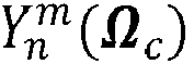

- In the following it is defined that the column elements of Y † are denoted


with n' ≤ N and n ≤ N for C ≥ (N + 1)2. - If it is assumed that the spherical microphone array has nearly uniformly distributed capsules on the surface of a sphere and that the number of capsules is greater than 0, then

becomes a valid expression. - A complete HOA processing chain for spherical microphone arrays on a rigid (stiff, fixed) sphere includes the estimation of the pressure at the capsules, the computation of the HOA coefficients and the decoding to the loudspeaker weights. The description of the microphone array in the spherical harmonics representation enables the estimation of the average spectral power at the point of origin for a given decoder. The power for the mode matching Ambisonics decoder and a simple beam forming decoder is evaluated. The estimated average power at the sweet spot is used to design an equalisation filter.
- The following section describes the decomposition of w(k) into the reference weight w ref(k), the spatial aliasing weight w alias(k) and a noise weight w noise(k). The aliasing is caused by the sampling of the continuous sound field for a finite order N and the noise simulates the spatially uncorrelated signal parts introduced for each capsule. The spatial aliasing cannot be removed for a given microphone array.
- The transfer function of an impinging plane wave for a microphone array on the surface of a rigid sphere is defined in section 2.2, equation (19) of the above-mentioned M.A.

where

- The isotropic noise signal P noise( Ω c, k) is added to simulate transducer noise, where 'isotropic' means that the noise signals of the capsules are spatially uncorrelated, which does not include the correlation in the temporal domain.
- The pressure can be separated into the pressure P ref( Ω c, kR) computed for the maximal order N of the microphone array and the pressure from the remaining orders, cf. section 7, equation (24) in the above-mentioned Rafaely "Analysis and design ..." article. The pressure from the remaining orders P alias( Ω c,kR) is called the spatial aliasing pressure because the order of the microphone array is not sufficient to reconstruct these signal components. Thus, the total pressure recorded at the capsule c is defined by:

- The Ambisonics coefficients

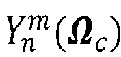

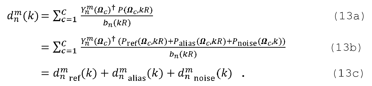
- The Ambisonics coefficients


- The optimisation uses the resulting loudspeaker weight w(k) at the point of origin. It is assumed that all speakers have the same distance to the point of .origin, so that the sum over all loudspeaker weights results in w(k). Equation (14) provides w(k) from equations (1) and (13b), where L is the number of loudspeakers:

- Equation (14b) shows that w(k) can also be separated into the three weights w ref (k), w alias(k) and w noise(k). For simplicity, the positioning error given in section 7, equation (24) of the above-mentioned Rafaely "Analysis and design ..." article is not considered here.
- In the decoding, the reference coefficients are the weights that a synthetically generated plane wave of order n would create. In the following equation (15a) the reference pressure P ref( Ω c , kR) from equation (12b) is substituted in equation (14a), whereby the pressure signals P alias( Ω c, kR) and P noise( Ω c, k) are ignored (i.e. set to zero):

- The sums over c, n' and m' can be eliminated using equation (8), so that equation (15a) can be simplified to the sum of the weights of a plane wave in the Ambisonics representation from equation (3). Thus, if the aliasing and noise signals are ignored, the theoretical coefficients of a plane wave of order N can be perfectly reconstructed from the microphone array recording.
- The resulting weight of the noise signal W noise(k) is given by

from equation (14a) and using only P noise( Ωc, k) from equation (12b). - Substituting the term of P alias( Ω c, kR) from equation (12b) in equation (14a) and ignoring the other pressure signals results in:

- The resulting aliasing weight w alias(k) cannot be simplified by the orthonormal condition from equation (8) because the index n' is greater than N.
- The simulation of the alias weight requires an Ambisonics order that represents the capsule signals with a sufficient accuracy. In section 2.2.2, equation (14) of the above-mentioned Moreau/Daniel/Bertet article an analysis of the truncation error for the Ambisonics sound field reconstruction is given. It is stated that for

a reasonable accuracy of the sound field can be obtained, where '┌•┐' denotes the rounding-up to the nearest integer. This accuracy is used for the upper frequency limit f max of the simulation. Thus, the Ambisonics order of
is used for the simulation of the aliasing pressure of each wave number. This results in an acceptable accuracy at the upper frequency limit, and the accuracy even increases for low frequencies. -
Fig. 1 shows the power of the weight components a) w ref(k), b) w noise(k) and c) w alias(k) from the resulting loudspeaker weight for a plain wave from direction Ωs = [0,0]T for a microphone array with 32 capsules on a rigid sphere (the Eigenmike from the above-mentioned Agmon/Rafaely article has been used for the simulation). The microphone capsules are uniformly distributed on the surface of the sphere with R = 4.2cm so that the orthonormal conditions are fulfilled. The maximal Ambisonics order N supported by this array is four. The mode matching processing as described in the above-mentioned M.A. Poletti article is used to obtain the decoding coefficients
- The power of the reference weight w ref(k) is constant over the entire frequency range. The resulting noise weight w noise(k) shows high power at low frequencies and decreases at higher frequencies. The noise signal or power is simulated by a normally distributed unbiased pseudo-random noise with a variance of 20dB (i.e. 20dB lower than the power of the plane wave). The aliasing noise w alias(k) can be ignored at low frequencies but increases with rising frequency, and above 10kHz exceeds the reference power. The slope of the aliasing power curve depends on the plane wave direction. However, the average tendency is consistent for all directions.
- The two error signals w noise(k) and w alias(k) distort the reference weight in different frequency ranges. Furthermore, the error signals are independent of each other. Therefore a two-step equalisation processing is proposed. In the first step, the noise signal is compensated using the method described in the European application with internal reference
PD110039 - In the first step, the mean square error between the reference weight and the distorted reference weight is minimised for all incoming plane wave directions. The weight from the aliasing signal w alias(k) is ignored because w alias(k) cannot be corrected after having been spatially band-limited by the order of the Ambisonics representation. This is equivalent to the time domain aliasing where the aliasing cannot be removed from the sampled and band-limited time signal.
- In the second step, the average power of the reconstructed weight is estimated for all plane wave directions. A filter is described below that balances the power of the reconstructed weight to the power of the reference weight. That filter equalises the power only at the sweet spot. However, the aliasing error still disrupts the sound field representation for high frequencies.
- The spatial frequency limit of a microphone array is called spatial aliasing frequency. The spatial aliasing frequency

is computed from the distance of the capsules (cf.WO 03/ 061336 A1 - The noise reduction is described in the above-mentioned European application with internal reference
PD110039 
- The parameters of transfer function Fn(k) depend on the number of microphone capsules and on the signal-to-noise ratio for the wave number k. The filter is independent of the Ambisonics decoder, which means that it is valid for three-dimensional Ambisonics decoding and directional beam forming. The SNR(k) can be obtained from the above-mentioned European application with internal reference
PD110039 - The optimised weight w'(k) is computed from

- The resulting average power of w'noise(k) is evaluated in the following section.
- The average power of the optimised weight w'(k) is obtained from its squared magnitude expectation value. The noise weight w'noise(k) is spatially uncorrelated to the weights w'ref(k) and w' alias(k) so that the noise power can be computed independently as shown in equation (23a). The power of the reference and aliasing weight are derived from equation (23b). The combination of the equations (22), (15a) and (17) results in equation (23c), where w' noise(k) is ignored in equation (22). The expansion of the squared magnitude simplifies equations (23c) and (23d) using equation (4).

- The power of the optimised error weight w' noise(k) is given in equation (23e) . The derivation of E{|w' noise(k)|2} is described in the above-mentioned European application with internal reference
PD110039 - The resulting power depends on the used decoding processing. However, for conventional three-dimensional Ambisonics decoding it is assumed that all directions are covered by the loudspeaker arrangement. In this case the coefficients with an order greater than zero are eliminated by the sum of the decoding coefficients

- This is different for beam forming of the Ambisonics representation because only sound from a specific direction is reconstructed. Here one loudspeaker is used so that all coefficients of

- This can be perfectly explained for the power of the reference weight given in equation (24) by changing the order N:

- The derivation of equation (24) is provided in the above-mentioned European application with internal reference
PD110039 
- However, for Ambisonics decoding the sum of all loudspeaker decoding coefficients

- The average power components of w'(k), obtained from the noise optimisation filter, are shown in
Fig. 3 for conventional Ambisonics decoding. Fig. 3b shows the reference + alias power, Fig. 3c shows the noise power and Fig. 3a the sum of both. The noise power is reduced to -35dB up to a frequency of 1kHz. Above 1kHz the noise power increases linearly to -10dB. The resulting noise power is smaller than P noise( Ω c, k) = -20dB up to a frequency of 8kHz. The total power is raised by 10dB above 10kHz, which is caused by the aliasing power. Above 10kHz the HOA order of the microphone array does not sufficiently describe the pressure distribution on the surface for the sphere with a radius equal to R. As a result the average power caused by the obtained Ambisonics coefficients is greater than the reference power. -
Fig. 4 shows the power components of w'(k) for decoding coefficients
- Now, an equalisation filter for the average power of w'(k) is determined. This filter strongly depends on the used decoding coefficients


- For conventional Ambisonics decoding the assumption

can be made. However, it is to be assured that the applied Ambisonics decoders will nearly fulfil that assumption. - The real-valued equalisation filter F EQ (k) is given in equation (26a). It compensates the average power of w'(k) to the reference power of w ref(k). In equation (26b) equations (23e) and (27) are used to show in equation (26b) that F EQ (k) is also a function of the SNR(k).


- The problem is that the filter F EQ (k) depends on the filter Fn(k) so that for each change of the SNR(k) both filter have to be re-designed. The computational complexity of the filter design is high due to the high Ambisonics order that is used to simulate the power of the aliasing and reference error E{|w' ref(k) + w 'alias(k)|2}. For adaptive filtering this complexity can be reduced by performing the computational complex processing only once in order to create a set of constant filter design coefficients for a given microphone array. In equations (28) the derivation of these filter coefficients is provided.

- In equation (28d) it is shown that the highly complex computation of E{|w' ref(k) + w' alias(k)|2} can be separated into the sums of n from zero to N and the dependent sum over n" from n to N. Each element of these sums is a multiplication of the filter Fn(k), its conjugated complex value, the infinite sums over n' and m' of the product of, and its conjugated complex value. The infinite sums are approximated by the finite sums running to n' = Nmax . The results of these sums give the constant filter design coefficients for each combination of n and n". These coefficients are computed once for a given array and can be stored in a look-up table for a time-variant signal-to-noise ratio adaptive filter design.

- In the practical implementation of the Ambisonics microphone array processing, the optimised Ambisonics coefficients


which includes the sum over the capsules c and an adaptive transfer function for each order n and wave number k. That sum converts the sampled pressure distribution on the surface of the sphere to the Ambisonics representation, and for wide-band signals it can be performed in the time domain. This processing step converts the time domain pressure signals P(Ω c, t) to the first Ambisonics representation
- In the second processing step the optimised transfer function

reconstructs the directional information items from the first Ambisonics representation


section 3, equation (14) of the above-mentioned Rafaely "Plane-wave decomposition ..." article, and this representation is basically used for the transmission of Ambisonics signals. Dependent on the SNR(k), the optimisation transfer function Fn(k) reduces the contribution of the higher order coefficients in order to remove the HOA coefficients that are covered by noise. The power of the reconstructed signal is equalised by the filter F EQ (k) for a known or assumed decoder processing. - The second processing step results in a convolution of

Fig. 5 , and the resulting optimised array responses for the beam forming decoder example are shown inFig. 6 . In both figures, transfer functions a)to e) correspond toAmbisonics order 0 to 4, respectively. - The processing of the coefficients


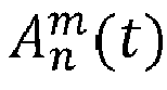
- The inventive adaptive block based Ambisonics processing is depicted in
Fig. 7 . In the upper signal path, the time domain pressure signals P(Ω c, t) of the microphone capsule signals are converted in step orstage 71 to the Ambisonics representation


stage 72. Step/stage 72 performs then the described linear filtering operation in the time domain or frequency domain in order to obtain the coefficients

stage 73 performs the estimation of the signal-to-noise ratio SNR(k) for a considered time period (i.e. block of samples). The estimation is performed in the frequency domain for a finite number of discrete wave numbers k. Thus the regarded pressure signals P(Ω c, t) have to be transformed to the frequency domain using for example an FFT. The SNR(k) value is specified by the two power signals |Pnoise(k)|2 and |P 0(k)|2. The power |Pnoise(k)|2 of the noise signal is constant for a given array and represents the noise produced by the capsules. The power |P 0(k)|2 of the plane wave is estimated from the pressure signals P(Ω c , t). The estimation is further described in section SNR estimation in the above-mentioned European application with internal referencePD110039 stage 74 in the frequency domain using equations (30), (26c), (21) and (10). The filter design can use a Wiener filter and the inverse array response orinverse transfer function 1/bn(kR). The filter implementation is then adapted to the corresponding linear filter processing in the time or frequency domain of step/stage 72. - The results of the inventive processing are discussed in the following. Therefore, the equalisation filter FEQ(k) from equation (26c) is applied to the expectation value E{|w'(k)|2}. The resulting power of E{|w'(k)|2}, the reference power E{lwref(k)|2} and the resulting noise power for the examples of the conventional Ambisonics decoding from
Fig. 3 and the beam forming fromFig. 4 are discussed. The resulting power spectra for a conventional Ambisonics decoder are depicted inFig. 8 , and for the beam forming decoder inFig. 9 , wherein curves a) to c) show |w opt|2, |w ref|2 and |w noise|2, respectively. - The power of the reference and the optimised weight are identical so that the resulting weight has a balanced frequency spectrum. At low frequencies the resulting signal-to-noise ratio at the sweet spot has increased for the conventional Ambisonics decoding and decreased for the beam forming decoding, compared to the given SNR(k) of 20db. At high frequencies the signal-to-noise ratio is equal to the given SNR(k) for both decoders. However, for the beam forming decoding the SNR at high frequencies is greater with respect to that at low frequencies, while for the Ambisonics decoder the SNR at high frequencies is smaller with respect to that at low frequencies. The smaller SNR at low frequencies of the beam forming decoder is caused by the missing higher order coefficients. In
Fig. 9 the average noise power is reduced compared to that inFig. 1 . On the other hand, the signal power has also decreased at low frequencies due to the missing higher order coefficients as discussed in section Optimisation - spectral power equalisation. As a result the distance between the signal and the noise power becomes smaller. - Furthermore, the resulting SNR strongly depends on the used decoding coefficients

- Other methods for optimised beam forming exist that minimise the resulting SNR, wherein the decoding coefficients

- The example Ambisonics decoder uses mode matching processing, where each loudspeaker weight is computed from the decoding coefficients used in the beam forming example. The decoding coefficients for the loudspeaker at Ω c are defined by

- The results show that the described optimisation is producing a balanced frequency spectrum with an increased SNR at the point of origin for a conventional Ambisonics decoder, i.e. the inventive time-variant adaptive filter design is advantageous for Ambisonics recordings. The inventive procesing can also be used for designing a time-invariant filter if the SNR of the recording can be assumed constant over the time.
- For beam forming decoders the inventive procesing can balance the resulting frequency spectrum, with the drawback of a low SNR at low frequencies. The SNR can be increased by selecting appropriate decoding coefficients that produce wider beams, or by adapting the beam width on the Ambisonics order of different frequency sub-bands.
- The invention is applicable to all spherical microphone recordings in the spherical harmonics representation, where the reproduced spectral power at the point of origin is unbalanced due to aliasing or missing spherical harmonic coefficients.
Claims (6)
- Method for processing microphone capsule signals (P(Ω c, t)) of a spherical microphone array on a rigid sphere, said method including the steps:- converting (71) said microphone capsule signals (P( Ω c, t)) representing the pressure on the surface of said microphone array to a spherical harmonics or Ambisonics representation
 - computing (73) per wave number k an estimation of the time-variant signal-to-noise ratio SNR(k) of said microphone capsule signals (P(Ωc, t)), using the average source power |P0(k)|2 of the plane wave recorded from said microphone array and the corresponding noise power |P noise( k)|2 representing the spatially uncorrelated noise produced by analog processing in said microphone array;- computing (74) per wave number k the average spatial signal power at the point of origin for a diffuse sound field, using reference, aliasing and noise signal power components,
and forming (74) the frequency response of an equalisation filter from the square root of the fraction of a given reference power and said average spatial signal power at the point of origin,
and multiplying (74) per wave number k said frequency response of said equalisation filter by the transfer function, for each order n at discrete finite wave numbers k, of a noise minimising filter derived from said signal-to-noise ratio estimation SNR(k), and by the inverse transfer function of said microphone array, in order to get an adapted transfer function Fn,array(k) ;- applying (72) said adapted transfer function Fn,array (k) to said spherical harmonics representation

- Apparatus for processing microphone capsule signals (P( Ω c, t)) of a spherical microphone array on a rigid sphere, said apparatus including:- means (71) being adapted for converting said microphone capsule signals (P(Ω c, t)) representing the pressure on the surface of said microphone array to a spherical harmonics or Ambisonics representation
 - means (73) being adapted for computing per wave number k an estimation of the time-variant signal-to-noise ratio SNR(k) of said microphone capsule signals (P(Ω c, t)), using the average source power |P o(k)|2 of the plane wave recorded from said microphone array and the corresponding noise power |P noise(k)|2 representing the spatially uncorrelated noise produced by analog processing in said microphone array;- means (74) being adapted for computing per wave number k the average spatial signal power at the point of origin for a diffuse sound field, using reference, aliasing and noise signal power components,
and for forming the frequency response of an equalisation filter from the square root of the fraction of a given reference power and said average spatial signal power at the point of origin,
and for multiplying per wave number k said frequency response of said equalisation filter by the transfer function, for each order n at discrete finite wave numbers k, of a noise minimising filter derived from said signal-to-noise ratio estimation SNR(k), and by the inverse transfer function of said microphone array, in order to get an adapted transfer function F n,array (k) ;- means (72) being adapted for applying said adapted transfer function Fn,array (k) to said spherical harmonics representation

- Method according to the method of claim 1, or apparatus according to the apparatus of claim 2, wherein said noise power |Pnoise(k)|2 is obtained in a silent environment without any sound sources so that |P o(k)|2 = 0.
- Method according to the method of claim 1 or 3, or apparatus according to the apparatus of claim 2 or 3, wherein said average source power |P o(k)|2 is estimated from the pressure P mic( Ωc, k) measured at the microphone capsules by a comparison of the expectation value of the pressure at the microphone capsules and the measured average signal power at the microphone capsules.
- Method according to the method of one of claims 1, 3 and 4, or apparatus according to the apparatus of one of claims 2 to 4, wherein said transfer function F n,array(k) of the array is determined in the frequency domain comprising:- transforming the coefficients
 - performing an inverse FFT of the product to get the time domain coefficients
or, approximation by an FIR filter in the time domain, comprising-- performing an inverse FFT;-- performing a circular shift;-- applying a tapering window to the resulting filter impulse response in order to smooth the corresponding transfer function;-- performing a convolution of the resulting filter coefficients and the coefficients
- Method according to the method of one of claims 1 and 3 to 5, or apparatus according to the apparatus of one of claims 2 to 5, wherein the transfer function of said equalisation filter is determined by

wherein E denotes an expectation value, w ref(k) is the reference weight for wave number k, w'ref(k) is the optimised reference weight for wave number k, w'alias(k) is the optimised alias weight for wave number k and w'noise(k) is the optimised noise weight for wave number k, whereby 'optimised' means noise reduced with respect to the noise arising in said spherical microphone array.
Priority Applications (7)
| Application Number | Priority Date | Filing Date | Title |
|---|---|---|---|
| EP11306472.9A EP2592846A1 (en) | 2011-11-11 | 2011-11-11 | Method and apparatus for processing signals of a spherical microphone array on a rigid sphere used for generating an Ambisonics representation of the sound field |
| KR1020147015683A KR101957544B1 (en) | 2011-11-11 | 2012-10-31 | Method and apparatus for processing signals of a spherical microphone array on a rigid sphere used for generating an ambisonics representation of the sound field |
| EP12788472.4A EP2777298B1 (en) | 2011-11-11 | 2012-10-31 | Method and apparatus for processing signals of a spherical microphone array on a rigid sphere used for generating a spherical harmonics representation or an ambisonics representation of the sound field |
| CN201280066109.4A CN104041074B (en) | 2011-11-11 | 2012-10-31 | Method and apparatus for processing signals of a spherical microphone array on a rigid sphere for producing an Ambisonics representation of a sound field |
| US14/356,265 US9420372B2 (en) | 2011-11-11 | 2012-10-31 | Method and apparatus for processing signals of a spherical microphone array on a rigid sphere used for generating an ambisonics representation of the sound field |
| PCT/EP2012/071537 WO2013068284A1 (en) | 2011-11-11 | 2012-10-31 | Method and apparatus for processing signals of a spherical microphone array on a rigid sphere used for generating an ambisonics representation of the sound field |
| JP2014540396A JP6113739B2 (en) | 2011-11-11 | 2012-10-31 | Method and apparatus for processing a spherical microphone array signal on a hard sphere used to generate an ambisonic representation of a sound field |
Applications Claiming Priority (1)
| Application Number | Priority Date | Filing Date | Title |
|---|---|---|---|
| EP11306472.9A EP2592846A1 (en) | 2011-11-11 | 2011-11-11 | Method and apparatus for processing signals of a spherical microphone array on a rigid sphere used for generating an Ambisonics representation of the sound field |
Publications (1)
| Publication Number | Publication Date |
|---|---|
| EP2592846A1 true EP2592846A1 (en) | 2013-05-15 |
Family
ID=47216219
Family Applications (2)
| Application Number | Title | Priority Date | Filing Date |
|---|---|---|---|
| EP11306472.9A Withdrawn EP2592846A1 (en) | 2011-11-11 | 2011-11-11 | Method and apparatus for processing signals of a spherical microphone array on a rigid sphere used for generating an Ambisonics representation of the sound field |
| EP12788472.4A Active EP2777298B1 (en) | 2011-11-11 | 2012-10-31 | Method and apparatus for processing signals of a spherical microphone array on a rigid sphere used for generating a spherical harmonics representation or an ambisonics representation of the sound field |
Family Applications After (1)
| Application Number | Title | Priority Date | Filing Date |
|---|---|---|---|
| EP12788472.4A Active EP2777298B1 (en) | 2011-11-11 | 2012-10-31 | Method and apparatus for processing signals of a spherical microphone array on a rigid sphere used for generating a spherical harmonics representation or an ambisonics representation of the sound field |
Country Status (6)
| Country | Link |
|---|---|
| US (1) | US9420372B2 (en) |
| EP (2) | EP2592846A1 (en) |
| JP (1) | JP6113739B2 (en) |
| KR (1) | KR101957544B1 (en) |
| CN (1) | CN104041074B (en) |
| WO (1) | WO2013068284A1 (en) |
Cited By (6)
| Publication number | Priority date | Publication date | Assignee | Title |
|---|---|---|---|---|
| WO2015101915A2 (en) | 2013-12-31 | 2015-07-09 | Distran Gmbh | Acoustic transducer array device |
| EP2988527A1 (en) | 2014-08-21 | 2016-02-24 | Patents Factory Ltd. Sp. z o.o. | System and method for detecting location of sound sources in a three-dimensional space |
| CN109275084A (en) * | 2018-09-12 | 2019-01-25 | 北京小米智能科技有限公司 | Test method, device, system, equipment and the storage medium of microphone array |
| CN111312263A (en) * | 2014-05-16 | 2020-06-19 | 高通股份有限公司 | Method and apparatus for obtaining multiple high-order stereo reverberation HOA coefficients |
| CN114928788A (en) * | 2022-04-10 | 2022-08-19 | 西北工业大学 | Sound field replay space decoding method based on sparse plane wave decomposition |
| US11962990B2 (en) | 2013-05-29 | 2024-04-16 | Qualcomm Incorporated | Reordering of foreground audio objects in the ambisonics domain |
Families Citing this family (26)
| Publication number | Priority date | Publication date | Assignee | Title |
|---|---|---|---|---|
| US10021508B2 (en) | 2011-11-11 | 2018-07-10 | Dolby Laboratories Licensing Corporation | Method and apparatus for processing signals of a spherical microphone array on a rigid sphere used for generating an ambisonics representation of the sound field |
| EP2592845A1 (en) * | 2011-11-11 | 2013-05-15 | Thomson Licensing | Method and Apparatus for processing signals of a spherical microphone array on a rigid sphere used for generating an Ambisonics representation of the sound field |
| US9466305B2 (en) | 2013-05-29 | 2016-10-11 | Qualcomm Incorporated | Performing positional analysis to code spherical harmonic coefficients |
| DK3025130T3 (en) * | 2013-07-22 | 2020-04-20 | Brueel & Kjaer Sound & Vibration Measurement As | ACOUSTIC BROADBAND HOLOGRAPHY |
| US20150127354A1 (en) * | 2013-10-03 | 2015-05-07 | Qualcomm Incorporated | Near field compensation for decomposed representations of a sound field |
| DK2863654T3 (en) * | 2013-10-17 | 2018-10-22 | Oticon As | Method for reproducing an acoustic sound field |
| EP2879408A1 (en) * | 2013-11-28 | 2015-06-03 | Thomson Licensing | Method and apparatus for higher order ambisonics encoding and decoding using singular value decomposition |
| US9922656B2 (en) | 2014-01-30 | 2018-03-20 | Qualcomm Incorporated | Transitioning of ambient higher-order ambisonic coefficients |
| US9502045B2 (en) | 2014-01-30 | 2016-11-22 | Qualcomm Incorporated | Coding independent frames of ambient higher-order ambisonic coefficients |
| US20150332682A1 (en) * | 2014-05-16 | 2015-11-19 | Qualcomm Incorporated | Spatial relation coding for higher order ambisonic coefficients |
| US10770087B2 (en) | 2014-05-16 | 2020-09-08 | Qualcomm Incorporated | Selecting codebooks for coding vectors decomposed from higher-order ambisonic audio signals |
| US9620137B2 (en) | 2014-05-16 | 2017-04-11 | Qualcomm Incorporated | Determining between scalar and vector quantization in higher order ambisonic coefficients |
| US9747910B2 (en) | 2014-09-26 | 2017-08-29 | Qualcomm Incorporated | Switching between predictive and non-predictive quantization techniques in a higher order ambisonics (HOA) framework |
| CN105072557B (en) * | 2015-08-11 | 2017-04-19 | 北京大学 | Loudspeaker environment self-adaptation calibrating method of three-dimensional surround playback system |
| JP6606784B2 (en) * | 2015-09-29 | 2019-11-20 | 本田技研工業株式会社 | Audio processing apparatus and audio processing method |
| US10206040B2 (en) | 2015-10-30 | 2019-02-12 | Essential Products, Inc. | Microphone array for generating virtual sound field |
| BR112018007276A2 (en) | 2016-03-15 | 2018-10-30 | Fraunhofer-Gesellschaft zur Förderung der angewandten Forschung e. V. | computer device, method, or program for generating a sound field description |
| WO2018053050A1 (en) * | 2016-09-13 | 2018-03-22 | VisiSonics Corporation | Audio signal processor and generator |
| WO2018064296A1 (en) * | 2016-09-29 | 2018-04-05 | Dolby Laboratories Licensing Corporation | Method, systems and apparatus for determining audio representation(s) of one or more audio sources |
| FR3060830A1 (en) * | 2016-12-21 | 2018-06-22 | Orange | SUB-BAND PROCESSING OF REAL AMBASSIC CONTENT FOR PERFECTIONAL DECODING |
| WO2018157098A1 (en) * | 2017-02-27 | 2018-08-30 | Essential Products, Inc. | Microphone array for generating virtual sound field |
| EP3625974B1 (en) | 2017-05-15 | 2020-12-23 | Dolby Laboratories Licensing Corporation | Methods, systems and apparatus for conversion of spatial audio format(s) to speaker signals |
| JP6969793B2 (en) | 2018-10-04 | 2021-11-24 | 株式会社ズーム | A / B format converter for Ambisonics, A / B format converter software, recorder, playback software |
| CN111193990B (en) * | 2020-01-06 | 2021-01-19 | 北京大学 | 3D audio system capable of resisting high-frequency spatial aliasing and implementation method |
| US11489505B2 (en) * | 2020-08-10 | 2022-11-01 | Cirrus Logic, Inc. | Methods and systems for equalization |
| CN113852903B (en) * | 2021-10-21 | 2022-05-31 | 杭州爱华智能科技有限公司 | Sound field characteristic conversion method of condenser type test microphone and condenser type test microphone system |
Citations (4)
| Publication number | Priority date | Publication date | Assignee | Title |
|---|---|---|---|---|
| US20030016835A1 (en) * | 2001-07-18 | 2003-01-23 | Elko Gary W. | Adaptive close-talking differential microphone array |
| WO2003061336A1 (en) | 2002-01-11 | 2003-07-24 | Mh Acoustics, Llc | Audio system based on at least second-order eigenbeams |
| EP1737271A1 (en) * | 2005-06-23 | 2006-12-27 | AKG Acoustics GmbH | Array microphone |
| US20100142732A1 (en) * | 2006-10-06 | 2010-06-10 | Craven Peter G | Microphone array |
Family Cites Families (5)
| Publication number | Priority date | Publication date | Assignee | Title |
|---|---|---|---|---|
| US7558393B2 (en) * | 2003-03-18 | 2009-07-07 | Miller Iii Robert E | System and method for compatible 2D/3D (full sphere with height) surround sound reproduction |
| CN101263734B (en) * | 2005-09-02 | 2012-01-25 | 丰田自动车株式会社 | Post filter for microphone array |
| GB0906269D0 (en) * | 2009-04-09 | 2009-05-20 | Ntnu Technology Transfer As | Optimal modal beamformer for sensor arrays |
| EP2592845A1 (en) * | 2011-11-11 | 2013-05-15 | Thomson Licensing | Method and Apparatus for processing signals of a spherical microphone array on a rigid sphere used for generating an Ambisonics representation of the sound field |
| US9197962B2 (en) * | 2013-03-15 | 2015-11-24 | Mh Acoustics Llc | Polyhedral audio system based on at least second-order eigenbeams |
-
2011
- 2011-11-11 EP EP11306472.9A patent/EP2592846A1/en not_active Withdrawn
-
2012
- 2012-10-31 US US14/356,265 patent/US9420372B2/en active Active
- 2012-10-31 EP EP12788472.4A patent/EP2777298B1/en active Active
- 2012-10-31 JP JP2014540396A patent/JP6113739B2/en active Active
- 2012-10-31 CN CN201280066109.4A patent/CN104041074B/en active Active
- 2012-10-31 WO PCT/EP2012/071537 patent/WO2013068284A1/en not_active Ceased
- 2012-10-31 KR KR1020147015683A patent/KR101957544B1/en active Active
Patent Citations (5)
| Publication number | Priority date | Publication date | Assignee | Title |
|---|---|---|---|---|
| US20030016835A1 (en) * | 2001-07-18 | 2003-01-23 | Elko Gary W. | Adaptive close-talking differential microphone array |
| WO2003061336A1 (en) | 2002-01-11 | 2003-07-24 | Mh Acoustics, Llc | Audio system based on at least second-order eigenbeams |
| US20100008517A1 (en) * | 2002-01-11 | 2010-01-14 | Mh Acoustics,Llc | Audio system based on at least second-order eigenbeams |
| EP1737271A1 (en) * | 2005-06-23 | 2006-12-27 | AKG Acoustics GmbH | Array microphone |
| US20100142732A1 (en) * | 2006-10-06 | 2010-06-10 | Craven Peter G | Microphone array |
Non-Patent Citations (9)
| Title |
|---|
| BOAZ RAFAELY: "Plane-wave decomposition of the sound field on a sphere by spherical convolution", J. ACOUSTICAL SOCIETY OF AMERICA, vol. 116, no. 4, 2004, pages 2149 - 2157, XP012072566, DOI: doi:10.1121/1.1792643 |
| F. ZOTTER: "Sampling Strategies for Acoustic Holography/ Holophony on the Sphere", PROCEEDINGS OF THE NAG-DAGA, 1 February 2007 (2007-02-01), Retrieved from the Internet <URL:www.mhacoustics.com> |
| JOHANN-MARKUS BATKE; FLORIAN KEILER: "Using VBAP-Derived Panning Functions for 3D Ambisonics Decoding", PROC. OF THE 2ND INTERNATIONAL SYMPOSIUM ON AMBISONICS AND SPHERICAL ACOUSTICS, 6-7 MAY 2010, PARIS, FRANCE, 6 May 2010 (2010-05-06) |
| JORG FLIEGE; ULRIKE MAIER: "A Two-Stage Approach for Computing Cubature Formulae for the Sphere", TECHNICAL REPORT, 1996 |
| M. AGMON; B. RAFAELY; J. TABRIKIAN: "Maximum Directivity Beamformer for Spherical-Aperture Microphones", IEEE WORKSHOP ON APPLCATIONS OF SIGNAL PROCESSING TO AUDIO AND ACOUSTICS WASPAA '09, PROC. IEEE INTERNATIONAL CONFERENCE ON ACOUSTICS, SPEECH, AND SIGNAL PROCESSING, 2009, pages 153 - 156, XP031575097 |
| M.A. POLETTI: "Three-Dimensional Surround Sound Systems Based on Spherical Harmonics", JOURNAL AUDIO ENGINEERING SOCIETY, vol. 53, no. LL, 2005, pages 1004 - 1025 |
| MORAG AGMON; BOAZ RAFAELY: "Beamforming for a Spherical-Aperture Microphone", IEEEI, 2008, pages 227 - 230, XP031399568 |
| MOREAU, DANIEL, BERTET: "3D Sound Field Recording with Higher Order Ambisonics- Objective Measurements and Validation of Spherical Microphone", AUDIO ENGINEERING SOCIETY, 6857, 20 May 2006 (2006-05-20) - 23 May 2006 (2006-05-23), XP002672712 * |
| Y. SHEFENG; S. HAOHAI; U.P. SVENSSON; M. XIAOCHUAN; J.M. HOVEM: "Optimal Modal Beamforming for Spherical Microphone Arrays", IEEE TRANSACTIONS ON AUDIO, SPEECH, AND LANGUAGE PROCESSING, vol. 19, no. 2, February 2011 (2011-02-01), pages 361 - 371, XP011307131, DOI: doi:10.1109/TASL.2010.2047815 |
Cited By (8)
| Publication number | Priority date | Publication date | Assignee | Title |
|---|---|---|---|---|
| US11962990B2 (en) | 2013-05-29 | 2024-04-16 | Qualcomm Incorporated | Reordering of foreground audio objects in the ambisonics domain |
| WO2015101915A2 (en) | 2013-12-31 | 2015-07-09 | Distran Gmbh | Acoustic transducer array device |
| CN111312263A (en) * | 2014-05-16 | 2020-06-19 | 高通股份有限公司 | Method and apparatus for obtaining multiple high-order stereo reverberation HOA coefficients |
| CN111312263B (en) * | 2014-05-16 | 2024-05-24 | 高通股份有限公司 | Method and device for obtaining multiple high-order ambisonic reverberation HOA coefficients |
| EP2988527A1 (en) | 2014-08-21 | 2016-02-24 | Patents Factory Ltd. Sp. z o.o. | System and method for detecting location of sound sources in a three-dimensional space |
| CN109275084A (en) * | 2018-09-12 | 2019-01-25 | 北京小米智能科技有限公司 | Test method, device, system, equipment and the storage medium of microphone array |
| CN109275084B (en) * | 2018-09-12 | 2021-01-01 | 北京小米智能科技有限公司 | Method, device, system, equipment and storage medium for testing microphone array |
| CN114928788A (en) * | 2022-04-10 | 2022-08-19 | 西北工业大学 | Sound field replay space decoding method based on sparse plane wave decomposition |
Also Published As
| Publication number | Publication date |
|---|---|
| US20140307894A1 (en) | 2014-10-16 |
| CN104041074B (en) | 2017-04-12 |
| KR101957544B1 (en) | 2019-03-12 |
| JP2014535232A (en) | 2014-12-25 |
| WO2013068284A1 (en) | 2013-05-16 |
| KR20140089601A (en) | 2014-07-15 |
| US9420372B2 (en) | 2016-08-16 |
| EP2777298B1 (en) | 2016-03-16 |
| EP2777298A1 (en) | 2014-09-17 |
| CN104041074A (en) | 2014-09-10 |
| JP6113739B2 (en) | 2017-04-12 |
Similar Documents
| Publication | Publication Date | Title |
|---|---|---|
| EP2777298B1 (en) | Method and apparatus for processing signals of a spherical microphone array on a rigid sphere used for generating a spherical harmonics representation or an ambisonics representation of the sound field | |
| EP2777297B1 (en) | Method and apparatus for processing signals of a spherical microphone array on a rigid sphere used for generating an ambisonics representation of the sound field | |
| EP3320692B1 (en) | Spatial audio processing apparatus | |
| US9113281B2 (en) | Reconstruction of a recorded sound field | |
| RU2555237C2 (en) | Device and method of decomposing input signal using downmixer | |
| KR20140138907A (en) | A method of applying a combined or hybrid sound -field control strategy | |
| Sakamoto et al. | Sound-space recording and binaural presentation system based on a 252-channel microphone array | |
| MX2013013058A (en) | Apparatus and method for generating an output signal employing a decomposer. | |
| Alexandridis et al. | Capturing and reproducing spatial audio based on a circular microphone array | |
| US10021508B2 (en) | Method and apparatus for processing signals of a spherical microphone array on a rigid sphere used for generating an ambisonics representation of the sound field | |
| WO2015159731A1 (en) | Sound field reproduction apparatus, method and program | |
| WO2016056410A1 (en) | Sound processing device, method, and program | |
| CN103181200B (en) | The estimation of Composite tone prototype | |
| WO2018053050A1 (en) | Audio signal processor and generator | |
| Do et al. | A robust sound-source separation algorithm for an adverse environment that combines MVDR-PHAT with the CASA framework | |
| Farina | Room impulse responses as temporal and spatial filters | |
| Kirkeby | Reproduction of acoustic fields | |
| Suzuki et al. | Speech Enhancement Network with Windowed Cross Attention Using Noise-Reference Microphone | |
| Mannanova et al. | An Analysis of Joint Nonlinear Spatial Filtering for Spatial Aliasing Reduction | |
| Chinaev et al. | Optimization of Feature and Loss Exponents for Lightweight DNN-based Binaural Speech Enhancement | |
| Harma | Coding principles for virtual acoustic openings | |
| Keller | Technical Report on Analysis of Directional Room Impulse Responses Recorded with Spherical Microphone Arrays | |
| Jin et al. | SUPER-RESOLUTION SOUND FIELD ANALYSES | |
| Khan | Informed algorithms for sound source separation in enclosed reverberant environments | |
| Okamoto et al. | Estimation of high-resolution sound properties for realizing an editable sound-space system |
Legal Events
| Date | Code | Title | Description |
|---|---|---|---|
| PUAI | Public reference made under article 153(3) epc to a published international application that has entered the european phase |
Free format text: ORIGINAL CODE: 0009012 |
|
| AK | Designated contracting states |
Kind code of ref document: A1 Designated state(s): AL AT BE BG CH CY CZ DE DK EE ES FI FR GB GR HR HU IE IS IT LI LT LU LV MC MK MT NL NO PL PT RO RS SE SI SK SM TR |
|
| AX | Request for extension of the european patent |
Extension state: BA ME |
|
| STAA | Information on the status of an ep patent application or granted ep patent |
Free format text: STATUS: THE APPLICATION IS DEEMED TO BE WITHDRAWN |
|
| 18D | Application deemed to be withdrawn |
Effective date: 20131116 |