EP2592832A2 - Method and apparatus for entropy encoding/decoding a transform coefficient - Google Patents
Method and apparatus for entropy encoding/decoding a transform coefficient Download PDFInfo
- Publication number
- EP2592832A2 EP2592832A2 EP11803837.1A EP11803837A EP2592832A2 EP 2592832 A2 EP2592832 A2 EP 2592832A2 EP 11803837 A EP11803837 A EP 11803837A EP 2592832 A2 EP2592832 A2 EP 2592832A2
- Authority
- EP
- European Patent Office
- Prior art keywords
- location
- coding
- information
- last significant
- transformation coefficient
- Prior art date
- Legal status (The legal status is an assumption and is not a legal conclusion. Google has not performed a legal analysis and makes no representation as to the accuracy of the status listed.)
- Granted
Links
- 238000000034 method Methods 0.000 title claims abstract description 74
- 230000009466 transformation Effects 0.000 claims abstract description 289
- 238000010586 diagram Methods 0.000 description 34
- 230000006835 compression Effects 0.000 description 6
- 238000007906 compression Methods 0.000 description 6
- 239000000284 extract Substances 0.000 description 3
- 238000013139 quantization Methods 0.000 description 3
- 238000013500 data storage Methods 0.000 description 2
- 230000000694 effects Effects 0.000 description 1
- 230000003287 optical effect Effects 0.000 description 1
- 238000005457 optimization Methods 0.000 description 1
Images


Classifications
-
- H—ELECTRICITY
- H04—ELECTRIC COMMUNICATION TECHNIQUE
- H04N—PICTORIAL COMMUNICATION, e.g. TELEVISION
- H04N19/00—Methods or arrangements for coding, decoding, compressing or decompressing digital video signals
- H04N19/60—Methods or arrangements for coding, decoding, compressing or decompressing digital video signals using transform coding
-
- H—ELECTRICITY
- H04—ELECTRIC COMMUNICATION TECHNIQUE
- H04N—PICTORIAL COMMUNICATION, e.g. TELEVISION
- H04N19/00—Methods or arrangements for coding, decoding, compressing or decompressing digital video signals
- H04N19/10—Methods or arrangements for coding, decoding, compressing or decompressing digital video signals using adaptive coding
- H04N19/102—Methods or arrangements for coding, decoding, compressing or decompressing digital video signals using adaptive coding characterised by the element, parameter or selection affected or controlled by the adaptive coding
- H04N19/119—Adaptive subdivision aspects, e.g. subdivision of a picture into rectangular or non-rectangular coding blocks
-
- H—ELECTRICITY
- H04—ELECTRIC COMMUNICATION TECHNIQUE
- H04N—PICTORIAL COMMUNICATION, e.g. TELEVISION
- H04N19/00—Methods or arrangements for coding, decoding, compressing or decompressing digital video signals
- H04N19/10—Methods or arrangements for coding, decoding, compressing or decompressing digital video signals using adaptive coding
- H04N19/102—Methods or arrangements for coding, decoding, compressing or decompressing digital video signals using adaptive coding characterised by the element, parameter or selection affected or controlled by the adaptive coding
- H04N19/129—Scanning of coding units, e.g. zig-zag scan of transform coefficients or flexible macroblock ordering [FMO]
-
- H—ELECTRICITY
- H04—ELECTRIC COMMUNICATION TECHNIQUE
- H04N—PICTORIAL COMMUNICATION, e.g. TELEVISION
- H04N19/00—Methods or arrangements for coding, decoding, compressing or decompressing digital video signals
- H04N19/10—Methods or arrangements for coding, decoding, compressing or decompressing digital video signals using adaptive coding
- H04N19/102—Methods or arrangements for coding, decoding, compressing or decompressing digital video signals using adaptive coding characterised by the element, parameter or selection affected or controlled by the adaptive coding
- H04N19/13—Adaptive entropy coding, e.g. adaptive variable length coding [AVLC] or context adaptive binary arithmetic coding [CABAC]
-
- H—ELECTRICITY
- H04—ELECTRIC COMMUNICATION TECHNIQUE
- H04N—PICTORIAL COMMUNICATION, e.g. TELEVISION
- H04N19/00—Methods or arrangements for coding, decoding, compressing or decompressing digital video signals
- H04N19/10—Methods or arrangements for coding, decoding, compressing or decompressing digital video signals using adaptive coding
- H04N19/169—Methods or arrangements for coding, decoding, compressing or decompressing digital video signals using adaptive coding characterised by the coding unit, i.e. the structural portion or semantic portion of the video signal being the object or the subject of the adaptive coding
- H04N19/17—Methods or arrangements for coding, decoding, compressing or decompressing digital video signals using adaptive coding characterised by the coding unit, i.e. the structural portion or semantic portion of the video signal being the object or the subject of the adaptive coding the unit being an image region, e.g. an object
- H04N19/176—Methods or arrangements for coding, decoding, compressing or decompressing digital video signals using adaptive coding characterised by the coding unit, i.e. the structural portion or semantic portion of the video signal being the object or the subject of the adaptive coding the unit being an image region, e.g. an object the region being a block, e.g. a macroblock
-
- H—ELECTRICITY
- H04—ELECTRIC COMMUNICATION TECHNIQUE
- H04N—PICTORIAL COMMUNICATION, e.g. TELEVISION
- H04N19/00—Methods or arrangements for coding, decoding, compressing or decompressing digital video signals
- H04N19/10—Methods or arrangements for coding, decoding, compressing or decompressing digital video signals using adaptive coding
- H04N19/169—Methods or arrangements for coding, decoding, compressing or decompressing digital video signals using adaptive coding characterised by the coding unit, i.e. the structural portion or semantic portion of the video signal being the object or the subject of the adaptive coding
- H04N19/18—Methods or arrangements for coding, decoding, compressing or decompressing digital video signals using adaptive coding characterised by the coding unit, i.e. the structural portion or semantic portion of the video signal being the object or the subject of the adaptive coding the unit being a set of transform coefficients
-
- H—ELECTRICITY
- H04—ELECTRIC COMMUNICATION TECHNIQUE
- H04N—PICTORIAL COMMUNICATION, e.g. TELEVISION
- H04N19/00—Methods or arrangements for coding, decoding, compressing or decompressing digital video signals
- H04N19/10—Methods or arrangements for coding, decoding, compressing or decompressing digital video signals using adaptive coding
- H04N19/169—Methods or arrangements for coding, decoding, compressing or decompressing digital video signals using adaptive coding characterised by the coding unit, i.e. the structural portion or semantic portion of the video signal being the object or the subject of the adaptive coding
- H04N19/184—Methods or arrangements for coding, decoding, compressing or decompressing digital video signals using adaptive coding characterised by the coding unit, i.e. the structural portion or semantic portion of the video signal being the object or the subject of the adaptive coding the unit being bits, e.g. of the compressed video stream
-
- H—ELECTRICITY
- H04—ELECTRIC COMMUNICATION TECHNIQUE
- H04N—PICTORIAL COMMUNICATION, e.g. TELEVISION
- H04N19/00—Methods or arrangements for coding, decoding, compressing or decompressing digital video signals
- H04N19/44—Decoders specially adapted therefor, e.g. video decoders which are asymmetric with respect to the encoder
-
- H—ELECTRICITY
- H04—ELECTRIC COMMUNICATION TECHNIQUE
- H04N—PICTORIAL COMMUNICATION, e.g. TELEVISION
- H04N19/00—Methods or arrangements for coding, decoding, compressing or decompressing digital video signals
- H04N19/46—Embedding additional information in the video signal during the compression process
- H04N19/463—Embedding additional information in the video signal during the compression process by compressing encoding parameters before transmission
-
- H—ELECTRICITY
- H04—ELECTRIC COMMUNICATION TECHNIQUE
- H04N—PICTORIAL COMMUNICATION, e.g. TELEVISION
- H04N19/00—Methods or arrangements for coding, decoding, compressing or decompressing digital video signals
- H04N19/60—Methods or arrangements for coding, decoding, compressing or decompressing digital video signals using transform coding
- H04N19/61—Methods or arrangements for coding, decoding, compressing or decompressing digital video signals using transform coding in combination with predictive coding
-
- H—ELECTRICITY
- H04—ELECTRIC COMMUNICATION TECHNIQUE
- H04N—PICTORIAL COMMUNICATION, e.g. TELEVISION
- H04N19/00—Methods or arrangements for coding, decoding, compressing or decompressing digital video signals
- H04N19/70—Methods or arrangements for coding, decoding, compressing or decompressing digital video signals characterised by syntax aspects related to video coding, e.g. related to compression standards
-
- H—ELECTRICITY
- H04—ELECTRIC COMMUNICATION TECHNIQUE
- H04N—PICTORIAL COMMUNICATION, e.g. TELEVISION
- H04N19/00—Methods or arrangements for coding, decoding, compressing or decompressing digital video signals
- H04N19/90—Methods or arrangements for coding, decoding, compressing or decompressing digital video signals using coding techniques not provided for in groups H04N19/10-H04N19/85, e.g. fractals
- H04N19/91—Entropy coding, e.g. variable length coding [VLC] or arithmetic coding
-
- H—ELECTRICITY
- H04—ELECTRIC COMMUNICATION TECHNIQUE
- H04N—PICTORIAL COMMUNICATION, e.g. TELEVISION
- H04N19/00—Methods or arrangements for coding, decoding, compressing or decompressing digital video signals
- H04N19/90—Methods or arrangements for coding, decoding, compressing or decompressing digital video signals using coding techniques not provided for in groups H04N19/10-H04N19/85, e.g. fractals
- H04N19/96—Tree coding, e.g. quad-tree coding
Definitions
- the present invention relates to entropy coding and decoding of transformation coefficients, and more particularly, to a method and apparatus for efficiently entropy coding and decoding information about a location of a last significant transformation coefficient in a transformation block.
- a video signal is hierarchically split into sequences, frames, slices, macro blocks, and blocks, and the block is a minimum processing unit.
- residual data of a block is obtained by performing intra-frame or inter-frame prediction.
- the residual data is compressed by performing transformation, quantization, scanning, run length coding, and entropy coding.
- a decoding process is an inverse process of the coding process. Initially, coefficients of a transformation block, which are generated in an entropy coding process, are extracted from a bit stream. Then, residual data of a block is reconfigured by performing inverse quantization and inverse transformation, and prediction information is used to reconfigure video data of the block.
- the present invention provides a method and apparatus for efficiently entropy coding and decoding information about a location of a last significant transformation coefficient in a transformation block having a large size.
- information about a location of a last significant transformation coefficient in a transformation block is coded by using its horizontal axis direction location and its vertical axis direction location in the transformation block.
- a location of a last significant transformation coefficient included in a transformation block having a large size may be efficiently represented, and information about the location of the last significant transformation coefficient may be decoded independently from a process of decoding transformation coefficients.
- a method of entropy coding transformation coefficients including determining a location of a last significant transformation coefficient having a non-zero value from among transformation coefficients included in a transformation block having a certain size, according to a certain scan order; and coding information about the location of the last significant transformation coefficient by using its horizontal axis direction location and its vertical axis direction location in the transformation block.
- a method of entropy decoding transformation coefficients including extracting information about a horizontal axis direction location and a vertical axis direction location of a last significant transformation coefficient having a non-zero value and included in a transformation block, from a received bitstream according to a certain scan order; and determining a location of the last significant transformation coefficient by decoding the information about the horizontal axis direction location and the vertical axis direction location.
- an apparatus for entropy coding transformation coefficients including an entropy coder for determining a location of a last significant transformation coefficient having a non-zero value from among transformation coefficients included in a transformation block having a certain size, according to a certain scan order, and for coding information about the location of the last significant transformation coefficient by using its horizontal axis direction location and its vertical axis direction location in the transformation block.
- an apparatus for entropy decoding transformation coefficients including an entropy decoder for extracting information about a horizontal axis direction location and a vertical axis direction location of a last significant transformation coefficient having a non-zero value and included in a transformation block, from a received bitstream according to a certain scan order, and for determining a location of the last significant transformation coefficient by decoding the information about the horizontal axis direction location and the vertical axis direction location.
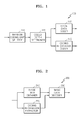
- FIG. 1 is a block diagram of an image coding apparatus 100 according to an embodiment of the present invention.
- the image coding apparatus 100 includes a maximum coding unit splitter 110, a coded depth determiner 120, an image data coder 130, and a coding information coder 140.
- the maximum coding unit splitter 110 may split a current frame or a current slice based on a maximum coding unit that is a maximum-sized coding unit.
- the current frame or the current slice may be split into at least one maximum coding unit.
- coding units may be represented by using a maximum coding unit and a depth.
- a maximum coding unit represents a coding unit having the largest size from among coding units of the current frame, and a depth represents how coding units are hierarchically reduced in size.
- coding units may be reduced in size from a maximum coding unit to a minimum coding unit, and a depth of the maximum coding unit may be defined as a minimum depth while the depth of the minimum coding unit may be defined as a maximum depth.
- a sub coding unit having a depth of k may include a plurality of sub coding units having depths greater than k.
- a compression rate may be improved if a coding unit is increased in size.
- a complicated image e.g., an image of people or buildings
- the compression rate is improved if the coding unit is reduced in size.
- different-sized maximum coding units and different maximum depths are set to different frames or slices. Since a maximum depth denotes the maximum number of times that a coding unit is reducible in size, the size of minimum coding units included in a maximum coding unit may be variably set according to a maximum depth.
- the coded depth determiner 120 determines a maximum depth.
- the maximum depth may be determined based on rate-distortion (R-D) costs.
- the maximum depth may be determined differently to each frame or slice, or to each maximum coding unit.
- Information about the determined maximum depth is output to the coding information coder 140, and image data of each maximum coding unit is output to the image data coder 130.
- the maximum depth refers to a coding unit having the smallest size in a maximum coding unit, i.e., a minimum coding unit.
- the maximum coding unit may be split into different-sized sub coding units according to different depths. Detailed descriptions thereof will be provided below with reference to FIGS. 8A and 8B .
- the different-sized sub coding units included in the maximum coding unit may be predicted or orthogonally transformed based on different-sized processing units.
- the image coding apparatus 100 may perform a plurality of processes for image coding based on various-sized and various-shaped processing units. When three processes such as prediction, orthogonal transformation, and entropy coding are performed to code image data, the same-sized processing unit may be used in all processes or different-sized processing units may be used in different processes.
- the image coding apparatus 100 may select a processing unit different from a certain coding unit in order to predict the coding unit.
- a processing unit for prediction may have a size of 2Nx2N, 2NxN, Nx2N, NxN, etc.
- motion prediction may be performed based on a processing unit having a size obtained by dividing at least one of a height and width of a coding unit in half.
- a processing unit for prediction is referred to as a 'prediction unit'.
- a prediction mode may be at least one of an intra mode, an inter mode, and a skip mode, and a certain prediction mode may be performed on only a certain-sized or certain-shaped prediction unit.
- an intra mode may be performed on only a prediction unit having a size of 2Nx2N or NxN having a square shape.
- a skip mode may be performed on only a prediction unit having a size of 2Nx2N. If a coding unit includes a plurality of prediction units, prediction may be performed on every prediction unit and a prediction unit having a least coding error may be may be selected.
- the image coding apparatus 100 may orthogonally transform image data based on a processing unit having a size different from the size of a coding unit.
- the coding unit may be orthogonally transformed based on a data unit having a size less than or equal to the size of the coding unit.
- a processing unit for orthogonal transformation is referred to as a 'transformation unit'.
- the coded depth determiner 120 may determine sub coding units included in the maximum coding unit, by using rate-distortion optimization based on a Lagrange multiplier. In other words, a split shape of the maximum coding unit into a plurality of sub coding units may be determined. Here, the plurality of sub coding units have different sizes according to depths. After that, the image data coder 130 outputs a bitstream by coding the maximum coding unit based on the split shape determined by the coded depth determiner 120.
- the coding information coder 140 codes information about a coding mode of the maximum coding unit, which is determined by the coded depth determiner 120.
- the bitstream is output by coding information about the split shape of the maximum coding unit, information about the maximum depth, and information about coding modes of sub coding units according to depths.
- the information about the coding modes of the sub coding units may include, for example, information about prediction units of the sub coding units, information about prediction modes of the prediction units, and information about transformation units of the sub coding units.
- the information about the split shape of the maximum coding unit may be information representing whether each coding unit is split. For example, when the maximum coding unit is split and coded, information representing whether the maximum coding unit is split is coded. Also, when sub coding units generated by splitting the maximum coding unit are split and coded, information representing whether each sub coding unit is split is coded. Information representing whether a coding unit is split may be flag information representing whether the coding unit is split.
- the maximum coding unit includes different-sized sub coding units and information about a coding mode of each sub coding unit has to be determined, information about at least one coding mode may be determined with respect to one maximum coding unit.
- the image coding apparatus 100 may generate sub coding units by dividing a height and width of the maximum coding unit as a depth deepens. That is, if a coding unit having a depth of k has a size of 2Nx2N, a coding unit having a depth of k+1 has a size of NxN.
- the image coding apparatus 100 may determine an optimal split shape of each maximum coding unit based on the size of the maximum coding unit and a maximum depth in consideration of image characteristics.
- the image coding apparatus 100 may determine an optimal split shape of each maximum coding unit based on the size of the maximum coding unit and a maximum depth in consideration of image characteristics.
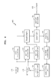
- FIG. 2 is a block diagram of an image decoding apparatus 200 according to an embodiment of the present invention.
- the image decoding apparatus 200 includes an image data obtainer 210, a coding information extractor 220, and an image data decoder 230.
- the image data obtainer 210 parses a bitstream received by the image decoding apparatus 200, and obtains and outputs image data of each maximum coding unit to the image data decoder 230.
- the image data obtainer 210 may extract information about the maximum coding unit of a current frame or slice from a header of the current frame or slice. In other words, the bitstream is split into maximum coding units to allow the image data decoder 230 to decode image data of each maximum coding unit.
- the coding information extractor 220 parses the bitstream received by the image decoding apparatus 200, and extracts from the header of the current frame information about a maximum coding unit, a maximum depth, a split shape of the maximum coding unit, and coding modes of sub coding units. The information about the split shape and the coding modes is output to the image data decoder 230.
- the information about the split shape of the maximum coding unit may include information about sub coding units included in the maximum coding unit and having different sizes according to depths. As described above in relation to FIG. 1 , the information about the split shape may be information coded and representing whether each coding unit is split (for example, flag information).
- the information about the coding modes may include, for example, information about prediction units, information about prediction modes, information about transformation units of sub coding units.
- the image data decoder 230 restores the current frame by decoding image data of each maximum coding unit based on the information extracted by the coding information extractor 220.
- the image data decoder 230 may decode sub coding units included in the maximum coding unit, based on the information about the split shape of the maximum coding unit.
- a decoding process may include an inter prediction process including intra prediction and motion compensation, and an inverse orthogonal transformation process.
- the image data decoder 230 may perform intra prediction or inter prediction based on the information about the prediction units and the information about the prediction modes of the sub coding units, in order to predict the sub coding units. Also, the image data decoder 230 may perform inverse orthogonal transformation on every sub coding unit based on the information about the transformation units of the sub coding units.
- FIG. 3 is a diagram showing hierarchical coding units according to an embodiment of the present invention.
- the hierarchical coding units may include coding units having widthxheight of 64 ⁇ 64, 32 ⁇ 32, 16 ⁇ 6, 8 ⁇ 8, and 4 ⁇ 4.
- coding units having width ⁇ height of 64 ⁇ 32, 32 ⁇ 64, 32 ⁇ 6, 16 ⁇ 32, 16 ⁇ 8, 8 ⁇ 6, 8 ⁇ 4, and 4 ⁇ 8 may also exist.
- the size of a maximum coding unit is set as 64 ⁇ 64 and a maximum depth is set as 2.
- the size of the maximum coding unit is set as 64 ⁇ 64 and the maximum depth is set as 4.
- the size of the maximum coding unit is set as 16 ⁇ 16 and the maximum depth is set as 2.
- a maximum coding size may be relatively large. Accordingly, for the image data 310 and 320 having a resolution higher than the resolution of the image data 330, the size of the maximum coding unit may be selected as 64 ⁇ 64.
- the maximum depth represents a total number of layers of the hierarchical coding units. Since the maximum depth of the image data 310 is 2, coding units 315 of the image data 310 may include a maximum coding unit having a long axis size of 64, and sub coding units having long axis sizes of 32 and 16 as a depth deepens.
- coding units 335 of the image data 330 may include maximum coding units having a long axis size of 16, and sub coding units having long axis sizes of 8 and 4 as a depth deepens.
- coding units 325 of the image data 320 may include a maximum coding unit having a long axis size of 64, and sub coding units having long axis sizes of 32, 16, 8, and 4 as a depth deepens. As such, since an image is coded based on a small sub coding unit as a depth deepens, an image including a detailed scene may be appropriately coded.
- FIG. 4 is a block diagram of an image coder 400 based on coding units, according to an embodiment of the present invention.
- An intra predictor 410 performs intra prediction on prediction units of an intra mode in a current frame 405, a motion estimator 420 and a motion compensator 425 respectively perform inter prediction and motion compensation on prediction units of an inter mode by using the current frame 405 and a reference frame 495.
- Residual values are generated based on the prediction units output from the intra predictor 410, the motion estimator 420, and the motion compensator 425, and the generated residual values pass through an orthogonal transformer 430 and a quantizer 440 so as to be output as quantized transformation coefficients.
- the quantized transformation coefficients pass through an inverse quantizer 460 and an inverse frequency transformer 470 so as to be restored as residual values, and the restored residual values post-processed through a deblocker 480 and a loop filter 490 so as to be output as the reference frame 495.
- the quantized transformation coefficients may also pass through an entropy coder 450 so as to be output as a bitstream 455.
- all components of the image coder 400 i.e., the intra predictor 410, the motion estimator 420, the motion compensator 425, the orthogonal transformer 430, the quantizer 440, the entropy coder 450, the inverse quantizer 460, the inverse frequency transformer 470, the deblocker 480, and the loop filter 490, perform image coding processes based on a maximum coding unit, sub coding units according to depths, prediction units, and transformation units.
- FIG. 5 is a block diagram of an image decoder 500 based on coding units, according to an embodiment of the present invention.
- a bitstream 505 passes through a parser 510 so as to be parsed into coded image data to be decoded, and coding information required to decode the coded image data.
- the coded image data passes through an entropy decoder 520 and an inverse quantizer 530 so as to be output as inversely quantized data, and passes through an inverse frequency transformer 540 so as to be restored as residual values.
- the residual values are added to a result of intra prediction performed by an intra predictor 550 and a result of motion compensation performed by a motion compensator 560, so as to be restored to coding units.
- the restored coding units pass through a deblocker 570 and a loop filter 580 so as to be used to decode next coding units or to predict a next frame.
- all components of the image decoder 500 i.e., the parser 510, the entropy decoder 520, the inverse quantizer 530, the inverse frequency transformer 540, the intra predictor 550, the motion compensator 560, the deblocker 570, and the loop filter 580, perform image decoding processes based on a maximum coding unit, sub coding units according to depths, prediction units, and transformation units.
- the intra predictor 550 and the motion compensator 560 determine prediction units in the sub coding units, and prediction modes in consideration of the maximum coding unit and the depths, and the inverse frequency transformer 540 performs inverse orthogonal transformation in consideration of the sizes of the transformation units.
- FIG. 6 is a diagram showing maximum coding units, sub coding units, and prediction units, according to an embodiment of the present invention.
- the image coding apparatus 100 illustrated in FIG. 1 and the image decoding apparatus 200 illustrated in FIG. 2 use hierarchical coding units in order to perform coding and decoding in consideration of image characteristics.
- a maximum coding unit and a maximum depth may be adaptively set according to image characteristics, or may be variously set according to requests of a user.
- FIG. 6 illustrates a hierarchical structure 600 of coding units in which a height and width of a maximum coding unit 610 are 64 and 64, and a maximum depth is 4.
- a depth deepens according to a vertical axis of the hierarchical structure 600 of coding units, and widths and heights of sub coding units 620, 630, 640, and 650 are reduced as the depth deepens.
- prediction units of the maximum coding unit 610 and the sub coding units 620, 630, 640, and 650 are illustrated.
- the maximum coding unit 610 has a depth of 0 and has a size, i.e., width ⁇ height, of 64 ⁇ 64.
- the depth deepens along the vertical axis, and the sub coding unit 620 having a size of 32 ⁇ 32 and a depth of 1, the sub coding unit 630 having a size of 16 ⁇ 6 and a depth of 2, the sub coding unit 640 having a size of 8 ⁇ 8 and a depth of 3, and the sub coding unit 650 having a size of 4 ⁇ 4 and a depth of 4 exist.
- the sub coding unit 650 having a size of 4 ⁇ 4 and a depth of 4 is a minimum coding unit.
- the maximum coding unit 610 having a depth of 0 may include a prediction unit 610 having a size of 64 ⁇ 64, a prediction unit 612 having a size of 64 ⁇ 32, a prediction unit 614 having a size of 32 ⁇ 64, a prediction unit 616 having a size of 32 ⁇ 32, of which sizes are equal to or less than the size of the coding unit 610, i.e., 64 ⁇ 64
- the coding unit 620 having a depth of 1 and a size of 32 ⁇ 32 may include a prediction unit 620 having a size of 32 ⁇ 32, a prediction unit 622 having a size of 32 ⁇ 6, a prediction unit 624 having a size of 16 ⁇ 32, a prediction unit 626 having a size of 16 ⁇ 6, of which sizes are equal to or less than the size of the coding unit 620, i.e., 32 ⁇ 32.
- the coding unit 630 having a depth of 2 and a size of 16 ⁇ 6 may include a prediction unit 630 having a size of 16 ⁇ 6, a prediction unit 632 having a size of 16 ⁇ 8, a prediction unit 634 having a size of 8 ⁇ 16, a prediction unit 636 having a size of 8 ⁇ 8, of which sizes are equal to or less than the size of the coding unit 630, i.e., 16 ⁇ 6.
- the coding unit 640 having a depth of 3 and a size of 8 ⁇ 8 may include a prediction unit 640 having a size of 8 ⁇ 8, a prediction unit 642 having a size of 8 ⁇ 4, a prediction unit 644 having a size of 4 ⁇ 8, a prediction unit 646 having a size of 4 ⁇ 4, of which sizes are equal to or less than the size of the coding unit 640, i.e., 8 ⁇ 8.
- the coding unit 650 having a depth of 4 and a size of 4 ⁇ 4 has a maximum depth and includes a prediction unit 650 having a size of 4 ⁇ 4.
- the coding unit 650 having the maximum depth does not inevitably need to include a prediction unit having a size equal to the size of the coding unit, and may be, like the other coding units 610, 620, 630, and 640, split for prediction into prediction units having a size less than the size of the coding unit.
- FIG. 7 is a diagram showing a coding unit and a transformation unit, according to an embodiment of the present invention.
- the image coding apparatus 100 illustrated in FIG. 1 and the image decoding apparatus 200 illustrated in FIG. 2 code a maximum coding unit or sub coding units split from and having sizes less than the size of the maximum coding unit.
- the size of a transformation unit for performing orthogonal transformation in a coding process may be selected to achieve the highest compression rate regardless of a coding unit and a prediction unit. For example, if a current coding unit 710 has a size of 64 ⁇ 64, orthogonal transformation may be performed by using a transformation unit 720 having a size of 32 ⁇ 32. Also, a transformation unit having a size greater than the size of a coding unit may be set.
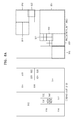
- FIGS. 8A and 8B are diagrams showing split shapes of coding units, prediction units, and transformation units, according to an embodiment of the present invention.
- FIG. 8A shows coding units and prediction units according to an embodiment of the present invention.
- FIG. 8A shows a split shape selected by the image coding apparatus 100 illustrated in FIG. 1 in order to code a maximum coding unit 810.
- the image coding apparatus 100 splits and codes the maximum coding unit 810 into various shapes, compares the coded split shapes based on R-D costs, and selects an optimal split shape. If the optimal split shape corresponds to the maximum coding unit 810, the maximum coding unit 810 may be directly coded without splitting it as illustrated in FIGS. 8A .
- the maximum coding unit 810 having a depth of 0 is split and coded into sub coding units having depths equal to or greater than 1.
- the maximum coding unit 810 is split into four sub coding units having a depth of 1, and then all or some of the sub coding units having a depth of 1 are split into sub coding units having a depth of 2.
- the top right sub coding unit and the bottom left sub coding unit are split into sub coding units having depths equal to or greater than 2.
- Some of the sub coding units having depths equal to or greater than 2 may be split into sub coding units having depths equal to or greater than 3.
- FIG. 8A shows a split shape of a prediction unit 860 regarding the maximum coding unit 810.
- the prediction unit 860 regarding the maximum coding unit 810 may be split differently from the maximum coding unit 810. In other words, a prediction unit regarding each sub coding unit may be smaller than the sub coding unit.
- a prediction unit regarding a bottom right sub coding unit 854 may be smaller than the sub coding unit 854.
- prediction units regarding some sub coding units 815, 816, 850, and 852 may be smaller than the sub coding units 815, 816, 850, and 852.
- prediction units regarding sub coding unit 822, 832, and 848 having a depth of 3 may be smaller than the sub coding unit 822, 832, and 848.
- a prediction unit may have a shape obtained by dividing each sub coding unit into two in a direction of its height or width, or a shape obtained by dividing each sub coding unit into four in a direction of its height and width.
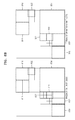
- FIG. 8B shows prediction units and transformation units according to an embodiment of the present invention.
- FIG. 8B shows a split shape of the prediction unit 860 regarding the maximum transformation unit 810 illustrated at the left side FIG. 8A
- a right side of FIG. 8B shows a split shape of a transformation unit 870 regarding the maximum transformation unit 810.
- the transformation unit 870 may be split differently from the prediction unit 860.
- a prediction unit regarding the coding unit 854 having a depth of 1 is selected as a shape obtained by dividing a height of the coding unit 854 in half
- a transformation unit regarding the coding unit 854 may be selected as a size equal to the size of the coding unit 854.
- prediction units regarding the coding units 814 and 850 having a depth of 2 are selected as shapes obtained by dividing heights of the coding units 814 and 850 in half
- transformation units regarding the coding units 814 and 850 may be selected as sizes equal to the sizes of the coding units 814 and 850.
- a transformation unit may be selected as a size less than the size of a prediction unit. For example, if a prediction unit regarding the coding unit 852 having a depth of 2 is selected as a shape obtained by dividing a width of the coding unit 852 in half, a transformation unit may be selected as a shape having a size less than the size of the prediction unit and obtained by dividing a height and width of the coding unit 852 in half. The smallest transformation unit having a size of 2 ⁇ 2 may also be set.
- a transformation unit may also be set regardless of a size of a coding unit, e.g., a size greater than the size of the coding unit.
- Entropy coding and decoding processes performed by the entropy coder 450 of the image coding apparatus 400 illustrated in FIG. 4 , and the entropy decoder 520 of the image decoding apparatus 500 illustrated in FIG. 5 will now be described in detail.
- the image coding apparatus 400 and the image decoding apparatus 500 code a maximum coding unit or sub coding units split from and having sizes less than the size of the maximum coding unit.
- the size of a transformation unit for performing orthogonal transformation in a coding process may be selected to achieve the highest compression rate regardless of a coding unit and a prediction unit. For example, if a current coding unit has a size of 64 ⁇ 64, orthogonal transformation may be performed by using a transformation unit having a size of 32 ⁇ 32. Also, a transformation unit having a size greater than the size of a coding unit may be set.
- a transformation unit to be entropy coded (hereinafter referred to as a 'transformation block') may have a relatively large size of 16 ⁇ 16, 32 ⁇ 32, 64 ⁇ 64, or 128 ⁇ 128 as well as 4 ⁇ 4 or 8 ⁇ 8 and thus a length of a run, which represents the number of continuous coefficients having a value 0 between significant transformation coefficients having non-zero values, may be increased, a large run value need to be appropriately coded.
- last_significant_coeff_flag that is a syntax element representing whether each significant transformation coefficient is a last significant transformation coefficient is entropy coded together with a significance map representing locations of significant transformation coefficients having non-zero values.
- a transformation block is entropy coded together with the significance map and last_significant_coeff_flag, it should be determined whether each significant transformation coefficient is a last significant transformation coefficient in an entropy decoding process.
- data representing entire significant transformation coefficients may not be easily and directly identified from a received bitstream. Therefore, according to embodiments of the present invention, a method of efficiently entropy coding and decoding information about a location of a last significant transformation coefficient in a transformation block having a large size is provided.
- FIG. 9 is a flowchart of a method of entropy coding transformation coefficients, according to an embodiment of the present invention.
- the entropy coder 450 determines a location of a last significant transformation coefficient from among significant transformation coefficients having non-zero values and included in a transformation block having a certain size, according to a certain scan order. In more detail, if a transformation block including transformation coefficients obtained by performing transformation and quantization processes is input, the entropy coder 450 determines significant transformation coefficients included in a transformation block according to a certain scan order, e.g., a zigzag scan order, and determines a location of a last significant transformation coefficient that is scanned lastly.
- a certain scan order e.g., a zigzag scan order
- the entropy coder 450 codes information about the location of the last significant transformation coefficient by using its horizontal axis direction location and its vertical axis direction location in the transformation block. If the last significant transformation coefficient is located at an x-th location (x is an integer equal to or greater than 0) in a horizontal axis direction, and a y-th location (y is an integer equal to or greater than 0) in a vertical axis direction, from a top left location of the transformation block, the entropy coder 450 codes the values x and y representing the location of the last significant transformation coefficient. According to a conventional technology, last_significant_coeff_flag representing whether each significant transformation coefficient is a last significant transformation coefficient is coded.
- CABAC context-adaptive binary arithmetic coding
- VLC variable length coding
- the entropy coder 450 codes level information of each significant transformation coefficient located in the transformation block. As the level information, the entropy coder 450 codes a sign vale and an absolute value of each significant transformation coefficient.
- FIG. 10 is a reference diagram for describing a process of entropy coding transformation coefficients, according to embodiments of the present invention.
- the entropy coder 450 scans transformation coefficients in a transformation block 1000 according to a zigzag scan order. It is assumed that all empty spaces in FIG. 10 represent transformation coefficients having a value '0'.
- FIG. 11 is a block diagram of an entropy coding apparatus 1100 according to an embodiment of the present invention.
- the entropy coding apparatus 1100 includes a switch 1110, a context-adaptive binary arithmetic coder (CABAC) 1120, and a variable length coder (VLC) 1130.
- CABAC context-adaptive binary arithmetic coder
- VLC variable length coder
- information about the location of the last significant transformation coefficient is coded by using CABAC or VLC.
- the switch 1110 controls information about the location of the last significant transformation coefficient, which is coded in units of a slice, a picture, and a picture group, to be output to the CABAC 1120 or the VLC 1130. Whether to code the information by using CABAC or VLC may also be determined by comparing R-D costs obtained by using CABAC and VLC.
- FIG. 12 is a block diagram of a CABAC device 1200 according to an embodiment of the present invention.
- the CABAC device 1200 mainly includes a binarizer 1210, a context modeler 1220, and a binary arithmetic coder 1230. Also, the binary arithmetic coder 1230 includes a regular coding engine 1232 and a bypass coding engine 1234.
- the binarizer 1210 transforms a horizontal axis direction location x and a vertical axis direction location y in a transformation block, which represent a location of a last significant transformation coefficient, into binary values and outputs bin strings.
- a bin represents each bit of the bin string.
- the context modeler 1220 determines a probability model required to code the currently input bins, i.e., a context, based on the input bin values or a previously coded syntax element.
- a probability model required to code the currently input bins i.e., a context
- one of previously determined contexts may be selected according to the location of the last significant transformation coefficient.
- the regular coding engine 1232 generates a bitstream by arithmetically coding the input bin values based on the probability model determined by the context modeler 1220.
- the bypass coding engine 1234 is an engine for outputting an input value without compressing it, and codes data such as pulse code modulation (PCM) data.
- PCM pulse code modulation
- FIG. 13 is a reference diagram for describing a process of selecting a context for coding information about a location of a last significant transformation coefficient, according to an embodiment of the present invention.
- the context modeler 1220 selects one of a plurality of previously prepared contexts according to the location of the last significant transformation coefficient.
- the plurality of contexts classify '0' ann ' ⁇ 1' of a binary signal into a most probable symbols (MPS) and a least probable symbols (LPS) according to the location of the last significant transformation coefficient, and set probability values of the MPS and the LPS. Which symbol of '0' and ⁇ 1' is set as an MPS or an LPS, and how to set probability values of the MPS and the LPS may be designed according to necessity.
- MPS most probable symbols
- LPS least probable symbols
- the context modeler 1220 includes three contexts having indices 0, 1, and 2 with respect to a 4 ⁇ 4 transformation block, and selects one of the three contexts having indices 0, 1, and 2 according to the location of the last significant transformation coefficient from among locations in the 4 ⁇ 4 transformation block except for a top left location.
- the context having an index 0 is selected if the last significant transformation coefficient is located at (1,0) in the 4 ⁇ 4 transformation block
- the context having an index 1 is selected if the last significant transformation coefficient is located at (0,1
- the context having an index 2 is selected if the last significant transformation coefficient is located at (1,1).
- the context modeler 1220 includes seven contexts having indices 0 to 6 with respect to an 8 ⁇ 8 transformation block, and selects one of the seven contexts having indices 0 to 6 according to the location of the last significant transformation coefficient from among locations in the 8 ⁇ 8 transformation block except for a top left location.
- the context modeler 1220 includes twelve contexts having indices 0 to 11 with respect to a 16 ⁇ 16 transformation block, and selects one of the twelve contexts having indices 0 to 11 according to the location of the last significant transformation coefficient from among locations in the 16 ⁇ 16 transformation block except for a top left location.
- the regular coding engine 1232 generates a bitstream by arithmetically coding the input bin values representing the location of the last significant transformation coefficient, based on the context determined by the context modeler 1220. For example, it is assumed that a horizontal axis direction location of the last significant transformation coefficient, i.e., X, has a value 3, and that the binarizer 1210 generates a bin string ⁇ 010' by binarizing the value 3. It is also assumed that, based on the context selected by the context modeler 1220 according to the location of the last significant transformation coefficient, an MPS is '0' having a probability value 0.8 and an LPS is ⁇ 1' having a probability value 0.2.
- the regular coding engine 1232 updates a period [0,1] into a period [0,0.8] by splitting it according to the probability value of '0' that is an initial bin for forming the bin string ⁇ 010', and updates the period [0,0.8] into a new period [0.64,0.8] according to the probability value of ⁇ 1' that is a next bin. Also, the regular coding engine 1232 updates the period [0.64,0.8] into a new period [0.64,0.768] according to the probability value of '0' that is a last bin.
- the regular coding engine 1232 outputs ⁇ 11' obtained by excluding an initial digit from ⁇ 0.11' that is a binary number of a real number 0.75 included in the period [0.64,0.768], as a code word corresponding to the value 3 representing the horizontal axis direction location of the last significant transformation coefficient. Likewise, the regular coding engine 1232 binarizes a coordinate value Y representing a vertical axis direction location of the last significant transformation coefficient, and generates a bitstream by coding the binarized coordinate value Y according to the selected context.
- the CABAC 1120 illustrated in FIG. 11 codes coded_block_flag representing whether a significant transformation coefficient having a non-zero value exists in a transformation block, and significant_coeff_flag representing a location of each significant transformation coefficient in the transformation block.
- a coding process of coded_block_flag and significant_coeff_flag may be the same as the conventional H.264 coding process. For example, referring to FIG. 14 showing a significance map 1400 corresponding to FIG.
- the significance map 1400 may be represented by setting significant_coeff_flag[i] as 1 if a transformation coefficient having an i-th scan order is a significant transformation coefficient, and setting significant_coeff_flag[i] as 0 if the transformation coefficient having an i-th scan order is 0.
- the significance map 1400 may be coded by using fifteen probability models as in H.264.
- the entropy coder 450 codes level information of each significant transformation coefficient located in the transformation block.
- FIG. 15 is a reference diagram for describing a process of coding level values of significant transformation coefficients included in the transformation block 1000 illustrated in FIG. 10 .
- the entropy coder 450 scans the transformation coefficients illustrated in FIG. 10 from the top left transformation coefficient to the last significant transformation coefficient according to a zigzag scan order and obtains one-dimensionally aligned transformation coefficients as illustrated in FIG. 15 .
- the entropy coder 450 codes the one-dimensionally aligned transformation coefficients by using a run representing the number of continuous coefficients having a value 0 between significant transformation coefficients, and a level representing a value of each significant transformation coefficient, as in conventional H.264.
- the entropy coder 450 determines the run and the level in an order opposite to the scan order, i.e., in a direction from a right side to a left side of FIG. 15 , and codes the run and the level by using a certain VLC table.
- FIG. 16 is diagram showing an example of a plurality of VLC tables VLC0 through VLC8 used according to an embodiment of the present invention.
- the entropy coder 450 may select one of the VLC tables VLC0 through VLC8 according to the location of the last significant transformation coefficient and may code the run and the level by using the selected VLC table. For example, as illustrated in FIG. 15 , VLC is performed on runs 1530, 1540, 1550, and 1560 representing the numbers of continuous transformation coefficients having a value 0 between significant transformation coefficients from a last significant transformation coefficient 1510 having a value '-1', by using the VLC table.
- a run value may be increased. For example, if a VLC table covers run values only from 0 to 63 and a run value is greater than 63, the value may not be coded by using the VLC table. Accordingly, according to an embodiment of the present invention, in consideration of a maximum run value available by a VLC table, if a transformation block has a run value greater than the maximum run value, the entropy coder 450 codes run values equal to or less than the maximum run value and then codes the other run values. For example, if the maximum run value is 63 and a run value to be coded is 70, the run value 70 is split into run values 63 and 7 and the run values 63 and 7 are separately coded as run information.
- the location (x, y) of the last significant transformation coefficient may also be coded by using VLC other than the above-described CABAC. That is, the entropy coder 450 may perform VLC on the values x and y with reference to a VLC table previously prepared according to the values x and y.
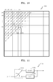
- FIG. 17 is a reference diagram for describing a method of entropy coding transformation coefficients, according to another embodiment of the present invention.
- the entropy coder 450 splits a transformation block into sub blocks having a certain size, and codes information about a location of a last significant transformation coefficient in a sub block including the last significant transformation coefficient, together with an index of the sub block.
- (Sa,b) represents a transformation coefficient in a sub block a and having a bth scan index.
- the entropy coder 450 codes (2,2) representing the location of the last significant transformation coefficient (S1,12) in the sub block 1 1771 as the information about the location of the last significant transformation coefficient in the sub block, together with a certain index representing the sub block 1 1771.
- transformation coefficients are coded by using the last significant transformation coefficient information 1010 in the transformation block 1000 (hereinafter referred to as a 'first last significant transformation coefficient') and a significant transformation coefficient 1020 previous to the first last significant transformation coefficient 1010 (hereinafter referred to as a 'second last significant transformation coefficient').
- the entropy coder 450 codes (3,4) representing the location of the second last significant transformation coefficient 1020 as described above. Then, the entropy coder 450 codes a run value between the first and second last significant transformation coefficients 1010 and 1020.
- the location of the first last significant transformation coefficient 1010 may be obtained by adding the run value between the first and second last significant transformation coefficients 1010 and 1020 to the location of the second last significant transformation coefficient 1020.
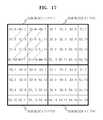
- FIGS. 18A and 18B are reference diagrams for describing a method of entropy coding transformation coefficients, according to another embodiment of the present invention.
- the entropy coder 450 may select a scan direction corresponding to one of a zigzag scan order and an inverse zigzag scan order according to in which order a last significant transformation coefficient is scanned first, that is, according to whether the last significant transformation coefficient is close to a top left location or a bottom right location of a transformation block, and may code information about a location of the last significant transformation coefficient together with an index representing the selected scan direction. For example, as illustrated in FIG. 18A , if reference numeral 1812 denotes a central location, a last significant transformation coefficient 1811 is located closer to the top left location.
- the entropy coder 450 may code information about a location of the last significant transformation coefficient 1811 together with an index (a forward scan index) representing a scanning direction from the top left location. Also, as illustrated in FIG. 18B , if reference numeral 1822 denotes a central location and a last significant transformation coefficient 1821 is located closer to the bottom right location, the entropy coder 450 may code information about a location of the last significant transformation coefficient 1821 together with an index (a backward scan index) representing a scanning direction from the bottom right location.
- a certain global run may be set and the run value may be represented by using a quotient and a remainder obtained when the run value is divided by the global run (run refinement). For example, it is assumed that the run value is 78 and the global run has a value 16. In this case, when 78 is divided by 16, a quotient is 4 and a remainder is 14. Accordingly, the run value 78 may be represented by using 16 that is the value of the global run, 4 that is the value of the quotient, and 14 that is the value of the remainder.
- the entropy coder 450 may code information about the global run, the quotient, and the remainder by using VLC or CABAC. If a coder and a decoder previously set the same global run, information about the global run may not be additionally coded.
- the entropy coder 450 may code information about a location of a last significant transformation coefficient by applying different VLC tables according to the size of a transformation block including the last significant transformation coefficient.
- FIG. 19 is a flowchart of a method of entropy decoding transformation coefficients, according to an embodiment of the present invention.
- the entropy decoder 520 extracts information about a horizontal axis direction location and a vertical axis direction location of a last significant transformation coefficient having a non-zero value and included in a transformation block, from a received bitstream according to a certain scan order.
- the last significant transformation coefficient is located at an x-th location (x is an integer equal to or greater than 0) in a horizontal axis direction, and a y-th location (y is an integer equal to or greater than 0) in a vertical axis direction, from a top left location of the transformation block
- information about a location of the last significant transformation coefficient include the values x and y.
- the entropy decoder 520 determines a location of the last significant transformation coefficient by decoding the information about the horizontal axis direction location and the vertical axis direction location.
- the entropy decoder 520 decodes the information about the location of the last significant transformation coefficient by using context-adaptive binary arithmetic decoding (CABAD) or variable length decoding (VLD) as an inverse process to the coding process performed by the entropy coder 450, and determines the location of the last significant transformation coefficient.
- the entropy decoder 520 may perform VLD on the horizontal axis direction location and the vertical axis direction location of the last significant transformation coefficient with reference to a certain VLC look-up table.
- the entropy decoder 520 may select one of a plurality of contexts according to the location of the last significant transformation coefficient, and may perform CABAD on the information about the location of the last significant transformation coefficient according to the selected context.
- the entropy decoder 520 decodes run and level information included in the bitstream, by using the location of the last significant transformation coefficient. If a length of a run is greater than a certain threshold value, the entropy decoder 520 decodes run information of a length to the threshold value, and then decodes run information of a length greater than the threshold value. As described above in relation to FIG. 16 , if the threshold value is set to code run values to 63, a run value 70 is split into run values 63 and 7 and then the run values 63 and 7 are separately coded. Thus, the entropy decoder 520 may decode the run value 70 by separately decoding and then combining the run values 63 and 7.
- FIG. 20 is a block diagram of an entropy decoding apparatus 2000 according to an embodiment of the present invention.
- the entropy decoding apparatus 2000 includes a switch 2010, a CABAD 2020, and a VLD 2030.
- the switch 2010 outputs information about coded transformation coefficients to one of the CABAD 2020 and the VLD 2030 by using coding mode information of the transformation coefficients, which is set in units of a slice, a picture, and a picture group.
- the VLD 2030 may perform VLD on a horizontal axis direction location and a vertical axis direction location of a last significant transformation coefficient with reference to a certain VLC look-up table. Also, the CABAD 2020 may select one of a plurality of contexts according to the location of the last significant transformation coefficient, and may perform CABAD on information about the location of the last significant transformation coefficient according to the selected context.
- the present invention can also be implemented as computer-readable code on a computer-readable recording medium.
- the computer-readable recording medium is any data storage device that can store data which can be thereafter read by a computer system. Examples of the computer-readable recording medium include read-only memory (ROM), random-access memory (RAM), CD-ROMs, magnetic tapes, floppy disks, optical data storage devices, etc.
- the computer-readable recording medium can also be distributed over network-coupled computer systems so that the computer-readable code is stored and executed in a distributed fashion.
Abstract
Description
- The present invention relates to entropy coding and decoding of transformation coefficients, and more particularly, to a method and apparatus for efficiently entropy coding and decoding information about a location of a last significant transformation coefficient in a transformation block.
- According to international video coding standards such as H.264 and MPEG-4, a video signal is hierarchically split into sequences, frames, slices, macro blocks, and blocks, and the block is a minimum processing unit. In a coding process, residual data of a block is obtained by performing intra-frame or inter-frame prediction. Also, the residual data is compressed by performing transformation, quantization, scanning, run length coding, and entropy coding. A decoding process is an inverse process of the coding process. Initially, coefficients of a transformation block, which are generated in an entropy coding process, are extracted from a bit stream. Then, residual data of a block is reconfigured by performing inverse quantization and inverse transformation, and prediction information is used to reconfigure video data of the block.
- The present invention provides a method and apparatus for efficiently entropy coding and decoding information about a location of a last significant transformation coefficient in a transformation block having a large size.
- According to an embodiment of the present invention, information about a location of a last significant transformation coefficient in a transformation block is coded by using its horizontal axis direction location and its vertical axis direction location in the transformation block.
- According to the present invention, a location of a last significant transformation coefficient included in a transformation block having a large size may be efficiently represented, and information about the location of the last significant transformation coefficient may be decoded independently from a process of decoding transformation coefficients.
-
-
FIG. 1 is a block diagram of an image coding apparatus according to an embodiment of the present invention. -
FIG. 2 is a block diagram of an image decoding apparatus according to an embodiment of the present invention. -
FIG. 3 is a diagram showing hierarchical coding units according to an embodiment of the present invention. -
FIG. 4 is a block diagram of an image coder based on coding units, according to an embodiment of the present invention. -
FIG. 5 is a block diagram of an image decoder based on coding units, according to an embodiment of the present invention. -
FIG. 6 is a diagram showing maximum coding units, sub coding units, and prediction units, according to an embodiment of the present invention. -
FIG. 7 is a diagram showing a coding unit and a transformation unit, according to an embodiment of the present invention. -
FIGS. 8A and8B are diagrams showing split shapes of coding units, prediction units, and transformation units, according to an embodiment of the present invention. -
FIG. 9 is a flowchart of a method of entropy coding transformation coefficients, according to an embodiment of the present invention. -
FIG. 10 is a reference diagram for describing a process of entropy coding transformation coefficients, according to embodiments of the present invention. -
FIG. 11 is a block diagram of an entropy coding apparatus according to an embodiment of the present invention. -
FIG. 12 is a block diagram of a context-adaptive binary arithmetic coding (CABAC) device according to an embodiment of the present invention. -
FIG. 13 is a reference diagram for describing a process of selecting a context for coding information about a location of a last significant transformation coefficient, according to an embodiment of the present invention. -
FIG. 14 shows a significance map corresponding toFIG. 10 . -
FIG. 15 is a reference diagram for describing a process of coding level values of significant transformation coefficients included in a transformation block illustrated inFIG. 10 . -
FIG. 16 is diagram showing an example of a plurality of variable length coding (VLC) tables used according to an embodiment of the present invention. -
FIG. 17 is a reference diagram for describing a method of entropy coding transformation coefficients, according to another embodiment of the present invention. -
FIGS. 18A and18B are reference diagrams for describing a method of entropy coding transformation coefficients, according to another embodiment of the present invention. -
FIG. 19 is a flowchart of a method of entropy decoding transformation coefficients, according to an embodiment of the present invention. -
FIG. 20 is a block diagram of an entropy decoding apparatus according to an embodiment of the present invention. - According to an aspect of the present invention, there is provided a method of entropy coding transformation coefficients, the method including determining a location of a last significant transformation coefficient having a non-zero value from among transformation coefficients included in a transformation block having a certain size, according to a certain scan order; and coding information about the location of the last significant transformation coefficient by using its horizontal axis direction location and its vertical axis direction location in the transformation block.
- According to another aspect of the present invention, there is provided a method of entropy decoding transformation coefficients, the method including extracting information about a horizontal axis direction location and a vertical axis direction location of a last significant transformation coefficient having a non-zero value and included in a transformation block, from a received bitstream according to a certain scan order; and determining a location of the last significant transformation coefficient by decoding the information about the horizontal axis direction location and the vertical axis direction location.
- According to an aspect of the present invention, there is provided an apparatus for entropy coding transformation coefficients, the apparatus including an entropy coder for determining a location of a last significant transformation coefficient having a non-zero value from among transformation coefficients included in a transformation block having a certain size, according to a certain scan order, and for coding information about the location of the last significant transformation coefficient by using its horizontal axis direction location and its vertical axis direction location in the transformation block.
- According to another aspect of the present invention, there is provided an apparatus for entropy decoding transformation coefficients, the apparatus including an entropy decoder for extracting information about a horizontal axis direction location and a vertical axis direction location of a last significant transformation coefficient having a non-zero value and included in a transformation block, from a received bitstream according to a certain scan order, and for determining a location of the last significant transformation coefficient by decoding the information about the horizontal axis direction location and the vertical axis direction location.
- Hereinafter, the present invention will be described in detail by explaining embodiments of the invention with reference to the attached drawings.
-
FIG. 1 is a block diagram of animage coding apparatus 100 according to an embodiment of the present invention. - Referring to
FIG. 1 , theimage coding apparatus 100 includes a maximumcoding unit splitter 110, a coded depth determiner 120, animage data coder 130, and acoding information coder 140. - The maximum
coding unit splitter 110 may split a current frame or a current slice based on a maximum coding unit that is a maximum-sized coding unit. The current frame or the current slice may be split into at least one maximum coding unit. - According to an embodiment of the present invention, coding units may be represented by using a maximum coding unit and a depth. As described above, a maximum coding unit represents a coding unit having the largest size from among coding units of the current frame, and a depth represents how coding units are hierarchically reduced in size. As a depth deepens, coding units may be reduced in size from a maximum coding unit to a minimum coding unit, and a depth of the maximum coding unit may be defined as a minimum depth while the depth of the minimum coding unit may be defined as a maximum depth. Since coding units are reduced in size as the depth deepens from the maximum coding unit, a sub coding unit having a depth of k may include a plurality of sub coding units having depths greater than k.
- When a frame to be coded has a large size, if an image is coded in a large unit, the image may be coded at a high image compression rate. However, if the size of a coding unit is increased and is fixed, an image may not be efficiently coded by reflecting its continuously changing characteristics.
- For example, when a flat image, e.g., an image of the sea or the sky, is coded, a compression rate may be improved if a coding unit is increased in size. However, when a complicated image, e.g., an image of people or buildings, is coded, the compression rate is improved if the coding unit is reduced in size.
- For this, according to an embodiment of the present invention, different-sized maximum coding units and different maximum depths are set to different frames or slices. Since a maximum depth denotes the maximum number of times that a coding unit is reducible in size, the size of minimum coding units included in a maximum coding unit may be variably set according to a maximum depth.
- The coded depth determiner 120 determines a maximum depth. The maximum depth may be determined based on rate-distortion (R-D) costs. The maximum depth may be determined differently to each frame or slice, or to each maximum coding unit. Information about the determined maximum depth is output to the
coding information coder 140, and image data of each maximum coding unit is output to theimage data coder 130. - The maximum depth refers to a coding unit having the smallest size in a maximum coding unit, i.e., a minimum coding unit. In other words, the maximum coding unit may be split into different-sized sub coding units according to different depths. Detailed descriptions thereof will be provided below with reference to
FIGS. 8A and8B . Also, the different-sized sub coding units included in the maximum coding unit may be predicted or orthogonally transformed based on different-sized processing units. In other words, theimage coding apparatus 100 may perform a plurality of processes for image coding based on various-sized and various-shaped processing units. When three processes such as prediction, orthogonal transformation, and entropy coding are performed to code image data, the same-sized processing unit may be used in all processes or different-sized processing units may be used in different processes. - For example, the
image coding apparatus 100 may select a processing unit different from a certain coding unit in order to predict the coding unit. - If a coding unit has a size of 2Nx2N (N is a positive integer), a processing unit for prediction may have a size of 2Nx2N, 2NxN, Nx2N, NxN, etc. In other words, motion prediction may be performed based on a processing unit having a size obtained by dividing at least one of a height and width of a coding unit in half. Hereinafter, a processing unit for prediction is referred to as a 'prediction unit'.
- A prediction mode may be at least one of an intra mode, an inter mode, and a skip mode, and a certain prediction mode may be performed on only a certain-sized or certain-shaped prediction unit. For example, an intra mode may be performed on only a prediction unit having a size of 2Nx2N or NxN having a square shape. Also, a skip mode may be performed on only a prediction unit having a size of 2Nx2N. If a coding unit includes a plurality of prediction units, prediction may be performed on every prediction unit and a prediction unit having a least coding error may be may be selected.
- Also, the
image coding apparatus 100 may orthogonally transform image data based on a processing unit having a size different from the size of a coding unit. The coding unit may be orthogonally transformed based on a data unit having a size less than or equal to the size of the coding unit. Hereinafter, a processing unit for orthogonal transformation is referred to as a 'transformation unit'. - The coded
depth determiner 120 may determine sub coding units included in the maximum coding unit, by using rate-distortion optimization based on a Lagrange multiplier. In other words, a split shape of the maximum coding unit into a plurality of sub coding units may be determined. Here, the plurality of sub coding units have different sizes according to depths. After that, theimage data coder 130 outputs a bitstream by coding the maximum coding unit based on the split shape determined by the codeddepth determiner 120. - The
coding information coder 140 codes information about a coding mode of the maximum coding unit, which is determined by the codeddepth determiner 120. The bitstream is output by coding information about the split shape of the maximum coding unit, information about the maximum depth, and information about coding modes of sub coding units according to depths. The information about the coding modes of the sub coding units may include, for example, information about prediction units of the sub coding units, information about prediction modes of the prediction units, and information about transformation units of the sub coding units. - The information about the split shape of the maximum coding unit may be information representing whether each coding unit is split. For example, when the maximum coding unit is split and coded, information representing whether the maximum coding unit is split is coded. Also, when sub coding units generated by splitting the maximum coding unit are split and coded, information representing whether each sub coding unit is split is coded. Information representing whether a coding unit is split may be flag information representing whether the coding unit is split.
- Since the maximum coding unit includes different-sized sub coding units and information about a coding mode of each sub coding unit has to be determined, information about at least one coding mode may be determined with respect to one maximum coding unit.
- The
image coding apparatus 100 may generate sub coding units by dividing a height and width of the maximum coding unit as a depth deepens. That is, if a coding unit having a depth of k has a size of 2Nx2N, a coding unit having a depth of k+1 has a size of NxN. - Accordingly, the
image coding apparatus 100 may determine an optimal split shape of each maximum coding unit based on the size of the maximum coding unit and a maximum depth in consideration of image characteristics. By variably adjusting the size of the maximum coding unit and coding an image by splitting the maximum coding unit into sub coding units having different depths in consideration of image characteristics, images having various resolutions may be efficiently coded. -
FIG. 2 is a block diagram of animage decoding apparatus 200 according to an embodiment of the present invention. - Referring to
FIG. 2 , theimage decoding apparatus 200 includes animage data obtainer 210, acoding information extractor 220, and animage data decoder 230. - The
image data obtainer 210 parses a bitstream received by theimage decoding apparatus 200, and obtains and outputs image data of each maximum coding unit to theimage data decoder 230. Theimage data obtainer 210 may extract information about the maximum coding unit of a current frame or slice from a header of the current frame or slice. In other words, the bitstream is split into maximum coding units to allow theimage data decoder 230 to decode image data of each maximum coding unit. - The
coding information extractor 220 parses the bitstream received by theimage decoding apparatus 200, and extracts from the header of the current frame information about a maximum coding unit, a maximum depth, a split shape of the maximum coding unit, and coding modes of sub coding units. The information about the split shape and the coding modes is output to theimage data decoder 230. - The information about the split shape of the maximum coding unit may include information about sub coding units included in the maximum coding unit and having different sizes according to depths. As described above in relation to
FIG. 1 , the information about the split shape may be information coded and representing whether each coding unit is split (for example, flag information). The information about the coding modes may include, for example, information about prediction units, information about prediction modes, information about transformation units of sub coding units. - The
image data decoder 230 restores the current frame by decoding image data of each maximum coding unit based on the information extracted by thecoding information extractor 220. - The
image data decoder 230 may decode sub coding units included in the maximum coding unit, based on the information about the split shape of the maximum coding unit. A decoding process may include an inter prediction process including intra prediction and motion compensation, and an inverse orthogonal transformation process. - The
image data decoder 230 may perform intra prediction or inter prediction based on the information about the prediction units and the information about the prediction modes of the sub coding units, in order to predict the sub coding units. Also, theimage data decoder 230 may perform inverse orthogonal transformation on every sub coding unit based on the information about the transformation units of the sub coding units. -
FIG. 3 is a diagram showing hierarchical coding units according to an embodiment of the present invention. - Referring to
FIG. 3 , the hierarchical coding units may include coding units having widthxheight of 64×64, 32×32, 16×6, 8×8, and 4×4. In addition to the square-shaped coding units, coding units having width×height of 64×32, 32×64, 32×6, 16×32, 16×8, 8×6, 8×4, and 4×8 may also exist. - In
FIG. 3 , to imagedata 310 having a resolution of 1920×1080, the size of a maximum coding unit is set as 64×64 and a maximum depth is set as 2. - To another
image data 320 having a resolution of 1920×1080, the size of the maximum coding unit is set as 64×64 and the maximum depth is set as 4. To imagedata 330 having a resolution of 352×288, the size of the maximum coding unit is set as 16×16 and the maximum depth is set as 2. - If a resolution is high or the amount of data is large, in order to improve a compression rate and to accurately reflect image characteristics, a maximum coding size may be relatively large. Accordingly, for the
image data image data 330, the size of the maximum coding unit may be selected as 64×64. - The maximum depth represents a total number of layers of the hierarchical coding units. Since the maximum depth of the
image data 310 is 2,coding units 315 of theimage data 310 may include a maximum coding unit having a long axis size of 64, and sub coding units having long axis sizes of 32 and 16 as a depth deepens. - Meanwhile, since the maximum depth of the
image data 330 is 2,coding units 335 of theimage data 330 may include maximum coding units having a long axis size of 16, and sub coding units having long axis sizes of 8 and 4 as a depth deepens. - Since the maximum depth of the
image data 320 is 4,coding units 325 of theimage data 320 may include a maximum coding unit having a long axis size of 64, and sub coding units having long axis sizes of 32, 16, 8, and 4 as a depth deepens. As such, since an image is coded based on a small sub coding unit as a depth deepens, an image including a detailed scene may be appropriately coded. -
FIG. 4 is a block diagram of animage coder 400 based on coding units, according to an embodiment of the present invention. - An
intra predictor 410 performs intra prediction on prediction units of an intra mode in acurrent frame 405, amotion estimator 420 and amotion compensator 425 respectively perform inter prediction and motion compensation on prediction units of an inter mode by using thecurrent frame 405 and areference frame 495. - Residual values are generated based on the prediction units output from the
intra predictor 410, themotion estimator 420, and themotion compensator 425, and the generated residual values pass through anorthogonal transformer 430 and aquantizer 440 so as to be output as quantized transformation coefficients. - The quantized transformation coefficients pass through an
inverse quantizer 460 and aninverse frequency transformer 470 so as to be restored as residual values, and the restored residual values post-processed through adeblocker 480 and aloop filter 490 so as to be output as thereference frame 495. The quantized transformation coefficients may also pass through anentropy coder 450 so as to be output as abitstream 455. - In order to code an image based on an image coding method according to an embodiment of the present invention, all components of the
image coder 400, i.e., theintra predictor 410, themotion estimator 420, themotion compensator 425, theorthogonal transformer 430, thequantizer 440, theentropy coder 450, theinverse quantizer 460, theinverse frequency transformer 470, thedeblocker 480, and theloop filter 490, perform image coding processes based on a maximum coding unit, sub coding units according to depths, prediction units, and transformation units. -
FIG. 5 is a block diagram of animage decoder 500 based on coding units, according to an embodiment of the present invention. - A
bitstream 505 passes through aparser 510 so as to be parsed into coded image data to be decoded, and coding information required to decode the coded image data. The coded image data passes through anentropy decoder 520 and aninverse quantizer 530 so as to be output as inversely quantized data, and passes through aninverse frequency transformer 540 so as to be restored as residual values. The residual values are added to a result of intra prediction performed by anintra predictor 550 and a result of motion compensation performed by amotion compensator 560, so as to be restored to coding units. The restored coding units pass through adeblocker 570 and aloop filter 580 so as to be used to decode next coding units or to predict a next frame. - In order to decode an image based on an image decoding method according to an embodiment of the present invention, all components of the
image decoder 500, i.e., theparser 510, theentropy decoder 520, theinverse quantizer 530, theinverse frequency transformer 540, theintra predictor 550, themotion compensator 560, thedeblocker 570, and theloop filter 580, perform image decoding processes based on a maximum coding unit, sub coding units according to depths, prediction units, and transformation units. - In particular, the
intra predictor 550 and themotion compensator 560 determine prediction units in the sub coding units, and prediction modes in consideration of the maximum coding unit and the depths, and theinverse frequency transformer 540 performs inverse orthogonal transformation in consideration of the sizes of the transformation units. -
FIG. 6 is a diagram showing maximum coding units, sub coding units, and prediction units, according to an embodiment of the present invention. - The
image coding apparatus 100 illustrated inFIG. 1 and theimage decoding apparatus 200 illustrated inFIG. 2 use hierarchical coding units in order to perform coding and decoding in consideration of image characteristics. A maximum coding unit and a maximum depth may be adaptively set according to image characteristics, or may be variously set according to requests of a user. -
FIG. 6 illustrates ahierarchical structure 600 of coding units in which a height and width of amaximum coding unit 610 are 64 and 64, and a maximum depth is 4. A depth deepens according to a vertical axis of thehierarchical structure 600 of coding units, and widths and heights ofsub coding units hierarchical structure 600 of coding units, prediction units of themaximum coding unit 610 and thesub coding units - The
maximum coding unit 610 has a depth of 0 and has a size, i.e., width×height, of 64×64. The depth deepens along the vertical axis, and thesub coding unit 620 having a size of 32×32 and a depth of 1, thesub coding unit 630 having a size of 16×6 and a depth of 2, thesub coding unit 640 having a size of 8×8 and a depth of 3, and thesub coding unit 650 having a size of 4×4 and a depth of 4 exist. Thesub coding unit 650 having a size of 4×4 and a depth of 4 is a minimum coding unit. - Referring to
FIG. 6 , examples of prediction units according to depths are illustrated along a horizontal axis. That is, themaximum coding unit 610 having a depth of 0 may include aprediction unit 610 having a size of 64×64, aprediction unit 612 having a size of 64×32, aprediction unit 614 having a size of 32×64, aprediction unit 616 having a size of 32×32, of which sizes are equal to or less than the size of thecoding unit 610, i.e., 64×64 - The
coding unit 620 having a depth of 1 and a size of 32×32 may include aprediction unit 620 having a size of 32×32, aprediction unit 622 having a size of 32×6, aprediction unit 624 having a size of 16×32, aprediction unit 626 having a size of 16×6, of which sizes are equal to or less than the size of thecoding unit 620, i.e., 32×32. - The
coding unit 630 having a depth of 2 and a size of 16×6 may include aprediction unit 630 having a size of 16×6, aprediction unit 632 having a size of 16×8, aprediction unit 634 having a size of 8×16, aprediction unit 636 having a size of 8×8, of which sizes are equal to or less than the size of thecoding unit 630, i.e., 16×6. - The
coding unit 640 having a depth of 3 and a size of 8×8 may include aprediction unit 640 having a size of 8×8, aprediction unit 642 having a size of 8×4, aprediction unit 644 having a size of 4×8, aprediction unit 646 having a size of 4×4, of which sizes are equal to or less than the size of thecoding unit 640, i.e., 8×8. - Lastly, the
coding unit 650 having a depth of 4 and a size of 4×4 has a maximum depth and includes aprediction unit 650 having a size of 4×4. However, thecoding unit 650 having the maximum depth does not inevitably need to include a prediction unit having a size equal to the size of the coding unit, and may be, like theother coding units -
FIG. 7 is a diagram showing a coding unit and a transformation unit, according to an embodiment of the present invention. - The
image coding apparatus 100 illustrated inFIG. 1 and theimage decoding apparatus 200 illustrated inFIG. 2 code a maximum coding unit or sub coding units split from and having sizes less than the size of the maximum coding unit. The size of a transformation unit for performing orthogonal transformation in a coding process may be selected to achieve the highest compression rate regardless of a coding unit and a prediction unit. For example, if acurrent coding unit 710 has a size of 64×64, orthogonal transformation may be performed by using atransformation unit 720 having a size of 32×32. Also, a transformation unit having a size greater than the size of a coding unit may be set. -
FIGS. 8A and8B are diagrams showing split shapes of coding units, prediction units, and transformation units, according to an embodiment of the present invention. -
FIG. 8A shows coding units and prediction units according to an embodiment of the present invention. - A left side of
FIG. 8A shows a split shape selected by theimage coding apparatus 100 illustrated inFIG. 1 in order to code amaximum coding unit 810. Theimage coding apparatus 100 splits and codes themaximum coding unit 810 into various shapes, compares the coded split shapes based on R-D costs, and selects an optimal split shape. If the optimal split shape corresponds to themaximum coding unit 810, themaximum coding unit 810 may be directly coded without splitting it as illustrated inFIGS. 8A . - Referring to the left side of
FIG. 8A , themaximum coding unit 810 having a depth of 0 is split and coded into sub coding units having depths equal to or greater than 1. Themaximum coding unit 810 is split into four sub coding units having a depth of 1, and then all or some of the sub coding units having a depth of 1 are split into sub coding units having a depth of 2. - From among the sub coding units having a depth of 1, the top right sub coding unit and the bottom left sub coding unit are split into sub coding units having depths equal to or greater than 2. Some of the sub coding units having depths equal to or greater than 2 may be split into sub coding units having depths equal to or greater than 3.
- A right side of
FIG. 8A shows a split shape of aprediction unit 860 regarding themaximum coding unit 810. - Referring to the right side of
FIG. 8A , theprediction unit 860 regarding themaximum coding unit 810 may be split differently from themaximum coding unit 810. In other words, a prediction unit regarding each sub coding unit may be smaller than the sub coding unit. - For example, from among sub coding units having a depth of 1, a prediction unit regarding a bottom right
sub coding unit 854 may be smaller than thesub coding unit 854. From amongsub coding units sub coding units sub coding units sub coding unit sub coding unit -
FIG. 8B shows prediction units and transformation units according to an embodiment of the present invention. - A left side of
FIG. 8B shows a split shape of theprediction unit 860 regarding themaximum transformation unit 810 illustrated at the left sideFIG. 8A , and a right side ofFIG. 8B shows a split shape of atransformation unit 870 regarding themaximum transformation unit 810. - Referring to the right side of
FIG. 8B , thetransformation unit 870 may be split differently from theprediction unit 860. - For example, although a prediction unit regarding the
coding unit 854 having a depth of 1 is selected as a shape obtained by dividing a height of thecoding unit 854 in half, a transformation unit regarding thecoding unit 854 may be selected as a size equal to the size of thecoding unit 854. Likewise, although prediction units regarding thecoding units coding units coding units coding units - A transformation unit may be selected as a size less than the size of a prediction unit. For example, if a prediction unit regarding the
coding unit 852 having a depth of 2 is selected as a shape obtained by dividing a width of thecoding unit 852 in half, a transformation unit may be selected as a shape having a size less than the size of the prediction unit and obtained by dividing a height and width of thecoding unit 852 in half. The smallest transformation unit having a size of 2×2 may also be set. A transformation unit may also be set regardless of a size of a coding unit, e.g., a size greater than the size of the coding unit. - Entropy coding and decoding processes performed by the
entropy coder 450 of theimage coding apparatus 400 illustrated inFIG. 4 , and theentropy decoder 520 of theimage decoding apparatus 500 illustrated inFIG. 5 will now be described in detail. - As described above in relation to
FIGS. 4 and5 , theimage coding apparatus 400 and theimage decoding apparatus 500 code a maximum coding unit or sub coding units split from and having sizes less than the size of the maximum coding unit. The size of a transformation unit for performing orthogonal transformation in a coding process may be selected to achieve the highest compression rate regardless of a coding unit and a prediction unit. For example, if a current coding unit has a size of 64×64, orthogonal transformation may be performed by using a transformation unit having a size of 32×32. Also, a transformation unit having a size greater than the size of a coding unit may be set. In a conventional coding process, e.g., H.264, residual data transformed and quantized based on a transformation unit having a relatively small size, e.g., 4×4, is entropy coded. However, according to an embodiment of the present invention, since a transformation unit to be entropy coded (hereinafter referred to as a 'transformation block') may have a relatively large size of 16×16, 32×32, 64×64, or 128×128 as well as 4×4 or 8×8 and thus a length of a run, which represents the number of continuous coefficients having avalue 0 between significant transformation coefficients having non-zero values, may be increased, a large run value need to be appropriately coded. Also, according to the conventional technology, in order to code information of coefficients included in a transformation block, last_significant_coeff_flag that is a syntax element representing whether each significant transformation coefficient is a last significant transformation coefficient is entropy coded together with a significance map representing locations of significant transformation coefficients having non-zero values. However, if a transformation block is entropy coded together with the significance map and last_significant_coeff_flag, it should be determined whether each significant transformation coefficient is a last significant transformation coefficient in an entropy decoding process. Thus, according to the conventional technology, data representing entire significant transformation coefficients may not be easily and directly identified from a received bitstream. Therefore, according to embodiments of the present invention, a method of efficiently entropy coding and decoding information about a location of a last significant transformation coefficient in a transformation block having a large size is provided. -
FIG. 9 is a flowchart of a method of entropy coding transformation coefficients, according to an embodiment of the present invention. - Referring to
FIG. 9 , inoperation 910, theentropy coder 450 determines a location of a last significant transformation coefficient from among significant transformation coefficients having non-zero values and included in a transformation block having a certain size, according to a certain scan order. In more detail, if a transformation block including transformation coefficients obtained by performing transformation and quantization processes is input, theentropy coder 450 determines significant transformation coefficients included in a transformation block according to a certain scan order, e.g., a zigzag scan order, and determines a location of a last significant transformation coefficient that is scanned lastly. - In
operation 920, theentropy coder 450 codes information about the location of the last significant transformation coefficient by using its horizontal axis direction location and its vertical axis direction location in the transformation block. If the last significant transformation coefficient is located at an x-th location (x is an integer equal to or greater than 0) in a horizontal axis direction, and a y-th location (y is an integer equal to or greater than 0) in a vertical axis direction, from a top left location of the transformation block, theentropy coder 450 codes the values x and y representing the location of the last significant transformation coefficient. According to a conventional technology, last_significant_coeff_flag representing whether each significant transformation coefficient is a last significant transformation coefficient is coded. However, according to an embodiment of the present invention, only coordinate information representing a location of a last significant transformation coefficient in a transformation block is coded. The information about the location of the last significant transformation coefficient may be coded by using a context-adaptive binary arithmetic coding (CABAC) method or a variable length coding (VLC) method. A method of coding the information about the location of the last significant transformation coefficient by using CABAC or VLC will be described below. - After the information about the location of the last significant transformation coefficient is coded, the
entropy coder 450 codes level information of each significant transformation coefficient located in the transformation block. As the level information, theentropy coder 450 codes a sign vale and an absolute value of each significant transformation coefficient. -
FIG. 10 is a reference diagram for describing a process of entropy coding transformation coefficients, according to embodiments of the present invention. - Referring to
FIG. 10 , theentropy coder 450 scans transformation coefficients in atransformation block 1000 according to a zigzag scan order. It is assumed that all empty spaces inFIG. 10 represent transformation coefficients having a value '0'. InFIG. 10 , a last significant transformation coefficient is atransformation coefficient 1010 having a value '-1'. As illustrated inFIG. 10 , the lastsignificant transformation coefficient 1010 having a value '-1' is located at a 5th location in a horizontal axis direction and a 5th location in a vertical axis direction, from a top left transformation coefficient. Accordingly, theentropy coder 450 codes values x=5 and y=5 as information about a location of the last significanttransformation coefficient information 1010. -
FIG. 11 is a block diagram of anentropy coding apparatus 1100 according to an embodiment of the present invention. - Referring to
FIG. 11 , theentropy coding apparatus 1100 includes aswitch 1110, a context-adaptive binary arithmetic coder (CABAC) 1120, and a variable length coder (VLC) 1130. - As described above in relation to
FIG. 9 , if a location of a last significant transformation coefficient is determined, information about the location of the last significant transformation coefficient is coded by using CABAC or VLC. Theswitch 1110 controls information about the location of the last significant transformation coefficient, which is coded in units of a slice, a picture, and a picture group, to be output to theCABAC 1120 or theVLC 1130. Whether to code the information by using CABAC or VLC may also be determined by comparing R-D costs obtained by using CABAC and VLC. - A method of coding the information about the location of the last significant transformation coefficient by using CABAC will now be described.
-
FIG. 12 is a block diagram of aCABAC device 1200 according to an embodiment of the present invention. - Referring to
FIG. 12 , theCABAC device 1200 mainly includes abinarizer 1210, acontext modeler 1220, and a binaryarithmetic coder 1230. Also, the binaryarithmetic coder 1230 includes aregular coding engine 1232 and abypass coding engine 1234. - The
binarizer 1210 transforms a horizontal axis direction location x and a vertical axis direction location y in a transformation block, which represent a location of a last significant transformation coefficient, into binary values and outputs bin strings. A bin represents each bit of the bin string. A method of binarizing information about the location of the last significant transformation coefficient includes various binarization methods such as unary binarization, truncated unary binarization, concatenated unary/k-th order exponential Golomb binarization, and fixed length binarization. For example, inFIG. 10 , if the location of the last significant transformation coefficient is represented as X=5 and Y=5, the values X and Y may be binarized into X=000001 and Y=000001 by using truncated unary binarization. - The information about the location of the last significant transformation coefficient, which is mapped to the binary values by the
binarizer 1210, is input to thecontext modeler 1220. Thecontext modeler 1220 determines a probability model required to code the currently input bins, i.e., a context, based on the input bin values or a previously coded syntax element. In particular, according to an embodiment of the present invention, one of previously determined contexts may be selected according to the location of the last significant transformation coefficient. - The
regular coding engine 1232 generates a bitstream by arithmetically coding the input bin values based on the probability model determined by thecontext modeler 1220. - The
bypass coding engine 1234 is an engine for outputting an input value without compressing it, and codes data such as pulse code modulation (PCM) data. -
FIG. 13 is a reference diagram for describing a process of selecting a context for coding information about a location of a last significant transformation coefficient, according to an embodiment of the present invention. - The
context modeler 1220 selects one of a plurality of previously prepared contexts according to the location of the last significant transformation coefficient. The plurality of contexts classify '0' ann ' `1' of a binary signal into a most probable symbols (MPS) and a least probable symbols (LPS) according to the location of the last significant transformation coefficient, and set probability values of the MPS and the LPS. Which symbol of '0' and `1' is set as an MPS or an LPS, and how to set probability values of the MPS and the LPS may be designed according to necessity.FIG. 13 shows contexts selected according to the location of the last significant transformation coefficient except for a top left location corresponding to a DC when transformation coefficients in a transformation block is scanned according to a zigzag scan order. Referring toFIG. 13 , thecontext modeler 1220 includes threecontexts having indices contexts having indices index 0 is selected if the last significant transformation coefficient is located at (1,0) in the 4×4 transformation block, the context having anindex 1 is selected if the last significant transformation coefficient is located at (0,1 and the context having anindex 2 is selected if the last significant transformation coefficient is located at (1,1). Likewise, thecontext modeler 1220 includes sevencontexts having indices 0 to 6 with respect to an 8×8 transformation block, and selects one of the sevencontexts having indices 0 to 6 according to the location of the last significant transformation coefficient from among locations in the 8×8 transformation block except for a top left location. Similarly, thecontext modeler 1220 includes twelvecontexts having indices 0 to 11 with respect to a 16×16 transformation block, and selects one of the twelvecontexts having indices 0 to 11 according to the location of the last significant transformation coefficient from among locations in the 16×16 transformation block except for a top left location. - The
regular coding engine 1232 generates a bitstream by arithmetically coding the input bin values representing the location of the last significant transformation coefficient, based on the context determined by thecontext modeler 1220. For example, it is assumed that a horizontal axis direction location of the last significant transformation coefficient, i.e., X, has avalue 3, and that thebinarizer 1210 generates a bin string `010' by binarizing thevalue 3. It is also assumed that, based on the context selected by thecontext modeler 1220 according to the location of the last significant transformation coefficient, an MPS is '0' having a probability value 0.8 and an LPS is `1' having a probability value 0.2. Theregular coding engine 1232 updates a period [0,1] into a period [0,0.8] by splitting it according to the probability value of '0' that is an initial bin for forming the bin string `010', and updates the period [0,0.8] into a new period [0.64,0.8] according to the probability value of `1' that is a next bin. Also, theregular coding engine 1232 updates the period [0.64,0.8] into a new period [0.64,0.768] according to the probability value of '0' that is a last bin. Theregular coding engine 1232 outputs `11' obtained by excluding an initial digit from `0.11' that is a binary number of a real number 0.75 included in the period [0.64,0.768], as a code word corresponding to thevalue 3 representing the horizontal axis direction location of the last significant transformation coefficient. Likewise, theregular coding engine 1232 binarizes a coordinate value Y representing a vertical axis direction location of the last significant transformation coefficient, and generates a bitstream by coding the binarized coordinate value Y according to the selected context. - In addition to the above-described information about the location of the last significant transformation coefficient, the
CABAC 1120 illustrated inFIG. 11 codes coded_block_flag representing whether a significant transformation coefficient having a non-zero value exists in a transformation block, and significant_coeff_flag representing a location of each significant transformation coefficient in the transformation block. A coding process of coded_block_flag and significant_coeff_flag may be the same as the conventional H.264 coding process. For example, referring toFIG. 14 showing asignificance map 1400 corresponding toFIG. 10 , thesignificance map 1400 may be represented by setting significant_coeff_flag[i] as 1 if a transformation coefficient having an i-th scan order is a significant transformation coefficient, and setting significant_coeff_flag[i] as 0 if the transformation coefficient having an i-th scan order is 0. Thesignificance map 1400 may be coded by using fifteen probability models as in H.264. - After the information about the location of the last significant transformation coefficient is coded, the
entropy coder 450 codes level information of each significant transformation coefficient located in the transformation block. -
FIG. 15 is a reference diagram for describing a process of coding level values of significant transformation coefficients included in thetransformation block 1000 illustrated inFIG. 10 . - Referring to
FIGS. 10 and15 , theentropy coder 450 scans the transformation coefficients illustrated inFIG. 10 from the top left transformation coefficient to the last significant transformation coefficient according to a zigzag scan order and obtains one-dimensionally aligned transformation coefficients as illustrated inFIG. 15 . - The
entropy coder 450 codes the one-dimensionally aligned transformation coefficients by using a run representing the number of continuous coefficients having avalue 0 between significant transformation coefficients, and a level representing a value of each significant transformation coefficient, as in conventional H.264. In more detail, theentropy coder 450 determines the run and the level in an order opposite to the scan order, i.e., in a direction from a right side to a left side ofFIG. 15 , and codes the run and the level by using a certain VLC table. -
FIG. 16 is diagram showing an example of a plurality of VLC tables VLC0 through VLC8 used according to an embodiment of the present invention. Theentropy coder 450 may select one of the VLC tables VLC0 through VLC8 according to the location of the last significant transformation coefficient and may code the run and the level by using the selected VLC table. For example, as illustrated inFIG. 15 , VLC is performed onruns value 0 between significant transformation coefficients from a lastsignificant transformation coefficient 1510 having a value '-1', by using the VLC table. - Since a transformation block according to an embodiment of the present invention may have a large size equal to or greater than 16×6, a run value may be increased. For example, if a VLC table covers run values only from 0 to 63 and a run value is greater than 63, the value may not be coded by using the VLC table. Accordingly, according to an embodiment of the present invention, in consideration of a maximum run value available by a VLC table, if a transformation block has a run value greater than the maximum run value, the
entropy coder 450 codes run values equal to or less than the maximum run value and then codes the other run values. For example, if the maximum run value is 63 and a run value to be coded is 70, the run value 70 is split into run values 63 and 7 and the run values 63 and 7 are separately coded as run information. - According to another embodiment of the present invention, the location (x, y) of the last significant transformation coefficient may also be coded by using VLC other than the above-described CABAC. That is, the
entropy coder 450 may perform VLC on the values x and y with reference to a VLC table previously prepared according to the values x and y. -
FIG. 17 is a reference diagram for describing a method of entropy coding transformation coefficients, according to another embodiment of the present invention. - According to the current embodiment, the
entropy coder 450 splits a transformation block into sub blocks having a certain size, and codes information about a location of a last significant transformation coefficient in a sub block including the last significant transformation coefficient, together with an index of the sub block. InFIG. 17 , it is assumed that (Sa,b) represents a transformation coefficient in a sub block a and having a bth scan index. Referring toFIG. 17 , if it is assumed that the last significant transformation coefficient is (S1,12) in asub block 1 1771, theentropy coder 450 codes (2,2) representing the location of the last significant transformation coefficient (S1,12) in thesub block 1 1771 as the information about the location of the last significant transformation coefficient in the sub block, together with a certain index representing thesub block 1 1771. - Referring back to
FIG. 10 , according to another embodiment of the present invention, transformation coefficients are coded by using the last significanttransformation coefficient information 1010 in the transformation block 1000 (hereinafter referred to as a 'first last significant transformation coefficient') and asignificant transformation coefficient 1020 previous to the first last significant transformation coefficient 1010 (hereinafter referred to as a 'second last significant transformation coefficient'). In more detail, theentropy coder 450 codes (3,4) representing the location of the second lastsignificant transformation coefficient 1020 as described above. Then, theentropy coder 450 codes a run value between the first and second lastsignificant transformation coefficients significant transformation coefficient 1020 is known, the location of the first lastsignificant transformation coefficient 1010 may be obtained by adding the run value between the first and second lastsignificant transformation coefficients significant transformation coefficient 1020. -
FIGS. 18A and18B are reference diagrams for describing a method of entropy coding transformation coefficients, according to another embodiment of the present invention. - The
entropy coder 450 may select a scan direction corresponding to one of a zigzag scan order and an inverse zigzag scan order according to in which order a last significant transformation coefficient is scanned first, that is, according to whether the last significant transformation coefficient is close to a top left location or a bottom right location of a transformation block, and may code information about a location of the last significant transformation coefficient together with an index representing the selected scan direction. For example, as illustrated inFIG. 18A , ifreference numeral 1812 denotes a central location, a lastsignificant transformation coefficient 1811 is located closer to the top left location. In this case, theentropy coder 450 may code information about a location of the lastsignificant transformation coefficient 1811 together with an index (a forward scan index) representing a scanning direction from the top left location. Also, as illustrated inFIG. 18B , ifreference numeral 1822 denotes a central location and a lastsignificant transformation coefficient 1821 is located closer to the bottom right location, theentropy coder 450 may code information about a location of the lastsignificant transformation coefficient 1821 together with an index (a backward scan index) representing a scanning direction from the bottom right location. - According to another embodiment of the present invention, in order to code a run value, a certain global run may be set and the run value may be represented by using a quotient and a remainder obtained when the run value is divided by the global run (run refinement). For example, it is assumed that the run value is 78 and the global run has a
value 16. In this case, when 78 is divided by 16, a quotient is 4 and a remainder is 14. Accordingly, the run value 78 may be represented by using 16 that is the value of the global run, 4 that is the value of the quotient, and 14 that is the value of the remainder. Theentropy coder 450 may code information about the global run, the quotient, and the remainder by using VLC or CABAC. If a coder and a decoder previously set the same global run, information about the global run may not be additionally coded. - Also, according to another embodiment of the present invention, the
entropy coder 450 may code information about a location of a last significant transformation coefficient by applying different VLC tables according to the size of a transformation block including the last significant transformation coefficient. -
FIG. 19 is a flowchart of a method of entropy decoding transformation coefficients, according to an embodiment of the present invention. - Referring to
FIG. 19 , inoperation 1910, theentropy decoder 520 extracts information about a horizontal axis direction location and a vertical axis direction location of a last significant transformation coefficient having a non-zero value and included in a transformation block, from a received bitstream according to a certain scan order. As described above in relation toFIG. 9 , if the last significant transformation coefficient is located at an x-th location (x is an integer equal to or greater than 0) in a horizontal axis direction, and a y-th location (y is an integer equal to or greater than 0) in a vertical axis direction, from a top left location of the transformation block, information about a location of the last significant transformation coefficient include the values x and y. - In
operation 1920, theentropy decoder 520 determines a location of the last significant transformation coefficient by decoding the information about the horizontal axis direction location and the vertical axis direction location. Theentropy decoder 520 decodes the information about the location of the last significant transformation coefficient by using context-adaptive binary arithmetic decoding (CABAD) or variable length decoding (VLD) as an inverse process to the coding process performed by theentropy coder 450, and determines the location of the last significant transformation coefficient. In more detail, theentropy decoder 520 may perform VLD on the horizontal axis direction location and the vertical axis direction location of the last significant transformation coefficient with reference to a certain VLC look-up table. Also, theentropy decoder 520 may select one of a plurality of contexts according to the location of the last significant transformation coefficient, and may perform CABAD on the information about the location of the last significant transformation coefficient according to the selected context. - In
operation 1930, theentropy decoder 520 decodes run and level information included in the bitstream, by using the location of the last significant transformation coefficient. If a length of a run is greater than a certain threshold value, theentropy decoder 520 decodes run information of a length to the threshold value, and then decodes run information of a length greater than the threshold value. As described above in relation toFIG. 16 , if the threshold value is set to code run values to 63, a run value 70 is split into run values 63 and 7 and then the run values 63 and 7 are separately coded. Thus, theentropy decoder 520 may decode the run value 70 by separately decoding and then combining the run values 63 and 7. -
FIG. 20 is a block diagram of anentropy decoding apparatus 2000 according to an embodiment of the present invention. - Referring to
FIG. 20 , theentropy decoding apparatus 2000 includes aswitch 2010, aCABAD 2020, and aVLD 2030. - The
switch 2010 outputs information about coded transformation coefficients to one of theCABAD 2020 and theVLD 2030 by using coding mode information of the transformation coefficients, which is set in units of a slice, a picture, and a picture group. - The
VLD 2030 may perform VLD on a horizontal axis direction location and a vertical axis direction location of a last significant transformation coefficient with reference to a certain VLC look-up table. Also, theCABAD 2020 may select one of a plurality of contexts according to the location of the last significant transformation coefficient, and may perform CABAD on information about the location of the last significant transformation coefficient according to the selected context. - The present invention can also be implemented as computer-readable code on a computer-readable recording medium. The computer-readable recording medium is any data storage device that can store data which can be thereafter read by a computer system. Examples of the computer-readable recording medium include read-only memory (ROM), random-access memory (RAM), CD-ROMs, magnetic tapes, floppy disks, optical data storage devices, etc. The computer-readable recording medium can also be distributed over network-coupled computer systems so that the computer-readable code is stored and executed in a distributed fashion.
- While the present invention has been particularly shown and described with reference to exemplary embodiments thereof, it will be understood by one of ordinary skill in the art that various changes in form and details may be made therein without departing from the spirit and scope of the invention as defined by the following claims. Therefore, the scope of the invention is defined not by the detailed description of the invention but by the following claims, and all differences within the scope will be construed as being included in the present invention.
Claims (15)
- A method of entropy coding transformation coefficients, the method comprising:determining a location of a last significant transformation coefficient having a non-zero value from among transformation coefficients included in a transformation block having a certain size, according to a certain scan order; andcoding information about the location of the last significant transformation coefficient by using its horizontal axis direction location and its vertical axis direction location in the transformation block.
- The method of claim 1, wherein the coding of the information about the location of the last significant transformation coefficient comprises, if the last significant transformation coefficient is located at an x-th location (x is an integer equal to or greater than 0) in a horizontal axis direction, and a y-th location (y is an integer equal to or greater than 0) in a vertical axis direction, from a top left location of the transformation block, coding the values x and y representing the location of the last significant transformation coefficient.
- The method of claim 1, wherein the coding of the information about the location of the last significant transformation coefficient comprises performing variable length coding (VLC) on information about the horizontal axis direction location and the vertical axis direction location of the last significant transformation coefficient.
- The method of claim 3, wherein the coding of the information about the location of the last significant transformation coefficient comprises performing VLC on the information about the horizontal axis direction location and the vertical axis direction location of the last significant transformation coefficient with reference to a certain VLC look-up table.
- The method of claim 3, further comprising coding run information representing the number of continuous coefficients having a value 0 between significant transformation coefficients and level information of the significant transformation coefficients, according to an inverse scan order,
wherein the coding of the run information comprises, if a length of a run is greater than a certain threshold value, coding run information of a length to the threshold value and then coding run information of a length greater than the threshold value. - The method of claim 1, wherein the coding of the information about the location of the last significant transformation coefficient further comprises:binarizing information about the horizontal axis direction location and the vertical axis direction location of the last significant transformation coefficient;selecting a context used to code the binarized information; andperforming context-adaptive binary arithmetic coding (CABAC) on the binarized information according to the selected context.
- The method of claim 6, wherein the selecting of the context comprises selecting one of a previously determined contexts according to the location of the last significant transformation coefficient.
- A method of entropy decoding transformation coefficients, the method comprising:extracting information about a horizontal axis direction location and a vertical axis direction location of a last significant transformation coefficient having a non-zero value and included in a transformation block, from a received bitstream according to a certain scan order; anddetermining a location of the last significant transformation coefficient by decoding the information about the horizontal axis direction location and the vertical axis direction location.
- The method of claim 8, wherein the determining of the location of the last significant transformation coefficient comprises, if the last significant transformation coefficient is located at an x-th location (x is an integer equal to or greater than 0) in a horizontal axis direction, and a y-th location (y is an integer equal to or greater than 0) in a vertical axis direction, from a top left location of the transformation block, decoding the values x and y representing the location of the last significant transformation coefficient.
- The method of claim 8, wherein the determining of the location of the last significant transformation coefficient comprises performing variable length decoding (VLD) on the information about the horizontal axis direction location and the vertical axis direction location of the last significant transformation coefficient.
- The method of claim 10, wherein the determining of the location of the last significant transformation coefficient comprises
performing VLD on the information about the horizontal axis direction location and the vertical axis direction location of the last significant transformation coefficient with reference to a certain variable length coding (VLC) look-up table. - The method of claim 10, further comprising decoding run information representing the number of continuous coefficients having a value 0 between significant transformation coefficients and level information of the significant transformation coefficients, according to an inverse scan order,
wherein the decoding of the run information comprises, if a length of a run is greater than a certain threshold value, decoding run information of a length to the threshold value and then decoding run information of a length greater than the threshold value. - The method of claim 8, wherein the determining of the location of the last significant transformation coefficient further comprises:selecting a context used to decode binarized information about the horizontal axis direction location and the vertical axis direction location of the last significant transformation coefficient; andperforming context-adaptive binary arithmetic decoding (CABAD) on the binarized information according to the selected context.
- The method of claim 13, wherein the selecting of the context comprises selecting one of a previously determined contexts according to the location of the last significant transformation coefficient.
- The method of claim 13, further comprising decoding a significance map representing locations of significant transformation coefficients in the transformation block, and level values of the significant transformation coefficients.
Priority Applications (20)
| Application Number | Priority Date | Filing Date | Title |
|---|---|---|---|
| DK16180225.1T DK3104616T3 (en) | 2010-07-09 | 2011-07-08 | Apparatus for entropy decoding transformation coefficients |
| DK16180227.7T DK3104617T3 (en) | 2010-07-09 | 2011-07-08 | Method of entropy decoding transformation coefficients |
| NO16180227A NO3104617T3 (en) | 2010-07-09 | 2011-07-08 | |
| RS20160751A RS55152B1 (en) | 2010-07-09 | 2011-07-08 | Method and apparatus for entropy encoding/decoding a transform coefficient |
| EP16180225.1A EP3104616B1 (en) | 2010-07-09 | 2011-07-08 | Apparatus for entropy decoding transform coefficients |
| DK16180224.4T DK3101901T3 (en) | 2010-07-09 | 2011-07-08 | Method of entropy decoding transformation coefficients |
| EP16180227.7A EP3104617B1 (en) | 2010-07-09 | 2011-07-08 | Method for entropy decoding transform coefficients |
| EP17193482.1A EP3293976B1 (en) | 2010-07-09 | 2011-07-08 | Method for entropy encoding transform coefficients |
| EP16180222.8A EP3101900B1 (en) | 2010-07-09 | 2011-07-08 | Apparatus for entropy decoding a transform coefficient |
| EP16180224.4A EP3101901B1 (en) | 2010-07-09 | 2011-07-08 | Method for entropy decoding transform coefficients |
| PL16180225T PL3104616T3 (en) | 2010-07-09 | 2011-07-08 | Apparatus for entropy decoding transform coefficients |
| PL16180224T PL3101901T3 (en) | 2010-07-09 | 2011-07-08 | Method for entropy decoding transform coefficients |
| SI201130957A SI2592832T1 (en) | 2010-07-09 | 2011-07-08 | Method and apparatus for entropy encoding/decoding a transform coefficient |
| DK16180222.8T DK3101900T3 (en) | 2010-07-09 | 2011-07-08 | Apparatus for entropy decoding a transformation coefficient |
| PL16180227T PL3104617T3 (en) | 2010-07-09 | 2011-07-08 | Method for entropy decoding transform coefficients |
| HRP20161151TT HRP20161151T1 (en) | 2010-07-09 | 2016-09-07 | Method and apparatus for entropy encoding/decoding a transform coefficient |
| CY20171100924T CY1119264T1 (en) | 2010-07-09 | 2017-08-31 | METHOD FOR DECOMPOSITION OF TRANSFORMATION RATES ENTRY |
| CY20171100926T CY1119267T1 (en) | 2010-07-09 | 2017-08-31 | DEVICE FOR DECOMPOSITION OF TRANSFORMATION COLLABORATORS |
| CY20171100925T CY1119266T1 (en) | 2010-07-09 | 2017-08-31 | DEVICE FOR ENTERTAINMENT UNDERSTANDING A TRANSFORMATION COLLABORATOR |
| CY20181100012T CY1119732T1 (en) | 2010-07-09 | 2018-01-04 | METHOD FOR DECOMPOSITION OF TRANSFORMATION RATES ENTRY |
Applications Claiming Priority (2)
| Application Number | Priority Date | Filing Date | Title |
|---|---|---|---|
| US36284410P | 2010-07-09 | 2010-07-09 | |
| PCT/KR2011/005034 WO2012005551A2 (en) | 2010-07-09 | 2011-07-08 | Method and apparatus for entropy encoding/decoding a transform coefficient |
Related Child Applications (9)
| Application Number | Title | Priority Date | Filing Date |
|---|---|---|---|
| EP16180227.7A Division-Into EP3104617B1 (en) | 2010-07-09 | 2011-07-08 | Method for entropy decoding transform coefficients |
| EP16180227.7A Division EP3104617B1 (en) | 2010-07-09 | 2011-07-08 | Method for entropy decoding transform coefficients |
| EP16180222.8A Division EP3101900B1 (en) | 2010-07-09 | 2011-07-08 | Apparatus for entropy decoding a transform coefficient |
| EP16180222.8A Division-Into EP3101900B1 (en) | 2010-07-09 | 2011-07-08 | Apparatus for entropy decoding a transform coefficient |
| EP16180224.4A Division-Into EP3101901B1 (en) | 2010-07-09 | 2011-07-08 | Method for entropy decoding transform coefficients |
| EP16180224.4A Division EP3101901B1 (en) | 2010-07-09 | 2011-07-08 | Method for entropy decoding transform coefficients |
| EP17193482.1A Division EP3293976B1 (en) | 2010-07-09 | 2011-07-08 | Method for entropy encoding transform coefficients |
| EP16180225.1A Division EP3104616B1 (en) | 2010-07-09 | 2011-07-08 | Apparatus for entropy decoding transform coefficients |
| EP16180225.1A Division-Into EP3104616B1 (en) | 2010-07-09 | 2011-07-08 | Apparatus for entropy decoding transform coefficients |
Publications (3)
| Publication Number | Publication Date |
|---|---|
| EP2592832A2 true EP2592832A2 (en) | 2013-05-15 |
| EP2592832A4 EP2592832A4 (en) | 2015-08-12 |
| EP2592832B1 EP2592832B1 (en) | 2016-09-07 |
Family
ID=45441682
Family Applications (6)
| Application Number | Title | Priority Date | Filing Date |
|---|---|---|---|
| EP11803837.1A Active EP2592832B1 (en) | 2010-07-09 | 2011-07-08 | Method and apparatus for entropy encoding/decoding a transform coefficient |
| EP16180227.7A Active EP3104617B1 (en) | 2010-07-09 | 2011-07-08 | Method for entropy decoding transform coefficients |
| EP16180225.1A Active EP3104616B1 (en) | 2010-07-09 | 2011-07-08 | Apparatus for entropy decoding transform coefficients |
| EP17193482.1A Active EP3293976B1 (en) | 2010-07-09 | 2011-07-08 | Method for entropy encoding transform coefficients |
| EP16180222.8A Active EP3101900B1 (en) | 2010-07-09 | 2011-07-08 | Apparatus for entropy decoding a transform coefficient |
| EP16180224.4A Active EP3101901B1 (en) | 2010-07-09 | 2011-07-08 | Method for entropy decoding transform coefficients |
Family Applications After (5)
| Application Number | Title | Priority Date | Filing Date |
|---|---|---|---|
| EP16180227.7A Active EP3104617B1 (en) | 2010-07-09 | 2011-07-08 | Method for entropy decoding transform coefficients |
| EP16180225.1A Active EP3104616B1 (en) | 2010-07-09 | 2011-07-08 | Apparatus for entropy decoding transform coefficients |
| EP17193482.1A Active EP3293976B1 (en) | 2010-07-09 | 2011-07-08 | Method for entropy encoding transform coefficients |
| EP16180222.8A Active EP3101900B1 (en) | 2010-07-09 | 2011-07-08 | Apparatus for entropy decoding a transform coefficient |
| EP16180224.4A Active EP3101901B1 (en) | 2010-07-09 | 2011-07-08 | Method for entropy decoding transform coefficients |
Country Status (27)
| Country | Link |
|---|---|
| US (4) | US9414063B2 (en) |
| EP (6) | EP2592832B1 (en) |
| JP (4) | JP5873084B2 (en) |
| KR (8) | KR101733794B1 (en) |
| CN (5) | CN105847811B (en) |
| AU (5) | AU2011274680B2 (en) |
| BR (4) | BR112013000558B1 (en) |
| CA (2) | CA2804939C (en) |
| CY (5) | CY1117981T1 (en) |
| DK (5) | DK3101901T3 (en) |
| ES (5) | ES2653160T3 (en) |
| HR (5) | HRP20161151T1 (en) |
| HU (5) | HUE030382T2 (en) |
| LT (5) | LT3101901T (en) |
| MX (1) | MX2013000344A (en) |
| MY (5) | MY184224A (en) |
| NO (1) | NO3104617T3 (en) |
| PH (4) | PH12015500943B1 (en) |
| PL (5) | PL3101900T3 (en) |
| PT (5) | PT2592832T (en) |
| RS (5) | RS56253B1 (en) |
| RU (4) | RU2530341C1 (en) |
| SG (2) | SG195591A1 (en) |
| SI (5) | SI3101900T1 (en) |
| SM (1) | SMT201600310B (en) |
| WO (1) | WO2012005551A2 (en) |
| ZA (4) | ZA201300699B (en) |
Cited By (3)
| Publication number | Priority date | Publication date | Assignee | Title |
|---|---|---|---|---|
| US9491469B2 (en) | 2011-06-28 | 2016-11-08 | Qualcomm Incorporated | Coding of last significant transform coefficient |
| WO2020151753A1 (en) * | 2019-01-25 | 2020-07-30 | Mediatek Inc. | Method and apparatus of transform coefficient coding with tb-level constraint |
| US11330272B2 (en) | 2010-12-22 | 2022-05-10 | Qualcomm Incorporated | Using a most probable scanning order to efficiently code scanning order information for a video block in video coding |
Families Citing this family (36)
| Publication number | Priority date | Publication date | Assignee | Title |
|---|---|---|---|---|
| JP2011259205A (en) | 2010-06-09 | 2011-12-22 | Sony Corp | Image decoding device, image encoding device, and method and program thereof |
| EP2592832B1 (en) * | 2010-07-09 | 2016-09-07 | Samsung Electronics Co., Ltd | Method and apparatus for entropy encoding/decoding a transform coefficient |
| US10091529B2 (en) * | 2010-07-09 | 2018-10-02 | Samsung Electronics Co., Ltd. | Method and apparatus for entropy encoding/decoding a transform coefficient |
| MX353197B (en) * | 2010-11-26 | 2018-01-05 | Nec Corp | Image encoding device, image decoding device, image encoding method, image decoding method, and program. |
| US8976861B2 (en) * | 2010-12-03 | 2015-03-10 | Qualcomm Incorporated | Separately coding the position of a last significant coefficient of a video block in video coding |
| US9042440B2 (en) | 2010-12-03 | 2015-05-26 | Qualcomm Incorporated | Coding the position of a last significant coefficient within a video block based on a scanning order for the block in video coding |
| US10992958B2 (en) | 2010-12-29 | 2021-04-27 | Qualcomm Incorporated | Video coding using mapped transforms and scanning modes |
| US20120230418A1 (en) | 2011-03-08 | 2012-09-13 | Qualcomm Incorporated | Coding of transform coefficients for video coding |
| US9106913B2 (en) | 2011-03-08 | 2015-08-11 | Qualcomm Incorporated | Coding of transform coefficients for video coding |
| CN105554510B (en) | 2011-06-28 | 2019-06-28 | 三星电子株式会社 | The method and apparatus that video is decoded |
| US9756360B2 (en) * | 2011-07-19 | 2017-09-05 | Qualcomm Incorporated | Coefficient scanning in video coding |
| US9154792B2 (en) * | 2011-11-08 | 2015-10-06 | Qualcomm Incorporated | Progressive coding of position of last significant coefficient |
| AU2012200319B2 (en) | 2012-01-19 | 2015-11-26 | Canon Kabushiki Kaisha | Method, apparatus and system for encoding and decoding the significance map for residual coefficients of a transform unit |
| CN107302368B (en) * | 2012-01-20 | 2020-07-28 | Ge视频压缩有限责任公司 | Apparatus for decoding a plurality of transform coefficients having a transform coefficient level from a data stream |
| US9565435B2 (en) * | 2012-02-04 | 2017-02-07 | Google Technology Holdings LLC | Devices and methods for context reduction in last significant coefficient position coding |
| KR20130116754A (en) * | 2012-04-16 | 2013-10-24 | 주식회사 팬택 | Methods of entropy coding and entropy decoding and apparatuses using the same |
| MY182016A (en) | 2012-07-02 | 2021-01-18 | Samsung Electronics Co Ltd | Method and apparatus for entropy coding video and method and apparatus for entropy decoding video |
| WO2014110651A1 (en) * | 2013-01-16 | 2014-07-24 | Blackberry Limited | Transform coefficient coding for context-adaptive binary entropy coding of video |
| CN104104958B (en) * | 2013-04-08 | 2017-08-25 | 联发科技(新加坡)私人有限公司 | Picture decoding method and its picture decoding apparatus |
| US9215464B2 (en) * | 2013-09-19 | 2015-12-15 | Blackberry Limited | Coding position data for the last non-zero transform coefficient in a coefficient group |
| KR102250088B1 (en) | 2013-10-24 | 2021-05-10 | 삼성전자주식회사 | Method and Apparatus for decoding video stream |
| EP3293975A4 (en) * | 2015-09-08 | 2018-10-10 | Samsung Electronics Co., Ltd. | Device and method for entropy encoding and decoding |
| WO2017041271A1 (en) * | 2015-09-10 | 2017-03-16 | Mediatek Singapore Pte. Ltd. | Efficient context modeling for coding a block of data |
| CN108353179A (en) * | 2015-09-10 | 2018-07-31 | 三星电子株式会社 | Encoding device, decoding device and its coding method and coding/decoding method |
| EP3270594A1 (en) * | 2016-07-15 | 2018-01-17 | Thomson Licensing | Method and apparatus for advanced cabac context adaptation for last coefficient coding |
| WO2018030294A1 (en) * | 2016-08-10 | 2018-02-15 | パナソニック インテレクチュアル プロパティ コーポレーション オブ アメリカ | Encoding device, decoding device, encoding method and decoding method |
| US10244261B2 (en) * | 2017-01-26 | 2019-03-26 | Google Llc | Transform coefficient coding using level maps |
| US11240536B2 (en) * | 2017-04-13 | 2022-02-01 | Lg Electronics Inc. | Method and device for entropy encoding, decoding video signal |
| CN108881909A (en) * | 2017-05-09 | 2018-11-23 | 富士通株式会社 | Scanning sequency generation method and scanning sequency generating device |
| WO2019078693A1 (en) * | 2017-10-20 | 2019-04-25 | 에스케이텔레콤 주식회사 | Apparatus and method for image encoding or decoding |
| CN109874012B (en) * | 2017-12-04 | 2020-09-11 | 北京金山云网络技术有限公司 | Video coding method, encoder, electronic device and medium |
| US20220046246A1 (en) * | 2019-03-12 | 2022-02-10 | Lg Electronics Inc. | Transform-based image coding method and device therefor |
| WO2020256482A1 (en) * | 2019-06-19 | 2020-12-24 | 엘지전자 주식회사 | Transform-based image coding method and device therefor |
| CN110708552B (en) * | 2019-08-27 | 2021-12-31 | 杭州海康威视数字技术股份有限公司 | Decoding method, encoding method and device |
| WO2021062019A1 (en) * | 2019-09-24 | 2021-04-01 | Beijing Dajia Internet Information Technology Co., Ltd. | Lossless coding modes for video coding |
| CN113489980B (en) * | 2021-08-13 | 2022-10-25 | 北京大学深圳研究生院 | Method and equipment for entropy coding and entropy decoding of point cloud attribute transformation coefficient |
Family Cites Families (22)
| Publication number | Priority date | Publication date | Assignee | Title |
|---|---|---|---|---|
| JPH11331612A (en) | 1998-05-19 | 1999-11-30 | Canon Inc | Picture processor, its method and storage medium |
| JP2003153228A (en) * | 2001-11-15 | 2003-05-23 | Sony Corp | Image encoding apparatus and image decoding apparatus |
| DK1487113T3 (en) * | 2002-05-02 | 2006-11-20 | Fraunhofer Ges Forschung | Encoding and decoding transformation coefficients in image or video encoders |
| US7379608B2 (en) | 2003-12-04 | 2008-05-27 | Fraunhofer-Gesellschaft Zur Foerderung Der Angewandten Forschung, E.V. | Arithmetic coding for transforming video and picture data units |
| JP2007043651A (en) | 2005-07-05 | 2007-02-15 | Ntt Docomo Inc | Dynamic image encoding device, dynamic image encoding method, dynamic image encoding program, dynamic image decoding device, dynamic image decoding method, and dynamic image decoding program |
| US20080130989A1 (en) | 2005-07-22 | 2008-06-05 | Mitsubishi Electric Corporation | Image encoder and image decoder, image encoding method and image decoding method, image encoding program and image decoding program, and computer readable recording medium recorded with image encoding program and computer readable recording medium recorded with image decoding program |
| US8599925B2 (en) | 2005-08-12 | 2013-12-03 | Microsoft Corporation | Efficient coding and decoding of transform blocks |
| KR100772870B1 (en) * | 2005-12-12 | 2007-11-02 | 삼성전자주식회사 | Method and apparatus for encoding and decoding video signal using coefficient's property which composes FGS layer's block |
| JP4379444B2 (en) | 2006-07-26 | 2009-12-09 | ソニー株式会社 | Decoding method, decoding method program, recording medium storing decoding method program, and decoding apparatus |
| CN101321060B (en) * | 2007-06-07 | 2011-06-08 | 管海明 | Method and system for encoding and decoding digital message |
| WO2009037828A1 (en) * | 2007-09-21 | 2009-03-26 | Panasonic Corporation | Image encoding device and image decoding device |
| KR20090097013A (en) * | 2008-03-10 | 2009-09-15 | 삼성전자주식회사 | Apparatus of encoding image and apparatus of decoding image |
| KR101375668B1 (en) | 2008-03-17 | 2014-03-18 | 삼성전자주식회사 | Method and apparatus for encoding transformed coefficients and method and apparatus for decoding transformed coefficients |
| KR20090129926A (en) | 2008-06-13 | 2009-12-17 | 삼성전자주식회사 | Method and apparatus for image encoding by dynamic unit grouping, and method and apparatus for image decoding by dynamic unit grouping |
| EP2154894A1 (en) * | 2008-08-15 | 2010-02-17 | Thomson Licensing | Video coding with coding of the locations of significant coefficients in a block of coefficients |
| US8406307B2 (en) * | 2008-08-22 | 2013-03-26 | Microsoft Corporation | Entropy coding/decoding of hierarchically organized data |
| US7804428B2 (en) * | 2008-11-10 | 2010-09-28 | Apple Inc. | System and method for compressing a stream of integer-valued data |
| KR101457894B1 (en) * | 2009-10-28 | 2014-11-05 | 삼성전자주식회사 | Method and apparatus for encoding image, and method and apparatus for decoding image |
| EP2592832B1 (en) * | 2010-07-09 | 2016-09-07 | Samsung Electronics Co., Ltd | Method and apparatus for entropy encoding/decoding a transform coefficient |
| US9042440B2 (en) | 2010-12-03 | 2015-05-26 | Qualcomm Incorporated | Coding the position of a last significant coefficient within a video block based on a scanning order for the block in video coding |
| US8976861B2 (en) * | 2010-12-03 | 2015-03-10 | Qualcomm Incorporated | Separately coding the position of a last significant coefficient of a video block in video coding |
| CN103597838B (en) * | 2011-04-15 | 2017-03-29 | 黑莓有限公司 | The method and apparatus that the position of last position coefficient of efficiency is encoded and decoded |
-
2011
- 2011-07-08 EP EP11803837.1A patent/EP2592832B1/en active Active
- 2011-07-08 SI SI201131284T patent/SI3101900T1/en unknown
- 2011-07-08 KR KR1020110067996A patent/KR101733794B1/en not_active Application Discontinuation
- 2011-07-08 SG SG2013078647A patent/SG195591A1/en unknown
- 2011-07-08 RU RU2013105483/08A patent/RU2530341C1/en active
- 2011-07-08 PT PT118038371T patent/PT2592832T/en unknown
- 2011-07-08 DK DK16180224.4T patent/DK3101901T3/en active
- 2011-07-08 PL PL16180222T patent/PL3101900T3/en unknown
- 2011-07-08 DK DK11803837.1T patent/DK2592832T3/en active
- 2011-07-08 RS RS20170865A patent/RS56253B1/en unknown
- 2011-07-08 ES ES16180224.4T patent/ES2653160T3/en active Active
- 2011-07-08 EP EP16180227.7A patent/EP3104617B1/en active Active
- 2011-07-08 ES ES11803837.1T patent/ES2590705T3/en active Active
- 2011-07-08 HU HUE11803837A patent/HUE030382T2/en unknown
- 2011-07-08 SI SI201130957A patent/SI2592832T1/en unknown
- 2011-07-08 NO NO16180227A patent/NO3104617T3/no unknown
- 2011-07-08 BR BR112013000558-0A patent/BR112013000558B1/en active IP Right Grant
- 2011-07-08 RS RS20171173A patent/RS56577B1/en unknown
- 2011-07-08 SG SG10201703211YA patent/SG10201703211YA/en unknown
- 2011-07-08 ES ES16180222.8T patent/ES2648315T3/en active Active
- 2011-07-08 AU AU2011274680A patent/AU2011274680B2/en active Active
- 2011-07-08 MY MYPI2015000870A patent/MY184224A/en unknown
- 2011-07-08 WO PCT/KR2011/005034 patent/WO2012005551A2/en active Application Filing
- 2011-07-08 PL PL16180225T patent/PL3104616T3/en unknown
- 2011-07-08 LT LTEP16180224.4T patent/LT3101901T/en unknown
- 2011-07-08 ES ES16180227.7T patent/ES2648061T3/en active Active
- 2011-07-08 EP EP16180225.1A patent/EP3104616B1/en active Active
- 2011-07-08 SI SI201131283T patent/SI3104616T1/en unknown
- 2011-07-08 CA CA2804939A patent/CA2804939C/en active Active
- 2011-07-08 CN CN201610305424.8A patent/CN105847811B/en active Active
- 2011-07-08 LT LTEP16180227.7T patent/LT3104617T/en unknown
- 2011-07-08 MY MYPI2015000862A patent/MY184097A/en unknown
- 2011-07-08 CN CN201180043638.8A patent/CN103098469B/en active Active
- 2011-07-08 PT PT161802228T patent/PT3101900T/en unknown
- 2011-07-08 RS RS20170864A patent/RS56250B1/en unknown
- 2011-07-08 CN CN201610305655.9A patent/CN105791846B/en active Active
- 2011-07-08 HU HUE16180227A patent/HUE036472T2/en unknown
- 2011-07-08 PL PL11803837.1T patent/PL2592832T3/en unknown
- 2011-07-08 BR BR122021004665-4A patent/BR122021004665B1/en active IP Right Grant
- 2011-07-08 DK DK16180225.1T patent/DK3104616T3/en active
- 2011-07-08 LT LTEP11803837.1T patent/LT2592832T/en unknown
- 2011-07-08 LT LTEP16180225.1T patent/LT3104616T/en unknown
- 2011-07-08 PL PL16180227T patent/PL3104617T3/en unknown
- 2011-07-08 BR BR122020013774-6A patent/BR122020013774B1/en active IP Right Grant
- 2011-07-08 MY MYPI2015000864A patent/MY184131A/en unknown
- 2011-07-08 DK DK16180222.8T patent/DK3101900T3/en active
- 2011-07-08 PT PT161802277T patent/PT3104617T/en unknown
- 2011-07-08 JP JP2013519577A patent/JP5873084B2/en active Active
- 2011-07-08 CN CN201610304349.3A patent/CN105791845B/en active Active
- 2011-07-08 LT LTEP16180222.8T patent/LT3101900T/en unknown
- 2011-07-08 HU HUE16180222A patent/HUE035084T2/en unknown
- 2011-07-08 HU HUE16180224A patent/HUE035097T2/en unknown
- 2011-07-08 PT PT161802251T patent/PT3104616T/en unknown
- 2011-07-08 HU HUE16180225A patent/HUE035095T2/en unknown
- 2011-07-08 CN CN201610305590.8A patent/CN105828077B/en active Active
- 2011-07-08 PT PT161802244T patent/PT3101901T/en unknown
- 2011-07-08 CA CA2921710A patent/CA2921710C/en active Active
- 2011-07-08 RS RS20170866A patent/RS56254B1/en unknown
- 2011-07-08 SI SI201131349T patent/SI3104617T1/en unknown
- 2011-07-08 SI SI201131282T patent/SI3101901T1/en unknown
- 2011-07-08 EP EP17193482.1A patent/EP3293976B1/en active Active
- 2011-07-08 ES ES16180225.1T patent/ES2653152T3/en active Active
- 2011-07-08 MX MX2013000344A patent/MX2013000344A/en active IP Right Grant
- 2011-07-08 BR BR122020013778-9A patent/BR122020013778B1/en active IP Right Grant
- 2011-07-08 MY MYPI2013000067A patent/MY175536A/en unknown
- 2011-07-08 RS RS20160751A patent/RS55152B1/en unknown
- 2011-07-08 DK DK16180227.7T patent/DK3104617T3/en active
- 2011-07-08 EP EP16180222.8A patent/EP3101900B1/en active Active
- 2011-07-08 PL PL16180224T patent/PL3101901T3/en unknown
- 2011-07-08 US US13/809,375 patent/US9414063B2/en active Active
- 2011-07-08 EP EP16180224.4A patent/EP3101901B1/en active Active
- 2011-07-08 MY MYPI2015000038A patent/MY193092A/en unknown
-
2013
- 2013-01-25 ZA ZA2013/00699A patent/ZA201300699B/en unknown
-
2014
- 2014-08-13 RU RU2014133412A patent/RU2614544C2/en active
-
2015
- 2015-04-24 ZA ZA2015/02810A patent/ZA201502810B/en unknown
- 2015-04-24 ZA ZA2015/02806A patent/ZA201502806B/en unknown
- 2015-04-24 ZA ZA2015/02807A patent/ZA201502807B/en unknown
- 2015-04-28 PH PH12015500943A patent/PH12015500943B1/en unknown
- 2015-04-28 PH PH12015500942A patent/PH12015500942A1/en unknown
- 2015-04-28 PH PH12015500945A patent/PH12015500945B1/en unknown
- 2015-04-28 PH PH12015500944A patent/PH12015500944A1/en unknown
- 2015-08-26 AU AU2015218476A patent/AU2015218476B2/en active Active
-
2016
- 2016-01-14 JP JP2016005602A patent/JP6140850B2/en active Active
- 2016-07-18 US US15/212,359 patent/US10021420B2/en active Active
- 2016-07-18 US US15/212,341 patent/US9743112B2/en active Active
- 2016-07-18 US US15/212,387 patent/US10021421B2/en active Active
- 2016-08-09 AU AU2016213718A patent/AU2016213718B2/en active Active
- 2016-09-07 CY CY20161100882T patent/CY1117981T1/en unknown
- 2016-09-07 HR HRP20161151TT patent/HRP20161151T1/en unknown
- 2016-09-09 SM SM201600310T patent/SMT201600310B/en unknown
-
2017
- 2017-03-07 RU RU2017107434A patent/RU2656811C1/en active
- 2017-04-25 KR KR1020170053227A patent/KR101984826B1/en active IP Right Grant
- 2017-05-01 JP JP2017090992A patent/JP6356865B2/en active Active
- 2017-08-31 HR HRP20171318TT patent/HRP20171318T1/en unknown
- 2017-08-31 HR HRP20171317TT patent/HRP20171317T1/en unknown
- 2017-08-31 HR HRP20171316TT patent/HRP20171316T8/en unknown
- 2017-08-31 CY CY20171100924T patent/CY1119264T1/en unknown
- 2017-08-31 CY CY20171100925T patent/CY1119266T1/en unknown
- 2017-08-31 CY CY20171100926T patent/CY1119267T1/en unknown
- 2017-11-16 HR HRP20171771TT patent/HRP20171771T1/en unknown
- 2017-11-17 AU AU2017261624A patent/AU2017261624B2/en active Active
-
2018
- 2018-01-04 CY CY20181100012T patent/CY1119732T1/en unknown
- 2018-05-21 RU RU2018118548A patent/RU2686626C1/en active
- 2018-06-14 JP JP2018113773A patent/JP6574025B2/en active Active
- 2018-12-21 AU AU2018282456A patent/AU2018282456B2/en active Active
-
2019
- 2019-05-27 KR KR1020190062059A patent/KR102118694B1/en active IP Right Grant
-
2020
- 2020-05-28 KR KR1020200064609A patent/KR102196431B1/en active IP Right Grant
- 2020-12-22 KR KR1020200181185A patent/KR20210000297A/en not_active Application Discontinuation
-
2021
- 2021-12-13 KR KR1020210177952A patent/KR20210156250A/en active IP Right Grant
-
2022
- 2022-06-08 KR KR1020220069581A patent/KR102517346B1/en active IP Right Grant
-
2023
- 2023-03-27 KR KR1020230039962A patent/KR102592909B1/en active IP Right Grant
Cited By (6)
| Publication number | Priority date | Publication date | Assignee | Title |
|---|---|---|---|---|
| US11330272B2 (en) | 2010-12-22 | 2022-05-10 | Qualcomm Incorporated | Using a most probable scanning order to efficiently code scanning order information for a video block in video coding |
| US9491469B2 (en) | 2011-06-28 | 2016-11-08 | Qualcomm Incorporated | Coding of last significant transform coefficient |
| WO2020151753A1 (en) * | 2019-01-25 | 2020-07-30 | Mediatek Inc. | Method and apparatus of transform coefficient coding with tb-level constraint |
| CN113316934A (en) * | 2019-01-25 | 2021-08-27 | 联发科技股份有限公司 | Method and apparatus for transform coefficient coding with transform block level constraints |
| US11595656B2 (en) | 2019-01-25 | 2023-02-28 | Hfi Innovation Inc. | Method and apparatus of transform coefficient coding with TB-level constraint |
| CN113316934B (en) * | 2019-01-25 | 2024-03-08 | 寰发股份有限公司 | Method and apparatus for transform coefficient coding with transform block level constraints |
Also Published As
Similar Documents
| Publication | Publication Date | Title |
|---|---|---|
| AU2018282456B2 (en) | Method and apparatus for entropy encoding/decoding a transform coefficient | |
| US10091529B2 (en) | Method and apparatus for entropy encoding/decoding a transform coefficient |
Legal Events
| Date | Code | Title | Description |
|---|---|---|---|
| PUAI | Public reference made under article 153(3) epc to a published international application that has entered the european phase |
Free format text: ORIGINAL CODE: 0009012 |
|
| 17P | Request for examination filed |
Effective date: 20130208 |
|
| AK | Designated contracting states |
Kind code of ref document: A2 Designated state(s): AL AT BE BG CH CY CZ DE DK EE ES FI FR GB GR HR HU IE IS IT LI LT LU LV MC MK MT NL NO PL PT RO RS SE SI SK SM TR |
|
| DAX | Request for extension of the european patent (deleted) | ||
| REG | Reference to a national code |
Ref country code: DE Ref legal event code: R079 Ref document number: 602011030218 Country of ref document: DE Free format text: PREVIOUS MAIN CLASS: H04N0007260000 Ipc: H04N0019910000 |
|
| A4 | Supplementary search report drawn up and despatched |
Effective date: 20150710 |
|
| RIC1 | Information provided on ipc code assigned before grant |
Ipc: H04N 19/13 20140101ALI20150706BHEP Ipc: H04N 19/91 20140101AFI20150706BHEP Ipc: H04N 19/129 20140101ALI20150706BHEP Ipc: H04N 19/18 20140101ALI20150706BHEP Ipc: H04N 19/176 20140101ALI20150706BHEP Ipc: H04N 19/463 20140101ALI20150706BHEP |
|
| GRAP | Despatch of communication of intention to grant a patent |
Free format text: ORIGINAL CODE: EPIDOSNIGR1 |
|
| INTG | Intention to grant announced |
Effective date: 20160429 |
|
| GRAS | Grant fee paid |
Free format text: ORIGINAL CODE: EPIDOSNIGR3 |
|
| GRAA | (expected) grant |
Free format text: ORIGINAL CODE: 0009210 |
|
| AK | Designated contracting states |
Kind code of ref document: B1 Designated state(s): AL AT BE BG CH CY CZ DE DK EE ES FI FR GB GR HR HU IE IS IT LI LT LU LV MC MK MT NL NO PL PT RO RS SE SI SK SM TR |
|
| REG | Reference to a national code |
Ref country code: HR Ref legal event code: TUEP Ref document number: P20161151 Country of ref document: HR Ref country code: GB Ref legal event code: FG4D |
|
| REG | Reference to a national code |
Ref country code: RO Ref legal event code: EPE |
|
| REG | Reference to a national code |
Ref country code: NL Ref legal event code: FP |
|
| REG | Reference to a national code |
Ref country code: CH Ref legal event code: NV Representative=s name: NOVAGRAAF INTERNATIONAL SA, CH Ref country code: CH Ref legal event code: EP |
|
| REG | Reference to a national code |
Ref country code: PT Ref legal event code: SC4A Ref document number: 2592832 Country of ref document: PT Date of ref document: 20160920 Kind code of ref document: T Free format text: AVAILABILITY OF NATIONAL TRANSLATION Effective date: 20160907 |
|
| REG | Reference to a national code |
Ref country code: DK Ref legal event code: T3 Effective date: 20160922 |
|
| REG | Reference to a national code |
Ref country code: SE Ref legal event code: TRGR |
|
| REG | Reference to a national code |
Ref country code: IE Ref legal event code: FG4D |
|
| REG | Reference to a national code |
Ref country code: AT Ref legal event code: REF Ref document number: 827773 Country of ref document: AT Kind code of ref document: T Effective date: 20161015 |
|
| REG | Reference to a national code |
Ref country code: DE Ref legal event code: R096 Ref document number: 602011030218 Country of ref document: DE |
|
| REG | Reference to a national code |
Ref country code: NO Ref legal event code: T2 Effective date: 20160907 |
|
| REG | Reference to a national code |
Ref country code: EE Ref legal event code: FG4A Ref document number: E012544 Country of ref document: EE Effective date: 20160907 |
|
| REG | Reference to a national code |
Ref country code: HR Ref legal event code: T1PR Ref document number: P20161151 Country of ref document: HR |
|
| REG | Reference to a national code |
Ref country code: ES Ref legal event code: FG2A Ref document number: 2590705 Country of ref document: ES Kind code of ref document: T3 Effective date: 20161123 |
|
| REG | Reference to a national code |
Ref country code: GR Ref legal event code: EP Ref document number: 20160402150 Country of ref document: GR Effective date: 20161118 |
|
| REG | Reference to a national code |
Ref country code: HU Ref legal event code: AG4A Ref document number: E030382 Country of ref document: HU |
|
| REG | Reference to a national code |
Ref country code: DE Ref legal event code: R097 Ref document number: 602011030218 Country of ref document: DE |
|
| REG | Reference to a national code |
Ref country code: FR Ref legal event code: PLFP Year of fee payment: 7 |
|
| PLBE | No opposition filed within time limit |
Free format text: ORIGINAL CODE: 0009261 |
|
| STAA | Information on the status of an ep patent application or granted ep patent |
Free format text: STATUS: NO OPPOSITION FILED WITHIN TIME LIMIT |
|
| 26N | No opposition filed |
Effective date: 20170608 |
|
| REG | Reference to a national code |
Ref country code: FR Ref legal event code: PLFP Year of fee payment: 8 |
|
| REG | Reference to a national code |
Ref country code: HR Ref legal event code: ODRP Ref document number: P20161151 Country of ref document: HR Payment date: 20190627 Year of fee payment: 9 |
|
| REG | Reference to a national code |
Ref country code: AT Ref legal event code: UEP Ref document number: 827773 Country of ref document: AT Kind code of ref document: T Effective date: 20160907 |
|
| REG | Reference to a national code |
Ref country code: HR Ref legal event code: ODRP Ref document number: P20161151 Country of ref document: HR Payment date: 20200626 Year of fee payment: 10 |
|
| PG25 | Lapsed in a contracting state [announced via postgrant information from national office to epo] |
Ref country code: AL Free format text: LAPSE BECAUSE OF NON-PAYMENT OF DUE FEES Effective date: 20180708 |
|
| REG | Reference to a national code |
Ref country code: HR Ref legal event code: ODRP Ref document number: P20161151 Country of ref document: HR Payment date: 20210625 Year of fee payment: 11 |
|
| REG | Reference to a national code |
Ref country code: HR Ref legal event code: ODRP Ref document number: P20161151 Country of ref document: HR Payment date: 20220621 Year of fee payment: 12 |
|
| PGFP | Annual fee paid to national office [announced via postgrant information from national office to epo] |
Ref country code: MK Payment date: 20220706 Year of fee payment: 12 Ref country code: AL Payment date: 20220902 Year of fee payment: 12 |
|
| REG | Reference to a national code |
Ref country code: HR Ref legal event code: ODRP Ref document number: P20161151 Country of ref document: HR Payment date: 20230626 Year of fee payment: 13 |
|
| PGFP | Annual fee paid to national office [announced via postgrant information from national office to epo] |
Ref country code: SM Payment date: 20230623 Year of fee payment: 13 Ref country code: RS Payment date: 20230621 Year of fee payment: 13 Ref country code: RO Payment date: 20230627 Year of fee payment: 13 Ref country code: PT Payment date: 20230629 Year of fee payment: 13 Ref country code: NO Payment date: 20230620 Year of fee payment: 13 Ref country code: NL Payment date: 20230621 Year of fee payment: 13 Ref country code: MC Payment date: 20230621 Year of fee payment: 13 Ref country code: LT Payment date: 20230629 Year of fee payment: 13 Ref country code: IE Payment date: 20230626 Year of fee payment: 13 Ref country code: FR Payment date: 20230621 Year of fee payment: 13 Ref country code: EE Payment date: 20230621 Year of fee payment: 13 Ref country code: DK Payment date: 20230622 Year of fee payment: 13 Ref country code: BG Payment date: 20230623 Year of fee payment: 13 |
|
| PGFP | Annual fee paid to national office [announced via postgrant information from national office to epo] |
Ref country code: TR Payment date: 20230623 Year of fee payment: 13 Ref country code: SK Payment date: 20230627 Year of fee payment: 13 Ref country code: SE Payment date: 20230621 Year of fee payment: 13 Ref country code: PL Payment date: 20230622 Year of fee payment: 13 Ref country code: LV Payment date: 20230621 Year of fee payment: 13 Ref country code: LU Payment date: 20230621 Year of fee payment: 13 Ref country code: IS Payment date: 20230621 Year of fee payment: 13 Ref country code: HR Payment date: 20230626 Year of fee payment: 13 Ref country code: GR Payment date: 20230620 Year of fee payment: 13 Ref country code: FI Payment date: 20230620 Year of fee payment: 13 |
|
| PGFP | Annual fee paid to national office [announced via postgrant information from national office to epo] |
Ref country code: BE Payment date: 20230620 Year of fee payment: 13 |
|
| PGFP | Annual fee paid to national office [announced via postgrant information from national office to epo] |
Ref country code: MT Payment date: 20230622 Year of fee payment: 13 Ref country code: IT Payment date: 20230621 Year of fee payment: 13 Ref country code: GB Payment date: 20230620 Year of fee payment: 13 Ref country code: ES Payment date: 20230814 Year of fee payment: 13 Ref country code: CZ Payment date: 20230710 Year of fee payment: 13 Ref country code: CY Payment date: 20230623 Year of fee payment: 13 Ref country code: CH Payment date: 20230801 Year of fee payment: 13 Ref country code: AT Payment date: 20230620 Year of fee payment: 13 |
|
| PGFP | Annual fee paid to national office [announced via postgrant information from national office to epo] |
Ref country code: SI Payment date: 20230622 Year of fee payment: 13 Ref country code: HU Payment date: 20230717 Year of fee payment: 13 Ref country code: DE Payment date: 20230620 Year of fee payment: 13 |
|
| PGFP | Annual fee paid to national office [announced via postgrant information from national office to epo] |
Ref country code: AL Payment date: 20230717 Year of fee payment: 13 |
|
| PGFP | Annual fee paid to national office [announced via postgrant information from national office to epo] |
Ref country code: MK Payment date: 20230704 Year of fee payment: 13 |