EP2592319A1 - Valve for controlling pressure - Google Patents
Valve for controlling pressure Download PDFInfo
- Publication number
- EP2592319A1 EP2592319A1 EP10854464.4A EP10854464A EP2592319A1 EP 2592319 A1 EP2592319 A1 EP 2592319A1 EP 10854464 A EP10854464 A EP 10854464A EP 2592319 A1 EP2592319 A1 EP 2592319A1
- Authority
- EP
- European Patent Office
- Prior art keywords
- pressure
- flow path
- main piston
- poppet
- pilot
- Prior art date
- Legal status (The legal status is an assumption and is not a legal conclusion. Google has not performed a legal analysis and makes no representation as to the accuracy of the status listed.)
- Granted
Links
Images


Classifications
-
- F—MECHANICAL ENGINEERING; LIGHTING; HEATING; WEAPONS; BLASTING
- F16—ENGINEERING ELEMENTS AND UNITS; GENERAL MEASURES FOR PRODUCING AND MAINTAINING EFFECTIVE FUNCTIONING OF MACHINES OR INSTALLATIONS; THERMAL INSULATION IN GENERAL
- F16K—VALVES; TAPS; COCKS; ACTUATING-FLOATS; DEVICES FOR VENTING OR AERATING
- F16K17/00—Safety valves; Equalising valves, e.g. pressure relief valves
- F16K17/02—Safety valves; Equalising valves, e.g. pressure relief valves opening on surplus pressure on one side; closing on insufficient pressure on one side
- F16K17/04—Safety valves; Equalising valves, e.g. pressure relief valves opening on surplus pressure on one side; closing on insufficient pressure on one side spring-loaded
- F16K17/10—Safety valves; Equalising valves, e.g. pressure relief valves opening on surplus pressure on one side; closing on insufficient pressure on one side spring-loaded with auxiliary valve for fluid operation of the main valve
-
- F—MECHANICAL ENGINEERING; LIGHTING; HEATING; WEAPONS; BLASTING
- F16—ENGINEERING ELEMENTS AND UNITS; GENERAL MEASURES FOR PRODUCING AND MAINTAINING EFFECTIVE FUNCTIONING OF MACHINES OR INSTALLATIONS; THERMAL INSULATION IN GENERAL
- F16K—VALVES; TAPS; COCKS; ACTUATING-FLOATS; DEVICES FOR VENTING OR AERATING
- F16K31/00—Actuating devices; Operating means; Releasing devices
- F16K31/12—Actuating devices; Operating means; Releasing devices actuated by fluid
-
- F—MECHANICAL ENGINEERING; LIGHTING; HEATING; WEAPONS; BLASTING
- F15—FLUID-PRESSURE ACTUATORS; HYDRAULICS OR PNEUMATICS IN GENERAL
- F15B—SYSTEMS ACTING BY MEANS OF FLUIDS IN GENERAL; FLUID-PRESSURE ACTUATORS, e.g. SERVOMOTORS; DETAILS OF FLUID-PRESSURE SYSTEMS, NOT OTHERWISE PROVIDED FOR
- F15B13/00—Details of servomotor systems ; Valves for servomotor systems
- F15B13/02—Fluid distribution or supply devices characterised by their adaptation to the control of servomotors
- F15B13/024—Pressure relief valves
-
- F—MECHANICAL ENGINEERING; LIGHTING; HEATING; WEAPONS; BLASTING
- F15—FLUID-PRESSURE ACTUATORS; HYDRAULICS OR PNEUMATICS IN GENERAL
- F15B—SYSTEMS ACTING BY MEANS OF FLUIDS IN GENERAL; FLUID-PRESSURE ACTUATORS, e.g. SERVOMOTORS; DETAILS OF FLUID-PRESSURE SYSTEMS, NOT OTHERWISE PROVIDED FOR
- F15B13/00—Details of servomotor systems ; Valves for servomotor systems
- F15B13/02—Fluid distribution or supply devices characterised by their adaptation to the control of servomotors
-
- F—MECHANICAL ENGINEERING; LIGHTING; HEATING; WEAPONS; BLASTING
- F16—ENGINEERING ELEMENTS AND UNITS; GENERAL MEASURES FOR PRODUCING AND MAINTAINING EFFECTIVE FUNCTIONING OF MACHINES OR INSTALLATIONS; THERMAL INSULATION IN GENERAL
- F16K—VALVES; TAPS; COCKS; ACTUATING-FLOATS; DEVICES FOR VENTING OR AERATING
- F16K17/00—Safety valves; Equalising valves, e.g. pressure relief valves
- F16K17/02—Safety valves; Equalising valves, e.g. pressure relief valves opening on surplus pressure on one side; closing on insufficient pressure on one side
-
- F—MECHANICAL ENGINEERING; LIGHTING; HEATING; WEAPONS; BLASTING
- F16—ENGINEERING ELEMENTS AND UNITS; GENERAL MEASURES FOR PRODUCING AND MAINTAINING EFFECTIVE FUNCTIONING OF MACHINES OR INSTALLATIONS; THERMAL INSULATION IN GENERAL
- F16K—VALVES; TAPS; COCKS; ACTUATING-FLOATS; DEVICES FOR VENTING OR AERATING
- F16K17/00—Safety valves; Equalising valves, e.g. pressure relief valves
- F16K17/02—Safety valves; Equalising valves, e.g. pressure relief valves opening on surplus pressure on one side; closing on insufficient pressure on one side
- F16K17/04—Safety valves; Equalising valves, e.g. pressure relief valves opening on surplus pressure on one side; closing on insufficient pressure on one side spring-loaded
-
- F—MECHANICAL ENGINEERING; LIGHTING; HEATING; WEAPONS; BLASTING
- F16—ENGINEERING ELEMENTS AND UNITS; GENERAL MEASURES FOR PRODUCING AND MAINTAINING EFFECTIVE FUNCTIONING OF MACHINES OR INSTALLATIONS; THERMAL INSULATION IN GENERAL
- F16K—VALVES; TAPS; COCKS; ACTUATING-FLOATS; DEVICES FOR VENTING OR AERATING
- F16K17/00—Safety valves; Equalising valves, e.g. pressure relief valves
- F16K17/02—Safety valves; Equalising valves, e.g. pressure relief valves opening on surplus pressure on one side; closing on insufficient pressure on one side
- F16K17/04—Safety valves; Equalising valves, e.g. pressure relief valves opening on surplus pressure on one side; closing on insufficient pressure on one side spring-loaded
- F16K17/06—Safety valves; Equalising valves, e.g. pressure relief valves opening on surplus pressure on one side; closing on insufficient pressure on one side spring-loaded with special arrangements for adjusting the opening pressure
- F16K17/065—Safety valves; Equalising valves, e.g. pressure relief valves opening on surplus pressure on one side; closing on insufficient pressure on one side spring-loaded with special arrangements for adjusting the opening pressure with differential piston
-
- F—MECHANICAL ENGINEERING; LIGHTING; HEATING; WEAPONS; BLASTING
- F16—ENGINEERING ELEMENTS AND UNITS; GENERAL MEASURES FOR PRODUCING AND MAINTAINING EFFECTIVE FUNCTIONING OF MACHINES OR INSTALLATIONS; THERMAL INSULATION IN GENERAL
- F16K—VALVES; TAPS; COCKS; ACTUATING-FLOATS; DEVICES FOR VENTING OR AERATING
- F16K17/00—Safety valves; Equalising valves, e.g. pressure relief valves
- F16K17/02—Safety valves; Equalising valves, e.g. pressure relief valves opening on surplus pressure on one side; closing on insufficient pressure on one side
- F16K17/04—Safety valves; Equalising valves, e.g. pressure relief valves opening on surplus pressure on one side; closing on insufficient pressure on one side spring-loaded
- F16K17/10—Safety valves; Equalising valves, e.g. pressure relief valves opening on surplus pressure on one side; closing on insufficient pressure on one side spring-loaded with auxiliary valve for fluid operation of the main valve
- F16K17/105—Safety valves; Equalising valves, e.g. pressure relief valves opening on surplus pressure on one side; closing on insufficient pressure on one side spring-loaded with auxiliary valve for fluid operation of the main valve using choking or throttling means to control the fluid operation of the main valve
-
- F—MECHANICAL ENGINEERING; LIGHTING; HEATING; WEAPONS; BLASTING
- F16—ENGINEERING ELEMENTS AND UNITS; GENERAL MEASURES FOR PRODUCING AND MAINTAINING EFFECTIVE FUNCTIONING OF MACHINES OR INSTALLATIONS; THERMAL INSULATION IN GENERAL
- F16K—VALVES; TAPS; COCKS; ACTUATING-FLOATS; DEVICES FOR VENTING OR AERATING
- F16K31/00—Actuating devices; Operating means; Releasing devices
- F16K31/12—Actuating devices; Operating means; Releasing devices actuated by fluid
- F16K31/122—Actuating devices; Operating means; Releasing devices actuated by fluid the fluid acting on a piston
-
- Y—GENERAL TAGGING OF NEW TECHNOLOGICAL DEVELOPMENTS; GENERAL TAGGING OF CROSS-SECTIONAL TECHNOLOGIES SPANNING OVER SEVERAL SECTIONS OF THE IPC; TECHNICAL SUBJECTS COVERED BY FORMER USPC CROSS-REFERENCE ART COLLECTIONS [XRACs] AND DIGESTS
- Y10—TECHNICAL SUBJECTS COVERED BY FORMER USPC
- Y10T—TECHNICAL SUBJECTS COVERED BY FORMER US CLASSIFICATION
- Y10T137/00—Fluid handling
- Y10T137/7722—Line condition change responsive valves
- Y10T137/7758—Pilot or servo controlled
- Y10T137/7762—Fluid pressure type
-
- Y—GENERAL TAGGING OF NEW TECHNOLOGICAL DEVELOPMENTS; GENERAL TAGGING OF CROSS-SECTIONAL TECHNOLOGIES SPANNING OVER SEVERAL SECTIONS OF THE IPC; TECHNICAL SUBJECTS COVERED BY FORMER USPC CROSS-REFERENCE ART COLLECTIONS [XRACs] AND DIGESTS
- Y10—TECHNICAL SUBJECTS COVERED BY FORMER USPC
- Y10T—TECHNICAL SUBJECTS COVERED BY FORMER US CLASSIFICATION
- Y10T137/00—Fluid handling
- Y10T137/7722—Line condition change responsive valves
- Y10T137/7758—Pilot or servo controlled
- Y10T137/7762—Fluid pressure type
- Y10T137/7764—Choked or throttled pressure type
- Y10T137/7766—Choked passage through main valve head
Definitions
- a pressure control valve in the related art includes a sleeve having a high-pressure flow path formed on one side thereof to pass high-pressure hydraulic fluid from a hydraulic pump and a hydraulic tank side flow path formed on a circumference thereof to drain the hydraulic fluid in the high-pressure flow path to the hydraulic tank; a poppet 20 controlling a flow rate of the hydraulic fluid flowing from the hydraulic pump side to the hydraulic tank side as sliding in the sleeve 10; a poppet spring 30 elastically supporting the poppet 20; a pilot poppet 40 draining the high pressure to the hydraulic tank if the high pressure that exceeds a set value is generated in a pressure chamber formed in the sleeve 10; a valve seat 50 installed to face the poppet 20 so as to form the set pressure in the pressure chamber in the sleeve 10; a pilot piston 60 sliding in the poppet 20 by an initial hydraulic pump pressure to be in contact with the pilot poppet 40; a pilot piston spring 70 elastically supporting the pilot piston 60; a pilot pop
- Fig. 5 is a cross-sectional view explaining a case where a pilot pressure path is closed during an overload operation.
- the hydraulic fluid that is discharged from the hydraulic pump flows into a pressure chamber D through an orifice provided in a poppet 20.
- the poppet 20 is in close contact with a facing surface of an inner valve seat 50 of a sleeve 10.
Landscapes
- Engineering & Computer Science (AREA)
- General Engineering & Computer Science (AREA)
- Mechanical Engineering (AREA)
- Physics & Mathematics (AREA)
- Fluid Mechanics (AREA)
- Safety Valves (AREA)
Abstract
Description
- The present invention relates to a pressure control valve. More particularly, the present invention relates to a pressure control valve, which includes a stopper having a flow path for preventing damping provided in a contact portion that is adjacent to an inner flow path of a main piston so that hydraulic fluid in the main piston can be smoothly drained through a gap between stopper contact surfaces.
- In general, a pressure control valve (which means a relief valve) is used to form a set pressure in a hydraulic circuit. In the case of replacing a working device depending on a work condition, the set pressure of the relief valve is reset depending on the working device.
- Referring to
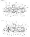
Fig. 1 , a pressure control valve in the related art includes a sleeve having a high-pressure flow path formed on one side thereof to pass high-pressure hydraulic fluid from a hydraulic pump and a hydraulic tank side flow path formed on a circumference thereof to drain the hydraulic fluid in the high-pressure flow path to the hydraulic tank; apoppet 20 controlling a flow rate of the hydraulic fluid flowing from the hydraulic pump side to the hydraulic tank side as sliding in thesleeve 10; apoppet spring 30 elastically supporting thepoppet 20; a pilot poppet 40 draining the high pressure to the hydraulic tank if the high pressure that exceeds a set value is generated in a pressure chamber formed in thesleeve 10; avalve seat 50 installed to face thepoppet 20 so as to form the set pressure in the pressure chamber in thesleeve 10; apilot piston 60 sliding in thepoppet 20 by an initial hydraulic pump pressure to be in contact with thepilot poppet 40; apilot piston spring 70 elastically supporting thepilot piston 60; apilot poppet spring 80 elastically supporting the pilot poppet 40, amain piston 100 slidably coupled to the inside of theguide 90 to variable adjust the set pressure in the pressure chamber in accordance with pilot signal pressure; amain piston spring 110 elastically installed in theguide 90 to elastically support themain piston 100; astopper 120 controlling movement of themain piston 100; acontrol plug 130 controlling the set pressure of themain piston 100; afastening member 141 fastened to theguide 90 to prevent a pressure change after setting the set pressure of a pressure control valve; and a fasteningmember 142 fastened to thecontrol plug 130. - If the hydraulic fluid on the pilot line is pressed through a
connection port 150, the hydraulic fluid is introduced at themain piston 100 through aline 2 formed on theguide 90. Through this, themain piston 100 moves in the right direction in the drawing to press themain piston spring 110 that fixedly supports themain piston 100. At the same time, the pilot poppetspring 80 moves in a direction where the elastic force of the pilot poppetspring 80 is lowered, and thus the pressure set value that is applied to the hydraulic pump is decreased to change the pressure set condition. At this time, the stick phenomenon occurs. That is, even if a desired pressure set value is input, the actual pressure does not coincide with the set pressure. This is because themain piston 100 and thestopper 120 are in close contact with each other to achieve a sealing effect between close contact surfaces thereof, and the hydraulic fluid in themain piston 100 is unable to be smoothly drained, but has a force to push themain piston 100 in the left direction in the drawing. Due to the increased force in the left direction in the drawing, pilot pressure to move themain piston 100 in the right direction in the drawing is increased to be the major cause of the initial pressure abnormality. - When the
main piston 100 moves for the distance "X" in this state, the hydraulic fluid is not smoothly drained through the gap between themain piston 100 and thestopper 120, and a damping phenomenon occurs at a stroke end portion to lower the control pressure. - Therefore, the present invention has been made to solve the above-mentioned problems occurring in the related art, and one embodiment of the present invention is related to a pressure control valve, in which hydraulic fluid in a piston is smoothly drained, and thus control pressure is prevented from being instantaneously dropped to make a set pressure and an actual pressure equal to each other.
- In accordance with an aspect of the present invention, there is provided a pressure control valve, which includes a
sleeve 10 having an inlet port formed thereon to receive hydraulic fluid from a hydraulic pump and a hydraulic tank flow path formed thereon to communicate with a hydraulic tank; apoppet 20 slidably coupled in thesleeve 10 to open/close a flow path between the inlet port and the hydraulic tank flow path; apoppet spring 30 elastically supporting the flow path between the inlet port and the hydraulic tank flow path in a closed state by pressing thepoppet 20; avalve seat 50 installed to face thepoppet 20 so as to form a set pressure in a pressure chamber in thesleeve 10; a pilot poppet 40 draining the hydraulic fluid in the pressure chamber to the hydraulic tank by opening a flow path of thevalve seat 50 when high pressure that exceeds the set pressure is produced in the pressure chamber; apilot poppet spring 80 elastically supporting the flow path of thevalve seat 50 in a closed state by pressing thepilot poppet 40; amain piston 100 coupled to thesleeve 10 to make aguide 90 coupled to aplug 1 that is coupled to thesleeve 10 and to variably adjust the set pressure in the pressure chamber in accordance with pilot signal pressure that is supplied from an outside; astopper 120 having aflow path 121 for preventing damping in a contact portion that faces aninner flow path 101 of themain piston 100 and eliminating a stick phenomenon so that the hydraulic fluid in themain piston 100 is smoothly drained; anadjustment plug 130 coupled to theguide 90 to adjust a set pressure of amain piston spring 110 that supports themain piston 100; and aconnection port 150 rotatably coupled to an outer side surface of theplug 1 to form a path that communicates with the pilot port. - It is preferable that the flow path for preventing the damping and eliminating the stick phenomenon has a cross-section that is in the form of a "V"-shaped groove, and concave grooves are formed at every angle of 90° or 180° in a circumferential direction and in a length direction of the "V"-shaped groove of the cross-section.
- Since the hydraulic fluid in the piston can flow smoothly through the gap between the stopper contact surfaces, the pressure setting time of the relief valve can be reduced and the accurate pressure control becomes possible to achieve production of good-quality products.
- The above objects, other features and advantages of the present invention will become more apparent by describing the preferred embodiments thereof with reference to the accompanying drawings, in which:
-
Fig. 1 is a cross-sectional view of a pressure control valve in the related art; -
Fig. 2 is a cross-sectional view of a pressure control valve according to an embodiment of the present invention; -
Fig. 3 is a graph illustrating pilot pressure versus pressure; -
Fig. 4 is an enlarged cross-sectional view of a main part according to an embodiment of the present invention; -
Fig. 5 is a cross-sectional view explaining a case where a pilot pressure path is closed during an overload operation; and -
Fig. 6 is a cross-sectional view explaining a case where the pilot pressure path is opened when a pressure set value is changed. - Hereinafter, a preferred embodiment of the present invention will be described in detail with reference to the accompanying drawings. The matters defined in the description, such as the detailed construction and elements, are nothing but specific details provided to assist those of ordinary skill in the art in a comprehensive understanding of the invention, and the present invention is not limited to the embodiments disclosed hereinafter.
-
Fig. 2 is a cross-sectional view illustrating the configuration of a pressure control valve according to an embodiment of the present invention.Fig. 3 is a graph illustrating pilot pressure versus pressure.Fig. 4 shows astopper 120 as seen in the drawing. Thestopper 120 serves to control the stroke of amain piston 100 and to make hydraulic fluid in amain piston 100 flow to a drain side through a gap between themain piston 100 and thestopper 120. In this case, as shown inFig. 2 , themain piston 100 and thestopper 120 are not spaced apart from each other for a distance "X", but are in close surface contact with each other to achieve a sealing effect. At this time, hydraulic fluid in themain piston 100 is unable to flow to the drain side, but has a force to push themain piston 100 in the left direction. Due to the increased force in the left direction, pilot pressure to move themain piston 100 in the right direction is increased to be the major cause of initial pressure abnormality. If the hydraulic fluid is not smoothly drained through the gap between themain piston 100 and thestopper 120 while themain piston 100 moves for the distance "X" in this state, a damping phenomenon occurs at a stroke end portion.Fig. 3 is a graph showing an abnormal pressure state (a) where the damping phenomenon occurs and control pressure is instantaneously dropped and a normal pressure state (b) where there is no stick phenomenon. -
Fig. 4 illustrates a left end portion of thestopper 120, as seen in the drawing, in order to prevent such a damping phenomenon. Referring toFig. 4 , a processed cross-sectional surface of a contact portion of thestopper 120 that faces aninner flow path 101 of themain piston 100 is in the form of a "V"-shaped groove to form aflow path 121. In order to drain the hydraulic fluid in themain piston 100 more smoothly, theflow path 121 may have a cross-section that is in the form of a "V"-shaped groove, and concave grooves may be formed at every angle of 90° or 180° in the circumferential direction and in the length direction of the "V"-shaped groove of the cross-section. -
Fig. 5 is a cross-sectional view explaining a case where a pilot pressure path is closed during an overload operation. Referring toFig. 5 , in the case where the pressure of the hydraulic fluid has a normal pressure set value, the hydraulic fluid that is discharged from the hydraulic pump flows into a pressure chamber D through an orifice provided in apoppet 20. In this case, due to a difference in cross-sectional surface between pressure-receiving portions, thepoppet 20 is in close contact with a facing surface of aninner valve seat 50 of asleeve 10. If the pressure of the hydraulic fluid reaches a pressure set value that is determined by apilot poppet spring 80, apilot poppet 40 is opened, and the hydraulic fluid flows from the pressure chamber D to a hydraulic tank through thevalve seat 50 and aline 1. At the same time, the hydraulic fluid on an inlet side of thesleeve 10, of which the pressure is instantaneously dropped when thepilot poppet 40 is opened, moves to the right side as seen in the drawing to flow to the hydraulic tank. The set pressure at that time changes an elastic force of the pilot poppetspring 80 through the adjustment of theguide 90 to exert an influence on the set pressure.Fig. 6 is a cross-sectional view explaining a case where the pilot pressure path is opened when the pressure set value is changed. Referring toFig. 6 , if the hydraulic fluid on the pilot line is pressed and the hydraulic fluid arrives at themain piston 100 through aline 2 formed on theguide 90, themain piston 100 moves to the right side in the drawing. In this case, amain piston spring 110 is compressed and the pilot poppetspring 80 moves in a direction where the elastic force of thepilot poppet spring 80 is lowered, so that the pressure set value that is applied to the hydraulic pump is decreased to change the pressure set condition. Aconnection port 150 is configured to be rotatable at 360 degrees and to be connectable to a pipe port, and a drain port is separately installed in theconnection port 150. The hydraulic fluid that is discharged from the hydraulic pump passes through the orifice in thepoppet 20, and stays in the pressure chamber D through apilot piston 60. At this time, the hydraulic fluid does not flow to the hydraulic tank side by the action of abackup ring 160 and an O-ring 170. If the pilot pressure is adjusted and themain piston 120 move to the right side in the drawing after the initial pressure setting, the set pressure of thepilot poppet spring 80 is decreased.
Claims (2)
- A pressure control valve comprising:a sleeve having an inlet port formed thereon to receive hydraulic fluid from a hydraulic pump and a hydraulic tank flow path formed thereon to communicate with a hydraulic tank;a poppet slidably coupled in the sleeve to open/close a flow path between the inlet port and the hydraulic tank flow path;a poppet spring elastically supporting the flow path between the inlet port and the hydraulic tank flow path in a closed state by pressing the poppet;a valve seat installed to face the poppet so as to form a set pressure in a pressure chamber in the sleeve;a pilot poppet draining the hydraulic fluid in the pressure chamber to the hydraulic tank by opening a flow path of the valve seat when high pressure that exceeds the set pressure is produced in the pressure chamber;a pilot poppet spring elastically supporting the flow path of the valve seat in a closed state by pressing the pilot poppet;a main piston coupled to the sleeve to make a guide coupled to a plug that is coupled to the sleeve and to variably adjust the set pressure in the pressure chamber in accordance with pilot signal pressure that is supplied from an outside;a stopper having a flow path for preventing damping in a contact portion that faces an inner flow path of the main piston and eliminating a stick phenomenon so that the hydraulic fluid in the main piston is smoothly drained;an adjustment plug coupled to the guide to adjust a set pressure of a main piston spring that supports the main piston; anda connection port rotatably coupled to an outer side surface of the plug to form a path that communicates with the pilot port.
- The pressure control valve according to claim 1, wherein the flow path for preventing the damping and eliminating the stick phenomenon has a cross-section that is in the form of a "V"-shaped groove, and concave grooves are formed at every angle of 90° or 180° in a circumferential direction and in a length direction of the "V"-shaped groove of the cross-section.
Applications Claiming Priority (1)
| Application Number | Priority Date | Filing Date | Title |
|---|---|---|---|
| PCT/KR2010/004377 WO2012005390A1 (en) | 2010-07-06 | 2010-07-06 | Valve for controlling pressure |
Publications (3)
| Publication Number | Publication Date |
|---|---|
| EP2592319A1 true EP2592319A1 (en) | 2013-05-15 |
| EP2592319A4 EP2592319A4 (en) | 2017-02-15 |
| EP2592319B1 EP2592319B1 (en) | 2020-12-09 |
Family
ID=45441353
Family Applications (1)
| Application Number | Title | Priority Date | Filing Date |
|---|---|---|---|
| EP10854464.4A Not-in-force EP2592319B1 (en) | 2010-07-06 | 2010-07-06 | Valve for controlling pressure |
Country Status (6)
| Country | Link |
|---|---|
| US (1) | US8733391B2 (en) |
| EP (1) | EP2592319B1 (en) |
| JP (1) | JP5714704B2 (en) |
| KR (1) | KR101689673B1 (en) |
| CN (1) | CN102959298B (en) |
| WO (1) | WO2012005390A1 (en) |
Cited By (2)
| Publication number | Priority date | Publication date | Assignee | Title |
|---|---|---|---|---|
| CN107939767A (en) * | 2017-12-28 | 2018-04-20 | 邵立坤 | A kind of oil supplementation buffer valve |
| CN107939766A (en) * | 2017-12-28 | 2018-04-20 | 邵立坤 | A kind of oil supplementation buffer valve |
Families Citing this family (15)
| Publication number | Priority date | Publication date | Assignee | Title |
|---|---|---|---|---|
| KR101820324B1 (en) | 2011-03-07 | 2018-02-28 | 볼보 컨스트럭션 이큅먼트 에이비 | Hydraulic circuit for pipe layer |
| KR101631956B1 (en) | 2012-05-21 | 2016-06-20 | 볼보 컨스트럭션 이큅먼트 에이비 | Hydraulic system for construction machinery |
| US9611870B2 (en) | 2013-02-05 | 2017-04-04 | Volvo Construction Equipment Ab | Construction equipment pressure control valve |
| WO2014203369A1 (en) * | 2013-06-20 | 2014-12-24 | 株式会社 島津製作所 | Pressure control valve and control valve |
| CN106232907B (en) | 2014-04-29 | 2018-11-02 | 沃尔沃建造设备有限公司 | Flow control valve for engineering machinery |
| KR200486163Y1 (en) | 2016-07-05 | 2018-04-09 | 훌루테크 주식회사 | main control valve assembly for construction machinery |
| US10437269B1 (en) * | 2017-10-06 | 2019-10-08 | Sun Hydraulics, Llc | Electrohydraulic counterbalance and pressure relief valve |
| US10794510B1 (en) | 2017-12-20 | 2020-10-06 | Sun Hydraulics, Llc | Electrohydraulic counterbalance and pressure relief valve |
| US10495117B1 (en) | 2018-04-17 | 2019-12-03 | Sun Hydraulics, Llc | Electrohydraulic counterbalance and pressure relief valve |
| CN108412922B (en) * | 2018-05-07 | 2019-11-15 | 西安航空制动科技有限公司 | Aircraft hydraulic brake system pressure regulator |
| US10775812B1 (en) * | 2019-01-22 | 2020-09-15 | Sun Hydraulics, Llc | Inverse proportional pressure relief valve |
| US10683879B1 (en) | 2019-01-22 | 2020-06-16 | Sun Hydraulics, Llc | Two-port electrohydraulic counterbalance valve |
| CN110259752A (en) * | 2019-07-15 | 2019-09-20 | 宁波克泰液压有限公司 | Threaded insertion pilot depressurizes second level overflow valve |
| JP7643841B2 (en) * | 2020-07-01 | 2025-03-11 | カヤバ株式会社 | Relief Valve |
| JP7795924B2 (en) * | 2022-01-17 | 2026-01-08 | 川崎重工業株式会社 | Relief valve |
Family Cites Families (20)
| Publication number | Priority date | Publication date | Assignee | Title |
|---|---|---|---|---|
| JPS55112463A (en) * | 1979-02-20 | 1980-08-30 | Kayaba Ind Co Ltd | Pressure control valve |
| US4476890A (en) * | 1981-06-12 | 1984-10-16 | Kayaba Kogyo Kabushiki Kaisha | Pressure control valve |
| JPH0791557A (en) * | 1993-09-28 | 1995-04-04 | Komatsu Ltd | Relief valve |
| JPH07248067A (en) * | 1994-03-11 | 1995-09-26 | Kayaba Ind Co Ltd | Relief valve |
| JPH1194105A (en) * | 1997-09-24 | 1999-04-09 | Shin Caterpillar Mitsubishi Ltd | Relief valve and its set pressure adjusting device |
| DE19744337A1 (en) * | 1997-10-07 | 1999-04-08 | Mannesmann Rexroth Ag | Pilot operated pressure relief valve |
| JP2000130619A (en) * | 1998-10-23 | 2000-05-12 | Neriki:Kk | Pressure reducing device |
| US6039070A (en) * | 1998-11-09 | 2000-03-21 | Sun Hydraulics Corp. | Pilot operated pressure valve |
| JP2000265919A (en) * | 1999-03-16 | 2000-09-26 | Bosch Automotive Systems Corp | Solenoid fuel injection valve |
| JP4302302B2 (en) * | 2000-08-24 | 2009-07-22 | カヤバ工業株式会社 | Direct acting relief valve |
| JP2002295329A (en) * | 2001-01-25 | 2002-10-09 | Hitachi Ltd | Electromagnetic fuel injection valve and fuel injection device |
| US6805155B2 (en) * | 2001-11-16 | 2004-10-19 | Hydraforce, Inc. | Cartridge relief valve with improved stability |
| KR100493325B1 (en) * | 2001-12-18 | 2005-06-07 | 볼보 컨스트럭션 이키프먼트 홀딩 스웨덴 에이비 | hydraulic relief valve |
| KR100586023B1 (en) | 2004-02-12 | 2006-06-01 | 볼보 컨스트럭션 이키프먼트 홀딩 스웨덴 에이비 | Relief valve |
| KR100764119B1 (en) * | 2004-02-25 | 2007-10-08 | 볼보 컨스트럭션 이키프먼트 홀딩 스웨덴 에이비 | Pilot Poppet Relief Valve |
| KR100652875B1 (en) * | 2005-09-15 | 2006-12-01 | 볼보 컨스트럭션 이키프먼트 홀딩 스웨덴 에이비 | Hydraulic relief valve |
| KR20080097029A (en) * | 2007-04-30 | 2008-11-04 | 볼보 컨스트럭션 이키프먼트 홀딩 스웨덴 에이비 | 2-stage pressure control valve |
| KR100961431B1 (en) * | 2008-02-25 | 2010-06-09 | 볼보 컨스트럭션 이키프먼트 홀딩 스웨덴 에이비 | Pressure control valve |
| CN201232784Y (en) * | 2008-07-17 | 2009-05-06 | 贵州枫阳液压有限责任公司 | Load holding valve |
| KR100950571B1 (en) * | 2009-02-27 | 2010-04-01 | (주)동우정공 | Relief valve of heavy equipment |
-
2010
- 2010-07-06 WO PCT/KR2010/004377 patent/WO2012005390A1/en not_active Ceased
- 2010-07-06 KR KR1020127033039A patent/KR101689673B1/en not_active Expired - Fee Related
- 2010-07-06 US US13/808,198 patent/US8733391B2/en active Active
- 2010-07-06 CN CN201080067746.4A patent/CN102959298B/en not_active Expired - Fee Related
- 2010-07-06 JP JP2013518205A patent/JP5714704B2/en not_active Expired - Fee Related
- 2010-07-06 EP EP10854464.4A patent/EP2592319B1/en not_active Not-in-force
Non-Patent Citations (1)
| Title |
|---|
| See references of WO2012005390A1 * |
Cited By (2)
| Publication number | Priority date | Publication date | Assignee | Title |
|---|---|---|---|---|
| CN107939767A (en) * | 2017-12-28 | 2018-04-20 | 邵立坤 | A kind of oil supplementation buffer valve |
| CN107939766A (en) * | 2017-12-28 | 2018-04-20 | 邵立坤 | A kind of oil supplementation buffer valve |
Also Published As
| Publication number | Publication date |
|---|---|
| CN102959298A (en) | 2013-03-06 |
| US8733391B2 (en) | 2014-05-27 |
| WO2012005390A1 (en) | 2012-01-12 |
| US20130112291A1 (en) | 2013-05-09 |
| EP2592319A4 (en) | 2017-02-15 |
| JP2013529767A (en) | 2013-07-22 |
| JP5714704B2 (en) | 2015-05-07 |
| CN102959298B (en) | 2015-05-06 |
| KR101689673B1 (en) | 2016-12-26 |
| KR20130095195A (en) | 2013-08-27 |
| EP2592319B1 (en) | 2020-12-09 |
Similar Documents
| Publication | Publication Date | Title |
|---|---|---|
| US8733391B2 (en) | Valve for controlling pressure | |
| KR100961431B1 (en) | Pressure control valve | |
| KR100950571B1 (en) | Relief valve of heavy equipment | |
| EP2312414B1 (en) | Pressure control valve | |
| EP3213165B1 (en) | Flowrate control device for a fluid | |
| CN103038558B (en) | valve configuration | |
| CA2843920C (en) | Fluid valves having multiple fluid flow control members | |
| KR102357069B1 (en) | Bypass and pressure adjustment valve | |
| EP3670912A1 (en) | Pressure regulating bypass valve | |
| US10927862B2 (en) | Double-acting overflow valve of a working cylinder and master cylinder | |
| US10247209B2 (en) | Control device for zero-leak directional control valves | |
| KR102088562B1 (en) | Pilot poppet type relief valve | |
| US6047944A (en) | Poppet with a flow increasing element for limiting movement thereof in a poppet valve | |
| EP1821014B1 (en) | Relief valve | |
| EP2834544A1 (en) | Load holding valve | |
| JP4557283B2 (en) | Fluid pressure relief valve | |
| JP4842716B2 (en) | Pilot check valve and fluid pressure circuit having the same | |
| RU2313715C2 (en) | Safety - makeup modular type hydraulic valve for incorporated mounting and high pressures | |
| US20150198182A1 (en) | Electrohydraulic control valve |
Legal Events
| Date | Code | Title | Description |
|---|---|---|---|
| PUAI | Public reference made under article 153(3) epc to a published international application that has entered the european phase |
Free format text: ORIGINAL CODE: 0009012 |
|
| 17P | Request for examination filed |
Effective date: 20130102 |
|
| AK | Designated contracting states |
Kind code of ref document: A1 Designated state(s): AL AT BE BG CH CY CZ DE DK EE ES FI FR GB GR HR HU IE IS IT LI LT LU LV MC MK MT NL NO PL PT RO SE SI SK SM TR |
|
| DAX | Request for extension of the european patent (deleted) | ||
| RA4 | Supplementary search report drawn up and despatched (corrected) |
Effective date: 20170118 |
|
| RIC1 | Information provided on ipc code assigned before grant |
Ipc: F16K 17/06 20060101ALI20170112BHEP Ipc: F16K 17/10 20060101ALI20170112BHEP Ipc: F16K 31/12 20060101AFI20170112BHEP Ipc: F15B 13/02 20060101ALI20170112BHEP Ipc: F16K 17/04 20060101ALI20170112BHEP |
|
| STAA | Information on the status of an ep patent application or granted ep patent |
Free format text: STATUS: REQUEST FOR EXAMINATION WAS MADE |
|
| R17P | Request for examination filed (corrected) |
Effective date: 20130102 |
|
| GRAP | Despatch of communication of intention to grant a patent |
Free format text: ORIGINAL CODE: EPIDOSNIGR1 |
|
| STAA | Information on the status of an ep patent application or granted ep patent |
Free format text: STATUS: GRANT OF PATENT IS INTENDED |
|
| RIC1 | Information provided on ipc code assigned before grant |
Ipc: F16K 17/04 20060101ALI20200618BHEP Ipc: F16K 17/06 20060101ALI20200618BHEP Ipc: F15B 13/02 20060101ALI20200618BHEP Ipc: F16K 31/12 20060101AFI20200618BHEP Ipc: F16K 17/10 20060101ALI20200618BHEP |
|
| INTG | Intention to grant announced |
Effective date: 20200708 |
|
| GRAS | Grant fee paid |
Free format text: ORIGINAL CODE: EPIDOSNIGR3 |
|
| GRAA | (expected) grant |
Free format text: ORIGINAL CODE: 0009210 |
|
| STAA | Information on the status of an ep patent application or granted ep patent |
Free format text: STATUS: THE PATENT HAS BEEN GRANTED |
|
| AK | Designated contracting states |
Kind code of ref document: B1 Designated state(s): AL AT BE BG CH CY CZ DE DK EE ES FI FR GB GR HR HU IE IS IT LI LT LU LV MC MK MT NL NO PL PT RO SE SI SK SM TR |
|
| REG | Reference to a national code |
Ref country code: GB Ref legal event code: FG4D |
|
| REG | Reference to a national code |
Ref country code: AT Ref legal event code: REF Ref document number: 1343798 Country of ref document: AT Kind code of ref document: T Effective date: 20201215 Ref country code: CH Ref legal event code: EP |
|
| REG | Reference to a national code |
Ref country code: DE Ref legal event code: R096 Ref document number: 602010066138 Country of ref document: DE |
|
| REG | Reference to a national code |
Ref country code: IE Ref legal event code: FG4D |
|
| PG25 | Lapsed in a contracting state [announced via postgrant information from national office to epo] |
Ref country code: GR Free format text: LAPSE BECAUSE OF FAILURE TO SUBMIT A TRANSLATION OF THE DESCRIPTION OR TO PAY THE FEE WITHIN THE PRESCRIBED TIME-LIMIT Effective date: 20210310 Ref country code: NO Free format text: LAPSE BECAUSE OF FAILURE TO SUBMIT A TRANSLATION OF THE DESCRIPTION OR TO PAY THE FEE WITHIN THE PRESCRIBED TIME-LIMIT Effective date: 20210309 Ref country code: FI Free format text: LAPSE BECAUSE OF FAILURE TO SUBMIT A TRANSLATION OF THE DESCRIPTION OR TO PAY THE FEE WITHIN THE PRESCRIBED TIME-LIMIT Effective date: 20201209 |
|
| REG | Reference to a national code |
Ref country code: AT Ref legal event code: MK05 Ref document number: 1343798 Country of ref document: AT Kind code of ref document: T Effective date: 20201209 |
|
| PG25 | Lapsed in a contracting state [announced via postgrant information from national office to epo] |
Ref country code: LV Free format text: LAPSE BECAUSE OF FAILURE TO SUBMIT A TRANSLATION OF THE DESCRIPTION OR TO PAY THE FEE WITHIN THE PRESCRIBED TIME-LIMIT Effective date: 20201209 Ref country code: SE Free format text: LAPSE BECAUSE OF FAILURE TO SUBMIT A TRANSLATION OF THE DESCRIPTION OR TO PAY THE FEE WITHIN THE PRESCRIBED TIME-LIMIT Effective date: 20201209 Ref country code: BG Free format text: LAPSE BECAUSE OF FAILURE TO SUBMIT A TRANSLATION OF THE DESCRIPTION OR TO PAY THE FEE WITHIN THE PRESCRIBED TIME-LIMIT Effective date: 20210309 |
|
| REG | Reference to a national code |
Ref country code: NL Ref legal event code: MP Effective date: 20201209 |
|
| PG25 | Lapsed in a contracting state [announced via postgrant information from national office to epo] |
Ref country code: NL Free format text: LAPSE BECAUSE OF FAILURE TO SUBMIT A TRANSLATION OF THE DESCRIPTION OR TO PAY THE FEE WITHIN THE PRESCRIBED TIME-LIMIT Effective date: 20201209 Ref country code: HR Free format text: LAPSE BECAUSE OF FAILURE TO SUBMIT A TRANSLATION OF THE DESCRIPTION OR TO PAY THE FEE WITHIN THE PRESCRIBED TIME-LIMIT Effective date: 20201209 |
|
| REG | Reference to a national code |
Ref country code: LT Ref legal event code: MG9D |
|
| PG25 | Lapsed in a contracting state [announced via postgrant information from national office to epo] |
Ref country code: LT Free format text: LAPSE BECAUSE OF FAILURE TO SUBMIT A TRANSLATION OF THE DESCRIPTION OR TO PAY THE FEE WITHIN THE PRESCRIBED TIME-LIMIT Effective date: 20201209 Ref country code: SM Free format text: LAPSE BECAUSE OF FAILURE TO SUBMIT A TRANSLATION OF THE DESCRIPTION OR TO PAY THE FEE WITHIN THE PRESCRIBED TIME-LIMIT Effective date: 20201209 Ref country code: SK Free format text: LAPSE BECAUSE OF FAILURE TO SUBMIT A TRANSLATION OF THE DESCRIPTION OR TO PAY THE FEE WITHIN THE PRESCRIBED TIME-LIMIT Effective date: 20201209 Ref country code: RO Free format text: LAPSE BECAUSE OF FAILURE TO SUBMIT A TRANSLATION OF THE DESCRIPTION OR TO PAY THE FEE WITHIN THE PRESCRIBED TIME-LIMIT Effective date: 20201209 Ref country code: PT Free format text: LAPSE BECAUSE OF FAILURE TO SUBMIT A TRANSLATION OF THE DESCRIPTION OR TO PAY THE FEE WITHIN THE PRESCRIBED TIME-LIMIT Effective date: 20210409 Ref country code: CZ Free format text: LAPSE BECAUSE OF FAILURE TO SUBMIT A TRANSLATION OF THE DESCRIPTION OR TO PAY THE FEE WITHIN THE PRESCRIBED TIME-LIMIT Effective date: 20201209 Ref country code: EE Free format text: LAPSE BECAUSE OF FAILURE TO SUBMIT A TRANSLATION OF THE DESCRIPTION OR TO PAY THE FEE WITHIN THE PRESCRIBED TIME-LIMIT Effective date: 20201209 |
|
| PG25 | Lapsed in a contracting state [announced via postgrant information from national office to epo] |
Ref country code: AT Free format text: LAPSE BECAUSE OF FAILURE TO SUBMIT A TRANSLATION OF THE DESCRIPTION OR TO PAY THE FEE WITHIN THE PRESCRIBED TIME-LIMIT Effective date: 20201209 Ref country code: PL Free format text: LAPSE BECAUSE OF FAILURE TO SUBMIT A TRANSLATION OF THE DESCRIPTION OR TO PAY THE FEE WITHIN THE PRESCRIBED TIME-LIMIT Effective date: 20201209 |
|
| REG | Reference to a national code |
Ref country code: DE Ref legal event code: R097 Ref document number: 602010066138 Country of ref document: DE |
|
| PG25 | Lapsed in a contracting state [announced via postgrant information from national office to epo] |
Ref country code: IS Free format text: LAPSE BECAUSE OF FAILURE TO SUBMIT A TRANSLATION OF THE DESCRIPTION OR TO PAY THE FEE WITHIN THE PRESCRIBED TIME-LIMIT Effective date: 20210409 |
|
| PLBE | No opposition filed within time limit |
Free format text: ORIGINAL CODE: 0009261 |
|
| STAA | Information on the status of an ep patent application or granted ep patent |
Free format text: STATUS: NO OPPOSITION FILED WITHIN TIME LIMIT |
|
| PG25 | Lapsed in a contracting state [announced via postgrant information from national office to epo] |
Ref country code: IT Free format text: LAPSE BECAUSE OF FAILURE TO SUBMIT A TRANSLATION OF THE DESCRIPTION OR TO PAY THE FEE WITHIN THE PRESCRIBED TIME-LIMIT Effective date: 20201209 Ref country code: AL Free format text: LAPSE BECAUSE OF FAILURE TO SUBMIT A TRANSLATION OF THE DESCRIPTION OR TO PAY THE FEE WITHIN THE PRESCRIBED TIME-LIMIT Effective date: 20201209 |
|
| 26N | No opposition filed |
Effective date: 20210910 |
|
| PG25 | Lapsed in a contracting state [announced via postgrant information from national office to epo] |
Ref country code: SI Free format text: LAPSE BECAUSE OF FAILURE TO SUBMIT A TRANSLATION OF THE DESCRIPTION OR TO PAY THE FEE WITHIN THE PRESCRIBED TIME-LIMIT Effective date: 20201209 Ref country code: DK Free format text: LAPSE BECAUSE OF FAILURE TO SUBMIT A TRANSLATION OF THE DESCRIPTION OR TO PAY THE FEE WITHIN THE PRESCRIBED TIME-LIMIT Effective date: 20201209 Ref country code: ES Free format text: LAPSE BECAUSE OF FAILURE TO SUBMIT A TRANSLATION OF THE DESCRIPTION OR TO PAY THE FEE WITHIN THE PRESCRIBED TIME-LIMIT Effective date: 20201209 |
|
| REG | Reference to a national code |
Ref country code: CH Ref legal event code: PL |
|
| GBPC | Gb: european patent ceased through non-payment of renewal fee |
Effective date: 20210706 |
|
| PG25 | Lapsed in a contracting state [announced via postgrant information from national office to epo] |
Ref country code: MC Free format text: LAPSE BECAUSE OF FAILURE TO SUBMIT A TRANSLATION OF THE DESCRIPTION OR TO PAY THE FEE WITHIN THE PRESCRIBED TIME-LIMIT Effective date: 20201209 |
|
| REG | Reference to a national code |
Ref country code: BE Ref legal event code: MM Effective date: 20210731 |
|
| PG25 | Lapsed in a contracting state [announced via postgrant information from national office to epo] |
Ref country code: LI Free format text: LAPSE BECAUSE OF NON-PAYMENT OF DUE FEES Effective date: 20210731 Ref country code: GB Free format text: LAPSE BECAUSE OF NON-PAYMENT OF DUE FEES Effective date: 20210706 Ref country code: CH Free format text: LAPSE BECAUSE OF NON-PAYMENT OF DUE FEES Effective date: 20210731 |
|
| PG25 | Lapsed in a contracting state [announced via postgrant information from national office to epo] |
Ref country code: IS Free format text: LAPSE BECAUSE OF FAILURE TO SUBMIT A TRANSLATION OF THE DESCRIPTION OR TO PAY THE FEE WITHIN THE PRESCRIBED TIME-LIMIT Effective date: 20210409 Ref country code: LU Free format text: LAPSE BECAUSE OF NON-PAYMENT OF DUE FEES Effective date: 20210706 |
|
| PG25 | Lapsed in a contracting state [announced via postgrant information from national office to epo] |
Ref country code: IE Free format text: LAPSE BECAUSE OF NON-PAYMENT OF DUE FEES Effective date: 20210706 Ref country code: BE Free format text: LAPSE BECAUSE OF NON-PAYMENT OF DUE FEES Effective date: 20210731 |
|
| PG25 | Lapsed in a contracting state [announced via postgrant information from national office to epo] |
Ref country code: HU Free format text: LAPSE BECAUSE OF FAILURE TO SUBMIT A TRANSLATION OF THE DESCRIPTION OR TO PAY THE FEE WITHIN THE PRESCRIBED TIME-LIMIT; INVALID AB INITIO Effective date: 20100706 Ref country code: CY Free format text: LAPSE BECAUSE OF FAILURE TO SUBMIT A TRANSLATION OF THE DESCRIPTION OR TO PAY THE FEE WITHIN THE PRESCRIBED TIME-LIMIT Effective date: 20201209 |
|
| PGFP | Annual fee paid to national office [announced via postgrant information from national office to epo] |
Ref country code: FR Payment date: 20230725 Year of fee payment: 14 Ref country code: DE Payment date: 20230726 Year of fee payment: 14 |
|
| PG25 | Lapsed in a contracting state [announced via postgrant information from national office to epo] |
Ref country code: MK Free format text: LAPSE BECAUSE OF FAILURE TO SUBMIT A TRANSLATION OF THE DESCRIPTION OR TO PAY THE FEE WITHIN THE PRESCRIBED TIME-LIMIT Effective date: 20201209 |
|
| PG25 | Lapsed in a contracting state [announced via postgrant information from national office to epo] |
Ref country code: TR Free format text: LAPSE BECAUSE OF FAILURE TO SUBMIT A TRANSLATION OF THE DESCRIPTION OR TO PAY THE FEE WITHIN THE PRESCRIBED TIME-LIMIT Effective date: 20201209 |
|
| PG25 | Lapsed in a contracting state [announced via postgrant information from national office to epo] |
Ref country code: MT Free format text: LAPSE BECAUSE OF FAILURE TO SUBMIT A TRANSLATION OF THE DESCRIPTION OR TO PAY THE FEE WITHIN THE PRESCRIBED TIME-LIMIT Effective date: 20201209 |
|
| REG | Reference to a national code |
Ref country code: DE Ref legal event code: R119 Ref document number: 602010066138 Country of ref document: DE |
|
| PG25 | Lapsed in a contracting state [announced via postgrant information from national office to epo] |
Ref country code: DE Free format text: LAPSE BECAUSE OF NON-PAYMENT OF DUE FEES Effective date: 20250201 |
|
| PG25 | Lapsed in a contracting state [announced via postgrant information from national office to epo] |
Ref country code: FR Free format text: LAPSE BECAUSE OF NON-PAYMENT OF DUE FEES Effective date: 20240731 |