EP2592282B1 - System und Verfahren zur Installation einer Befestigungsstange - Google Patents
System und Verfahren zur Installation einer Befestigungsstange Download PDFInfo
- Publication number
- EP2592282B1 EP2592282B1 EP11195405.3A EP11195405A EP2592282B1 EP 2592282 B1 EP2592282 B1 EP 2592282B1 EP 11195405 A EP11195405 A EP 11195405A EP 2592282 B1 EP2592282 B1 EP 2592282B1
- Authority
- EP
- European Patent Office
- Prior art keywords
- rod
- insertion hole
- fastener rod
- fastener
- starter
- Prior art date
- Legal status (The legal status is an assumption and is not a legal conclusion. Google has not performed a legal analysis and makes no representation as to the accuracy of the status listed.)
- Not-in-force
Links
Images

Classifications
-
- F—MECHANICAL ENGINEERING; LIGHTING; HEATING; WEAPONS; BLASTING
- F16—ENGINEERING ELEMENTS AND UNITS; GENERAL MEASURES FOR PRODUCING AND MAINTAINING EFFECTIVE FUNCTIONING OF MACHINES OR INSTALLATIONS; THERMAL INSULATION IN GENERAL
- F16B—DEVICES FOR FASTENING OR SECURING CONSTRUCTIONAL ELEMENTS OR MACHINE PARTS TOGETHER, e.g. NAILS, BOLTS, CIRCLIPS, CLAMPS, CLIPS OR WEDGES; JOINTS OR JOINTING
- F16B4/00—Shrinkage connections, e.g. assembled with the parts at different temperature; Force fits; Non-releasable friction-grip fastenings
- F16B4/004—Press fits, force fits, interference fits, i.e. fits without heat or chemical treatment
-
- Y—GENERAL TAGGING OF NEW TECHNOLOGICAL DEVELOPMENTS; GENERAL TAGGING OF CROSS-SECTIONAL TECHNOLOGIES SPANNING OVER SEVERAL SECTIONS OF THE IPC; TECHNICAL SUBJECTS COVERED BY FORMER USPC CROSS-REFERENCE ART COLLECTIONS [XRACs] AND DIGESTS
- Y10—TECHNICAL SUBJECTS COVERED BY FORMER USPC
- Y10T—TECHNICAL SUBJECTS COVERED BY FORMER US CLASSIFICATION
- Y10T29/00—Metal working
- Y10T29/49—Method of mechanical manufacture
- Y10T29/49826—Assembling or joining
- Y10T29/49947—Assembling or joining by applying separate fastener
- Y10T29/49963—Threaded fastener
Definitions
- This disclosure relates in general to the field of fasteners, and more particularly to a system and method for installing a fastener rod installation.
- Fastener rods such as dowel pins and threaded studs, can be machined to tight tolerances and are frequently used as fasteners for mechanical components that require such tolerances, such as gear casings, engines, and transmissions in rotorcraft drive systems.
- a liquid primer or oil is often desirable to facilitate a satisfactory fit or reduce corrosion at the interface of the mating components, but the liquid may be highly incompressible and can result in cracked cases due to pressurization or inaccurate install torque when compressed. Systems and methods for remedying this problem can be costly and can result in many scrapped parts.
- EP0743136 (Nippon Pneumatic Manufacturing Co. Ltd.), which describes a method of manufacturing a chisel for impact tool
- US 3970158 Black et al ) which discusses tooth loading for earth boring bits.
- fastener refers generally to a broad class of devices that mechanically join or locate two components together
- fastener rod refers generally to a subset of solid, cylindrical fasteners.
- Fastener rods may include threaded rods (e.g., a stud) and unthreaded rods (e.g., a dowel, dowel rod, dowel pin, etc.).
- threaded rods e.g., a stud
- unthreaded rods e.g., a dowel, dowel rod, dowel pin, etc.
- an interference fit also known as a press fit or friction fit
- friction fit can be achieved by friction after components are mated, rather than by other means of fastening.
- the friction that holds the components together can be greatly increased by compression of one component against the other, which relies on the tensile and compressive strengths and stiffness of the materials the components are made from.
- a transition fit may also bind two components together, but is not so tight that it prevents disassembly.
- a binding fit between a fastener rod and a component can generally be achieved by shaping them so that one or the other (or both) slightly deviate in size from a nominal dimension.
- an unthreaded rod such as a dowel rod may be machined slightly larger than the nominal dimension for an interference fit.
- an insertion hole in a component may be reamed so that it is slightly less than the nominal dimension. If the dowel rod is then pressed into the hole, the dowel rod interferes with the component's occupation of space. The desired result is that they elastically deform slightly, and the interface between them is one of extremely high friction so that even large amounts of torque cannot turn one of them relative to the other.
- An interference fit may also be used for a threaded rod, such as a stud, with overlapping external and internal threads.
- a threaded rod such as a stud
- an interference fit stud can be used if the stud needs to be restrained in its tapped hole against loosening in service or when a nut is removed.
- a primer is often desirable to facilitate an interference fit and/or reduce corrosion in the interface, but the primer may be a highly incompressible fluid and can result in cracked cases or inaccurate install torque when compressed.
- lubricant in a 0.8cm (5/16") stud boss can create pressure in excess of 207MPa (30 ksi) after stud installation. Systems and methods for remedying this problem can be costly and can result in many scrapped parts.
- a drilled vent hole in a housing can allow fluid (i.e., liquid and/or gas) to escape upon installation, but requires additional machining operations that increases component cost and can result in significant waste.
- a drilled fastener rod can also allow fluid to escape upon rod installation, but may only be practical for short rods not exposed to the atmosphere where there is a risk of corrosion on the rod interior. Moreover, the cost for such non-standard parts also increases component cost.
- a keyway or slotted vent may also be cut in the side of a rod, but such a feature can weaken the rod and increase the potential for corrosion. Leaving a sufficient air gap at the bottom of an insertion hole can also reduce pressure, but liquid primer can also build up in the hole if not sufficiently cleaned prior to installation, which can be very susceptible to human error.
- a rod starter insert can substantially reduce or eliminate many of these shortcomings (and others) without modifying parts or significantly increasing cost.
- the rod starter insert is a closed-cell foam having a low density and high compressibility, which can be placed in an insertion hole prior to installation of a fastener rod.
- the insert can displace fluid (e.g., primer and/or oil) in the hole, but may be significantly compressed during installation such that the fastener rod can be fully installed without over-pressurizing the hole.
- Figure 1A is a simplified block diagram of one embodiment of a system for installing a fastener rod into an insertion hole.
- the fastener rod is a stud (i.e., a threaded rod) 10 and the insertion hole is a stud boss 12.
- Stud 10 and stud boss 12 may be lubricated with a fluid, such as primer and oil 14.
- a rod starter 16 may be placed over and longitudinally aligned with stud boss 12.
- Figure 1B is a simplified block diagram of the system of Figure 1A in which rod starter 16 is inserted into stud boss 12 to displace primer and oil 14 from stud boss 12.
- Figure 1C is a simplified block diagram of the system in Figure 1A in which stud 10 is installed into stud boss 12.
- rod starter 16 Installation of stud 10 into stud boss 12 compresses rod starter 16.
- the volume reduction of rod starter 16 may vary considerably based on design requirements, but assuming a 90% reduction in volume, the air pressure in stud boss 12 should only increase by approximately 965kPa (140 psi).
- stud boss 12 provides sufficient room to accommodate residual fluid, compressed air, and rod starter 16.
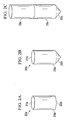
- Figures 2A-2C are simplified schematic diagrams that illustrate additional details that may be associated with certain example embodiments of a rod starter.
- a rod starter may be molded, fabricated, or cut to conform to the shape of any insertion hole, but is preferably a cylindrical block element.
- a rod starter 20a has two opposing ends 21a-22a and an elongated body with a cylindrical wall 23a.
- Rod starter 20a can be installed in a corresponding insertion hole without regard to orientation of ends 21a-22a.
- Figure 2B illustrates a rod starter 20b having a flat end 21b and a distal end 22b adapted to conform to a feature in an insertion hole.
- distal end 22b may be substantially conical to conform to a drill point in an insertion hole, for example.
- rod starter 20b may displace more fluid than rod starter 20a when tapered end 22b is properly oriented and installed in the bottom of a corresponding insertion hole.
- Figure 2C illustrates yet another embodiment of a rod starter 20c bonded to a fastener rod 23c.
- rod starter 20c has a tapered end 22c similar to tapered end 22b, but may alternatively have a flat surface similar to surface 22a.
- a rod starter may also be sized such that fluid can escape an insertion hole through channels or grooves in the side of the starter rod, or between clearance space between the body of the starter and walls of an insertion hole.
- a rod starter element may be constructed from any closed cell foam having sufficiently low density and high compressibility that it can displace fluid in an insertion hole and be compressed to allow full installation of a fastener rod without over-pressurizing the hole.
- a rod starter element may be constructed from rigid polystyrene foam, including expanded or extruded polystyrene foam (e.g., STYROFOAM).
- a rod starter as described herein may be a passive device not requiring changes to components or fastener rods. It can be made of highly compressible and rigid closed cell material that can retain its shape to displace fluid yet may be readily compressed during rod installation. Moreover, a rod starter can be sized such that after insertion, fluid in the hole can be compressed to the maximum amount required by a given design with pressurization of the hole well below design limits.
- a rod starter may be shaped like a cylinder that can be installed in any direction, or like a pointed cylinder that can be installed one way and displace more fluid. A rod starter can also be installed freely prior to rod installation or may be bonded to the rod to further facilitate proper installation.
Landscapes
- Engineering & Computer Science (AREA)
- General Engineering & Computer Science (AREA)
- Mechanical Engineering (AREA)
- Connection Of Plates (AREA)
- Insertion Pins And Rivets (AREA)
- Shafts, Cranks, Connecting Bars, And Related Bearings (AREA)
Claims (12)
- Eine Befestigungsstangen-Starter (16, 20a, 20b, 20c) -Vorrichtung, umfassend:ein erstes Ende (21a, 21b) zum Einklinken einer Befestigungsstange (10, 23c);ein zweites Ende (22a, 22b, 22c) zum Einführen in ein Einführloch (12); undeinen länglichen Körper aus geschlossenzelligem Schaumstoff mit ausreichend geringer Dichte und hoher Komprimierbarkeit, um Flüssigkeit (14) im Einführloch zu verdrängen und um komprimiert zu werden, sodass die Installation der Befestigungsstange in das Einführloch ermöglicht wird.
- Die Vorrichtung von Anspruch 1, wobei der längliche Körper ein überwiegend zylindrischer Körper ist.
- Die Vorrichtung von Anspruch 1 oder Anspruch 2, wobei der geschlossenzellige Schaumstoff ein geschlossenzelliger Polystyrolschaum oder geschlossenzelliger extrudierter Polystyrolschaum ist.
- Die Vorrichtung von Anspruch 1 oder 2 oder 3, wobei das zweite Ende (22a, 22b, 22c) angepasst ist, um sich mit einem Bestandteil des Einführlochs zu verbinden.
- Die Vorrichtung von Anspruch 1 bis 4, wobei das zweite Ende (22a, 22b, 22c) konisch ist.
- Die Vorrichtung von einem vorhergehenden Anspruch, wobei die Befestigungsstange (23c) mit dem ersten Ende verbunden ist.
- Die Vorrichtung von einem vorhergehenden Anspruch, wobei die Befestigungsstange mit einem Gewinde versehen ist.
- Die Vorrichtung von einem vorhergehenden Anspruch, wobei die mit einem Gewinde versehene Befestigungsstange mit dem ersten Ende verbunden ist.
- Die Vorrichtung von einem vorhergehenden Anspruch, wobei der längliche Körper Kanäle zwischen dem ersten Ende und dem zweiten Ende umfasst.
- Die Vorrichtung von einem vorhergehenden Anspruch, wobei der längliche Körper eine entsprechende Größe aufweist, um einen Abstand zwischen dem länglichen Körper und dem Einführloch bereitzustellen.
- Die Vorrichtung von einem vorhergehenden Anspruch, wobei:der längliche Körper im Wesentlichen ein zylindrischer Körper ist;der geschlossenzellige Schaumstoff ein geschlossenzelliger extrudierter Polystyrolschaum ist;die Befestigungsstange mit dem ersten Ende verbunden ist; unddas zweite Ende konisch ist.
- Ein Verfahren zur Installierung einer Befestigungsstange (10, 23c), umfassend:Schmieren eines Einführlochs (12) mit einer Flüssigkeit (14);Einführen eines Starterelements in das Einführloch, wobei das Starterelement einen geschlossenzelligen Schaumstoff umfasst, der eine ausreichend geringe Dichte und hohe Komprimierbarkeit aufweist, um die Flüssigkeit (14) im Einführloch zu verdrängen und um die Installation der Befestigungsstange in das Einführloch zu ermöglichen; undEinführen der Befestigungsstange in das Einführloch auf das Starterelement, wodurch die Flüssigkeit im Einführloch verdrängt und das Starterelement komprimiert wird.
Applications Claiming Priority (1)
| Application Number | Priority Date | Filing Date | Title |
|---|---|---|---|
| US13/294,686 US20130117997A1 (en) | 2011-11-11 | 2011-11-11 | System and Method for Installing a Fastener Rod |
Publications (2)
| Publication Number | Publication Date |
|---|---|
| EP2592282A1 EP2592282A1 (de) | 2013-05-15 |
| EP2592282B1 true EP2592282B1 (de) | 2014-02-12 |
Family
ID=45400987
Family Applications (1)
| Application Number | Title | Priority Date | Filing Date |
|---|---|---|---|
| EP11195405.3A Not-in-force EP2592282B1 (de) | 2011-11-11 | 2011-12-22 | System und Verfahren zur Installation einer Befestigungsstange |
Country Status (3)
| Country | Link |
|---|---|
| US (1) | US20130117997A1 (de) |
| EP (1) | EP2592282B1 (de) |
| CA (1) | CA2788277C (de) |
Families Citing this family (2)
| Publication number | Priority date | Publication date | Assignee | Title |
|---|---|---|---|---|
| US10400812B2 (en) | 2016-09-23 | 2019-09-03 | Bell Helicopter Textron Inc. | Method for fastening |
| CN116060917B (zh) * | 2023-03-23 | 2023-06-06 | 河南方亿密封科技有限公司 | 一种汽车线束护套与密封圈装配组件 |
Family Cites Families (9)
| Publication number | Priority date | Publication date | Assignee | Title |
|---|---|---|---|---|
| US2795818A (en) * | 1954-05-04 | 1957-06-18 | Bertorello Jack | Machine for applying sealing compound to can or container tops |
| US3970158A (en) * | 1975-04-28 | 1976-07-20 | Hughes Tool Company | Tooth loading for earth boring bits |
| US4648414A (en) * | 1984-08-16 | 1987-03-10 | Cel Co., Inc. | Bendable lightweight article for personal grooming and method of making |
| AT397290B (de) * | 1991-06-27 | 1994-03-25 | Semperit Ag | Dübel für spannbetonschwellen |
| JP2834992B2 (ja) * | 1993-11-25 | 1998-12-14 | 日本ニューマチック工業株式会社 | 衝撃動工具用チゼルおよびその製造方法 |
| US6871681B2 (en) * | 2002-11-22 | 2005-03-29 | Miller Dowel Company | Dowel connection system and method |
| US7434635B2 (en) * | 2006-08-11 | 2008-10-14 | Sandvik Intellectual Property Ab | Tin seat for rock drill insert |
| US8365459B2 (en) * | 2007-02-15 | 2013-02-05 | Gary Bennis | Stem guide and replaceable cartridges |
| FR2929299A1 (fr) * | 2008-04-01 | 2009-10-02 | Vape Rail Internat Sa | Gaine permettant la mise en place d'un organe de fixation dans une paroi, notamment la mise en place d'un tire-fond de fixation d'un rail ferroviaire dans une traverse de voie ferree |
-
2011
- 2011-11-11 US US13/294,686 patent/US20130117997A1/en not_active Abandoned
- 2011-12-22 EP EP11195405.3A patent/EP2592282B1/de not_active Not-in-force
-
2012
- 2012-08-30 CA CA2788277A patent/CA2788277C/en active Active
Also Published As
| Publication number | Publication date |
|---|---|
| US20130117997A1 (en) | 2013-05-16 |
| CA2788277C (en) | 2015-11-24 |
| CA2788277A1 (en) | 2013-05-11 |
| EP2592282A1 (de) | 2013-05-15 |
Similar Documents
| Publication | Publication Date | Title |
|---|---|---|
| US4346920A (en) | Threaded connection using variable lead threads | |
| US8777537B2 (en) | Fastener with shear bushing | |
| EP2440814B1 (de) | Dichtungsanordnung | |
| WO2007106801A2 (en) | Nut plate fastener repair assembly | |
| CA2788277C (en) | System and method for installing a fastener rod | |
| CN107178548B (zh) | 单边紧固件组件及其安装方法和系统 | |
| US20160290068A1 (en) | Centralizer for use with wellbore drill collar | |
| EP3126704B1 (de) | Radiale schwingungsdämpfer für drehwellen | |
| JP4926170B2 (ja) | 誤差補償コネクタ | |
| US6742377B2 (en) | Passive-adaptive indentor for stress wave cold working | |
| US7635224B2 (en) | Method of adjusting backlash in a down hole bearing assembly | |
| US20170101841A1 (en) | Blowout Preventer with Ram Packer Assemblies with Support Member | |
| GB2111140A (en) | Seals | |
| CN118251826A (zh) | 用于将解耦元件安装在电机的定子中的通孔中的方法、用于电机的定子以及包括这种类型的定子的电机 | |
| JP2007309513A (ja) | 固定構造および固定方法 | |
| CN116592036A (zh) | 盲结构套筒和相对于第二结构夹持第一结构的系统和方法 | |
| WO2020149819A1 (en) | Systems and methods for coupling a cylinder head to a cylinder block | |
| EP4299923B1 (de) | Verteiler mit reparierbaren gewindeeinsatzanordnungen in verteilerbohrungen | |
| CN107401532B (zh) | 将用于流体动力线性致动器的气缸安装到流道的适配器 | |
| US7455010B2 (en) | Expanded barrel hydraulic cylinder assembly | |
| CN203091808U (zh) | 直孔端面钻模装置 | |
| Smith et al. | New blind, doweling, temporary fastener design and testing | |
| Tian | Selection and Comparative Study of Mechanical Fitting Processes: With a Focus on the Application of Motor Rotor Shaft and Rotor Stack Fitting | |
| CN213235893U (zh) | 一种双向机械摩擦式阻尼器 | |
| MX2009000805A (es) | Porcion de piston para ensamble de piston y un ensamble de piston. |
Legal Events
| Date | Code | Title | Description |
|---|---|---|---|
| PUAI | Public reference made under article 153(3) epc to a published international application that has entered the european phase |
Free format text: ORIGINAL CODE: 0009012 |
|
| 17P | Request for examination filed |
Effective date: 20111222 |
|
| AK | Designated contracting states |
Kind code of ref document: A1 Designated state(s): AL AT BE BG CH CY CZ DE DK EE ES FI FR GB GR HR HU IE IS IT LI LT LU LV MC MK MT NL NO PL PT RO RS SE SI SK SM TR |
|
| AX | Request for extension of the european patent |
Extension state: BA ME |
|
| GRAP | Despatch of communication of intention to grant a patent |
Free format text: ORIGINAL CODE: EPIDOSNIGR1 |
|
| RIC1 | Information provided on ipc code assigned before grant |
Ipc: F16B 4/00 20060101AFI20130910BHEP |
|
| INTG | Intention to grant announced |
Effective date: 20131009 |
|
| GRAS | Grant fee paid |
Free format text: ORIGINAL CODE: EPIDOSNIGR3 |
|
| GRAA | (expected) grant |
Free format text: ORIGINAL CODE: 0009210 |
|
| AK | Designated contracting states |
Kind code of ref document: B1 Designated state(s): AL AT BE BG CH CY CZ DE DK EE ES FI FR GB GR HR HU IE IS IT LI LT LU LV MC MK MT NL NO PL PT RO RS SE SI SK SM TR |
|
| REG | Reference to a national code |
Ref country code: GB Ref legal event code: FG4D |
|
| REG | Reference to a national code |
Ref country code: CH Ref legal event code: EP |
|
| REG | Reference to a national code |
Ref country code: AT Ref legal event code: REF Ref document number: 652284 Country of ref document: AT Kind code of ref document: T Effective date: 20140215 |
|
| REG | Reference to a national code |
Ref country code: IE Ref legal event code: FG4D |
|
| REG | Reference to a national code |
Ref country code: DE Ref legal event code: R096 Ref document number: 602011004928 Country of ref document: DE Effective date: 20140327 |
|
| REG | Reference to a national code |
Ref country code: NL Ref legal event code: VDEP Effective date: 20140212 |
|
| REG | Reference to a national code |
Ref country code: AT Ref legal event code: MK05 Ref document number: 652284 Country of ref document: AT Kind code of ref document: T Effective date: 20140212 |
|
| REG | Reference to a national code |
Ref country code: LT Ref legal event code: MG4D |
|
| PG25 | Lapsed in a contracting state [announced via postgrant information from national office to epo] |
Ref country code: LT Free format text: LAPSE BECAUSE OF FAILURE TO SUBMIT A TRANSLATION OF THE DESCRIPTION OR TO PAY THE FEE WITHIN THE PRESCRIBED TIME-LIMIT Effective date: 20140212 Ref country code: NO Free format text: LAPSE BECAUSE OF FAILURE TO SUBMIT A TRANSLATION OF THE DESCRIPTION OR TO PAY THE FEE WITHIN THE PRESCRIBED TIME-LIMIT Effective date: 20140512 Ref country code: IS Free format text: LAPSE BECAUSE OF FAILURE TO SUBMIT A TRANSLATION OF THE DESCRIPTION OR TO PAY THE FEE WITHIN THE PRESCRIBED TIME-LIMIT Effective date: 20140612 |
|
| PG25 | Lapsed in a contracting state [announced via postgrant information from national office to epo] |
Ref country code: FI Free format text: LAPSE BECAUSE OF FAILURE TO SUBMIT A TRANSLATION OF THE DESCRIPTION OR TO PAY THE FEE WITHIN THE PRESCRIBED TIME-LIMIT Effective date: 20140212 Ref country code: PT Free format text: LAPSE BECAUSE OF FAILURE TO SUBMIT A TRANSLATION OF THE DESCRIPTION OR TO PAY THE FEE WITHIN THE PRESCRIBED TIME-LIMIT Effective date: 20140612 Ref country code: CY Free format text: LAPSE BECAUSE OF FAILURE TO SUBMIT A TRANSLATION OF THE DESCRIPTION OR TO PAY THE FEE WITHIN THE PRESCRIBED TIME-LIMIT Effective date: 20140212 Ref country code: AT Free format text: LAPSE BECAUSE OF FAILURE TO SUBMIT A TRANSLATION OF THE DESCRIPTION OR TO PAY THE FEE WITHIN THE PRESCRIBED TIME-LIMIT Effective date: 20140212 Ref country code: NL Free format text: LAPSE BECAUSE OF FAILURE TO SUBMIT A TRANSLATION OF THE DESCRIPTION OR TO PAY THE FEE WITHIN THE PRESCRIBED TIME-LIMIT Effective date: 20140212 Ref country code: ES Free format text: LAPSE BECAUSE OF FAILURE TO SUBMIT A TRANSLATION OF THE DESCRIPTION OR TO PAY THE FEE WITHIN THE PRESCRIBED TIME-LIMIT Effective date: 20140212 Ref country code: SE Free format text: LAPSE BECAUSE OF FAILURE TO SUBMIT A TRANSLATION OF THE DESCRIPTION OR TO PAY THE FEE WITHIN THE PRESCRIBED TIME-LIMIT Effective date: 20140212 |
|
| PG25 | Lapsed in a contracting state [announced via postgrant information from national office to epo] |
Ref country code: BE Free format text: LAPSE BECAUSE OF FAILURE TO SUBMIT A TRANSLATION OF THE DESCRIPTION OR TO PAY THE FEE WITHIN THE PRESCRIBED TIME-LIMIT Effective date: 20140212 Ref country code: LV Free format text: LAPSE BECAUSE OF FAILURE TO SUBMIT A TRANSLATION OF THE DESCRIPTION OR TO PAY THE FEE WITHIN THE PRESCRIBED TIME-LIMIT Effective date: 20140212 Ref country code: RS Free format text: LAPSE BECAUSE OF FAILURE TO SUBMIT A TRANSLATION OF THE DESCRIPTION OR TO PAY THE FEE WITHIN THE PRESCRIBED TIME-LIMIT Effective date: 20140212 Ref country code: HR Free format text: LAPSE BECAUSE OF FAILURE TO SUBMIT A TRANSLATION OF THE DESCRIPTION OR TO PAY THE FEE WITHIN THE PRESCRIBED TIME-LIMIT Effective date: 20140212 |
|
| PG25 | Lapsed in a contracting state [announced via postgrant information from national office to epo] |
Ref country code: RO Free format text: LAPSE BECAUSE OF FAILURE TO SUBMIT A TRANSLATION OF THE DESCRIPTION OR TO PAY THE FEE WITHIN THE PRESCRIBED TIME-LIMIT Effective date: 20140212 Ref country code: EE Free format text: LAPSE BECAUSE OF FAILURE TO SUBMIT A TRANSLATION OF THE DESCRIPTION OR TO PAY THE FEE WITHIN THE PRESCRIBED TIME-LIMIT Effective date: 20140212 Ref country code: CZ Free format text: LAPSE BECAUSE OF FAILURE TO SUBMIT A TRANSLATION OF THE DESCRIPTION OR TO PAY THE FEE WITHIN THE PRESCRIBED TIME-LIMIT Effective date: 20140212 Ref country code: DK Free format text: LAPSE BECAUSE OF FAILURE TO SUBMIT A TRANSLATION OF THE DESCRIPTION OR TO PAY THE FEE WITHIN THE PRESCRIBED TIME-LIMIT Effective date: 20140212 |
|
| REG | Reference to a national code |
Ref country code: DE Ref legal event code: R097 Ref document number: 602011004928 Country of ref document: DE |
|
| PG25 | Lapsed in a contracting state [announced via postgrant information from national office to epo] |
Ref country code: SK Free format text: LAPSE BECAUSE OF FAILURE TO SUBMIT A TRANSLATION OF THE DESCRIPTION OR TO PAY THE FEE WITHIN THE PRESCRIBED TIME-LIMIT Effective date: 20140212 Ref country code: PL Free format text: LAPSE BECAUSE OF FAILURE TO SUBMIT A TRANSLATION OF THE DESCRIPTION OR TO PAY THE FEE WITHIN THE PRESCRIBED TIME-LIMIT Effective date: 20140212 |
|
| PLBE | No opposition filed within time limit |
Free format text: ORIGINAL CODE: 0009261 |
|
| STAA | Information on the status of an ep patent application or granted ep patent |
Free format text: STATUS: NO OPPOSITION FILED WITHIN TIME LIMIT |
|
| 26N | No opposition filed |
Effective date: 20141113 |
|
| REG | Reference to a national code |
Ref country code: DE Ref legal event code: R097 Ref document number: 602011004928 Country of ref document: DE Effective date: 20141113 |
|
| PG25 | Lapsed in a contracting state [announced via postgrant information from national office to epo] |
Ref country code: SI Free format text: LAPSE BECAUSE OF FAILURE TO SUBMIT A TRANSLATION OF THE DESCRIPTION OR TO PAY THE FEE WITHIN THE PRESCRIBED TIME-LIMIT Effective date: 20140212 |
|
| PG25 | Lapsed in a contracting state [announced via postgrant information from national office to epo] |
Ref country code: LU Free format text: LAPSE BECAUSE OF FAILURE TO SUBMIT A TRANSLATION OF THE DESCRIPTION OR TO PAY THE FEE WITHIN THE PRESCRIBED TIME-LIMIT Effective date: 20141222 |
|
| REG | Reference to a national code |
Ref country code: CH Ref legal event code: PL |
|
| REG | Reference to a national code |
Ref country code: IE Ref legal event code: MM4A |
|
| PG25 | Lapsed in a contracting state [announced via postgrant information from national office to epo] |
Ref country code: IE Free format text: LAPSE BECAUSE OF NON-PAYMENT OF DUE FEES Effective date: 20141222 Ref country code: LI Free format text: LAPSE BECAUSE OF NON-PAYMENT OF DUE FEES Effective date: 20141231 Ref country code: CH Free format text: LAPSE BECAUSE OF NON-PAYMENT OF DUE FEES Effective date: 20141231 |
|
| REG | Reference to a national code |
Ref country code: FR Ref legal event code: PLFP Year of fee payment: 5 |
|
| PG25 | Lapsed in a contracting state [announced via postgrant information from national office to epo] |
Ref country code: SM Free format text: LAPSE BECAUSE OF FAILURE TO SUBMIT A TRANSLATION OF THE DESCRIPTION OR TO PAY THE FEE WITHIN THE PRESCRIBED TIME-LIMIT Effective date: 20140212 |
|
| PG25 | Lapsed in a contracting state [announced via postgrant information from national office to epo] |
Ref country code: MC Free format text: LAPSE BECAUSE OF FAILURE TO SUBMIT A TRANSLATION OF THE DESCRIPTION OR TO PAY THE FEE WITHIN THE PRESCRIBED TIME-LIMIT Effective date: 20140212 |
|
| PG25 | Lapsed in a contracting state [announced via postgrant information from national office to epo] |
Ref country code: GR Free format text: LAPSE BECAUSE OF FAILURE TO SUBMIT A TRANSLATION OF THE DESCRIPTION OR TO PAY THE FEE WITHIN THE PRESCRIBED TIME-LIMIT Effective date: 20140513 Ref country code: BG Free format text: LAPSE BECAUSE OF FAILURE TO SUBMIT A TRANSLATION OF THE DESCRIPTION OR TO PAY THE FEE WITHIN THE PRESCRIBED TIME-LIMIT Effective date: 20140212 |
|
| PG25 | Lapsed in a contracting state [announced via postgrant information from national office to epo] |
Ref country code: TR Free format text: LAPSE BECAUSE OF FAILURE TO SUBMIT A TRANSLATION OF THE DESCRIPTION OR TO PAY THE FEE WITHIN THE PRESCRIBED TIME-LIMIT Effective date: 20140212 Ref country code: MT Free format text: LAPSE BECAUSE OF FAILURE TO SUBMIT A TRANSLATION OF THE DESCRIPTION OR TO PAY THE FEE WITHIN THE PRESCRIBED TIME-LIMIT Effective date: 20140212 Ref country code: HU Free format text: LAPSE BECAUSE OF FAILURE TO SUBMIT A TRANSLATION OF THE DESCRIPTION OR TO PAY THE FEE WITHIN THE PRESCRIBED TIME-LIMIT; INVALID AB INITIO Effective date: 20111222 |
|
| REG | Reference to a national code |
Ref country code: FR Ref legal event code: PLFP Year of fee payment: 6 |
|
| PG25 | Lapsed in a contracting state [announced via postgrant information from national office to epo] |
Ref country code: IT Free format text: LAPSE BECAUSE OF NON-PAYMENT OF DUE FEES Effective date: 20151222 |
|
| PG25 | Lapsed in a contracting state [announced via postgrant information from national office to epo] |
Ref country code: IT Free format text: LAPSE BECAUSE OF NON-PAYMENT OF DUE FEES Effective date: 20151222 |
|
| PGRI | Patent reinstated in contracting state [announced from national office to epo] |
Ref country code: IT Effective date: 20170710 |
|
| REG | Reference to a national code |
Ref country code: FR Ref legal event code: PLFP Year of fee payment: 7 |
|
| PG25 | Lapsed in a contracting state [announced via postgrant information from national office to epo] |
Ref country code: MK Free format text: LAPSE BECAUSE OF FAILURE TO SUBMIT A TRANSLATION OF THE DESCRIPTION OR TO PAY THE FEE WITHIN THE PRESCRIBED TIME-LIMIT Effective date: 20140212 |
|
| PG25 | Lapsed in a contracting state [announced via postgrant information from national office to epo] |
Ref country code: AL Free format text: LAPSE BECAUSE OF FAILURE TO SUBMIT A TRANSLATION OF THE DESCRIPTION OR TO PAY THE FEE WITHIN THE PRESCRIBED TIME-LIMIT Effective date: 20140212 |
|
| PGFP | Annual fee paid to national office [announced via postgrant information from national office to epo] |
Ref country code: DE Payment date: 20211227 Year of fee payment: 11 Ref country code: GB Payment date: 20211227 Year of fee payment: 11 Ref country code: FR Payment date: 20211227 Year of fee payment: 11 |
|
| PGFP | Annual fee paid to national office [announced via postgrant information from national office to epo] |
Ref country code: IT Payment date: 20211221 Year of fee payment: 11 |
|
| REG | Reference to a national code |
Ref country code: DE Ref legal event code: R119 Ref document number: 602011004928 Country of ref document: DE |
|
| P01 | Opt-out of the competence of the unified patent court (upc) registered |
Effective date: 20230602 |
|
| GBPC | Gb: european patent ceased through non-payment of renewal fee |
Effective date: 20221222 |
|
| PG25 | Lapsed in a contracting state [announced via postgrant information from national office to epo] |
Ref country code: GB Free format text: LAPSE BECAUSE OF NON-PAYMENT OF DUE FEES Effective date: 20221222 Ref country code: DE Free format text: LAPSE BECAUSE OF NON-PAYMENT OF DUE FEES Effective date: 20230701 |
|
| PG25 | Lapsed in a contracting state [announced via postgrant information from national office to epo] |
Ref country code: FR Free format text: LAPSE BECAUSE OF NON-PAYMENT OF DUE FEES Effective date: 20221231 |
|
| PG25 | Lapsed in a contracting state [announced via postgrant information from national office to epo] |
Ref country code: IT Free format text: LAPSE BECAUSE OF NON-PAYMENT OF DUE FEES Effective date: 20221222 |